EP3802927B1 - Ringspinnanlage und verfahren zu ihrem betrieb - Google Patents
Ringspinnanlage und verfahren zu ihrem betrieb Download PDFInfo
- Publication number
- EP3802927B1 EP3802927B1 EP19727923.5A EP19727923A EP3802927B1 EP 3802927 B1 EP3802927 B1 EP 3802927B1 EP 19727923 A EP19727923 A EP 19727923A EP 3802927 B1 EP3802927 B1 EP 3802927B1
- Authority
- EP
- European Patent Office
- Prior art keywords
- yarn
- spinning
- data
- cop
- ring
- Prior art date
- Legal status (The legal status is an assumption and is not a legal conclusion. Google has not performed a legal analysis and makes no representation as to the accuracy of the status listed.)
- Active
Links
Images


Classifications
-
- D—TEXTILES; PAPER
- D01—NATURAL OR MAN-MADE THREADS OR FIBRES; SPINNING
- D01H—SPINNING OR TWISTING
- D01H13/00—Other common constructional features, details or accessories
- D01H13/14—Warning or safety devices, e.g. automatic fault detectors, stop motions ; Monitoring the entanglement of slivers in drafting arrangements
- D01H13/22—Warning or safety devices, e.g. automatic fault detectors, stop motions ; Monitoring the entanglement of slivers in drafting arrangements responsive to presence of irregularities in running material
-
- B—PERFORMING OPERATIONS; TRANSPORTING
- B65—CONVEYING; PACKING; STORING; HANDLING THIN OR FILAMENTARY MATERIAL
- B65H—HANDLING THIN OR FILAMENTARY MATERIAL, e.g. SHEETS, WEBS, CABLES
- B65H63/00—Warning or safety devices, e.g. automatic fault detectors, stop-motions ; Quality control of the package
-
- D—TEXTILES; PAPER
- D01—NATURAL OR MAN-MADE THREADS OR FIBRES; SPINNING
- D01H—SPINNING OR TWISTING
- D01H1/00—Spinning or twisting machines in which the product is wound-up continuously
- D01H1/02—Spinning or twisting machines in which the product is wound-up continuously ring type
-
- D—TEXTILES; PAPER
- D01—NATURAL OR MAN-MADE THREADS OR FIBRES; SPINNING
- D01H—SPINNING OR TWISTING
- D01H13/00—Other common constructional features, details or accessories
- D01H13/14—Warning or safety devices, e.g. automatic fault detectors, stop motions ; Monitoring the entanglement of slivers in drafting arrangements
-
- D—TEXTILES; PAPER
- D01—NATURAL OR MAN-MADE THREADS OR FIBRES; SPINNING
- D01H—SPINNING OR TWISTING
- D01H13/00—Other common constructional features, details or accessories
- D01H13/32—Counting, measuring, recording or registering devices
-
- B—PERFORMING OPERATIONS; TRANSPORTING
- B65—CONVEYING; PACKING; STORING; HANDLING THIN OR FILAMENTARY MATERIAL
- B65H—HANDLING THIN OR FILAMENTARY MATERIAL, e.g. SHEETS, WEBS, CABLES
- B65H2701/00—Handled material; Storage means
- B65H2701/30—Handled filamentary material
- B65H2701/31—Textiles threads or artificial strands of filaments
Definitions
- the present invention lies in the field of ring spinning and in particular quality control in ring spinning. It relates to a ring spinning system and a method for operating it, according to the independent patent claims.
- a ring spinning system usually includes a ring spinning machine and a dishwasher.
- the ring spinning machine has a large number of spinning positions. At each spinning point, roving is pulled off a roving spool, stretched, twisted (spun) and wound onto a cop (yarn spool) as yarn.
- Systems for monitoring the operation of the spinning stations e.g. B. for detecting thread breaks or "slow spindles" (ie spindles that operate at an internal speed below the set machine speed) are known.
- Such spinning monitoring systems typically measure the rotation speed of the respective ring rotor (e.g. US-4,222,657 A ) or the yarn (e.g. WO-2014/022189 A1 ).
- the ring spinning optimization system USTER ® SENTINEL which is described in the brochure " USTER® SENTINEL - The ring spinning optimization system", Uster Technologies AG, 2016 , is described.
- the ring spinning optimization system USTER ® SENTINEL creates a cop structure report in which, among other things, the average number of thread breaks and the average rotation speed are graphically displayed depending on the position along a longitudinal axis of a cop.
- the cop assembly report is output to an operator on a screen.
- EP-3'293'295 A1 discloses a measuring system for a spinning machine.
- a sensor is attached to each spinning station, the signals from which produce production parameters how the presence of the yarn or the yarn speed and, on the other hand, quality parameters such as the mass, thickness or reflectivity of the yarn are determined. These parameters are transmitted to an information system, which compiles, processes and outputs information from them.
- Cops After their production, the cops are transported from the ring spinning machine to a winding machine.
- Cop tracking systems are known which make it possible to assign a cop located in the winding machine to the spinning station on which it was produced. The assignment can be made, for example, by means of an identification carrier on the head sleeve (e.g. US-4,660,370 A ) or on a spool plate (caddy) that transports the cop (e.g. DE-42'09'203 A1 ), take place.
- the winding machine has a large number of winding units. At each winding station, several cops are rewound one after the other onto a cross-wound bobbin.
- the purpose of rewinding is to produce large spools of yarn that can be transported and used efficiently.
- the properties of the yarn are monitored and compared with specified quality criteria. If the quality criteria are not met, the defective area can be removed from the yarn.
- yarn cleaner systems are known for this purpose, e.g. B. from the WO-2012/051730 A1 .
- the WO-92/15737 A1 The task is to further develop the cooperation between the machines in a spinning mill. It describes a spinning system that includes a ring spinning machine with an automatic control unit and a winding machine linked to it.
- the operating machine collects data regarding the conditions of the spinning positions of the ring spinning machine.
- the collected status data is assigned to the machine time and the data obtained from it is forwarded to the winding machine.
- a winding machine control adapts the treatment of each cop delivered by the ring spinning machine to its condition data.
- yarn clearers on the winding machine collect data about the quality of the respective cop. Using a cop tracking system, a spinning site with quality deficiencies can be identified and shut down.
- EP-3'305'700 A1 discloses a yarn winding system with an automatic winding machine and an upstream machine, e.g. B. a spinning machine.
- the winding machine includes a yarn monitoring unit and a transmission unit for transmitting information about a monitoring result of the yarn monitoring unit to the spinning machine.
- the spinning machine includes a receiving unit for receiving the information from the winding machine. This allows it to detect anomalies in a timely manner.
- the DE-37'12'654 A1 discloses a method for monitoring the quality of production sites, yarns and bobbins on a machine network consisting of at least one ring spinning machine and at least one automatic winder.
- the cops produced in the ring spinning machine are fed to a measuring, counting and sorting device arranged between the ring spinning machine and the winding machine, which assigns each cop to the spinning station from which it comes.
- a central evaluation unit collects data from the measuring, counting and sorting device as well as measurement data from the spinning and winding processes. It can link the collected data and process, statistically evaluate and display it to aid decision-making and/or to control the production process. In this way, the production process can be intervened in a timely manner, the transport of the cops can be controlled or an overview of the quality of the yarn and the machine can be obtained.
- the DE-43'06'095 A1 discloses a method and a device for controlling a networked spinning system.
- the spinning system includes a ring spinning machine, an automatic control unit assigned to the ring spinning machine and a winding machine with a yarn cleaner linked to the ring spinning machine. It is equipped with a cop tracking system. Information is exchanged to optimize the spinning plant.
- the operating machine not only carries out operating operations, but also collects information regarding the status of the spinning positions and thread breaks in the individual cops.
- the winding machine or Their yarn cleaners can use the bobbin tracking system to determine that a particular spindle on the ring spinning machine always produces bad yarn.
- the WO-2009/073993 A1 proposes a device and a method for monitoring a plurality of workstations on a ring spinning machine.
- the device has at least one yarn tester, which is arranged on a further processing machine for the yarn, and a monitoring unit, which is connected to the yarn tester.
- a probe head that can be moved past the workstations for contactless recording of signals is provided, which is connected to the monitoring unit and has a first sensor for monitoring the workstations and a second sensor for data acquisition on cop sleeves has jobs.
- the quality of the yarn should be essentially the same across the entire cop or at least its variation should be reduced.
- the service life of replaceable machine parts should be increased.
- the invention is based on the idea of automatically assigning, for a cop, corresponding, time-resolved values of a parameter characteristic of the operation of the spinning station and values of a parameter characteristic of the yarn to one another in such a way that they relate to the same yarn section, and an intervention based on the assignment on the ring spinning machine.
- they will be each other assigned, time-resolved values are graphically displayed, and the graphical representation is output to an operator in a visually comprehensible form.
- yarn section in this document refers to a coherent, real subset of the yarn on a cop.
- the length of such a yarn section can be between approx. 1 mm and a large part of the total length on the cop.
- the method according to the invention is used to operate a ring spinning system, which includes a ring spinning machine with a large number of spinning stations and a winding machine with a large number of winding stations.
- a ring spinning system which includes a ring spinning machine with a large number of spinning stations and a winding machine with a large number of winding stations.
- yarn is spun and wound into a cop.
- the cop is automatically transported from the spinning station to one of the winding stations.
- the yarn is rewound from the cop onto a yarn spool.
- Values of a parameter characteristic of the operation of the spinning station are automatically determined at at least two different times during the winding of the cop and stored as spinning data together with associated first section information, which identifies the yarn sections wound up at the at least two different times.
- Values of a parameter characteristic of the yarn are automatically determined at at least two different times during the rewinding of the cop and stored as yarn data together with associated second section information, which identifies the yarn sections rewound at the at least two different times.
- the spinning data and the yarn data are automatically assigned to each other based on the respective first and second section information in such a way that they relate to the same yarn section. Based on the associated spinning data and yarn data, an intervention is carried out on the ring spinning machine.
- yarn is simultaneously spun at a plurality of spinning points and wound into cops, which cops form a group of cops.
- the values of the parameters that are characteristic of the operation of the spinning station are automatically determined simultaneously for the entire group of cops.
- An average of the values of the parameter characteristic of the operation of the spinning station is calculated for the group of cops for each of the different times, and these average values are stored as spinning data along with associated first section information.
- An average of the yarn characteristic parameter values is automatically calculated for the same group of cops for each of the different times, and these averages are stored as yarn data along with associated second section information.
- the first and/or second section information includes information about a time at which the relevant yarn section is wound or rewound and/or information about a location on the cop on which the relevant yarn section lies.
- an identification of a time of winding of the cop or the group of cops is assigned to the cop or the group of cops and is stored as a key with both the spinning data and the yarn data .
- an identification of the spinning point can also be assigned to the cop and stored as a key with both the spinning data and the yarn data.
- the intervention on the ring spinning machine includes e.g. B. an action from the following set: changing a specification for a spindle speed, replacing a ring rotor, replacing an expanding belt, replacing a printing cylinder, changing the air temperature, changing the humidity.
- the parameter that is included in the spinning data and is characteristic of the operation of the spinning station is z. B. selected from the following set: number of thread breaks per unit of time, ring rotor speed, air temperature, humidity.
- the parameter characteristic of the yarn included in the yarn data is z. B. selected from the following set: coefficient of variation of the yarn mass, coefficient of variation of the yarn diameter, hairiness, number of thick spots per unit length, number of thin spots per unit length, number of periodic yarn defects per Unit of length, number of gimnum fluctuations per unit of length, number of foreign substances per unit of length.
- the intervention on the ring spinning machine can be carried out automatically.
- the mutually assigned spinning data and yarn data are graphically displayed together in a graphical representation, and the graphical representation is output to an operator in a visually comprehensible form as the basis for the intervention to be carried out on the ring spinning machine.
- a recommendation for intervention on the ring spinning machine can be generated automatically and output to the operator in addition to the graphic display.
- the intervention on the ring spinning machine can be carried out by the operator based on the graphic display displayed or based on the recommendation.
- the graphical representation of the spinning data preferably includes a diagram of the at least two values of the parameter characteristic of the operation of the spinning station depending on the position along a longitudinal axis of a cop or depending on the time during the winding of one and the same cop
- the graphical representation of the Yarn data preferably includes a graph of the at least two values of the yarn characteristic parameter as a function of the same independent variable as the spinning data.
- the graphical representation can additionally contain a diagram that represents a quantity from the following set: duration of use of a ring runner, duration of use of a printing cylinder, duration of use of a stretching belt.
- the operation of the ring spinning system is regulated in a closed control loop, in which control loop the parameter characteristic of the operation of the spinning station and/or the parameter characteristic of the yarn is a controlled variable and the desired state is that the values of the parameter or the parameters are within a specified target range.
- the ring spinning system includes a ring spinning machine with a plurality of spinning stations for spinning yarn and for winding the yarn onto a cop each and a spinning monitoring system for monitoring the operation of the spinning stations, with a spinning sensor at each of the spinning stations for measuring a spinning measurement variable Ring spinning system with a winding machine A plurality of winding stations for rewinding the yarn from a respective cop onto a yarn spool and a yarn monitoring system for monitoring properties of the yarn, with a yarn sensor at each of the winding stations for measuring a yarn measurement variable.
- the ring spinning system also includes a transport system for transporting the cop from the spinning station to one of the winding stations.
- the ring spinning system contains a spinning monitoring control unit connected to the spinning sensor, which is set up to receive values of the spinning measurement variable from the spinning sensor of a spinning station, to determine from them at least two different times during the winding of the cop values of a parameter that is characteristic of the operation of the spinning station and to determine the determined ones
- a spinning monitoring control unit connected to the spinning sensor, which is set up to receive values of the spinning measurement variable from the spinning sensor of a spinning station, to determine from them at least two different times during the winding of the cop values of a parameter that is characteristic of the operation of the spinning station and to determine the determined ones
- the ring spinning system contains a yarn monitoring control unit connected to the yarn sensor, which is set up to receive values of the yarn measurement variable from the yarn sensor of a winding station, to determine from them values of a parameter characteristic of the yarn at at least two different times during the rewinding of a cop and the determined values together with associated second section information, which identifies the yarn sections rewound at the at least two different times, to be stored as yarn data.
- a yarn monitoring control unit connected to the yarn sensor, which is set up to receive values of the yarn measurement variable from the yarn sensor of a winding station, to determine from them values of a parameter characteristic of the yarn at at least two different times during the rewinding of a cop and the determined values together with associated second section information, which identifies the yarn sections rewound at the at least two different times, to be stored as yarn data.
- the ring spinning system also includes a central control and evaluation device connected to the spinning monitoring control unit and to the yarn monitoring control unit, which is set up to receive the spinning data from the spinning monitoring control unit and the yarn data from the yarn monitoring control unit as well as the received spinning data and yarn data based on the respective first and second section information assign each other in such a way that they refer to the same yarn section in order to thereby provide a basis for intervention on the ring spinning machine.
- the central control and evaluation device is connected to a control unit of the ring spinning machine and is set up to carry out the intervention on the ring spinning machine automatically.
- the central control and evaluation device is connected to an output unit and is set up to process the spinning data assigned to one another and yarn data together in a graphical representation and to output the graphical representation in a visually detectable form on the output unit to an operator as a basis for the intervention to be carried out on the ring spinning machine.
- the central control and evaluation device is set up to automatically generate a recommendation for intervention on the ring spinning machine and to output it to the operator in addition to the graphic display.
- the ring spinning system contains several spinning monitoring systems, the spinning monitoring control units of which are connected to a spinning expert system, which is set up to receive, process and output data from the spinning monitoring control units in a suitable form, as well as to control the spinning monitoring control units, and which is connected to the central control system. and evaluation device is connected.
- the ring spinning system contains several yarn monitoring systems, the yarn monitoring control units of which are connected to a yarn expert system, which is set up to receive, process and output data from the yarn monitoring control units in a suitable form and to control the yarn monitoring control units, and which is connected to the central control and Evaluation device is connected.
- An advantage of the invention is to increase productivity while maintaining the desired quality level of the spun yarn.
- Settings on the ring spinning machine are made optimally, which increases the yarn quality and increases productivity.
- a consistent yarn quality is achieved throughout the entire cop. Thanks to the invention, systematic quality deviations in the yarn are identified more quickly and the cause is eliminated.
- the temporal resolution of the spinning data and the yarn data as well as their mutual assignment enable differentiated intervention on the ring spinning machine.
- the invention makes it possible to optimize the service life of parts of the ring spinning machine or consumables thereon by not requiring them to be replaced too early as a precautionary measure, but also not replacing them too late which would lead to a reduction in productivity and/or quality.
- the invention offers the operating personnel the opportunity to gain new insights into the relationships between spinning data and yarn data and, thanks to this, to further optimize the spinning process.
- the effects of an intervention on the ring spinning machine can be observed and recorded over a longer period of time.
- Several ring spinning machines operating at the same time can be compared with each other, from which a distinction can be made in particular between machine-related influences and other influences such as raw material or environmental conditions.
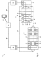
- FIG. 1 shows schematically a ring spinning system 1 according to the invention.
- the ring spinning system 1 contains a ring spinning machine 2 and a dishwasher 3.
- the ring spinning machine 2 has a large number of spinning positions 21. At each spinning point 21, yarn is spun from roving using the known ring spinning process and wound up into a so-called cop 91.
- the ring spinning machine 2 is equipped with a spinning monitoring system 4 for monitoring the operation of the spinning stations 21, e.g. B. equipped to detect thread breaks or “slow spindles”.
- the spinning monitoring system 4 contains a spinning sensor 41 at each of the spinning points 21.
- the spinning sensor 41 measures a spinning measurement variable.
- Each spinning sensor 41 is connected to a spinning monitoring control unit 43 via a wired or wireless first data line 42.
- the spinning sensor 41 sends values of the spinning measurement variable to the spinning monitoring control unit 43 via the first data line 42.
- the spinning monitoring control unit 43 receives the values. From this, it determines values of a parameter that is characteristic of the operation of the spinning station 21 for at least two different times during the winding of the cop 91 and stores the determined values together with associated first section information, which identifies the yarn sections wound up at the at least two different times, as spinning data.
- the parameters that are characteristic of the operation of the spinning station 21 are a number of thread breaks per unit of time, a ring rotor speed, an air temperature and an air humidity.
- the spinning data may relate to a particular cop 91 or to a group of cops 91 being produced at the same time, e.g. B. on cops 91 of several spinning stations 21 of the ring spinning machine 2 with the same article or on the cops 91 of all spinning stations 21 of the ring spinning machine 2. If the spinning data relate to a group of cops 91, an average value is determined for each of the at least two different times Values of all cops 91 in the group are calculated, and these average values are stored together with associated first section information as spinning data.
- the full cops 91 which are produced at the same time, are simultaneously deposited ("doffed") from the ring spinning machine 2 and then automatically transported to the winding machine 3, which in Figure 1 is indicated by dashed arrows 22.
- the winding machine 3 has a large number of winding units 31. At each winding station 31, yarn 92 is successively placed on a yarn spool 93 by several cops 91, e.g. B. a cross-wound bobbin, rewound.
- the dishwasher 3 is equipped with a yarn monitoring system 5 for monitoring properties of the yarn 92.
- the yarn monitoring system 5 includes a yarn sensor 51 at each of the winding stations.
- the yarn sensor 51 measures a yarn measurement variable.
- Each yarn sensor 51 is connected to a yarn monitoring control unit 53 via a wired or wireless second data line 52.
- the yarn sensor 51 sends values of the yarn measurement variable to the yarn monitoring control unit 53 via the second data line 52.
- the yarn monitoring control unit 53 receives the values.
- the yarn monitoring system 5 can z. B. can be designed as a yarn cleaner system, with each yarn sensor 51 being assigned a yarn cutting unit which removes unacceptable yarn defects from the yarn 92.
- the yarn data relates to the same cop 91 or to the same group of cops 91 as the spinning data. If the spinning data relates to a group of cops 91, an average of the values of all cops 91 in the group is calculated for each of the at least two different times, and these average values are stored together with associated second section information as yarn data.
- the ring spinning system 1 further includes a central control and evaluation device 6.
- the central control and evaluation device 6 is connected to the spinning monitoring control unit 43 via a wired or wireless third data line 44 and receives the spinning data from it.
- the central control and evaluation device 6 is also connected to the yarn monitoring control unit 53 via a wired or wireless fourth data line 54 and receives the yarn data from it.
- the central control and evaluation device 6 assigns the received spinning data and yarn data to one another based on the respective first and second section information in such a way that they relate to the same yarn section. It thereby provides a basis for an intervention on the ring spinning machine 2.
- the spinning data and yarn data to be assigned to one another must relate to the same cop 91 or to the same group of cops 91.
- Unwinding the cop 91 or the group of cops 91 is assigned to the cop 91 or the group of cops 91 and is stored as a key with both the spinning data and the yarn data.
- Such an identification of a point in time when the cop 91 or the group of cops 91 is unwrapped can, for. B. be a so-called doff number, ie a natural number that uniquely identifies a doffing ("doff") of simultaneously produced cops 91 from the ring spinning machine 2 and which is increased by one with each subsequent doff.
- the ring spinning system 1 is preferably equipped with a cop tracking system (not shown), which makes it possible to assign a cop 91 located in the dishwasher 3 to the spinning station 21 on which it was produced.
- a cop tracking system can be used for the above-mentioned identification of a point in time when the cop 91 or the group of cops 91 is unwrapped. It can provide the identification of the central control and evaluation device 6. In addition, it can assign an identification of the spinning station 21 on which a specific cop 91 was produced to the cop 91 and provide the assignment of the central control and evaluation device 6.
- the central control and evaluation device 6 can also store this identification as a key with both the spinning data and the yarn data in order to enable or facilitate the mutual assignment of the spinning data and the yarn data.
- the central control and evaluation device 6 can be designed as an independent device, e.g. B. as a computer that is located in the spinning mill or outside the spinning mill. Alternatively, the central control and evaluation device 6 can be integrated in another device, e.g. B. in a yarn testing device in the textile laboratory of the spinning mill, in the spinning monitoring control unit 43, in the yarn monitoring control unit 53 etc. In the latter two cases, there can be a direct data connection between the spinning monitoring control unit 43 and the yarn monitoring control unit 53, via which the two control units 43, 53 transmit data or exchange.
- the central control and evaluation device 6 is preferably connected to an input unit and/or an output unit which an operator can make inputs or receive outputs.
- a mobile device 61 e.g. B. a mobile phone, which communicates wirelessly with the central control and evaluation device 6, shown as an input and output unit.
- other known input units such as. B. a computer keyboard and output units such as. B. a computer screen can be used.
- the ring spinning system 1 includes several spinning monitoring systems 4 on one or more ring spinning machines 2, the spinning monitoring control units 43 of which are connected to a spinning expert system 45.
- the spinning expert system 45 is set up to receive, process and output data from the spinning monitoring control units 43 in a suitable form, as well as to control the spinning monitoring control units 43. It is in turn connected to the central control and evaluation device 6.
- the ring spinning system 1 includes several yarn monitoring systems 5 on one or more winding machines 3, the yarn monitoring control units 53 of which are connected to a yarn expert system 55.
- the gaming expert system 55 is set up to receive data from the yarn monitoring control units 53, process it and output it in a suitable form, as well as to control the yarn monitoring control units 53. It is in turn connected to the central control and evaluation device 6.
- the mutual assignment of the spinning data and the yarn data provides a basis for an intervention on the ring spinning machine 2.
- an intervention can take place automatically.
- the intervention can be carried out by an operator.
- the spinning data and yarn data assigned to one another are graphically displayed together, and the graphical representation of the spinning data and yarn data assigned to one another is used in a visually detectable form as the basis for the intervention to be carried out on the Ring spinning machine 2 issued to the operator. Examples of graphical representations are in the Figures 2-4 specified.
- Figure 2 shows a first example of a graphical representation 200 of the associated spinning data and yarn data, as it can be output to an operator in a visually detectable form.
- the output takes place on a known output unit connected to the central control and evaluation device 6, for example the mobile device 61 (see Figure 1 ).
- the representation 200 includes a schematic representation 210 of a cop 291 that was wound up from bottom to top.
- the vertical axes 221, 231, 241 thus essentially indicate a time course during which the cop 291 was wound up. But you can also specify a time course during the rewinding of the cop 291, a position along the longitudinal axis of the cop 291, a length of the yarn wound on the cop 291, a mass of the yarn wound on the cop 291, etc.
- An axis 211 with two different divisions drawn in the cop 291 indicates that there are several different, but essentially corresponding, options for defining the independent variables plotted along the vertical axes 221, 231, 241.
- a number of thread breaks per unit of time 222 is shown as a function of the time 221 during the winding of the cop 291 with bars 223.
- Each bar 223 corresponds to a certain unit of time during winding, for example 20 minutes, or a certain length of yarn, for example 250 m.
- This first diagram 220 represents spinning data.
- a time course of a ring rotor speed 232 during cop production is shown with a line 233.
- the ring runner is accelerated evenly. After reaching a predetermined speed, this is essentially used for the rest of the cop production maintained.
- the speed is slowed down to zero.
- the ring rotor speed can be determined in various ways, e.g. B. from a signal from the spinning sensor 41 (see Figure 1 ) or from the speed of a rotor of a motor driving the spindle.
- This second diagram 230 also represents spinning data.
- a number of yarn errors per unit of time 242 is shown as a function of time 241 during the rewinding of the cop with bars 243, the time axis 241 being scaled so that the total rewinding time is equal to the total cop production time.
- Each bar 243 corresponds to a specific one Unit of time, for example 40 seconds when rewinding or 40 minutes when winding, or a specific length of yarn, for example 1000 m.
- Each bar 243 is in the exemplary embodiment of Figure 2 divided into three areas 244-246 representing different types of yarn defects, e.g. B. Neps 244, thin places 245 and thick places 246.
- This third diagram 240 represents yarn data, which is thus assigned to the spinning data of the first diagram 220 and the second diagram 230, in such a way that they each relate to the same yarn section.
- the dependent variables shown in the three diagrams 220, 230, 240 can relate to a single cop or to a group of cops. In the latter case, the diagrams 220, 230, 240 each show mean values of the respective variables obtained from averaging over the entire group.
- the time-resolved, mutually assigned and possibly graphically displayed spinning data and yarn data allow the ring spinning process to be optimized. Based on the associated spinning data and yarn data, it can be assessed whether and, if so, what kind of intervention needs to be carried out on the ring spinning machine 2.
- Such an intervention can include, for example, a change in a specification for a spindle speed, a replacement of a ring rotor, a replacement of a stretching belt, a replacement of a printing cylinder, a change in the air temperature and/or a change in the humidity.
- a recommendation for intervention on the ring spinning machine 2 can be automatically generated and issued to the operator.
- the recommendation can be output in a visually detectable form, for example as text in the graphical representation 200, or in another form, for example acoustically.
- each of these diagrams 250, 260, 270 shows a bar 251, 261, 271.
- Each bar 251, 261, 271 is divided into three areas, which can, for example, have the traffic light colors green, yellow or red.
- An arrow 252, 262, 272 below the bar 251, 261, 271 indicates the period of use of the component and moves from left to right along a time axis 280 as the period of use increases. If the arrow 252, 262, 272 is in the first green area, the component is relatively new and should function properly.
- the component should be replaced occasionally.
- the arrow 252, 262, 272 in the third, red area indicates that the average service life of the component has been exceeded and the component must be replaced as soon as possible.
- the components whose service life is displayed can e.g. B. the ring runner, the printing cylinder or the stretching strap of the spinning station.
- these diagrams 250, 260, 270 can relate to a single cop or to a group of cops. Such diagrams can additionally support the decision about a possible intervention on the ring spinning machine 2.
- a frame 290 comprising all elements of the representation 200 indicates the visual comprehensibility of the graphic representation 200.
- the diagrams 220, 230, 240, which represent the associated spinning data and yarn data should be displayed simultaneously and close to each other, e.g. B. on the same screen page.
- Figure 3 shows a similar situation as Figure 2 , and corresponding elements are designated by analogous reference numerals.
- Diagrams 320, 330, 340 refer to two cops wound at different times. They each show a first, solid line 323.1, 333.1 or 343.1, which refers to a first cop, and a second, dashed line 323.2, 333.2 or 343.2, which refers to a second cop. Without loss of generality, we can assume that the second cop was wound up after the first cop.
- the first diagram 320 is divided into two areas 325, 326 by a straight line 324 parallel to the time axis 321, which determine the requirements for the productivity of the spinning station 21.
- a first area 325 the number of thread breaks per unit of time 322 is permissible, in a second area 326 it is impermissible.
- the first two parameter values of the first cop (line 323.1) and the first parameter value of the second cop (line 323.2) are invalid.
- the third diagram 340 is divided into three areas 346-348 by two straight lines 344, 345 parallel to the time axis 341, which determine the quality requirements for the yarn 92.
- a first area 346 the number of yarn defects per unit of time 342 is so small that the quality requirements are significantly exceeded, which presumably affects productivity. Therefore, a number of yarn defects per unit of time 342 in this first area 346 is undesirable. It is optimal if the number of yarn defects per unit of time 342 lies in a second range 347.
- the number of yarn defects per unit of time 342 is too high and therefore inadmissible.
- the first parameter value of the first cop (line 343.1) is invalid.
- FIG. 4 Another graphical representation of the associated spinning data and yarn data shows Figure 4 .
- the two-dimensional diagram 400 is spanned by the parameter 411, which is characteristic of the operation of the spinning station, on the one hand, and by the parameter 412, which is characteristic of the yarn, on the other hand.
- the values of these two parameters form coordinates of points 421.1, 421.2, which are shown in diagram 400. If the number and/or location of the corresponding ones in the Figures 2 and 3 If the parameter values shown do not match, the relevant values can be determined by interpolation and/or extrapolation of the existing values.
- the chart 400 of Figure 4 contains in contrast to the diagrams of the Figures 2 and 3 no axis corresponding to time. However, the time course can be indicated by arrows 422.1, 422.2 between two consecutive points.
- the diagram 400 is divided into six areas 431-436 by axially parallel straight lines 413-415. This division corresponds to that of Figure 3 , where the first diagram 320 is divided by the straight line 324 and the third diagram 340 by the straight lines 344, 345.
- B points that lie in the area 433, both a permissible parameter 411 characteristic of the spinning position and a permissible parameter 412 characteristic of the yarn;
- Points in area 434 have a permissible parameter 412 characteristic of the yarn, but an impermissible parameter 411 characteristic of the spinning position; etc.
- Examples of a possible intervention on the ring spinning machine 2 are given below, as they can be carried out according to the invention on the basis of the spinning data and yarn data assigned to one another.
- the intervention can be carried out automatically by the central control and evaluation device 6 or manually by an operator.
- the central control and evaluation device 6 is connected to a control unit of the ring spinning machine 2 and transmits corresponding control signals to it.
- a control unit of the ring spinning machine 2 is in Figure 1 not marked separately. In one embodiment, it may coincide with the spinning monitoring control unit 43.
- one or more recommendations for the intervention can at least be generated automatically and output to the operator in addition to the graphical display.
- a recommendation can include several options, e.g. E.g.: “Reduce the ring rotor speed or replace the stretching belt!”
- the first two parameter values of the first cop (line 323.1) are in the impermissible range 326.
- the first parameter value of the same cop in the third diagram 340 is also in the impermissible range 348.
- the reason for the impermissible parameter values may be that the increase is too rapid the speed of the ring rotor at the start of winding.
- the acceleration of the ring traveler at the start of winding is reduced as an intervention on the ring spinning machine 2.
- the final speed can be set slightly higher.
- the speed profile 333.2 which has been changed compared to the original speed profile 333.1, is in the second diagram 330 of Figure 3 shown.
- the effects of this intervention are checked based on the associated spinning data and yarn data. This is possible as soon as a second cop has been wound up at the same spinning station 21 as the first cop with the second speed profile 333.2 and rewound at any winding station 31.
- the spinning data of the second cop is shown in the first diagram 320 with the line 323.2, the yarn data in the third diagram 340 with the line 343.2.
- the yarn data are now all within the permissible range 347. Thanks to the intervention, it was achieved that the yarn quality on the second cop is essentially the same, while on the first cop it was much worse at the bottom of the cop than at the top.
- the first parameter value of the spinning data for the second cop is still in the impermissible range 326.
- further intervention can be carried out. This can e.g. B. consist in a further reduction in the acceleration of the ring rotor at the start of winding or in replacing the ring rotor. Care is taken to ensure that the yarn data remains within the permissible range 347.
- Each of the six areas 431-436 can be assigned a specific intervention on the ring spinning machine 2.
- the intervention can depend on at what time or at what location on the cop the relevant parameter values were determined. If e.g. B. points in the area 436, an intervention can be provided to reduce the speed of the ring rotor at the relevant time during winding. For points in area 434, replacement of the ring rotor can be provided as an intervention if this is due (pointer 352 in diagram 350 of Figure 3 in the second or third area of the bar 351), otherwise a reduction in the speed of the ring rotor at the relevant time. No intervention is necessary for points in the 433 area.
- the controlled variables are the parameter characteristic of the operation of the spinning station 21 and/or the parameter characteristic of the yarn.
- the desired state is that the parameter values are in the permissible ranges 325, 347 ( Figure 3 ) or 433 ( Figure 4 ) lay. If this is not the case, a specific intervention is carried out on the ring spinning machine 2 as a control intervention.
- the control takes place relatively slowly because it takes at least the time required for winding up a cop ("doff time") until the effect of the control intervention can be checked and, if necessary, a new control intervention can be made. Nevertheless, the regulation according to the invention solves the problem set at the beginning.
Landscapes
- Engineering & Computer Science (AREA)
- Mechanical Engineering (AREA)
- Textile Engineering (AREA)
- Quality & Reliability (AREA)
- Spinning Or Twisting Of Yarns (AREA)
- Filamentary Materials, Packages, And Safety Devices Therefor (AREA)
Applications Claiming Priority (2)
| Application Number | Priority Date | Filing Date | Title |
|---|---|---|---|
| CH6742018 | 2018-05-28 | ||
| PCT/CH2019/000016 WO2019227241A1 (de) | 2018-05-28 | 2019-05-27 | Ringspinnanlage und verfahren zu ihrem betrieb |
Publications (2)
| Publication Number | Publication Date |
|---|---|
| EP3802927A1 EP3802927A1 (de) | 2021-04-14 |
| EP3802927B1 true EP3802927B1 (de) | 2023-10-04 |
Family
ID=62528179
Family Applications (1)
| Application Number | Title | Priority Date | Filing Date |
|---|---|---|---|
| EP19727923.5A Active EP3802927B1 (de) | 2018-05-28 | 2019-05-27 | Ringspinnanlage und verfahren zu ihrem betrieb |
Country Status (5)
| Country | Link |
|---|---|
| US (1) | US11319649B2 (https=) |
| EP (1) | EP3802927B1 (https=) |
| JP (1) | JP7316303B2 (https=) |
| CN (1) | CN112204179B (https=) |
| WO (1) | WO2019227241A1 (https=) |
Families Citing this family (12)
| Publication number | Priority date | Publication date | Assignee | Title |
|---|---|---|---|---|
| DE102019116627A1 (de) * | 2019-06-19 | 2020-12-24 | Saurer Spinning Solutions Gmbh & Co. Kg | Textilmaschine mit mehreren Arbeitsstellen sowie Verfahren zur Überwachung einer Textilmaschine mit mehreren Arbeitsstellen |
| EP3904572B1 (en) * | 2020-04-30 | 2022-04-06 | Maschinenfabrik Rieter AG | Device and method for detecting a fault in a spinning mill and for estimating one or more sources of the fault |
| IT202000024097A1 (it) * | 2020-10-13 | 2022-04-13 | Savio Macch Tessili Spa | Sistema e procedimento per la gestione di un impianto tessile |
| EP4105368A1 (en) * | 2021-06-16 | 2022-12-21 | Maschinenfabrik Rieter AG | Device and method for enabling displaying on a user display an operating readiness index related to a spinning mill |
| ES2932482B2 (es) * | 2021-07-09 | 2023-05-19 | Gp Tecnic Sl | Maquina bobinadora para carretes de rafia |
| CN113620119B (zh) * | 2021-08-31 | 2023-03-24 | 上海兰宝传感科技股份有限公司 | 一种纱管数量检测系统及其方法 |
| EP4163242A1 (en) * | 2021-10-08 | 2023-04-12 | Maschinenfabrik Rieter AG | An electronic device for locating a functional disorder at a spinning and winding section of a spinning mill and a method for locating the same |
| EP4170076A1 (en) | 2021-10-22 | 2023-04-26 | Maschinenfabrik Rieter AG | An electronic device for adjusting operational parameters of a winding machine of a spinning mill and a method for adjusting the same |
| CN114742429A (zh) * | 2022-04-21 | 2022-07-12 | 乌斯特技术股份公司 | 由计算机实现的用于评估纺纱厂的方法 |
| CN116957706A (zh) * | 2022-04-21 | 2023-10-27 | 乌斯特技术股份公司 | 由计算机实现的用于纱线包交易的方法 |
| DE102022121517A1 (de) * | 2022-08-25 | 2024-03-07 | Maschinenfabrik Rieter Ag | Verfahren zum Betreiben einer Textilmaschine |
| EP4474536A1 (en) * | 2023-06-07 | 2024-12-11 | Rieter AG | Spinning controller for a spinning machine and method for controlling a spinning machine |
Family Cites Families (27)
| Publication number | Priority date | Publication date | Assignee | Title |
|---|---|---|---|---|
| DE2815162C3 (de) | 1978-04-07 | 1981-09-17 | Agfa-Gevaert Ag, 5090 Leverkusen | Durchlauf-Entwicklungsmaschine |
| JPS5862511A (ja) * | 1981-10-09 | 1983-04-14 | Murata Mach Ltd | 糸ムラ情報の解析方法および解析装置 |
| JPS61178375A (ja) | 1985-01-31 | 1986-08-11 | Murata Mach Ltd | 精紡機の管理システム |
| DE3712654A1 (de) * | 1987-04-14 | 1988-10-27 | Schlafhorst & Co W | Verfahren zum ueberwachen der qualitaet von produktionsstellen, garnen und spulen an einem maschinenverbund aus wenigstens einer ringspinnmaschine und wenigstens einem spulautomaten |
| IT1229538B (it) | 1988-01-25 | 1991-09-04 | Murata Machinery Ltd | Metodo di conduzione di un filatoio e di rivelazione di bobine difettose |
| DE3911799A1 (de) * | 1989-04-11 | 1990-10-18 | Schlafhorst & Co W | Informationssystem innerhalb eines verbundes zwischen je einer oder mehreren spinn- und spulmaschinen |
| JPH047269A (ja) * | 1990-04-24 | 1992-01-10 | Murata Mach Ltd | 紡績工場における品質管理システム |
| CH685202A5 (de) * | 1991-03-07 | 1995-04-28 | Rieter Ag Maschf | Verfahren zum Steuern einer vernetzten Spinnereianlage. |
| DE4306095A1 (de) | 1992-03-04 | 1993-10-07 | Rieter Ag Maschf | Verfahren und Einrichtung zum Steuern einer vernetzten Anlage |
| DE4209203B4 (de) | 1992-03-21 | 2005-11-03 | Saurer Gmbh & Co. Kg | Spinn-/Spulmaschinenkombination mit einer Vorrichtung zum Überwachen des ordnungsgemäßen Arbeitens der einzelnen Spinnstellen |
| CH684488A5 (de) * | 1992-05-20 | 1994-09-30 | Zellweger Uster Ag | Verfahren und Vorrichtung zur online Erkennung von schlecht eingestellten oder defekten Streckwerken an Ringspinnmaschinen. |
| EP0924324B1 (de) * | 1997-12-17 | 2002-09-04 | Zellweger Luwa Ag | Vorrichtung zur Ueberwachung von Garnen an Ringspinnmaschinen |
| DE10062479A1 (de) * | 2000-12-14 | 2002-06-20 | Schlafhorst & Co W | Verfahren zum Spulen des laufenden Fadens an einer Arbeitsstelle einer Spinnspul- oder einer Spulmaschine |
| WO2007012212A1 (de) * | 2005-07-27 | 2007-02-01 | Uster Technologies Ag | Textilmaschine mit garnüberwachung |
| DE102005049436A1 (de) * | 2005-10-15 | 2007-04-19 | Saurer Gmbh & Co. Kg | Verfahren zum Betreiben einer Textilmaschine |
| JP5354343B2 (ja) * | 2005-11-18 | 2013-11-27 | ウステル・テヒノロジーズ・アクチエンゲゼルシヤフト | ファンシーヤーンの特徴付け方法 |
| EP2017376A1 (de) * | 2007-07-16 | 2009-01-21 | Maschinenfabrik Rieter Ag | Verfahren zum Betreiben einer Spinnmaschine |
| DE102007039049A1 (de) * | 2007-08-17 | 2009-02-19 | Oerlikon Textile Gmbh & Co. Kg | Spinnanlage |
| EP2217746A1 (de) | 2007-12-13 | 2010-08-18 | Uster Technologies AG | Vorrichtung und verfahren zur überwachung einer mehrzahl von arbeitsstellen einer ringspinnmaschine |
| CH699219A1 (de) * | 2008-07-25 | 2010-01-29 | Uster Technologies Ag | Verfahren und Vorrichtung zur Garnreinigung. |
| CN103270413A (zh) | 2010-10-19 | 2013-08-28 | 乌斯特技术股份公司 | 清纱器和用于清纱的方法 |
| JP2014514225A (ja) * | 2011-03-16 | 2014-06-19 | ウステル・テヒノロジーズ・アクチエンゲゼルシヤフト | 繊維供試品の特徴づけ |
| JP2014024613A (ja) * | 2012-07-24 | 2014-02-06 | Murata Mach Ltd | 糸監視装置、糸巻取ユニット、及び、糸巻取機 |
| US8804452B2 (en) | 2012-07-31 | 2014-08-12 | Micron Technology, Inc. | Data interleaving module |
| US9444509B2 (en) | 2012-09-27 | 2016-09-13 | Intel Corporation | Non-blocking power management for on-package input/output architectures |
| JP2017001781A (ja) * | 2015-06-05 | 2017-01-05 | 村田機械株式会社 | 糸巻取システム、自動ワインダ、精紡機及び糸巻取方法 |
| CN107815761A (zh) | 2016-09-13 | 2018-03-20 | 第伊沃尔维克斯私人有限公司 | 用于加工连续条状纺织材料的机器的测量系统 |
-
2019
- 2019-05-27 CN CN201980036481.2A patent/CN112204179B/zh active Active
- 2019-05-27 JP JP2020566652A patent/JP7316303B2/ja active Active
- 2019-05-27 US US15/733,760 patent/US11319649B2/en active Active
- 2019-05-27 WO PCT/CH2019/000016 patent/WO2019227241A1/de not_active Ceased
- 2019-05-27 EP EP19727923.5A patent/EP3802927B1/de active Active
Also Published As
| Publication number | Publication date |
|---|---|
| CN112204179A (zh) | 2021-01-08 |
| WO2019227241A1 (de) | 2019-12-05 |
| EP3802927A1 (de) | 2021-04-14 |
| JP2021526187A (ja) | 2021-09-30 |
| US20210148012A1 (en) | 2021-05-20 |
| US11319649B2 (en) | 2022-05-03 |
| CN112204179B (zh) | 2023-07-28 |
| WO2019227241A8 (de) | 2020-12-10 |
| JP7316303B2 (ja) | 2023-07-27 |
Similar Documents
| Publication | Publication Date | Title |
|---|---|---|
| EP3802927B1 (de) | Ringspinnanlage und verfahren zu ihrem betrieb | |
| EP0513339B1 (de) | Eine Anlage mit einem Prozessleitrechner | |
| EP0541483B1 (de) | Prozess-Steuerung im Textilbetrieb | |
| DE3924779A1 (de) | Verfahren und vorrichtung zum betrieb einer spinnereilinie | |
| EP3760772B1 (de) | Optimierung des betriebes einer spinnmaschine | |
| EP2966201B1 (de) | Semiautomatische offenend-rotorspinnmaschine | |
| EP3052416B1 (de) | Garnreiniger sowie damit ausgerüstete spinnstelle einer spinnmaschine sowie verfahren zum betrieb einer spinnstelle | |
| EP3802389B1 (de) | Automatische ringspinnanlage und verfahren zu ihrem automatischen betrieb | |
| EP2955143B1 (de) | Semiautomatische kreuzspulen herstellende textilmaschine | |
| DE3635576C2 (de) | Verfahren und Anlage zum Vorgarnspulenwechsel | |
| DE4306095A1 (de) | Verfahren und Einrichtung zum Steuern einer vernetzten Anlage | |
| DE3030504C2 (de) | Verfahren und Vorrichtung zur Erzeugung von Garnspulen mit vorgegebener Garnlänge auf Rotorspinnmaschinen | |
| EP2830982B1 (de) | Verfahren zur garnüberwachung | |
| DE102007015695A1 (de) | Verfahren zum Betreiben einer Kreuzspulen herstellenden Textilmaschine | |
| EP0528003A1 (de) | Verfahren und einrichtung zum steuern einer vernetzten anlage | |
| DE102021002646A1 (de) | Verfahren zur Überwachung einer Vielzahl von Bearbeitungsstellen für synthetische Fäden | |
| EP3918119B1 (de) | Optimierung eines spinnprozesses bezüglich fremdmaterialien. | |
| CH714693A2 (de) | Verfahren zum Betrieb einer Ringspinnanlage und Ringspinnanlage. | |
| EP0512442A1 (de) | Produktionsplanung und -steuerung für eine Spinnereianlage | |
| DE102022004857A1 (de) | Verfahren zum Ermitteln der Spulenqualität einer Sammelspule | |
| CH469620A (de) | Verfahren zur Ueberwachung der Spulstellen einer automatischen Spulmaschine | |
| DE4141407A1 (de) | Verfahren zum wechseln von rohstoffgebinden | |
| DE102023109203A1 (de) | Verfahren zum Betreiben eines Textilmaschinenverbunds, Textilmaschinenverbund und Datenverarbeitungseinheit | |
| DE102021001348A1 (de) | Verfahren zur Überwachung eines Herstellungsprozesses eines synthetischen Fadens | |
| DE1710127C3 (de) | Vorrichtung zum Überwachen der Spulstellen einer automatischen Spulmaschine |
Legal Events
| Date | Code | Title | Description |
|---|---|---|---|
| STAA | Information on the status of an ep patent application or granted ep patent |
Free format text: STATUS: UNKNOWN |
|
| STAA | Information on the status of an ep patent application or granted ep patent |
Free format text: STATUS: THE INTERNATIONAL PUBLICATION HAS BEEN MADE |
|
| PUAI | Public reference made under article 153(3) epc to a published international application that has entered the european phase |
Free format text: ORIGINAL CODE: 0009012 |
|
| STAA | Information on the status of an ep patent application or granted ep patent |
Free format text: STATUS: REQUEST FOR EXAMINATION WAS MADE |
|
| 17P | Request for examination filed |
Effective date: 20210111 |
|
| AK | Designated contracting states |
Kind code of ref document: A1 Designated state(s): AL AT BE BG CH CY CZ DE DK EE ES FI FR GB GR HR HU IE IS IT LI LT LU LV MC MK MT NL NO PL PT RO RS SE SI SK SM TR |
|
| AX | Request for extension of the european patent |
Extension state: BA ME |
|
| DAV | Request for validation of the european patent (deleted) | ||
| DAX | Request for extension of the european patent (deleted) | ||
| GRAP | Despatch of communication of intention to grant a patent |
Free format text: ORIGINAL CODE: EPIDOSNIGR1 |
|
| STAA | Information on the status of an ep patent application or granted ep patent |
Free format text: STATUS: GRANT OF PATENT IS INTENDED |
|
| INTG | Intention to grant announced |
Effective date: 20230316 |
|
| RIN1 | Information on inventor provided before grant (corrected) |
Inventor name: GEITER, PAUL Inventor name: EGGIMANN, KURT Inventor name: BIRSENER, ANDREAS Inventor name: NARAYANAN, SIVAKUMAR Inventor name: ARCHONTOPOULOS, VASILEIOS |
|
| GRAJ | Information related to disapproval of communication of intention to grant by the applicant or resumption of examination proceedings by the epo deleted |
Free format text: ORIGINAL CODE: EPIDOSDIGR1 |
|
| STAA | Information on the status of an ep patent application or granted ep patent |
Free format text: STATUS: REQUEST FOR EXAMINATION WAS MADE |
|
| INTC | Intention to grant announced (deleted) | ||
| RIN1 | Information on inventor provided before grant (corrected) |
Inventor name: GEITER, PAUL Inventor name: EGGIMANN, KURT Inventor name: BIRSNER, ANDREAS Inventor name: NARAYANAN, SIVAKUMAR Inventor name: ARCHONTOPOULOS, VASILEIOS |
|
| GRAP | Despatch of communication of intention to grant a patent |
Free format text: ORIGINAL CODE: EPIDOSNIGR1 |
|
| STAA | Information on the status of an ep patent application or granted ep patent |
Free format text: STATUS: GRANT OF PATENT IS INTENDED |
|
| GRAS | Grant fee paid |
Free format text: ORIGINAL CODE: EPIDOSNIGR3 |
|
| GRAA | (expected) grant |
Free format text: ORIGINAL CODE: 0009210 |
|
| STAA | Information on the status of an ep patent application or granted ep patent |
Free format text: STATUS: THE PATENT HAS BEEN GRANTED |
|
| INTG | Intention to grant announced |
Effective date: 20230808 |
|
| AK | Designated contracting states |
Kind code of ref document: B1 Designated state(s): AL AT BE BG CH CY CZ DE DK EE ES FI FR GB GR HR HU IE IS IT LI LT LU LV MC MK MT NL NO PL PT RO RS SE SI SK SM TR |
|
| REG | Reference to a national code |
Ref country code: GB Ref legal event code: FG4D Free format text: NOT ENGLISH |
|
| REG | Reference to a national code |
Ref country code: CH Ref legal event code: EP |
|
| REG | Reference to a national code |
Ref country code: DE Ref legal event code: R096 Ref document number: 502019009561 Country of ref document: DE |
|
| REG | Reference to a national code |
Ref country code: IE Ref legal event code: FG4D Free format text: LANGUAGE OF EP DOCUMENT: GERMAN |
|
| REG | Reference to a national code |
Ref country code: LT Ref legal event code: MG9D |
|
| REG | Reference to a national code |
Ref country code: NL Ref legal event code: MP Effective date: 20231004 |
|
| PG25 | Lapsed in a contracting state [announced via postgrant information from national office to epo] |
Ref country code: NL Free format text: LAPSE BECAUSE OF FAILURE TO SUBMIT A TRANSLATION OF THE DESCRIPTION OR TO PAY THE FEE WITHIN THE PRESCRIBED TIME-LIMIT Effective date: 20231004 |
|
| PG25 | Lapsed in a contracting state [announced via postgrant information from national office to epo] |
Ref country code: GR Free format text: LAPSE BECAUSE OF FAILURE TO SUBMIT A TRANSLATION OF THE DESCRIPTION OR TO PAY THE FEE WITHIN THE PRESCRIBED TIME-LIMIT Effective date: 20240105 |
|
| PG25 | Lapsed in a contracting state [announced via postgrant information from national office to epo] |
Ref country code: IS Free format text: LAPSE BECAUSE OF FAILURE TO SUBMIT A TRANSLATION OF THE DESCRIPTION OR TO PAY THE FEE WITHIN THE PRESCRIBED TIME-LIMIT Effective date: 20240204 |
|
| PG25 | Lapsed in a contracting state [announced via postgrant information from national office to epo] |
Ref country code: LT Free format text: LAPSE BECAUSE OF FAILURE TO SUBMIT A TRANSLATION OF THE DESCRIPTION OR TO PAY THE FEE WITHIN THE PRESCRIBED TIME-LIMIT Effective date: 20231004 |
|
| P01 | Opt-out of the competence of the unified patent court (upc) registered |
Effective date: 20240312 |
|
| PG25 | Lapsed in a contracting state [announced via postgrant information from national office to epo] |
Ref country code: ES Free format text: LAPSE BECAUSE OF FAILURE TO SUBMIT A TRANSLATION OF THE DESCRIPTION OR TO PAY THE FEE WITHIN THE PRESCRIBED TIME-LIMIT Effective date: 20231004 |
|
| PG25 | Lapsed in a contracting state [announced via postgrant information from national office to epo] |
Ref country code: LT Free format text: LAPSE BECAUSE OF FAILURE TO SUBMIT A TRANSLATION OF THE DESCRIPTION OR TO PAY THE FEE WITHIN THE PRESCRIBED TIME-LIMIT Effective date: 20231004 Ref country code: IS Free format text: LAPSE BECAUSE OF FAILURE TO SUBMIT A TRANSLATION OF THE DESCRIPTION OR TO PAY THE FEE WITHIN THE PRESCRIBED TIME-LIMIT Effective date: 20240204 Ref country code: GR Free format text: LAPSE BECAUSE OF FAILURE TO SUBMIT A TRANSLATION OF THE DESCRIPTION OR TO PAY THE FEE WITHIN THE PRESCRIBED TIME-LIMIT Effective date: 20240105 Ref country code: ES Free format text: LAPSE BECAUSE OF FAILURE TO SUBMIT A TRANSLATION OF THE DESCRIPTION OR TO PAY THE FEE WITHIN THE PRESCRIBED TIME-LIMIT Effective date: 20231004 Ref country code: BG Free format text: LAPSE BECAUSE OF FAILURE TO SUBMIT A TRANSLATION OF THE DESCRIPTION OR TO PAY THE FEE WITHIN THE PRESCRIBED TIME-LIMIT Effective date: 20240104 Ref country code: PT Free format text: LAPSE BECAUSE OF FAILURE TO SUBMIT A TRANSLATION OF THE DESCRIPTION OR TO PAY THE FEE WITHIN THE PRESCRIBED TIME-LIMIT Effective date: 20240205 |
|
| PG25 | Lapsed in a contracting state [announced via postgrant information from national office to epo] |
Ref country code: SE Free format text: LAPSE BECAUSE OF FAILURE TO SUBMIT A TRANSLATION OF THE DESCRIPTION OR TO PAY THE FEE WITHIN THE PRESCRIBED TIME-LIMIT Effective date: 20231004 Ref country code: RS Free format text: LAPSE BECAUSE OF FAILURE TO SUBMIT A TRANSLATION OF THE DESCRIPTION OR TO PAY THE FEE WITHIN THE PRESCRIBED TIME-LIMIT Effective date: 20231004 Ref country code: PL Free format text: LAPSE BECAUSE OF FAILURE TO SUBMIT A TRANSLATION OF THE DESCRIPTION OR TO PAY THE FEE WITHIN THE PRESCRIBED TIME-LIMIT Effective date: 20231004 Ref country code: NO Free format text: LAPSE BECAUSE OF FAILURE TO SUBMIT A TRANSLATION OF THE DESCRIPTION OR TO PAY THE FEE WITHIN THE PRESCRIBED TIME-LIMIT Effective date: 20240104 Ref country code: LV Free format text: LAPSE BECAUSE OF FAILURE TO SUBMIT A TRANSLATION OF THE DESCRIPTION OR TO PAY THE FEE WITHIN THE PRESCRIBED TIME-LIMIT Effective date: 20231004 Ref country code: HR Free format text: LAPSE BECAUSE OF FAILURE TO SUBMIT A TRANSLATION OF THE DESCRIPTION OR TO PAY THE FEE WITHIN THE PRESCRIBED TIME-LIMIT Effective date: 20231004 |
|
| REG | Reference to a national code |
Ref country code: DE Ref legal event code: R097 Ref document number: 502019009561 Country of ref document: DE |
|
| PG25 | Lapsed in a contracting state [announced via postgrant information from national office to epo] |
Ref country code: DK Free format text: LAPSE BECAUSE OF FAILURE TO SUBMIT A TRANSLATION OF THE DESCRIPTION OR TO PAY THE FEE WITHIN THE PRESCRIBED TIME-LIMIT Effective date: 20231004 |
|
| PG25 | Lapsed in a contracting state [announced via postgrant information from national office to epo] |
Ref country code: CZ Free format text: LAPSE BECAUSE OF FAILURE TO SUBMIT A TRANSLATION OF THE DESCRIPTION OR TO PAY THE FEE WITHIN THE PRESCRIBED TIME-LIMIT Effective date: 20231004 |
|
| PG25 | Lapsed in a contracting state [announced via postgrant information from national office to epo] |
Ref country code: SK Free format text: LAPSE BECAUSE OF FAILURE TO SUBMIT A TRANSLATION OF THE DESCRIPTION OR TO PAY THE FEE WITHIN THE PRESCRIBED TIME-LIMIT Effective date: 20231004 |
|
| PG25 | Lapsed in a contracting state [announced via postgrant information from national office to epo] |
Ref country code: SM Free format text: LAPSE BECAUSE OF FAILURE TO SUBMIT A TRANSLATION OF THE DESCRIPTION OR TO PAY THE FEE WITHIN THE PRESCRIBED TIME-LIMIT Effective date: 20231004 Ref country code: SK Free format text: LAPSE BECAUSE OF FAILURE TO SUBMIT A TRANSLATION OF THE DESCRIPTION OR TO PAY THE FEE WITHIN THE PRESCRIBED TIME-LIMIT Effective date: 20231004 Ref country code: RO Free format text: LAPSE BECAUSE OF FAILURE TO SUBMIT A TRANSLATION OF THE DESCRIPTION OR TO PAY THE FEE WITHIN THE PRESCRIBED TIME-LIMIT Effective date: 20231004 Ref country code: EE Free format text: LAPSE BECAUSE OF FAILURE TO SUBMIT A TRANSLATION OF THE DESCRIPTION OR TO PAY THE FEE WITHIN THE PRESCRIBED TIME-LIMIT Effective date: 20231004 Ref country code: DK Free format text: LAPSE BECAUSE OF FAILURE TO SUBMIT A TRANSLATION OF THE DESCRIPTION OR TO PAY THE FEE WITHIN THE PRESCRIBED TIME-LIMIT Effective date: 20231004 Ref country code: CZ Free format text: LAPSE BECAUSE OF FAILURE TO SUBMIT A TRANSLATION OF THE DESCRIPTION OR TO PAY THE FEE WITHIN THE PRESCRIBED TIME-LIMIT Effective date: 20231004 |
|
| PLBE | No opposition filed within time limit |
Free format text: ORIGINAL CODE: 0009261 |
|
| STAA | Information on the status of an ep patent application or granted ep patent |
Free format text: STATUS: NO OPPOSITION FILED WITHIN TIME LIMIT |
|
| 26N | No opposition filed |
Effective date: 20240705 |
|
| PG25 | Lapsed in a contracting state [announced via postgrant information from national office to epo] |
Ref country code: SI Free format text: LAPSE BECAUSE OF FAILURE TO SUBMIT A TRANSLATION OF THE DESCRIPTION OR TO PAY THE FEE WITHIN THE PRESCRIBED TIME-LIMIT Effective date: 20231004 |
|
| PG25 | Lapsed in a contracting state [announced via postgrant information from national office to epo] |
Ref country code: SI Free format text: LAPSE BECAUSE OF FAILURE TO SUBMIT A TRANSLATION OF THE DESCRIPTION OR TO PAY THE FEE WITHIN THE PRESCRIBED TIME-LIMIT Effective date: 20231004 |
|
| PG25 | Lapsed in a contracting state [announced via postgrant information from national office to epo] |
Ref country code: MC Free format text: LAPSE BECAUSE OF FAILURE TO SUBMIT A TRANSLATION OF THE DESCRIPTION OR TO PAY THE FEE WITHIN THE PRESCRIBED TIME-LIMIT Effective date: 20231004 |
|
| PG25 | Lapsed in a contracting state [announced via postgrant information from national office to epo] |
Ref country code: LU Free format text: LAPSE BECAUSE OF NON-PAYMENT OF DUE FEES Effective date: 20240527 |
|
| GBPC | Gb: european patent ceased through non-payment of renewal fee |
Effective date: 20240527 |
|
| PG25 | Lapsed in a contracting state [announced via postgrant information from national office to epo] |
Ref country code: MC Free format text: LAPSE BECAUSE OF FAILURE TO SUBMIT A TRANSLATION OF THE DESCRIPTION OR TO PAY THE FEE WITHIN THE PRESCRIBED TIME-LIMIT Effective date: 20231004 Ref country code: LU Free format text: LAPSE BECAUSE OF NON-PAYMENT OF DUE FEES Effective date: 20240527 |
|
| REG | Reference to a national code |
Ref country code: BE Ref legal event code: MM Effective date: 20240531 |
|
| PG25 | Lapsed in a contracting state [announced via postgrant information from national office to epo] |
Ref country code: IE Free format text: LAPSE BECAUSE OF NON-PAYMENT OF DUE FEES Effective date: 20240527 |
|
| PG25 | Lapsed in a contracting state [announced via postgrant information from national office to epo] |
Ref country code: BE Free format text: LAPSE BECAUSE OF NON-PAYMENT OF DUE FEES Effective date: 20240531 |
|
| PG25 | Lapsed in a contracting state [announced via postgrant information from national office to epo] |
Ref country code: FR Free format text: LAPSE BECAUSE OF NON-PAYMENT OF DUE FEES Effective date: 20240531 |
|
| PG25 | Lapsed in a contracting state [announced via postgrant information from national office to epo] |
Ref country code: GB Free format text: LAPSE BECAUSE OF NON-PAYMENT OF DUE FEES Effective date: 20240527 |
|
| PGFP | Annual fee paid to national office [announced via postgrant information from national office to epo] |
Ref country code: DE Payment date: 20250521 Year of fee payment: 7 |
|
| PGFP | Annual fee paid to national office [announced via postgrant information from national office to epo] |
Ref country code: IT Payment date: 20250527 Year of fee payment: 7 |
|
| REG | Reference to a national code |
Ref country code: AT Ref legal event code: MM01 Ref document number: 1617855 Country of ref document: AT Kind code of ref document: T Effective date: 20240527 |
|
| PGFP | Annual fee paid to national office [announced via postgrant information from national office to epo] |
Ref country code: CH Payment date: 20250601 Year of fee payment: 7 |
|
| PG25 | Lapsed in a contracting state [announced via postgrant information from national office to epo] |
Ref country code: AT Free format text: LAPSE BECAUSE OF NON-PAYMENT OF DUE FEES Effective date: 20240527 |
|
| PGFP | Annual fee paid to national office [announced via postgrant information from national office to epo] |
Ref country code: TR Payment date: 20250521 Year of fee payment: 7 |
|
| PG25 | Lapsed in a contracting state [announced via postgrant information from national office to epo] |
Ref country code: HU Free format text: LAPSE BECAUSE OF FAILURE TO SUBMIT A TRANSLATION OF THE DESCRIPTION OR TO PAY THE FEE WITHIN THE PRESCRIBED TIME-LIMIT; INVALID AB INITIO Effective date: 20190527 |
|
| PG25 | Lapsed in a contracting state [announced via postgrant information from national office to epo] |
Ref country code: CY Free format text: LAPSE BECAUSE OF FAILURE TO SUBMIT A TRANSLATION OF THE DESCRIPTION OR TO PAY THE FEE WITHIN THE PRESCRIBED TIME-LIMIT; INVALID AB INITIO Effective date: 20190527 |
|
| PG25 | Lapsed in a contracting state [announced via postgrant information from national office to epo] |
Ref country code: FI Free format text: LAPSE BECAUSE OF FAILURE TO SUBMIT A TRANSLATION OF THE DESCRIPTION OR TO PAY THE FEE WITHIN THE PRESCRIBED TIME-LIMIT Effective date: 20231004 |