EP3802389B1 - Automatische ringspinnanlage und verfahren zu ihrem automatischen betrieb - Google Patents
Automatische ringspinnanlage und verfahren zu ihrem automatischen betrieb Download PDFInfo
- Publication number
- EP3802389B1 EP3802389B1 EP19727582.9A EP19727582A EP3802389B1 EP 3802389 B1 EP3802389 B1 EP 3802389B1 EP 19727582 A EP19727582 A EP 19727582A EP 3802389 B1 EP3802389 B1 EP 3802389B1
- Authority
- EP
- European Patent Office
- Prior art keywords
- spinning
- cop
- identification
- winding
- data
- Prior art date
- Legal status (The legal status is an assumption and is not a legal conclusion. Google has not performed a legal analysis and makes no representation as to the accuracy of the status listed.)
- Active
Links
Images


Classifications
-
- B—PERFORMING OPERATIONS; TRANSPORTING
- B65—CONVEYING; PACKING; STORING; HANDLING THIN OR FILAMENTARY MATERIAL
- B65H—HANDLING THIN OR FILAMENTARY MATERIAL, e.g. SHEETS, WEBS, CABLES
- B65H63/00—Warning or safety devices, e.g. automatic fault detectors, stop-motions ; Quality control of the package
- B65H63/006—Warning or safety devices, e.g. automatic fault detectors, stop-motions ; Quality control of the package quality control of the package
-
- B—PERFORMING OPERATIONS; TRANSPORTING
- B65—CONVEYING; PACKING; STORING; HANDLING THIN OR FILAMENTARY MATERIAL
- B65H—HANDLING THIN OR FILAMENTARY MATERIAL, e.g. SHEETS, WEBS, CABLES
- B65H67/00—Replacing or removing cores, receptacles, or completed packages at paying-out, winding, or depositing stations
- B65H67/06—Supplying cores, receptacles, or packages to, or transporting from, winding or depositing stations
- B65H67/063—Marking or identifying devices for packages
-
- D—TEXTILES; PAPER
- D01—NATURAL OR MAN-MADE THREADS OR FIBRES; SPINNING
- D01H—SPINNING OR TWISTING
- D01H1/00—Spinning or twisting machines in which the product is wound-up continuously
- D01H1/02—Spinning or twisting machines in which the product is wound-up continuously ring type
-
- D—TEXTILES; PAPER
- D01—NATURAL OR MAN-MADE THREADS OR FIBRES; SPINNING
- D01H—SPINNING OR TWISTING
- D01H13/00—Other common constructional features, details or accessories
- D01H13/32—Counting, measuring, recording or registering devices
-
- D—TEXTILES; PAPER
- D01—NATURAL OR MAN-MADE THREADS OR FIBRES; SPINNING
- D01H—SPINNING OR TWISTING
- D01H9/00—Arrangements for replacing or removing bobbins, cores, receptacles, or completed packages at paying-out or take-up stations ; Combination of spinning-winding machine
- D01H9/18—Arrangements for replacing or removing bobbins, cores, receptacles, or completed packages at paying-out or take-up stations ; Combination of spinning-winding machine for supplying bobbins, cores, receptacles, or completed packages to, or transporting from, paying-out or take-up stations ; Arrangements to prevent unwinding of roving from roving bobbins
-
- B—PERFORMING OPERATIONS; TRANSPORTING
- B65—CONVEYING; PACKING; STORING; HANDLING THIN OR FILAMENTARY MATERIAL
- B65H—HANDLING THIN OR FILAMENTARY MATERIAL, e.g. SHEETS, WEBS, CABLES
- B65H2701/00—Handled material; Storage means
- B65H2701/30—Handled filamentary material
- B65H2701/31—Textiles threads or artificial strands of filaments
Definitions
- the present invention is in the field of ring spinning. It relates to an automatic ring spinning installation and a method for its automatic operation, according to the independent patent claims.
- a ring spinning installation usually includes a ring spinning machine and a winding machine.
- the ring spinning machine has a large number of spinning positions. At each spinning position, roving is pulled off a roving spool, stretched, twisted (spun) and wound onto a cop (yarn spool) as yarn.
- Systems for monitoring the operation of the spinning positions e.g. B. for detecting thread breaks or "creeping spindles" (ie spindles that work at a speed below the set machine speed) are known.
- Such spinning monitoring systems typically measure the rotational speed of the respective ring traveler (e.g. US-4,222,657 A ) or the yarn (e.g. WO-2014/022189 A1 ).
- the USTER ® SENTINEL ring spinning optimization system which is described in the brochure "USTER ® SENTINEL - The ring spinning optimization system", Uster Technologies AG, 2016, belongs to the first category.
- the USTER ® SENTINEL ring spinning optimization system creates a bobbin build-up report in which, among other things, the average number of yarn breaks and the average rotational speed are graphically displayed as a function of the position along a longitudinal axis of a bobbin.
- the cop build report is output to an operator on a screen.
- the bobbins are transported from the ring spinning machine to a winding machine.
- Cop tracking systems are known which make it possible to assign a cop in the winding machine to the spinning position on which it was produced. The assignment can be made, for example, by means of an identification carrier on the cop tube (e.g. US-4,660,370 A ) or on a bobbin plate (caddy) that transports the bobbin (e.g. DE-42'09'203 A1 ), take place.
- the winding machine has a large number of winding positions. At each winding position, several bobbins are rewound onto a cross-wound bobbin one after the other.
- the purpose of rewinding is to produce large spools of yarn that can be transported and used efficiently.
- the properties of the yarn are monitored and compared with specified quality criteria. If the quality criteria are not met, the faulty area can be removed from the yarn.
- So-called yarn clearing systems are known for this purpose, e.g. B. from the WO-2012/051730 A1 .
- DE-43'06'095 A1 discloses a method and a device for controlling a networked spinning plant.
- the spinning plant comprises a ring spinning machine, an automatic operating system assigned to the ring spinning machine and a winding machine linked to the ring spinning machine with a yarn clearer. It is equipped with a cop tracking system. Information is exchanged to optimize the spinning plant.
- the operating machine not only carries out operating operations, but also collects information on the status of the spinning positions and yarn breakages in the individual bobbins.
- the winding machine or its yarn clearer can determine via the bobbin tracking system that a specific spindle of the ring spinning machine is always producing bad yarn.
- EP-3'305'953 A1 discloses a yarn winding system with a spinning machine and an automatic winding machine.
- the spinning machine is provided with a monitoring device for generating spinning information and a transmission unit for sending the spinning information to the winding machine.
- the winder is provided with a receiving unit for receiving the spinning information and a controller for controlling the operation of the winder based on the spinning information received by the receiving unit.
- DE-10'2015'004'305 A1 relates to a method for operating an interconnected system comprising at least one ring spinning machine and at least one winding machine.
- the total thread length wound onto the cops is determined, and the cops are fed to the winding units as a function of the total thread length determined.
- Yarn breaks on the bobbins can be taken into account when distributing the bobbins to the winding positions in order to distribute splices evenly on the cheeses.
- the DE-199'18'780 A1 suggests connecting the ring spinning machine to a test station.
- the yarns are automatically checked for hairiness and the bobbins are automatically sorted depending on the test result.
- only bobbins with yarns without differences in hairiness are used.
- the EP-0'392'278 A1 pass the bobbins on bobbin carriers a converter that connects at least one ring spinning machine and at least one winding machine.
- the bobbin carriers equipped with bobbins are assigned data relating to different yarn qualities.
- Mixed bobbins with different qualities are coded and passed to the appropriate areas of the winding machine after the transfer unit.
- the invention is based on the idea of determining values of a parameter characteristic of the operation of the spinning position during spinning, in particular during the winding of the cop, automatically assigning them to the cop and taking them into account in an automatic decision about feeding the cop to one of the winding positions .
- the automatic assignment takes place on the basis of an identification of a point in time when the cop was wound up and an identification of the spinning station at which the cop was wound up.
- Bobbins that encountered problems during manufacture or winding can thus be discarded before rewinding. They can be discarded as scrap or rewound into inferior quality yarn spools.
- the method according to the invention is used for the automatic operation of a ring spinning installation which contains a ring spinning machine with a large number of spinning positions for spinning yarn and a winding machine with a large number of winding positions for rewinding the yarn.
- Yarn is spun at one of the spinning positions and wound up into a cop.
- values of a parameter characteristic of the operation of the spinning position are determined during the winding of the cop and stored as spinning data.
- the spinning data are assigned to the cop.
- the bobbin is set down from the spinning position.
- the spinning data assigned to the cop are taken into account in an automatic decision about feeding the cop to one of the winding stations after it has been set down.
- the parameter included in the spinning data that is characteristic of the operation of the spinning position includes a ring traveler speed.
- An identification of the point in time at which the cop was wound up and an identification of the spinning position are automatically assigned to the cop.
- the spinning data are automatically assigned to the bobbin based on the identification of the time at which the bobbin was wound up and the identification of the spinning position.
- the spinning data, the identification of the time at which the cop was wound up and the identification of the spinning position are stored in a relational database.
- the identification of the point in time at which the bobbin was wound up and the identification of the spinning position are used in the relational database as a key for identifying the spinning data to be assigned to the bobbin.
- An identification carrier can be assigned to the cop, identification data of the identification carrier can be stored in the relational database and the identification of the time of the Winding of the cop and the identification of the spinning position in the relational database can be used as a key for identifying both the spinning data to be assigned to the cop and the identification data of the identification carrier.
- the decision about feeding a first cop is adopted for several subsequent cops, which after the first cop were wound up at the same spinning position as the first cop, without taking their spinning data into account.
- the cop is sorted out after it has been set down and is not fed to any of the winding units, at least during a waiting period.
- At least two classes of spinning data that are similar to one another are formed.
- the decision is made for each of the at least two classes and a result of the decision is assigned to the respective class.
- the bobbin is classified into one of at least two classes according to the stored spinning data.
- the cop is dealt with according to the result assigned to the relevant class.
- the yarn is rewound from the cop onto a yarn package, and cops classified in the same class are sequentially fed to one of the winding stations so that the yarn wound on these cops is rewound onto a single yarn package.
- the cops classified in the same class can be temporarily stored after being set down before they are fed to the winding unit.
- the parameter which is characteristic of the operation of the spinning position and which is comprised by the spinning data is additionally selected from the following set: number of thread breaks per unit of time, air temperature, air humidity.
- the automatic ring spinning installation includes a ring spinning machine with a large number of spinning stations for spinning yarn and for winding the yarn onto a cop in each case. It also includes a spinning monitoring system for monitoring the operation of the spinning positions, with a spinning sensor at each of the spinning positions for measuring a spinning variable and a spinning monitoring control unit connected to the spinning sensor, which is set up to receive values of the spinning variable from the spinning sensor of a spinning position during the winding of a cop , from which values of a parameter characteristic of the operation of the spinning position are determined and stored as spinning data.
- the ring spinning plant includes a depositing device for depositing the bobbins from the spinning positions.
- the ring spinning installation contains a feed system, controlled by a feed control unit, for feeding the cops deposited by the depositing device to the winding stations and an allocation system for allocating the spinning data to the associated cop.
- the feed control unit is connected to the spinning monitoring control unit and set up to make a decision about feeding a respective cop to one of the winding positions, taking into account the spinning data assigned to the cop by the allocation system.
- the spinning monitoring control unit is set up to determine values of a ring traveler speed as a parameter that is characteristic of the operation of the spinning position and to store it as spinning data.
- the assignment system is set up to assign an identification of a point in time at which the cop was wound up and an identification of the spinning position on which the cop was wound up to the cop and to assign the spinning data to the cop on the basis of the identification of the point in time at which the cop was wound up and the identification of the spinning position .
- the mapping system includes a relational database.
- the relational database is set up to store the spinning data, the identification of the time at which the cop is wound up and the identification of the spinning position, and to use the identification of the time at which the cop is wound up and the identification of the spinning position as a key for identifying the spinning data to be assigned to the cop .
- the assignment system can be set up to assign an identification carrier to the cop, identification data of the identification carrier in to store the relational database and to use the identification of the time of winding the bobbin and the identification of the spinning position in the relational database as a key for identifying both the spinning data to be assigned to the bobbin and the identification data of the identification carrier.
- the assignment system is preferably set up to take over the decision about feeding a first cop for a plurality of subsequent cops which, after the first cop, were wound up at the same spinning position as the first cop, without taking their spinning data into account.
- the ring spinning installation additionally includes a sorting station for accommodating those cops that are sorted out by the feed control unit and are not fed to any of the winding stations, at least during a waiting period.
- the spinning monitoring control unit is set up to additionally determine values of the parameter characteristic of the operation of the spinning position from the following set and store them as spinning data: number of thread breaks per unit of time, air temperature, humidity.
- cops which have encountered problems during manufacture or winding can be discarded. This saves cuts by yarn clearers on the winding machine, which increases the efficiency of the winding machine and ultimately the overall productivity of the automatic ring spinning system.
- the invention also reduces the risk of yarn defects getting onto the yarn package. It thus increases the quality of the yarn bobbins produced by the automatic ring spinning system.
- the invention also offers the possibility of specifically producing bobbins of several different quality classes, with the bobbins having a homogeneous quality level within a quality class. Depending on the quality class, the yarn bobbins can be sold at different prices for different further uses, which increases the profitability of the ring spinning plant.
- FIG 1 shows schematically an automatic ring spinning installation 1 according to the invention.
- the ring spinning installation includes a ring spinning machine 2 and a winding machine 3.
- the ring spinning machine 2 has a large number of spinning stations 21 . Yarn is spun from roving at each spinning position 21 by means of the known ring spinning process and wound up to form what is known as a cop 91 .
- the ring spinning machine 2 is equipped with a spinning monitoring system 4 for monitoring the operation of the spinning positions 21, e.g. B. for detecting thread breaks or "creeping spindles".
- the spinning monitoring system 4 contains a spinning sensor 41 at each of the spinning stations 21.
- the spinning sensor 41 measures a spinning variable.
- Each spinning sensor 41 is connected to a spinning monitoring control unit 43 via a wired or wireless first data line 42 .
- the spinning sensor 41 sends values of the spinning measurement variable to the spinning monitoring control unit 43 via the first data line 42.
- the spinning monitoring control unit 43 receives the values. She determines from this for at least two different times during the winding of the cop 91 values of a parameter characteristic of the operation of the spinning position 21 and stores the determined values as spinning data.
- the parameter characteristic of the operation of the spinning station 21 includes a ring traveler speed. Examples of other parameters that are characteristic of the operation of the spinning position 21 are a number of thread breaks per unit of time, an air temperature and an air humidity.
- the full cops 91 produced at the same time are simultaneously deposited ("doffed") by the ring spinning machine 2;
- the ring spinning installation 1 is equipped with a settling device, which, however, is not shown in the drawings for the sake of simplicity.
- the cops 91 are transported to the winding machine 3, which in figure 1 with dashed arrows 22 is indicated.
- the winding machine 3 has a large number of winding stations 31 .
- yarn 92 is successively wound from a plurality of cops 91 onto a yarn package 93, e.g. B. a cheese, rewound.
- the winding machine 3 can be equipped with a yarn monitoring system 5 for monitoring properties of the yarn 92.
- the yarn monitoring system 5 contains a yarn sensor 51 at each of the winding positions, which is connected to a yarn monitoring control unit 53 via a wired or wireless second data line 52 .
- the yarn monitoring system 5 can e.g. B. be designed as a yarn cleaner system, wherein each yarn sensor 51 can be assigned a yarn cutting unit that removes impermissible yarn defects from the yarn 92.
- a cop 91 is automatically fed to one of the winding units 31 after it has been set down by the ring spinning machine 2, which in figure 1 with dashed arrows 34 is indicated.
- the cops 91 are fed to the winding units 31 by an automatic feed system which is controlled by a feed control unit 33 .
- the feed control unit 33 can be an independent unit or can be combined with a control unit of the winding machine 3 .
- the feeding control unit 33 is connected to the spinning monitor control unit 43 .
- the connection can be made via a wired or wireless third data line 62 .
- the ring spinning installation 1 contains a central control and evaluation device 6.
- the central control and evaluation device 6 is connected to the spinning monitoring control unit 43 and to the yarn monitoring control unit 53 via the third data line 62.
- the central control and evaluation device 6 receives data from the spinning monitoring control unit 43 and/or processes it from the yarn monitoring control unit 53, controls the ring spinning installation 1 or parts thereof and/or outputs information to an operator.
- it is preferably connected to an input unit and/or an output unit, via which the operator can make inputs or receive outputs.
- a mobile device 61 e.g. B. a mobile phone that communicates wirelessly with the central control and evaluation device 6, drawn as an input and output unit.
- other input units known per se such as e.g. B. a computer keyboard and output devices such. B. a computer screen can be used.
- the ring spinning installation 1 contains a plurality of spinning monitoring systems 4 on one or more ring spinning machines 2 whose spinning monitoring control units 43 are connected to a spinning expert system 45 .
- the spinning expert system 45 is set up to receive data from the spinning monitoring control units 43 , to process them and to output them in a suitable form, and to control the spinning monitoring control units 43 . It is in turn connected to the central control and evaluation device 6 .
- the ring spinning installation 1 contains a plurality of yarn monitoring systems 5 on one or more winding machines 3 whose yarn monitoring control units 53 are connected to a yarn expert system 55 .
- the yarn expert system 55 is set up to receive data from the yarn monitoring control units 53 , to process them and to output them in a suitable form, as well as to control the yarn monitoring control units 53 . It is in turn connected to the central control and evaluation device 6 .
- the ring spinning installation 1 contains an allocation system (not shown as an independent unit) for allocating the spinning data to the associated cop 91. Based on the figure 7 one possibility of assignment will now be described.
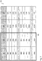
- the mapping system may include a relational database stored in figure 7 is shown schematically as table 700.
- the assignment system assigns the cop 91 an identification of a point in time when the cop 91 was wound up and an identification of that spinning position 21 on which it was produced. An identification of a point in time when the cop 91 is unwound can e.g. B.
- Doff number ie a natural number that uniquely identifies a setting (“Doff") of cops 91 produced at the same time from the ring spinning machine 2 and is increased by one for each subsequent Doff.
- the Doff numbers are in a first column 701 of the table. 700 listed.
- the spinning position 21 on which the cop 91 was produced can be identified by means of a spinning position number.
- the spinning position numbers are listed in a second column 702 of table 700.
- a Doff number and the associated spinning position number together uniquely identify a line in the table 700 so that they can be used as a so-called key in the database. this is in figure 7 indicated by a frame 705 around the two key columns 701, 702.
- the assignment system assigns an identification carrier to the cop 91 and also stores identification data of the identification carrier in the relational database.
- the allocation system can include a cop tracking system, which is known per se and does not need to be discussed in detail here. such as B. in the EP-3'305'953 A1 described, each cop 91 can be transported from the ring spinning machine 2 to the winding machine 3 on a bobbin plate that is provided with an RFID label. When leaving the ring spinning machine 2, the RFID label is written with identification data that uniquely identify the Doff number and the spinning position number.
- the identification data is listed in a third column 703 of the table 700, e.g. B. as natural numbers, each of which uniquely identifies a cop 91, at least during its feeding to the winding units 31.
- the associated spinning data are listed in a fourth column 704 of the table 700, for example the number of yarn breaks per hour.
- Table 700 should therefore be read as follows: During doffing 0001, there were 0.67 thread breaks per hour at spinning position 001L; the cop so produced is identified as "14377".
- the spinning monitoring control unit 43 determines the spinning data for the individual cops 91.
- the spinning data, the Doff number and the spinning position number are stored in a relational database (cf. figure 7 ) saved.
- the database can be located in the spinning monitoring unit 43, in the spinning expert system 45, in the evaluation device 6, in the yarn expert system 55, in the yarn monitoring control unit 53, in the feed control unit 33, in another computing unit or distributed over several of the units mentioned.
- Two classes of similar spinning data are specified, namely permissible spinning data for properly functioning spinning positions 21 and impermissible spinning data for insufficiently functioning spinning positions 21.
- Each cop 91 is classified into one of the two classes according to the spinning data assigned to it.
- cops 91 with two or fewer thread breaks per hour can be classified as permissible, so that z. B. the cop 91 with the Doff number 0001 from the spinning position 003L is not permitted.
- Each cop 91 is transported from the ring spinning machine 2 to the winding machine 3 on a bobbin plate which is provided with an RFID label.
- the RFID label is written with identification data, which can be clearly identified by means of the Doff number and the spinning position number.
- the identification data are also stored in the relational database (cf. figure 7 ) saved.
- the identification data are read from the RFID label.
- the corresponding spinning data are read from the database, with the doff number and the spinning position number being used as keys for identifying the spinning data. If the respective spinning data turns out to be impermissible, the feed control unit 33 feeds the relevant cop 91 classified as impermissible to the sorting station 35, otherwise to one of the winding units 31. All cops 91 classified as permissible are thus rewound on the winding machine 3, while all of them are classified as impermissible classified cops 91 are sorted out in the sorting station 35. This ensures that the yarn 92 wound onto the yarn spools 93 is of consistently good quality.
- the empty cop tubes are removed from the winding machine 3 and fed back to the ring spinning machine 2, which in figure 1 with dashed arrows 32 is indicated.
- FIG. 12 uses a flowchart to illustrate how decisions about feeding cops 91 are made in one embodiment of the method according to the invention.
- three classes of spinning data similar to each other are specified.
- Cops 91 belonging to a first class are to be rewound first.
- cops 91 belonging to a second or a third class are to be rewound at the same time, but in different groups of winding units 31.
- the spinning data of a cop 91 removed 201 from the ring spinning machine 2 are first examined 202 to determine whether they belong to the first class of spinning data. If so, the bobbin 91 is fed 211 to any of the winding units 31 at which there is a need for bobbins 91 at that moment. There the cop 91 is rewound 212 onto a yarn spool 93. When several first-class cops 91 have been rewound onto the yarn spool 93, so that the yarn spool 93 contains the prescribed quantity of yarn 92, then the yarn spool 93 is completed 213 and is removed from the Winding unit 31 removed 214. It contains only first-class yarn 92. If the yarn package 93 is not yet completed 213, another first-class cop 91 is fed 21I to the winding unit 31 in question.
- the cop 91 is initially fed 203 to the selection station 35. There it is temporarily stored until all first-class cops 91 have been rewound. After all first-class cops 91 have been rewound, a class change 204 takes place on the winding machine 3. The cops 91 temporarily stored in the selection station 35 are now transported again to the winding machine 3 (arrow 36). The spinning data of a cop 91 transported 205 in this way to the winding machine 3 are then examined 206 to determine whether they belong to the second class of spinning data. If so, the cop 91 is fed 221 to a winding unit 31 which belongs to a first group of winding units 31 .
- the cop 91 is rewound 222 onto a yarn spool 93.
- the yarn spool 93 contains the prescribed amount of yarn 92, the yarn spool 93 is completed 223 and is taken from the winding station 31 removed 224.
- the spinning data of a cop 91 transported 205 from the selection station 35 to the winding machine 3 do not belong 206 to the second class of spinning data, they belong to the third class.
- the cop 91 is fed to a winding unit 31 231 which belongs to a second group of winding units 31 .
- the cop 91 is rewound 232 onto a yarn spool 93, which after its completion 233 contains third-class yarn 234.
- the rewinding 222, 232 in the first and the second group of winding units 31 can take place simultaneously on the same winding machine 3 (cf. figure 5 ).
- the cops 91 can either be fed to a first winding machine, which only winds around second-class yarn 222, or to a second winding machine, which only winds around third-class yarn 232.
- FIGS Figures 3-5 illustrate such variants. Using schematic diagrams, they show how cops 91 (not shown) can be fed to the winding units 31 in three different embodiments of the method according to the invention.
- the diagrams of Figures 3-5 correspond to the lower right part of the figure 1 .
- Reference numerals 22, 34, 35 and 36 are used in FIGS Figures 3-5 with the same meaning as in figure 1 used; they were in the description of figure 1 explained so that they are not repeated here.
- FIG 3 The embodiment of figure 3 largely corresponds to that of figures 1 and 2 .
- a cop 91 is transported from the spinning station 21 to the winding machine 3 after it has been set down, which is indicated by the arrow 22 .
- the cop 91 is either fed to one of the winding stations 31 or to the sorting station 35.
- initially only first-class cops 91 are fed to the winding units 31 (arrows 34; figure 2 : reference numeral 211), while all others Cops 91 are temporarily stored in the selection station 35 ( figure 2 : reference numeral 203).
- a class change takes place ( figure 2 : reference numeral 204).
- the cops 91 temporarily stored in the selection station 35 are transported again to the winding machine 3, which is indicated by the arrow 36. Thereafter, the second-class cops 91 are fed to the winding units 31, etc. (in contrast to the embodiment of FIG figure 2 , in which the second-class and third-class cops 91 are rewound simultaneously).
- the non-first-class cops 91 which have not been fed to any of the winding units 31, are fed either to the first separating station 35.1, to a second separating station 35.2 or to a reject station 38.
- Second-class cops 91 are stored in the first sorting station 35.1, which, after the first-class cops 91 have been rewound, are again transported to the winding machine 3 (arrow 36.1) and rewound there.
- third-class cops 91 are stored, which, after the second-class cops 91 have been rewound, are transported to the winding machine 3 (arrow 36.2) and rewound there.
- sorting stations for third-class and higher-class cops can be provided.
- cops 91 are collected whose spinning data are so bad that they are not rewound.
- the scrap station 38 can be viewed as a special case of a reject station.
- a return 37 of the first-class cops 91 that have not been rewound can be provided.
- the flowchart of figure 6 illustrates part of an embodiment of the method according to the invention.
- the assumption here is that a spinning station 21, at which a cop 91 with impermissible spinning data has been wound up, is defective or faulty and will continue to produce cops 91 with impermissible spinning data in the future.
- the first question asked 602 is whether at least one spinning position 21 is already known and stored as a defective spinning position 21. If not, the spinning data of the cop 91 are checked 603 for their admissibility. If the spinning data are admissible, the cop 91 is fed 604 to one of the winding stations 31 and rewound there. Otherwise, the spinning position 21 at which the cop 91 was wound up is stored 606 as a defective spinning position 21 and the cop 91 is separated out as rejects 607.
- the question 605 is whether the cop 91 has been wound up at one of the known defective spinning positions 21. If so, the cop 91 can be discarded 607 as rejects without further examination of its spin data. This saves time and computational effort for an examination of the spin data. Only if the cop 91 has been wound up on a spinning position 21 that has previously functioned perfectly does its spinning data have to be checked for admissibility 603. If the spinning data prove to be impermissible, the spinning position 21 in question is saved as a defective spinning position 21 606 and the cop 91 set aside as a committee 607.
- a defective spinning position 21 it is desirable to repair a defective spinning position 21 as quickly as possible in order to achieve the desired quality of the yarn produced and high productivity of the ring spinning installation 1.
- a corresponding instruction can be issued to the operator.
- the central control and evaluation device can trigger an automatic repair of the defective spinning position 21.
Landscapes
- Engineering & Computer Science (AREA)
- Mechanical Engineering (AREA)
- Textile Engineering (AREA)
- Quality & Reliability (AREA)
- Spinning Or Twisting Of Yarns (AREA)
- Filamentary Materials, Packages, And Safety Devices Therefor (AREA)
- Replacing, Conveying, And Pick-Finding For Filamentary Materials (AREA)
Applications Claiming Priority (3)
| Application Number | Priority Date | Filing Date | Title |
|---|---|---|---|
| CH6752018 | 2018-05-28 | ||
| CH9642018 | 2018-08-07 | ||
| PCT/CH2019/000017 WO2019227242A1 (de) | 2018-05-28 | 2019-05-27 | Automatische ringspinnanlage und verfahren zu ihrem automatischen betrieb |
Publications (2)
| Publication Number | Publication Date |
|---|---|
| EP3802389A1 EP3802389A1 (de) | 2021-04-14 |
| EP3802389B1 true EP3802389B1 (de) | 2022-08-24 |
Family
ID=66676965
Family Applications (1)
| Application Number | Title | Priority Date | Filing Date |
|---|---|---|---|
| EP19727582.9A Active EP3802389B1 (de) | 2018-05-28 | 2019-05-27 | Automatische ringspinnanlage und verfahren zu ihrem automatischen betrieb |
Country Status (5)
| Country | Link |
|---|---|
| US (1) | US11459676B2 (enExample) |
| EP (1) | EP3802389B1 (enExample) |
| JP (1) | JP7328997B2 (enExample) |
| CN (1) | CN112203962B (enExample) |
| WO (1) | WO2019227242A1 (enExample) |
Families Citing this family (4)
| Publication number | Priority date | Publication date | Assignee | Title |
|---|---|---|---|---|
| DE102021129449A1 (de) * | 2021-11-11 | 2023-05-11 | Maschinenfabrik Rieter Ag | Verfahren, Hülsentransportvorrichtung sowie Textilmaschine |
| CN117141862B (zh) * | 2023-09-21 | 2026-03-03 | 浙江恒逸石化有限公司 | 丝锭包装系统及其控制方法、控制装置 |
| CN117246609B (zh) * | 2023-11-15 | 2024-01-30 | 浙江恒逸石化有限公司 | 丝锭打码方法、装置、电子设备和存储介质 |
| CN117830295B (zh) * | 2024-02-21 | 2024-07-16 | 广州搏辉特自动化设备有限公司 | 缠绕机自动调节缠绕参数的控制方法、系统、设备及介质 |
Citations (1)
| Publication number | Priority date | Publication date | Assignee | Title |
|---|---|---|---|---|
| EP0392278B1 (de) * | 1989-04-12 | 1993-12-15 | W. SCHLAFHORST AG & CO. | Verfahren und Vorrichtung zum Zuordnen qualitätsbezogener Daten auf mit Kopsen bestückten Spulenträgern in einem Maschinensystem |
Family Cites Families (27)
| Publication number | Priority date | Publication date | Assignee | Title |
|---|---|---|---|---|
| DE2815162C3 (de) | 1978-04-07 | 1981-09-17 | Agfa-Gevaert Ag, 5090 Leverkusen | Durchlauf-Entwicklungsmaschine |
| CH641217A5 (de) * | 1979-10-29 | 1984-02-15 | Zellweger Uster Ag | Verfahren und vorrichtung zum sortieren von spinnkoerpern auf spinnmaschinen. |
| JPS61178375A (ja) * | 1985-01-31 | 1986-08-11 | Murata Mach Ltd | 精紡機の管理システム |
| DE3712654A1 (de) * | 1987-04-14 | 1988-10-27 | Schlafhorst & Co W | Verfahren zum ueberwachen der qualitaet von produktionsstellen, garnen und spulen an einem maschinenverbund aus wenigstens einer ringspinnmaschine und wenigstens einem spulautomaten |
| JPH047269A (ja) * | 1990-04-24 | 1992-01-10 | Murata Mach Ltd | 紡績工場における品質管理システム |
| CH685202A5 (de) * | 1991-03-07 | 1995-04-28 | Rieter Ag Maschf | Verfahren zum Steuern einer vernetzten Spinnereianlage. |
| CH685125A5 (de) * | 1991-11-08 | 1995-03-31 | Rieter Ag Maschf | Spinnereianlage mit einem Prozessleitrechner. |
| DE4306095A1 (de) | 1992-03-04 | 1993-10-07 | Rieter Ag Maschf | Verfahren und Einrichtung zum Steuern einer vernetzten Anlage |
| DE4209203B4 (de) | 1992-03-21 | 2005-11-03 | Saurer Gmbh & Co. Kg | Spinn-/Spulmaschinenkombination mit einer Vorrichtung zum Überwachen des ordnungsgemäßen Arbeitens der einzelnen Spinnstellen |
| DE4209219B4 (de) * | 1992-03-21 | 2005-08-04 | Saurer Gmbh & Co. Kg | Spulmaschine mit einem geschlossenen Transportsystem für Spulentransportteller |
| CH687994A5 (de) * | 1993-07-14 | 1997-04-15 | Luwa Ag Zellweger | Vorrichtung zur Produktionssteigerung von Spinnereimaschinen. |
| DE19918780A1 (de) | 1998-11-02 | 2000-05-04 | Fritz Stahlecker | Verfahren zum Überprüfen der Haarigkeit von Garnen |
| WO2007012212A1 (de) * | 2005-07-27 | 2007-02-01 | Uster Technologies Ag | Textilmaschine mit garnüberwachung |
| DE102005049436A1 (de) * | 2005-10-15 | 2007-04-19 | Saurer Gmbh & Co. Kg | Verfahren zum Betreiben einer Textilmaschine |
| JP5354343B2 (ja) * | 2005-11-18 | 2013-11-27 | ウステル・テヒノロジーズ・アクチエンゲゼルシヤフト | ファンシーヤーンの特徴付け方法 |
| EP2217746A1 (de) * | 2007-12-13 | 2010-08-18 | Uster Technologies AG | Vorrichtung und verfahren zur überwachung einer mehrzahl von arbeitsstellen einer ringspinnmaschine |
| CH699219A1 (de) * | 2008-07-25 | 2010-01-29 | Uster Technologies Ag | Verfahren und Vorrichtung zur Garnreinigung. |
| JP2011020837A (ja) | 2009-07-17 | 2011-02-03 | Murata Machinery Ltd | 精紡ワインダの繊維機械管理システム及び精紡ワインダ |
| CN103270413A (zh) | 2010-10-19 | 2013-08-28 | 乌斯特技术股份公司 | 清纱器和用于清纱的方法 |
| JP2014514225A (ja) * | 2011-03-16 | 2014-06-19 | ウステル・テヒノロジーズ・アクチエンゲゼルシヤフト | 繊維供試品の特徴づけ |
| US8804452B2 (en) | 2012-07-31 | 2014-08-12 | Micron Technology, Inc. | Data interleaving module |
| US9444509B2 (en) | 2012-09-27 | 2016-09-13 | Intel Corporation | Non-blocking power management for on-package input/output architectures |
| DE102015004305A1 (de) * | 2015-04-01 | 2016-10-06 | Saurer Germany Gmbh & Co. Kg | Verfahren zum Betreiben eines Verbundsystems aus mindestens einer Ringspinnmaschine und mindestens einer Spulmaschine sowie Verbundsystem |
| JP2017002415A (ja) | 2015-06-05 | 2017-01-05 | 村田機械株式会社 | 糸巻取システム、精紡機、自動ワインダ、及び糸巻取方法 |
| JP2017053047A (ja) | 2015-09-08 | 2017-03-16 | 村田機械株式会社 | 糸巻取装置、それを備える自動ワインダ、それを備える繊維機械システム、及び給糸ボビン異常検出方法 |
| DE102016007779A1 (de) * | 2016-06-24 | 2017-12-28 | Saurer Germany Gmbh & Co. Kg | Verfahren zum Überwachen des ordnungsgemäßen Arbeitens der Spinnstellen einer Ringspinnmaschine |
| JP2018193198A (ja) * | 2017-05-19 | 2018-12-06 | 村田機械株式会社 | 生産力表示制御装置及び方法並びに自動ワインダ |
-
2019
- 2019-05-27 EP EP19727582.9A patent/EP3802389B1/de active Active
- 2019-05-27 WO PCT/CH2019/000017 patent/WO2019227242A1/de not_active Ceased
- 2019-05-27 JP JP2020566843A patent/JP7328997B2/ja active Active
- 2019-05-27 US US15/733,761 patent/US11459676B2/en active Active
- 2019-05-27 CN CN201980036579.8A patent/CN112203962B/zh active Active
Patent Citations (1)
| Publication number | Priority date | Publication date | Assignee | Title |
|---|---|---|---|---|
| EP0392278B1 (de) * | 1989-04-12 | 1993-12-15 | W. SCHLAFHORST AG & CO. | Verfahren und Vorrichtung zum Zuordnen qualitätsbezogener Daten auf mit Kopsen bestückten Spulenträgern in einem Maschinensystem |
Also Published As
| Publication number | Publication date |
|---|---|
| WO2019227242A1 (de) | 2019-12-05 |
| US20210164132A1 (en) | 2021-06-03 |
| CN112203962A (zh) | 2021-01-08 |
| US11459676B2 (en) | 2022-10-04 |
| CN112203962B (zh) | 2022-11-01 |
| EP3802389A1 (de) | 2021-04-14 |
| JP7328997B2 (ja) | 2023-08-17 |
| JP2021525838A (ja) | 2021-09-27 |
Similar Documents
| Publication | Publication Date | Title |
|---|---|---|
| EP3802927B1 (de) | Ringspinnanlage und verfahren zu ihrem betrieb | |
| EP3802389B1 (de) | Automatische ringspinnanlage und verfahren zu ihrem automatischen betrieb | |
| EP0410429B1 (de) | Verfahren und Vorrichtung zum Betrieb einer Spinnereilinie | |
| DE3712654A1 (de) | Verfahren zum ueberwachen der qualitaet von produktionsstellen, garnen und spulen an einem maschinenverbund aus wenigstens einer ringspinnmaschine und wenigstens einem spulautomaten | |
| EP3672895B1 (de) | Verfahren und vorrichtung zum texturieren eines synthetischen fadens | |
| DE102016007779A1 (de) | Verfahren zum Überwachen des ordnungsgemäßen Arbeitens der Spinnstellen einer Ringspinnmaschine | |
| DE102019116475A1 (de) | Optimierung des Betriebes einer Spinnmaschine | |
| DE4306095A1 (de) | Verfahren und Einrichtung zum Steuern einer vernetzten Anlage | |
| DE102004052669A1 (de) | Verfahren zur Überwachung einer Spinnanlage zur Herstellung synthetischer Fäden | |
| DE3635576C2 (de) | Verfahren und Anlage zum Vorgarnspulenwechsel | |
| DE102015004261A1 (de) | Verfahren zum Betreiben eines Verbundsystems aus mindestens einer Ringspinnmaschine und mindestens einer Spulmaschine sowie Verbundsystem | |
| EP0360287B1 (de) | Kopsvorbereitungsstation | |
| EP0528003A1 (de) | Verfahren und einrichtung zum steuern einer vernetzten anlage | |
| EP4026934B1 (de) | Verfahren zum ansetzen und ansetzvorrichtung | |
| EP3802390A1 (de) | Verfahren und vorrichtung zum schmelzspinnen und aufwickeln mehrerer fäden | |
| EP2830982A1 (de) | Verfahren zur garnüberwachung | |
| EP4155442A1 (de) | Maschinenverbund ringspinnmaschine/kreuzspulautomat | |
| DE102021002646A1 (de) | Verfahren zur Überwachung einer Vielzahl von Bearbeitungsstellen für synthetische Fäden | |
| DE4333809C2 (de) | Verfahren und Vorrichtung zum Überwachen der Qualität von Fadenspulen | |
| DE102014010961A1 (de) | Verfahren und Vorrichtung zur Herstellung von schmelzgesponnenen Fäden | |
| CH714693A2 (de) | Verfahren zum Betrieb einer Ringspinnanlage und Ringspinnanlage. | |
| EP0512442A1 (de) | Produktionsplanung und -steuerung für eine Spinnereianlage | |
| EP0501913A1 (de) | Verfahren zum Betrieb einer aus einer Kopsvorbereitungsstation, einem Umlaufpuffer und mehreren Spulstellen bestehenden Spulmaschine | |
| DE4141407A1 (de) | Verfahren zum wechseln von rohstoffgebinden | |
| DE102022004857A1 (de) | Verfahren zum Ermitteln der Spulenqualität einer Sammelspule |
Legal Events
| Date | Code | Title | Description |
|---|---|---|---|
| STAA | Information on the status of an ep patent application or granted ep patent |
Free format text: STATUS: UNKNOWN |
|
| STAA | Information on the status of an ep patent application or granted ep patent |
Free format text: STATUS: THE INTERNATIONAL PUBLICATION HAS BEEN MADE |
|
| PUAI | Public reference made under article 153(3) epc to a published international application that has entered the european phase |
Free format text: ORIGINAL CODE: 0009012 |
|
| STAA | Information on the status of an ep patent application or granted ep patent |
Free format text: STATUS: REQUEST FOR EXAMINATION WAS MADE |
|
| 17P | Request for examination filed |
Effective date: 20210111 |
|
| AK | Designated contracting states |
Kind code of ref document: A1 Designated state(s): AL AT BE BG CH CY CZ DE DK EE ES FI FR GB GR HR HU IE IS IT LI LT LU LV MC MK MT NL NO PL PT RO RS SE SI SK SM TR |
|
| AX | Request for extension of the european patent |
Extension state: BA ME |
|
| DAV | Request for validation of the european patent (deleted) | ||
| DAX | Request for extension of the european patent (deleted) | ||
| REG | Reference to a national code |
Ref country code: DE Ref legal event code: R079 Ref document number: 502019005416 Country of ref document: DE Free format text: PREVIOUS MAIN CLASS: B65H0063000000 Ipc: B65H0067060000 |
|
| GRAP | Despatch of communication of intention to grant a patent |
Free format text: ORIGINAL CODE: EPIDOSNIGR1 |
|
| STAA | Information on the status of an ep patent application or granted ep patent |
Free format text: STATUS: GRANT OF PATENT IS INTENDED |
|
| RIC1 | Information provided on ipc code assigned before grant |
Ipc: D01H 1/02 20060101ALI20220110BHEP Ipc: D01H 13/32 20060101ALI20220110BHEP Ipc: D01H 9/18 20060101ALI20220110BHEP Ipc: B65H 63/00 20060101ALI20220110BHEP Ipc: B65H 67/06 20060101AFI20220110BHEP |
|
| INTG | Intention to grant announced |
Effective date: 20220209 |
|
| GRAJ | Information related to disapproval of communication of intention to grant by the applicant or resumption of examination proceedings by the epo deleted |
Free format text: ORIGINAL CODE: EPIDOSDIGR1 |
|
| STAA | Information on the status of an ep patent application or granted ep patent |
Free format text: STATUS: REQUEST FOR EXAMINATION WAS MADE |
|
| GRAP | Despatch of communication of intention to grant a patent |
Free format text: ORIGINAL CODE: EPIDOSNIGR1 |
|
| STAA | Information on the status of an ep patent application or granted ep patent |
Free format text: STATUS: GRANT OF PATENT IS INTENDED |
|
| INTC | Intention to grant announced (deleted) | ||
| INTG | Intention to grant announced |
Effective date: 20220516 |
|
| GRAS | Grant fee paid |
Free format text: ORIGINAL CODE: EPIDOSNIGR3 |
|
| GRAA | (expected) grant |
Free format text: ORIGINAL CODE: 0009210 |
|
| STAA | Information on the status of an ep patent application or granted ep patent |
Free format text: STATUS: THE PATENT HAS BEEN GRANTED |
|
| AK | Designated contracting states |
Kind code of ref document: B1 Designated state(s): AL AT BE BG CH CY CZ DE DK EE ES FI FR GB GR HR HU IE IS IT LI LT LU LV MC MK MT NL NO PL PT RO RS SE SI SK SM TR |
|
| REG | Reference to a national code |
Ref country code: CH Ref legal event code: EP |
|
| REG | Reference to a national code |
Ref country code: DE Ref legal event code: R096 Ref document number: 502019005416 Country of ref document: DE |
|
| REG | Reference to a national code |
Ref country code: IE Ref legal event code: FG4D Free format text: LANGUAGE OF EP DOCUMENT: GERMAN |
|
| REG | Reference to a national code |
Ref country code: AT Ref legal event code: REF Ref document number: 1513538 Country of ref document: AT Kind code of ref document: T Effective date: 20220915 |
|
| REG | Reference to a national code |
Ref country code: LT Ref legal event code: MG9D |
|
| REG | Reference to a national code |
Ref country code: NL Ref legal event code: MP Effective date: 20220824 |
|
| PG25 | Lapsed in a contracting state [announced via postgrant information from national office to epo] |
Ref country code: SE Free format text: LAPSE BECAUSE OF FAILURE TO SUBMIT A TRANSLATION OF THE DESCRIPTION OR TO PAY THE FEE WITHIN THE PRESCRIBED TIME-LIMIT Effective date: 20220824 Ref country code: RS Free format text: LAPSE BECAUSE OF FAILURE TO SUBMIT A TRANSLATION OF THE DESCRIPTION OR TO PAY THE FEE WITHIN THE PRESCRIBED TIME-LIMIT Effective date: 20220824 Ref country code: PT Free format text: LAPSE BECAUSE OF FAILURE TO SUBMIT A TRANSLATION OF THE DESCRIPTION OR TO PAY THE FEE WITHIN THE PRESCRIBED TIME-LIMIT Effective date: 20221226 Ref country code: NO Free format text: LAPSE BECAUSE OF FAILURE TO SUBMIT A TRANSLATION OF THE DESCRIPTION OR TO PAY THE FEE WITHIN THE PRESCRIBED TIME-LIMIT Effective date: 20221124 Ref country code: NL Free format text: LAPSE BECAUSE OF FAILURE TO SUBMIT A TRANSLATION OF THE DESCRIPTION OR TO PAY THE FEE WITHIN THE PRESCRIBED TIME-LIMIT Effective date: 20220824 Ref country code: LV Free format text: LAPSE BECAUSE OF FAILURE TO SUBMIT A TRANSLATION OF THE DESCRIPTION OR TO PAY THE FEE WITHIN THE PRESCRIBED TIME-LIMIT Effective date: 20220824 Ref country code: LT Free format text: LAPSE BECAUSE OF FAILURE TO SUBMIT A TRANSLATION OF THE DESCRIPTION OR TO PAY THE FEE WITHIN THE PRESCRIBED TIME-LIMIT Effective date: 20220824 Ref country code: FI Free format text: LAPSE BECAUSE OF FAILURE TO SUBMIT A TRANSLATION OF THE DESCRIPTION OR TO PAY THE FEE WITHIN THE PRESCRIBED TIME-LIMIT Effective date: 20220824 |
|
| PG25 | Lapsed in a contracting state [announced via postgrant information from national office to epo] |
Ref country code: PL Free format text: LAPSE BECAUSE OF FAILURE TO SUBMIT A TRANSLATION OF THE DESCRIPTION OR TO PAY THE FEE WITHIN THE PRESCRIBED TIME-LIMIT Effective date: 20220824 Ref country code: IS Free format text: LAPSE BECAUSE OF FAILURE TO SUBMIT A TRANSLATION OF THE DESCRIPTION OR TO PAY THE FEE WITHIN THE PRESCRIBED TIME-LIMIT Effective date: 20221224 Ref country code: HR Free format text: LAPSE BECAUSE OF FAILURE TO SUBMIT A TRANSLATION OF THE DESCRIPTION OR TO PAY THE FEE WITHIN THE PRESCRIBED TIME-LIMIT Effective date: 20220824 Ref country code: GR Free format text: LAPSE BECAUSE OF FAILURE TO SUBMIT A TRANSLATION OF THE DESCRIPTION OR TO PAY THE FEE WITHIN THE PRESCRIBED TIME-LIMIT Effective date: 20221125 |
|
| PG25 | Lapsed in a contracting state [announced via postgrant information from national office to epo] |
Ref country code: SM Free format text: LAPSE BECAUSE OF FAILURE TO SUBMIT A TRANSLATION OF THE DESCRIPTION OR TO PAY THE FEE WITHIN THE PRESCRIBED TIME-LIMIT Effective date: 20220824 Ref country code: RO Free format text: LAPSE BECAUSE OF FAILURE TO SUBMIT A TRANSLATION OF THE DESCRIPTION OR TO PAY THE FEE WITHIN THE PRESCRIBED TIME-LIMIT Effective date: 20220824 Ref country code: ES Free format text: LAPSE BECAUSE OF FAILURE TO SUBMIT A TRANSLATION OF THE DESCRIPTION OR TO PAY THE FEE WITHIN THE PRESCRIBED TIME-LIMIT Effective date: 20220824 Ref country code: DK Free format text: LAPSE BECAUSE OF FAILURE TO SUBMIT A TRANSLATION OF THE DESCRIPTION OR TO PAY THE FEE WITHIN THE PRESCRIBED TIME-LIMIT Effective date: 20220824 Ref country code: CZ Free format text: LAPSE BECAUSE OF FAILURE TO SUBMIT A TRANSLATION OF THE DESCRIPTION OR TO PAY THE FEE WITHIN THE PRESCRIBED TIME-LIMIT Effective date: 20220824 |
|
| REG | Reference to a national code |
Ref country code: DE Ref legal event code: R097 Ref document number: 502019005416 Country of ref document: DE |
|
| PG25 | Lapsed in a contracting state [announced via postgrant information from national office to epo] |
Ref country code: SK Free format text: LAPSE BECAUSE OF FAILURE TO SUBMIT A TRANSLATION OF THE DESCRIPTION OR TO PAY THE FEE WITHIN THE PRESCRIBED TIME-LIMIT Effective date: 20220824 Ref country code: EE Free format text: LAPSE BECAUSE OF FAILURE TO SUBMIT A TRANSLATION OF THE DESCRIPTION OR TO PAY THE FEE WITHIN THE PRESCRIBED TIME-LIMIT Effective date: 20220824 |
|
| P01 | Opt-out of the competence of the unified patent court (upc) registered |
Effective date: 20230515 |
|
| PG25 | Lapsed in a contracting state [announced via postgrant information from national office to epo] |
Ref country code: AL Free format text: LAPSE BECAUSE OF FAILURE TO SUBMIT A TRANSLATION OF THE DESCRIPTION OR TO PAY THE FEE WITHIN THE PRESCRIBED TIME-LIMIT Effective date: 20220824 |
|
| PLBE | No opposition filed within time limit |
Free format text: ORIGINAL CODE: 0009261 |
|
| STAA | Information on the status of an ep patent application or granted ep patent |
Free format text: STATUS: NO OPPOSITION FILED WITHIN TIME LIMIT |
|
| 26N | No opposition filed |
Effective date: 20230525 |
|
| PG25 | Lapsed in a contracting state [announced via postgrant information from national office to epo] |
Ref country code: SI Free format text: LAPSE BECAUSE OF FAILURE TO SUBMIT A TRANSLATION OF THE DESCRIPTION OR TO PAY THE FEE WITHIN THE PRESCRIBED TIME-LIMIT Effective date: 20220824 |
|
| PG25 | Lapsed in a contracting state [announced via postgrant information from national office to epo] |
Ref country code: MC Free format text: LAPSE BECAUSE OF FAILURE TO SUBMIT A TRANSLATION OF THE DESCRIPTION OR TO PAY THE FEE WITHIN THE PRESCRIBED TIME-LIMIT Effective date: 20220824 |
|
| GBPC | Gb: european patent ceased through non-payment of renewal fee |
Effective date: 20230527 |
|
| REG | Reference to a national code |
Ref country code: BE Ref legal event code: MM Effective date: 20230531 |
|
| PG25 | Lapsed in a contracting state [announced via postgrant information from national office to epo] |
Ref country code: MC Free format text: LAPSE BECAUSE OF FAILURE TO SUBMIT A TRANSLATION OF THE DESCRIPTION OR TO PAY THE FEE WITHIN THE PRESCRIBED TIME-LIMIT Effective date: 20220824 Ref country code: LU Free format text: LAPSE BECAUSE OF NON-PAYMENT OF DUE FEES Effective date: 20230527 |
|
| REG | Reference to a national code |
Ref country code: IE Ref legal event code: MM4A |
|
| PG25 | Lapsed in a contracting state [announced via postgrant information from national office to epo] |
Ref country code: IE Free format text: LAPSE BECAUSE OF NON-PAYMENT OF DUE FEES Effective date: 20230527 |
|
| PG25 | Lapsed in a contracting state [announced via postgrant information from national office to epo] |
Ref country code: IE Free format text: LAPSE BECAUSE OF NON-PAYMENT OF DUE FEES Effective date: 20230527 Ref country code: GB Free format text: LAPSE BECAUSE OF NON-PAYMENT OF DUE FEES Effective date: 20230527 |
|
| PG25 | Lapsed in a contracting state [announced via postgrant information from national office to epo] |
Ref country code: FR Free format text: LAPSE BECAUSE OF NON-PAYMENT OF DUE FEES Effective date: 20230531 Ref country code: BE Free format text: LAPSE BECAUSE OF NON-PAYMENT OF DUE FEES Effective date: 20230531 |
|
| PG25 | Lapsed in a contracting state [announced via postgrant information from national office to epo] |
Ref country code: BG Free format text: LAPSE BECAUSE OF FAILURE TO SUBMIT A TRANSLATION OF THE DESCRIPTION OR TO PAY THE FEE WITHIN THE PRESCRIBED TIME-LIMIT Effective date: 20220824 |
|
| PG25 | Lapsed in a contracting state [announced via postgrant information from national office to epo] |
Ref country code: BG Free format text: LAPSE BECAUSE OF FAILURE TO SUBMIT A TRANSLATION OF THE DESCRIPTION OR TO PAY THE FEE WITHIN THE PRESCRIBED TIME-LIMIT Effective date: 20220824 |
|
| PGFP | Annual fee paid to national office [announced via postgrant information from national office to epo] |
Ref country code: DE Payment date: 20250521 Year of fee payment: 7 |
|
| PGFP | Annual fee paid to national office [announced via postgrant information from national office to epo] |
Ref country code: IT Payment date: 20250527 Year of fee payment: 7 |
|
| REG | Reference to a national code |
Ref country code: AT Ref legal event code: MM01 Ref document number: 1513538 Country of ref document: AT Kind code of ref document: T Effective date: 20240527 |
|
| PGFP | Annual fee paid to national office [announced via postgrant information from national office to epo] |
Ref country code: CH Payment date: 20250601 Year of fee payment: 7 |
|
| PG25 | Lapsed in a contracting state [announced via postgrant information from national office to epo] |
Ref country code: AT Free format text: LAPSE BECAUSE OF NON-PAYMENT OF DUE FEES Effective date: 20240527 |
|
| PG25 | Lapsed in a contracting state [announced via postgrant information from national office to epo] |
Ref country code: CY Free format text: LAPSE BECAUSE OF FAILURE TO SUBMIT A TRANSLATION OF THE DESCRIPTION OR TO PAY THE FEE WITHIN THE PRESCRIBED TIME-LIMIT; INVALID AB INITIO Effective date: 20190527 |
|
| PGFP | Annual fee paid to national office [announced via postgrant information from national office to epo] |
Ref country code: TR Payment date: 20250521 Year of fee payment: 7 |
|
| PG25 | Lapsed in a contracting state [announced via postgrant information from national office to epo] |
Ref country code: HU Free format text: LAPSE BECAUSE OF FAILURE TO SUBMIT A TRANSLATION OF THE DESCRIPTION OR TO PAY THE FEE WITHIN THE PRESCRIBED TIME-LIMIT; INVALID AB INITIO Effective date: 20190527 |
|
| PGFP | Annual fee paid to national office [announced via postgrant information from national office to epo] |
Ref country code: AT Payment date: 20260410 Year of fee payment: 5 |