EP3802389B1 - Automatic ring spinning system and method for automatically operating same - Google Patents
Automatic ring spinning system and method for automatically operating same Download PDFInfo
- Publication number
- EP3802389B1 EP3802389B1 EP19727582.9A EP19727582A EP3802389B1 EP 3802389 B1 EP3802389 B1 EP 3802389B1 EP 19727582 A EP19727582 A EP 19727582A EP 3802389 B1 EP3802389 B1 EP 3802389B1
- Authority
- EP
- European Patent Office
- Prior art keywords
- spinning
- cop
- identification
- winding
- data
- Prior art date
- Legal status (The legal status is an assumption and is not a legal conclusion. Google has not performed a legal analysis and makes no representation as to the accuracy of the status listed.)
- Active
Links
- 238000007378 ring spinning Methods 0.000 title claims description 71
- 238000000034 method Methods 0.000 title claims description 29
- 238000009987 spinning Methods 0.000 claims description 254
- 238000004804 winding Methods 0.000 claims description 144
- 238000012544 monitoring process Methods 0.000 claims description 46
- 238000009434 installation Methods 0.000 description 19
- 238000011156 evaluation Methods 0.000 description 10
- 241000196324 Embryophyta Species 0.000 description 9
- 230000002950 deficient Effects 0.000 description 9
- 238000004519 manufacturing process Methods 0.000 description 5
- 230000008569 process Effects 0.000 description 5
- 230000007547 defect Effects 0.000 description 3
- 238000000151 deposition Methods 0.000 description 3
- 238000010586 diagram Methods 0.000 description 3
- 238000005457 optimization Methods 0.000 description 3
- 239000004753 textile Substances 0.000 description 3
- 206010020112 Hirsutism Diseases 0.000 description 2
- 239000000969 carrier Substances 0.000 description 2
- 230000008859 change Effects 0.000 description 2
- 235000013351 cheese Nutrition 0.000 description 2
- 239000007795 chemical reaction product Substances 0.000 description 2
- 238000013507 mapping Methods 0.000 description 2
- 230000008439 repair process Effects 0.000 description 2
- 238000000926 separation method Methods 0.000 description 2
- 238000012360 testing method Methods 0.000 description 2
- 238000012546 transfer Methods 0.000 description 2
- 230000032258 transport Effects 0.000 description 2
- TVEXGJYMHHTVKP-UHFFFAOYSA-N 6-oxabicyclo[3.2.1]oct-3-en-7-one Chemical compound C1C2C(=O)OC1C=CC2 TVEXGJYMHHTVKP-UHFFFAOYSA-N 0.000 description 1
- 240000002129 Malva sylvestris Species 0.000 description 1
- 235000006770 Malva sylvestris Nutrition 0.000 description 1
- 230000005540 biological transmission Effects 0.000 description 1
- 239000003795 chemical substances by application Substances 0.000 description 1
- 238000005520 cutting process Methods 0.000 description 1
- 230000001419 dependent effect Effects 0.000 description 1
- 238000005516 engineering process Methods 0.000 description 1
- 238000012432 intermediate storage Methods 0.000 description 1
- 238000009940 knitting Methods 0.000 description 1
- 238000005259 measurement Methods 0.000 description 1
- 238000012806 monitoring device Methods 0.000 description 1
- 238000012545 processing Methods 0.000 description 1
- 238000005204 segregation Methods 0.000 description 1
- 238000009941 weaving Methods 0.000 description 1
Images


Classifications
-
- B—PERFORMING OPERATIONS; TRANSPORTING
- B65—CONVEYING; PACKING; STORING; HANDLING THIN OR FILAMENTARY MATERIAL
- B65H—HANDLING THIN OR FILAMENTARY MATERIAL, e.g. SHEETS, WEBS, CABLES
- B65H63/00—Warning or safety devices, e.g. automatic fault detectors, stop-motions ; Quality control of the package
- B65H63/006—Warning or safety devices, e.g. automatic fault detectors, stop-motions ; Quality control of the package quality control of the package
-
- B—PERFORMING OPERATIONS; TRANSPORTING
- B65—CONVEYING; PACKING; STORING; HANDLING THIN OR FILAMENTARY MATERIAL
- B65H—HANDLING THIN OR FILAMENTARY MATERIAL, e.g. SHEETS, WEBS, CABLES
- B65H67/00—Replacing or removing cores, receptacles, or completed packages at paying-out, winding, or depositing stations
- B65H67/06—Supplying cores, receptacles, or packages to, or transporting from, winding or depositing stations
- B65H67/063—Marking or identifying devices for packages
-
- D—TEXTILES; PAPER
- D01—NATURAL OR MAN-MADE THREADS OR FIBRES; SPINNING
- D01H—SPINNING OR TWISTING
- D01H1/00—Spinning or twisting machines in which the product is wound-up continuously
- D01H1/02—Spinning or twisting machines in which the product is wound-up continuously ring type
-
- D—TEXTILES; PAPER
- D01—NATURAL OR MAN-MADE THREADS OR FIBRES; SPINNING
- D01H—SPINNING OR TWISTING
- D01H13/00—Other common constructional features, details or accessories
- D01H13/32—Counting, measuring, recording or registering devices
-
- D—TEXTILES; PAPER
- D01—NATURAL OR MAN-MADE THREADS OR FIBRES; SPINNING
- D01H—SPINNING OR TWISTING
- D01H9/00—Arrangements for replacing or removing bobbins, cores, receptacles, or completed packages at paying-out or take-up stations ; Combination of spinning-winding machine
- D01H9/18—Arrangements for replacing or removing bobbins, cores, receptacles, or completed packages at paying-out or take-up stations ; Combination of spinning-winding machine for supplying bobbins, cores, receptacles, or completed packages to, or transporting from, paying-out or take-up stations ; Arrangements to prevent unwinding of roving from roving bobbins
-
- B—PERFORMING OPERATIONS; TRANSPORTING
- B65—CONVEYING; PACKING; STORING; HANDLING THIN OR FILAMENTARY MATERIAL
- B65H—HANDLING THIN OR FILAMENTARY MATERIAL, e.g. SHEETS, WEBS, CABLES
- B65H2701/00—Handled material; Storage means
- B65H2701/30—Handled filamentary material
- B65H2701/31—Textiles threads or artificial strands of filaments
Definitions
- the present invention is in the field of ring spinning. It relates to an automatic ring spinning installation and a method for its automatic operation, according to the independent patent claims.
- a ring spinning installation usually includes a ring spinning machine and a winding machine.
- the ring spinning machine has a large number of spinning positions. At each spinning position, roving is pulled off a roving spool, stretched, twisted (spun) and wound onto a cop (yarn spool) as yarn.
- Systems for monitoring the operation of the spinning positions e.g. B. for detecting thread breaks or "creeping spindles" (ie spindles that work at a speed below the set machine speed) are known.
- Such spinning monitoring systems typically measure the rotational speed of the respective ring traveler (e.g. US-4,222,657 A ) or the yarn (e.g. WO-2014/022189 A1 ).
- the USTER ® SENTINEL ring spinning optimization system which is described in the brochure "USTER ® SENTINEL - The ring spinning optimization system", Uster Technologies AG, 2016, belongs to the first category.
- the USTER ® SENTINEL ring spinning optimization system creates a bobbin build-up report in which, among other things, the average number of yarn breaks and the average rotational speed are graphically displayed as a function of the position along a longitudinal axis of a bobbin.
- the cop build report is output to an operator on a screen.
- the bobbins are transported from the ring spinning machine to a winding machine.
- Cop tracking systems are known which make it possible to assign a cop in the winding machine to the spinning position on which it was produced. The assignment can be made, for example, by means of an identification carrier on the cop tube (e.g. US-4,660,370 A ) or on a bobbin plate (caddy) that transports the bobbin (e.g. DE-42'09'203 A1 ), take place.
- the winding machine has a large number of winding positions. At each winding position, several bobbins are rewound onto a cross-wound bobbin one after the other.
- the purpose of rewinding is to produce large spools of yarn that can be transported and used efficiently.
- the properties of the yarn are monitored and compared with specified quality criteria. If the quality criteria are not met, the faulty area can be removed from the yarn.
- So-called yarn clearing systems are known for this purpose, e.g. B. from the WO-2012/051730 A1 .
- DE-43'06'095 A1 discloses a method and a device for controlling a networked spinning plant.
- the spinning plant comprises a ring spinning machine, an automatic operating system assigned to the ring spinning machine and a winding machine linked to the ring spinning machine with a yarn clearer. It is equipped with a cop tracking system. Information is exchanged to optimize the spinning plant.
- the operating machine not only carries out operating operations, but also collects information on the status of the spinning positions and yarn breakages in the individual bobbins.
- the winding machine or its yarn clearer can determine via the bobbin tracking system that a specific spindle of the ring spinning machine is always producing bad yarn.
- EP-3'305'953 A1 discloses a yarn winding system with a spinning machine and an automatic winding machine.
- the spinning machine is provided with a monitoring device for generating spinning information and a transmission unit for sending the spinning information to the winding machine.
- the winder is provided with a receiving unit for receiving the spinning information and a controller for controlling the operation of the winder based on the spinning information received by the receiving unit.
- DE-10'2015'004'305 A1 relates to a method for operating an interconnected system comprising at least one ring spinning machine and at least one winding machine.
- the total thread length wound onto the cops is determined, and the cops are fed to the winding units as a function of the total thread length determined.
- Yarn breaks on the bobbins can be taken into account when distributing the bobbins to the winding positions in order to distribute splices evenly on the cheeses.
- the DE-199'18'780 A1 suggests connecting the ring spinning machine to a test station.
- the yarns are automatically checked for hairiness and the bobbins are automatically sorted depending on the test result.
- only bobbins with yarns without differences in hairiness are used.
- the EP-0'392'278 A1 pass the bobbins on bobbin carriers a converter that connects at least one ring spinning machine and at least one winding machine.
- the bobbin carriers equipped with bobbins are assigned data relating to different yarn qualities.
- Mixed bobbins with different qualities are coded and passed to the appropriate areas of the winding machine after the transfer unit.
- the invention is based on the idea of determining values of a parameter characteristic of the operation of the spinning position during spinning, in particular during the winding of the cop, automatically assigning them to the cop and taking them into account in an automatic decision about feeding the cop to one of the winding positions .
- the automatic assignment takes place on the basis of an identification of a point in time when the cop was wound up and an identification of the spinning station at which the cop was wound up.
- Bobbins that encountered problems during manufacture or winding can thus be discarded before rewinding. They can be discarded as scrap or rewound into inferior quality yarn spools.
- the method according to the invention is used for the automatic operation of a ring spinning installation which contains a ring spinning machine with a large number of spinning positions for spinning yarn and a winding machine with a large number of winding positions for rewinding the yarn.
- Yarn is spun at one of the spinning positions and wound up into a cop.
- values of a parameter characteristic of the operation of the spinning position are determined during the winding of the cop and stored as spinning data.
- the spinning data are assigned to the cop.
- the bobbin is set down from the spinning position.
- the spinning data assigned to the cop are taken into account in an automatic decision about feeding the cop to one of the winding stations after it has been set down.
- the parameter included in the spinning data that is characteristic of the operation of the spinning position includes a ring traveler speed.
- An identification of the point in time at which the cop was wound up and an identification of the spinning position are automatically assigned to the cop.
- the spinning data are automatically assigned to the bobbin based on the identification of the time at which the bobbin was wound up and the identification of the spinning position.
- the spinning data, the identification of the time at which the cop was wound up and the identification of the spinning position are stored in a relational database.
- the identification of the point in time at which the bobbin was wound up and the identification of the spinning position are used in the relational database as a key for identifying the spinning data to be assigned to the bobbin.
- An identification carrier can be assigned to the cop, identification data of the identification carrier can be stored in the relational database and the identification of the time of the Winding of the cop and the identification of the spinning position in the relational database can be used as a key for identifying both the spinning data to be assigned to the cop and the identification data of the identification carrier.
- the decision about feeding a first cop is adopted for several subsequent cops, which after the first cop were wound up at the same spinning position as the first cop, without taking their spinning data into account.
- the cop is sorted out after it has been set down and is not fed to any of the winding units, at least during a waiting period.
- At least two classes of spinning data that are similar to one another are formed.
- the decision is made for each of the at least two classes and a result of the decision is assigned to the respective class.
- the bobbin is classified into one of at least two classes according to the stored spinning data.
- the cop is dealt with according to the result assigned to the relevant class.
- the yarn is rewound from the cop onto a yarn package, and cops classified in the same class are sequentially fed to one of the winding stations so that the yarn wound on these cops is rewound onto a single yarn package.
- the cops classified in the same class can be temporarily stored after being set down before they are fed to the winding unit.
- the parameter which is characteristic of the operation of the spinning position and which is comprised by the spinning data is additionally selected from the following set: number of thread breaks per unit of time, air temperature, air humidity.
- the automatic ring spinning installation includes a ring spinning machine with a large number of spinning stations for spinning yarn and for winding the yarn onto a cop in each case. It also includes a spinning monitoring system for monitoring the operation of the spinning positions, with a spinning sensor at each of the spinning positions for measuring a spinning variable and a spinning monitoring control unit connected to the spinning sensor, which is set up to receive values of the spinning variable from the spinning sensor of a spinning position during the winding of a cop , from which values of a parameter characteristic of the operation of the spinning position are determined and stored as spinning data.
- the ring spinning plant includes a depositing device for depositing the bobbins from the spinning positions.
- the ring spinning installation contains a feed system, controlled by a feed control unit, for feeding the cops deposited by the depositing device to the winding stations and an allocation system for allocating the spinning data to the associated cop.
- the feed control unit is connected to the spinning monitoring control unit and set up to make a decision about feeding a respective cop to one of the winding positions, taking into account the spinning data assigned to the cop by the allocation system.
- the spinning monitoring control unit is set up to determine values of a ring traveler speed as a parameter that is characteristic of the operation of the spinning position and to store it as spinning data.
- the assignment system is set up to assign an identification of a point in time at which the cop was wound up and an identification of the spinning position on which the cop was wound up to the cop and to assign the spinning data to the cop on the basis of the identification of the point in time at which the cop was wound up and the identification of the spinning position .
- the mapping system includes a relational database.
- the relational database is set up to store the spinning data, the identification of the time at which the cop is wound up and the identification of the spinning position, and to use the identification of the time at which the cop is wound up and the identification of the spinning position as a key for identifying the spinning data to be assigned to the cop .
- the assignment system can be set up to assign an identification carrier to the cop, identification data of the identification carrier in to store the relational database and to use the identification of the time of winding the bobbin and the identification of the spinning position in the relational database as a key for identifying both the spinning data to be assigned to the bobbin and the identification data of the identification carrier.
- the assignment system is preferably set up to take over the decision about feeding a first cop for a plurality of subsequent cops which, after the first cop, were wound up at the same spinning position as the first cop, without taking their spinning data into account.
- the ring spinning installation additionally includes a sorting station for accommodating those cops that are sorted out by the feed control unit and are not fed to any of the winding stations, at least during a waiting period.
- the spinning monitoring control unit is set up to additionally determine values of the parameter characteristic of the operation of the spinning position from the following set and store them as spinning data: number of thread breaks per unit of time, air temperature, humidity.
- cops which have encountered problems during manufacture or winding can be discarded. This saves cuts by yarn clearers on the winding machine, which increases the efficiency of the winding machine and ultimately the overall productivity of the automatic ring spinning system.
- the invention also reduces the risk of yarn defects getting onto the yarn package. It thus increases the quality of the yarn bobbins produced by the automatic ring spinning system.
- the invention also offers the possibility of specifically producing bobbins of several different quality classes, with the bobbins having a homogeneous quality level within a quality class. Depending on the quality class, the yarn bobbins can be sold at different prices for different further uses, which increases the profitability of the ring spinning plant.
- FIG 1 shows schematically an automatic ring spinning installation 1 according to the invention.
- the ring spinning installation includes a ring spinning machine 2 and a winding machine 3.
- the ring spinning machine 2 has a large number of spinning stations 21 . Yarn is spun from roving at each spinning position 21 by means of the known ring spinning process and wound up to form what is known as a cop 91 .
- the ring spinning machine 2 is equipped with a spinning monitoring system 4 for monitoring the operation of the spinning positions 21, e.g. B. for detecting thread breaks or "creeping spindles".
- the spinning monitoring system 4 contains a spinning sensor 41 at each of the spinning stations 21.
- the spinning sensor 41 measures a spinning variable.
- Each spinning sensor 41 is connected to a spinning monitoring control unit 43 via a wired or wireless first data line 42 .
- the spinning sensor 41 sends values of the spinning measurement variable to the spinning monitoring control unit 43 via the first data line 42.
- the spinning monitoring control unit 43 receives the values. She determines from this for at least two different times during the winding of the cop 91 values of a parameter characteristic of the operation of the spinning position 21 and stores the determined values as spinning data.
- the parameter characteristic of the operation of the spinning station 21 includes a ring traveler speed. Examples of other parameters that are characteristic of the operation of the spinning position 21 are a number of thread breaks per unit of time, an air temperature and an air humidity.
- the full cops 91 produced at the same time are simultaneously deposited ("doffed") by the ring spinning machine 2;
- the ring spinning installation 1 is equipped with a settling device, which, however, is not shown in the drawings for the sake of simplicity.
- the cops 91 are transported to the winding machine 3, which in figure 1 with dashed arrows 22 is indicated.
- the winding machine 3 has a large number of winding stations 31 .
- yarn 92 is successively wound from a plurality of cops 91 onto a yarn package 93, e.g. B. a cheese, rewound.
- the winding machine 3 can be equipped with a yarn monitoring system 5 for monitoring properties of the yarn 92.
- the yarn monitoring system 5 contains a yarn sensor 51 at each of the winding positions, which is connected to a yarn monitoring control unit 53 via a wired or wireless second data line 52 .
- the yarn monitoring system 5 can e.g. B. be designed as a yarn cleaner system, wherein each yarn sensor 51 can be assigned a yarn cutting unit that removes impermissible yarn defects from the yarn 92.
- a cop 91 is automatically fed to one of the winding units 31 after it has been set down by the ring spinning machine 2, which in figure 1 with dashed arrows 34 is indicated.
- the cops 91 are fed to the winding units 31 by an automatic feed system which is controlled by a feed control unit 33 .
- the feed control unit 33 can be an independent unit or can be combined with a control unit of the winding machine 3 .
- the feeding control unit 33 is connected to the spinning monitor control unit 43 .
- the connection can be made via a wired or wireless third data line 62 .
- the ring spinning installation 1 contains a central control and evaluation device 6.
- the central control and evaluation device 6 is connected to the spinning monitoring control unit 43 and to the yarn monitoring control unit 53 via the third data line 62.
- the central control and evaluation device 6 receives data from the spinning monitoring control unit 43 and/or processes it from the yarn monitoring control unit 53, controls the ring spinning installation 1 or parts thereof and/or outputs information to an operator.
- it is preferably connected to an input unit and/or an output unit, via which the operator can make inputs or receive outputs.
- a mobile device 61 e.g. B. a mobile phone that communicates wirelessly with the central control and evaluation device 6, drawn as an input and output unit.
- other input units known per se such as e.g. B. a computer keyboard and output devices such. B. a computer screen can be used.
- the ring spinning installation 1 contains a plurality of spinning monitoring systems 4 on one or more ring spinning machines 2 whose spinning monitoring control units 43 are connected to a spinning expert system 45 .
- the spinning expert system 45 is set up to receive data from the spinning monitoring control units 43 , to process them and to output them in a suitable form, and to control the spinning monitoring control units 43 . It is in turn connected to the central control and evaluation device 6 .
- the ring spinning installation 1 contains a plurality of yarn monitoring systems 5 on one or more winding machines 3 whose yarn monitoring control units 53 are connected to a yarn expert system 55 .
- the yarn expert system 55 is set up to receive data from the yarn monitoring control units 53 , to process them and to output them in a suitable form, as well as to control the yarn monitoring control units 53 . It is in turn connected to the central control and evaluation device 6 .
- the ring spinning installation 1 contains an allocation system (not shown as an independent unit) for allocating the spinning data to the associated cop 91. Based on the figure 7 one possibility of assignment will now be described.
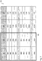
- the mapping system may include a relational database stored in figure 7 is shown schematically as table 700.
- the assignment system assigns the cop 91 an identification of a point in time when the cop 91 was wound up and an identification of that spinning position 21 on which it was produced. An identification of a point in time when the cop 91 is unwound can e.g. B.
- Doff number ie a natural number that uniquely identifies a setting (“Doff") of cops 91 produced at the same time from the ring spinning machine 2 and is increased by one for each subsequent Doff.
- the Doff numbers are in a first column 701 of the table. 700 listed.
- the spinning position 21 on which the cop 91 was produced can be identified by means of a spinning position number.
- the spinning position numbers are listed in a second column 702 of table 700.
- a Doff number and the associated spinning position number together uniquely identify a line in the table 700 so that they can be used as a so-called key in the database. this is in figure 7 indicated by a frame 705 around the two key columns 701, 702.
- the assignment system assigns an identification carrier to the cop 91 and also stores identification data of the identification carrier in the relational database.
- the allocation system can include a cop tracking system, which is known per se and does not need to be discussed in detail here. such as B. in the EP-3'305'953 A1 described, each cop 91 can be transported from the ring spinning machine 2 to the winding machine 3 on a bobbin plate that is provided with an RFID label. When leaving the ring spinning machine 2, the RFID label is written with identification data that uniquely identify the Doff number and the spinning position number.
- the identification data is listed in a third column 703 of the table 700, e.g. B. as natural numbers, each of which uniquely identifies a cop 91, at least during its feeding to the winding units 31.
- the associated spinning data are listed in a fourth column 704 of the table 700, for example the number of yarn breaks per hour.
- Table 700 should therefore be read as follows: During doffing 0001, there were 0.67 thread breaks per hour at spinning position 001L; the cop so produced is identified as "14377".
- the spinning monitoring control unit 43 determines the spinning data for the individual cops 91.
- the spinning data, the Doff number and the spinning position number are stored in a relational database (cf. figure 7 ) saved.
- the database can be located in the spinning monitoring unit 43, in the spinning expert system 45, in the evaluation device 6, in the yarn expert system 55, in the yarn monitoring control unit 53, in the feed control unit 33, in another computing unit or distributed over several of the units mentioned.
- Two classes of similar spinning data are specified, namely permissible spinning data for properly functioning spinning positions 21 and impermissible spinning data for insufficiently functioning spinning positions 21.
- Each cop 91 is classified into one of the two classes according to the spinning data assigned to it.
- cops 91 with two or fewer thread breaks per hour can be classified as permissible, so that z. B. the cop 91 with the Doff number 0001 from the spinning position 003L is not permitted.
- Each cop 91 is transported from the ring spinning machine 2 to the winding machine 3 on a bobbin plate which is provided with an RFID label.
- the RFID label is written with identification data, which can be clearly identified by means of the Doff number and the spinning position number.
- the identification data are also stored in the relational database (cf. figure 7 ) saved.
- the identification data are read from the RFID label.
- the corresponding spinning data are read from the database, with the doff number and the spinning position number being used as keys for identifying the spinning data. If the respective spinning data turns out to be impermissible, the feed control unit 33 feeds the relevant cop 91 classified as impermissible to the sorting station 35, otherwise to one of the winding units 31. All cops 91 classified as permissible are thus rewound on the winding machine 3, while all of them are classified as impermissible classified cops 91 are sorted out in the sorting station 35. This ensures that the yarn 92 wound onto the yarn spools 93 is of consistently good quality.
- the empty cop tubes are removed from the winding machine 3 and fed back to the ring spinning machine 2, which in figure 1 with dashed arrows 32 is indicated.
- FIG. 12 uses a flowchart to illustrate how decisions about feeding cops 91 are made in one embodiment of the method according to the invention.
- three classes of spinning data similar to each other are specified.
- Cops 91 belonging to a first class are to be rewound first.
- cops 91 belonging to a second or a third class are to be rewound at the same time, but in different groups of winding units 31.
- the spinning data of a cop 91 removed 201 from the ring spinning machine 2 are first examined 202 to determine whether they belong to the first class of spinning data. If so, the bobbin 91 is fed 211 to any of the winding units 31 at which there is a need for bobbins 91 at that moment. There the cop 91 is rewound 212 onto a yarn spool 93. When several first-class cops 91 have been rewound onto the yarn spool 93, so that the yarn spool 93 contains the prescribed quantity of yarn 92, then the yarn spool 93 is completed 213 and is removed from the Winding unit 31 removed 214. It contains only first-class yarn 92. If the yarn package 93 is not yet completed 213, another first-class cop 91 is fed 21I to the winding unit 31 in question.
- the cop 91 is initially fed 203 to the selection station 35. There it is temporarily stored until all first-class cops 91 have been rewound. After all first-class cops 91 have been rewound, a class change 204 takes place on the winding machine 3. The cops 91 temporarily stored in the selection station 35 are now transported again to the winding machine 3 (arrow 36). The spinning data of a cop 91 transported 205 in this way to the winding machine 3 are then examined 206 to determine whether they belong to the second class of spinning data. If so, the cop 91 is fed 221 to a winding unit 31 which belongs to a first group of winding units 31 .
- the cop 91 is rewound 222 onto a yarn spool 93.
- the yarn spool 93 contains the prescribed amount of yarn 92, the yarn spool 93 is completed 223 and is taken from the winding station 31 removed 224.
- the spinning data of a cop 91 transported 205 from the selection station 35 to the winding machine 3 do not belong 206 to the second class of spinning data, they belong to the third class.
- the cop 91 is fed to a winding unit 31 231 which belongs to a second group of winding units 31 .
- the cop 91 is rewound 232 onto a yarn spool 93, which after its completion 233 contains third-class yarn 234.
- the rewinding 222, 232 in the first and the second group of winding units 31 can take place simultaneously on the same winding machine 3 (cf. figure 5 ).
- the cops 91 can either be fed to a first winding machine, which only winds around second-class yarn 222, or to a second winding machine, which only winds around third-class yarn 232.
- FIGS Figures 3-5 illustrate such variants. Using schematic diagrams, they show how cops 91 (not shown) can be fed to the winding units 31 in three different embodiments of the method according to the invention.
- the diagrams of Figures 3-5 correspond to the lower right part of the figure 1 .
- Reference numerals 22, 34, 35 and 36 are used in FIGS Figures 3-5 with the same meaning as in figure 1 used; they were in the description of figure 1 explained so that they are not repeated here.
- FIG 3 The embodiment of figure 3 largely corresponds to that of figures 1 and 2 .
- a cop 91 is transported from the spinning station 21 to the winding machine 3 after it has been set down, which is indicated by the arrow 22 .
- the cop 91 is either fed to one of the winding stations 31 or to the sorting station 35.
- initially only first-class cops 91 are fed to the winding units 31 (arrows 34; figure 2 : reference numeral 211), while all others Cops 91 are temporarily stored in the selection station 35 ( figure 2 : reference numeral 203).
- a class change takes place ( figure 2 : reference numeral 204).
- the cops 91 temporarily stored in the selection station 35 are transported again to the winding machine 3, which is indicated by the arrow 36. Thereafter, the second-class cops 91 are fed to the winding units 31, etc. (in contrast to the embodiment of FIG figure 2 , in which the second-class and third-class cops 91 are rewound simultaneously).
- the non-first-class cops 91 which have not been fed to any of the winding units 31, are fed either to the first separating station 35.1, to a second separating station 35.2 or to a reject station 38.
- Second-class cops 91 are stored in the first sorting station 35.1, which, after the first-class cops 91 have been rewound, are again transported to the winding machine 3 (arrow 36.1) and rewound there.
- third-class cops 91 are stored, which, after the second-class cops 91 have been rewound, are transported to the winding machine 3 (arrow 36.2) and rewound there.
- sorting stations for third-class and higher-class cops can be provided.
- cops 91 are collected whose spinning data are so bad that they are not rewound.
- the scrap station 38 can be viewed as a special case of a reject station.
- a return 37 of the first-class cops 91 that have not been rewound can be provided.
- the flowchart of figure 6 illustrates part of an embodiment of the method according to the invention.
- the assumption here is that a spinning station 21, at which a cop 91 with impermissible spinning data has been wound up, is defective or faulty and will continue to produce cops 91 with impermissible spinning data in the future.
- the first question asked 602 is whether at least one spinning position 21 is already known and stored as a defective spinning position 21. If not, the spinning data of the cop 91 are checked 603 for their admissibility. If the spinning data are admissible, the cop 91 is fed 604 to one of the winding stations 31 and rewound there. Otherwise, the spinning position 21 at which the cop 91 was wound up is stored 606 as a defective spinning position 21 and the cop 91 is separated out as rejects 607.
- the question 605 is whether the cop 91 has been wound up at one of the known defective spinning positions 21. If so, the cop 91 can be discarded 607 as rejects without further examination of its spin data. This saves time and computational effort for an examination of the spin data. Only if the cop 91 has been wound up on a spinning position 21 that has previously functioned perfectly does its spinning data have to be checked for admissibility 603. If the spinning data prove to be impermissible, the spinning position 21 in question is saved as a defective spinning position 21 606 and the cop 91 set aside as a committee 607.
- a defective spinning position 21 it is desirable to repair a defective spinning position 21 as quickly as possible in order to achieve the desired quality of the yarn produced and high productivity of the ring spinning installation 1.
- a corresponding instruction can be issued to the operator.
- the central control and evaluation device can trigger an automatic repair of the defective spinning position 21.
Landscapes
- Engineering & Computer Science (AREA)
- Mechanical Engineering (AREA)
- Textile Engineering (AREA)
- Quality & Reliability (AREA)
- Spinning Or Twisting Of Yarns (AREA)
- Filamentary Materials, Packages, And Safety Devices Therefor (AREA)
- Replacing, Conveying, And Pick-Finding For Filamentary Materials (AREA)
Description
Die vorliegende Erfindung liegt auf dem Gebiet des Ringspinnens. Sie betrifft eine automatische Ringspinnanlage und ein Verfahren zu ihrem automatischen Betrieb, gemäss den unabhängigen Patentansprüchen.The present invention is in the field of ring spinning. It relates to an automatic ring spinning installation and a method for its automatic operation, according to the independent patent claims.
Eine Ringspinnanlage beinhaltet üblicherweise eine Ringspinnmaschine und eine Spulmaschine.A ring spinning installation usually includes a ring spinning machine and a winding machine.
Die Ringspinnmaschine weist eine Vielzahl von Spinnstellen auf. An jeder Spinnstelle wird Vorgarn von einer Vorgarnspule abgezogen, verstreckt, verdreht (versponnen) und als Garn auf einen Kops (Garnspule) aufgewickelt. Systeme zur Überwachung des Betriebs der Spinnstellen, z. B. zum Erkennen von Fadenbrüchen oder "Schleicherspindeln" (d. h. Spindeln, die mit einer Eigendrehzahl unterhalb der eingestellten Maschinendrehzahl arbeiten), sind bekannt. Solche Spinnüberwachungssysteme messen typischerweise die Rotationsgeschwindigkeit des jeweiligen Ringläufers (z. B.
Die Kopse werden nach ihrer Herstellung von der Ringspinnmaschine zu einer Spulmaschine transportiert. Es sind Kopsverfolgungssysteme bekannt, die es ermöglichen, einem in der Spulmaschine befindlichen Kops diejenige Spinnstelle zuzuordnen, auf der er hergestellt wurde. Die Zuordnung kann bspw. mittels eines Identifikationsträgers auf der Kopshülse (z. B.
Die Spulmaschine weist eine Vielzahl von Spulstellen auf. An jeder Spulstelle werden mehrere Kopse nacheinander auf eine Kreuzspule umgespult. Das Umspulen hat den Zweck, grosse Garnspulen herzustellen, die effizient transportiert und verwendet werden können. Während des Umspulens werden Eigenschaften des Garns überwacht und mit vorgegebenen Qualitätskriterien verglichen. Bei Nichterfüllen der Qualitätskriterien kann die fehlerhafte Stelle aus dem Garn entfernt werden. Zu diesem Zweck sind so genannte Garnreinigersysteme bekannt, z. B. aus der
Die DE-43'06'095 A1 offenbart ein Verfahren und eine Einrichtung zum Steuern einer vernetzten Spinnereianlage. Die Spinnereianlage umfasst eine Ringspinnmaschine, einen der Ringspinnmaschine zugeordneten Bedienungsautomaten und eine mit der Ringspinnmaschine verkettete Spulmaschine mit einem Garnreiniger. Sie ist mit einem Kopsverfolgungssystem ausgestattet. Zur Optimierung der Spinnereianlage werden Informationen ausgetauscht. Der Bedienungsautomat führt nicht nur Bedienungsoperationen aus, sondern sammelt auch Informationen bezüglich der Zustände der Spinnstellen und der Fadenbrüche in den einzelnen Kopsen. Die Spulmaschine bzw. ihre Garnreiniger können über das Kopsverfolgungssystem feststellen, dass eine bestimmte Spindel der Ringspinnmaschine stets schlechtes Garn produziert.DE-43'06'095 A1 discloses a method and a device for controlling a networked spinning plant. The spinning plant comprises a ring spinning machine, an automatic operating system assigned to the ring spinning machine and a winding machine linked to the ring spinning machine with a yarn clearer. It is equipped with a cop tracking system. Information is exchanged to optimize the spinning plant. The operating machine not only carries out operating operations, but also collects information on the status of the spinning positions and yarn breakages in the individual bobbins. The winding machine or its yarn clearer can determine via the bobbin tracking system that a specific spindle of the ring spinning machine is always producing bad yarn.
Die EP-3'305'953 A1 offenbart ein Garnspulsystem mit einer Spinnmaschine und eine automatische Spulmaschine. Die Spinnmaschine ist mit einer Überwachungseinrichtung zum Erzeugen von Spinninformationen und einer Sendeeinheit zum Senden der Spinninformationen an die Spulmaschine versehen. Die Spulmaschine ist mit einer Empfangseinheit zum Empfangen der Spinninformationen und einer Steuereinrichtung zum Steuern des Betriebs der Spulmaschine aufgrund der von der Empfangseinheit empfangenen Spinninformationen versehen.EP-3'305'953 A1 discloses a yarn winding system with a spinning machine and an automatic winding machine. The spinning machine is provided with a monitoring device for generating spinning information and a transmission unit for sending the spinning information to the winding machine. The winder is provided with a receiving unit for receiving the spinning information and a controller for controlling the operation of the winder based on the spinning information received by the receiving unit.
Die DE-10'2015'004'305 A1 betrifft ein Verfahren zum Betreiben eines Verbundsystems aus mindestens einer Ringspinnmaschine und mindestens einer Spulmaschine. Die jeweils auf die Kopse gewickelte Gesamtfadenlänge wird ermittelt, und die Zuführung der Kopse zu den Spulstellen erfolgt in Abhängigkeit von der ermittelten Gesamtfadenlänge. Bei der Verteilung der Kopse auf die Spulstellen können Fadenbrüche auf den Kopsen berücksichtigt werden, um Spleisse auf die Kreuzspulen gleichmässig zu verteilen.DE-10'2015'004'305 A1 relates to a method for operating an interconnected system comprising at least one ring spinning machine and at least one winding machine. The total thread length wound onto the cops is determined, and the cops are fed to the winding units as a function of the total thread length determined. Yarn breaks on the bobbins can be taken into account when distributing the bobbins to the winding positions in order to distribute splices evenly on the cheeses.
Die
Gemäss der
Es ist eine Aufgabe der vorliegenden Erfindung, die Produktivität und/oder die Rentabilität einer automatischen Ringspinnanlage zu steigern. Eine weitere Aufgabe ist es, die Qualität der von einer Ringspinnanlage erzeugten Garnspulen zu erhöhen. Ferner ist es eine Aufgabe, Qualitätskosten im textilen Herstellungsprozess stromabwärts der Ringspinnanlage zu reduzieren.It is an object of the present invention to increase the productivity and/or the profitability of an automatic ring spinning installation. Another task is to increase the quality of the yarn bobbins produced by a ring spinning plant. Another task is to reduce quality costs in the textile manufacturing process downstream of the ring spinning plant.
Diese und andere Aufgaben werden durch das Verfahren und die automatische Ringspinnanlage gelöst, wie sie in den unabhängigen Patentansprüchen definiert sind. Vorteilhafte Ausführungsformen sind in den abhängigen Patentansprüchen angegeben.These and other objects are achieved by the method and the automatic ring spinning installation as defined in the independent patent claims. Advantageous embodiments are specified in the dependent patent claims.
Die Erfindung beruht auf der Idee, Werte eines für den Betrieb der Spinnstelle charakteristischen Parameters während des Spinnens, insbesondere während des Aufwickelns des Kopses zu ermitteln, sie dem Kops automatisch zuzuordnen und bei einer automatischen Entscheidung über ein Zuführen des Kopses zu einer der Spulstellen zu berücksichtigen. Die automatische Zuordnung erfolgt aufgrund einer Identifikation eines Zeitpunktes des Aufwickelns des Kopses und einer Identifikation der Spinnstelle, an welcher der Kops aufgewickelt wurde. Kopse, während deren Herstellung bzw. Aufwickelns Probleme auftraten, können so vor dem Umspulen ausgesondert werden. Sie können als Ausschuss entsorgt oder zu Garnspulen minderer Qualität umgespult werden.The invention is based on the idea of determining values of a parameter characteristic of the operation of the spinning position during spinning, in particular during the winding of the cop, automatically assigning them to the cop and taking them into account in an automatic decision about feeding the cop to one of the winding positions . The automatic assignment takes place on the basis of an identification of a point in time when the cop was wound up and an identification of the spinning station at which the cop was wound up. Bobbins that encountered problems during manufacture or winding can thus be discarded before rewinding. They can be discarded as scrap or rewound into inferior quality yarn spools.
Das erfindungsgemässe Verfahren dient zum automatischen Betrieb einer Ringspinnanlage, welche eine Ringspinnmaschine mit einer Vielzahl von Spinnstellen zum Spinnen von Garn und eine Spulmaschine mit einer Vielzahl von Spulstellen zum Umspulen des Garns beinhaltet. An einer der Spinnstellen wird Garn gesponnen und zu einem Kops aufgewickelt. Für die Spinnstelle werden Werte eines für den Betrieb der Spinnstelle charakteristischen Parameters während des Aufwickelns des Kopses ermittelt und als Spinndaten gespeichert. Die Spinndaten werden dem Kops zugeordnet. Der Kops wird von der Spinnstelle abgesetzt. Die dem Kops zugeordneten Spinndaten werden bei einer automatischen Entscheidung über ein Zuführen des Kopses nach dem Absetzen zu einer der Spulstellen berücksichtigt. Der von den Spinndaten umfasste für den Betrieb der Spinnstelle charakteristische Parameter beinhaltet eine Ringläuferdrehzahl. Eine Identifikation eines Zeitpunktes des Aufwickelns des Kopses und eine Identifikation der Spinnstelle werden dem Kops automatisch zugeordnet. Die Spinndaten werden dem Kops aufgrund der Identifikation des Zeitpunktes des Aufwickelns des Kopses und der Identifikation der Spinnstelle automatisch zugeordnet.The method according to the invention is used for the automatic operation of a ring spinning installation which contains a ring spinning machine with a large number of spinning positions for spinning yarn and a winding machine with a large number of winding positions for rewinding the yarn. Yarn is spun at one of the spinning positions and wound up into a cop. For the spinning position, values of a parameter characteristic of the operation of the spinning position are determined during the winding of the cop and stored as spinning data. The spinning data are assigned to the cop. The bobbin is set down from the spinning position. The spinning data assigned to the cop are taken into account in an automatic decision about feeding the cop to one of the winding stations after it has been set down. The parameter included in the spinning data that is characteristic of the operation of the spinning position includes a ring traveler speed. An identification of the point in time at which the cop was wound up and an identification of the spinning position are automatically assigned to the cop. The spinning data are automatically assigned to the bobbin based on the identification of the time at which the bobbin was wound up and the identification of the spinning position.
In einer Ausführungsform werden die Spinndaten, die Identifikation des Zeitpunktes des Aufwickelns des Kopses und die Identifikation der Spinnstelle in einer relationalen Datenbank gespeichert. Die Identifikation des Zeitpunktes des Aufwickelns des Kopses und die Identifikation der Spinnstelle werden in der relationalen Datenbank als Schlüssel zur Identifikation der dem Kops zuzuordnenden Spinndaten verwendet. Dabei können dem Kops ein Identifikationsträger zugeordnet, Identifikationsdaten des Identifikationsträgers in der relationalen Datenbank gespeichert und die Identifikation des Zeitpunktes des Aufwickelns des Kopses und die Identifikation der Spinnstelle in der relationalen Datenbank als Schlüssel zur Identifikation sowohl der dem Kops zuzuordnenden Spinndaten als auch der Identifikationsdaten des Identifikationsträgers verwendet werden. Vorzugsweise wird die Entscheidung über ein Zuführen eines ersten Kopses für mehrere nachfolgende Kopse, die nach dem ersten Kops an derselben Spinnstelle wie der erste Kops aufgewickelt wurden, ohne Berücksichtigung ihrer Spinndaten übernommen.In one embodiment, the spinning data, the identification of the time at which the cop was wound up and the identification of the spinning position are stored in a relational database. The identification of the point in time at which the bobbin was wound up and the identification of the spinning position are used in the relational database as a key for identifying the spinning data to be assigned to the bobbin. An identification carrier can be assigned to the cop, identification data of the identification carrier can be stored in the relational database and the identification of the time of the Winding of the cop and the identification of the spinning position in the relational database can be used as a key for identifying both the spinning data to be assigned to the cop and the identification data of the identification carrier. Preferably, the decision about feeding a first cop is adopted for several subsequent cops, which after the first cop were wound up at the same spinning position as the first cop, without taking their spinning data into account.
In einer Ausführungsform wird die Entscheidung über mindestens eine der folgenden Fragen getroffen:
- Wird der Kops einer der Spulstellen zugeführt?
- Welcher der Spulstellen wird der Kops zugeführt?
- Wann wird der Kops einer der Spulstellen zugeführt?
- Is the bobbin fed to one of the winding units?
- Which of the winding units is the bobbin fed to?
- When is the bobbin fed to one of the winding units?
In einer Ausführungsform wird der Kops nach dem Absetzen ausgesondert und zumindest während einer Wartezeit keiner der Spulstellen zugeführt.In one embodiment, the cop is sorted out after it has been set down and is not fed to any of the winding units, at least during a waiting period.
In einer Ausführungsform werden mindestens zwei Klassen von jeweils einander ähnlichen Spinndaten gebildet. Für jede der mindestens zwei Klassen wird die Entscheidung getroffen, und ein Ergebnis der Entscheidung wird der jeweiligen Klasse zugeordnet. Der Kops wird gemäss den gespeicherten Spinndaten in eine der mindestens zwei Klassen klassiert. Mit dem Kops wird nach dem Absetzen gemäss dem der betreffenden Klasse zugeordneten Ergebnis verfahren. Vorzugsweise wird an jeder der Spulstellen das Garn von dem Kops auf eine Garnspule umgespult, und in derselben Klasse klassierte Kopse werden derart zeitlich nacheinander einer der Spulstellen zugeführt, dass das auf diesen Kopsen aufgewickelte Garn auf eine einzige Garnspule umgespult wird. Dabei können die in derselben Klasse klassierten Kopse nach dem Absetzen zwischengelagert werden, bevor sie der Spulstelle zugeführt werden.In one embodiment, at least two classes of spinning data that are similar to one another are formed. The decision is made for each of the at least two classes and a result of the decision is assigned to the respective class. The bobbin is classified into one of at least two classes according to the stored spinning data. After it has been set down, the cop is dealt with according to the result assigned to the relevant class. Preferably, at each of the winding stations, the yarn is rewound from the cop onto a yarn package, and cops classified in the same class are sequentially fed to one of the winding stations so that the yarn wound on these cops is rewound onto a single yarn package. The cops classified in the same class can be temporarily stored after being set down before they are fed to the winding unit.
In einer Ausführungsform wird der von den Spinndaten umfasste für den Betrieb der Spinnstelle charakteristische Parameter zusätzlich aus der folgenden Menge ausgewählt: Anzahl Fadenbrüche pro Zeiteinheit, Lufttemperatur, Luftfeuchtigkeit.In one embodiment, the parameter which is characteristic of the operation of the spinning position and which is comprised by the spinning data is additionally selected from the following set: number of thread breaks per unit of time, air temperature, air humidity.
Die erfindungsgemässe automatische Ringspinnanlage beinhaltet eine Ringspinnmaschine mit einer Vielzahl von Spinnstellen zum Spinnen von Garn und zum Aufwickeln des Garns auf jeweils einen Kops. Sie beinhaltet ferner ein Spinnüberwachungssystem zur Überwachung des Betriebs der Spinnstellen, mit einem Spinnsensor an jeder der Spinnstellen zum Messen einer Spinnmessgrösse und einer mit dem Spinnsensor verbundenen Spinnüberwachungssteuereinheit, die dazu eingerichtet ist, Werte der Spinnmessgrösse vom Spinnsensor einer Spinnstelle während des Aufwickelns eines Kopses zu empfangen, daraus Werte eines für den Betrieb der Spinnstelle charakteristischen Parameters zu ermitteln und als Spinndaten zu speichern. Die Ringspinnanlage beinhaltet eine Absetzeinrichtung zum Absetzen der Kopse von den Spinnstellen. Sie beinhaltet ferner eine Spulmaschine mit einer Vielzahl von Spulstellen zum Umspulen des Garns von einem jeweiligen Kops auf eine Garnspule. Ausserdem beinhaltet die Ringspinnanlage ein von einer Zuführsteuereinheit gesteuertes Zuführsystem zum Zuführen der von der Absetzeinrichtung abgesetzten Kopse zu den Spulstellen und ein Zuordnungssystem zum Zuordnen der Spinndaten zum zugehörigen Kops. Die Zuführsteuereinheit ist mit der Spinnüberwachungssteuereinheit verbunden und dazu eingerichtet, eine Entscheidung über ein Zuführen eines jeweiligen Kopses zu einer der Spulstellen unter Berücksichtigung der dem Kops vom Zuordnungssystem zugeordneten Spinndaten zu fällen. Die Spinnüberwachungssteuereinheit ist dazu eingerichtet, Werte einer Ringläuferdrehzahl als für den Betrieb der Spinnstelle charakteristischen Parameters zu ermitteln und als Spinndaten zu speichern. Das Zuordnungssystem ist dazu eingerichtet, eine Identifikation eines Zeitpunktes des Aufwickelns des Kopses und eine Identifikation der Spinnstelle, auf welcher der Kops aufgewickelt wurde, dem Kops zuzuordnen und die Spinndaten dem Kops aufgrund der Identifikation des Zeitpunktes des Aufwickelns des Kopses und der Identifikation der Spinnstelle zuzuordnen.The automatic ring spinning installation according to the invention includes a ring spinning machine with a large number of spinning stations for spinning yarn and for winding the yarn onto a cop in each case. It also includes a spinning monitoring system for monitoring the operation of the spinning positions, with a spinning sensor at each of the spinning positions for measuring a spinning variable and a spinning monitoring control unit connected to the spinning sensor, which is set up to receive values of the spinning variable from the spinning sensor of a spinning position during the winding of a cop , from which values of a parameter characteristic of the operation of the spinning position are determined and stored as spinning data. The ring spinning plant includes a depositing device for depositing the bobbins from the spinning positions. It also includes a winding machine with a plurality of winding stations for rewinding the yarn from a respective cop onto a yarn bobbin. In addition, the ring spinning installation contains a feed system, controlled by a feed control unit, for feeding the cops deposited by the depositing device to the winding stations and an allocation system for allocating the spinning data to the associated cop. The feed control unit is connected to the spinning monitoring control unit and set up to make a decision about feeding a respective cop to one of the winding positions, taking into account the spinning data assigned to the cop by the allocation system. The spinning monitoring control unit is set up to determine values of a ring traveler speed as a parameter that is characteristic of the operation of the spinning position and to store it as spinning data. The assignment system is set up to assign an identification of a point in time at which the cop was wound up and an identification of the spinning position on which the cop was wound up to the cop and to assign the spinning data to the cop on the basis of the identification of the point in time at which the cop was wound up and the identification of the spinning position .
In einer Ausführungsform beinhaltet das Zuordnungssystem eine relationale Datenbank. Die relationale Datenbank ist dazu eingerichtet, die Spinndaten, die Identifikation des Zeitpunktes des Aufwickelns des Kopses und die Identifikation der Spinnstelle zu speichern sowie die Identifikation des Zeitpunktes des Aufwickelns des Kopses und die Identifikation der Spinnstelle als Schlüssel zur Identifikation der dem Kops zuzuordnenden Spinndaten zu verwenden. Das Zuordnungssystem kann dazu eingerichtet sein, dem Kops einen Identifikationsträger zuzuordnen, Identifikationsdaten des Identifikationsträgers in der relationalen Datenbank zu speichern sowie in der relationalen Datenbank die Identifikation des Zeitpunktes des Aufwickelns des Kopses und die Identifikation der Spinnstelle als Schlüssel zur Identifikation sowohl der dem Kops zuzuordnenden Spinndaten als auch der Identifikationsdaten des Identifikationsträgers zu verwenden. Das Zuordnungssystem ist vorzugsweise dazu eingerichtet, die Entscheidung über ein Zuführen eines ersten Kopses für mehrere nachfolgende Kopse, die nach dem ersten Kops an derselben Spinnstelle wie der erste Kops aufgewickelt wurden, ohne Berücksichtigung ihrer Spinndaten zu übernehmen.In one embodiment, the mapping system includes a relational database. The relational database is set up to store the spinning data, the identification of the time at which the cop is wound up and the identification of the spinning position, and to use the identification of the time at which the cop is wound up and the identification of the spinning position as a key for identifying the spinning data to be assigned to the cop . The assignment system can be set up to assign an identification carrier to the cop, identification data of the identification carrier in to store the relational database and to use the identification of the time of winding the bobbin and the identification of the spinning position in the relational database as a key for identifying both the spinning data to be assigned to the bobbin and the identification data of the identification carrier. The assignment system is preferably set up to take over the decision about feeding a first cop for a plurality of subsequent cops which, after the first cop, were wound up at the same spinning position as the first cop, without taking their spinning data into account.
In einer Ausführungsform beinhaltet die Ringspinnanlage zusätzlich eine Aussonderstation zur Aufnahme solcher Kopse, die von der Zuführsteuereinheit ausgesondert und zumindest während einer Wartezeit keiner der Spulstellen zugeführt werden.In one embodiment, the ring spinning installation additionally includes a sorting station for accommodating those cops that are sorted out by the feed control unit and are not fed to any of the winding stations, at least during a waiting period.
In einer Ausführungsform ist die Spinnüberwachungssteuereinheit dazu eingerichtet, Werte des für den Betrieb der Spinnstelle charakteristischen Parameters zusätzlich aus der folgenden Menge zu ermitteln und als Spinndaten zu speichern: Anzahl Fadenbrüche pro Zeiteinheit, Lufttemperatur, Luftfeuchtigkeit.In one embodiment, the spinning monitoring control unit is set up to additionally determine values of the parameter characteristic of the operation of the spinning position from the following set and store them as spinning data: number of thread breaks per unit of time, air temperature, humidity.
Dank der Erfindung können Kopse, während deren Herstellung oder Aufwickelns Probleme auftraten, ausgesondert werden. So werden Schnitte durch Garnreiniger an der Spulmaschine eingespart, wodurch die Effizienz der Spulmaschine und letztlich die Gesamtproduktivität der automatischen Ringspinnanlage gesteigert wird. Die Erfindung mindert auch das Risiko, dass Garnfehler auf die Garnspule gelangen. Somit erhöht sie die Qualität der von der automatischen Ringspinnanlage erzeugten Garnspulen. Die Erfindung bietet ausserdem die Möglichkeit, gezielt Garnspulen mehrerer unterschiedlicher Qualitätsklassen zu erzeugen, wobei die Garnspulen innerhalb einer Qualitätsklasse ein homogenes Qualitätsniveau aufweisen. Je nach Qualitätsklasse können die Garnspulen zu unterschiedlichen Preisen für unterschiedliche Weiterverwendungszwecke verkauft werden, wodurch die Rentabilität der Ringspinnanlage gesteigert wird. Im textilen Herstellungsprozess stromabwärts der Ringspinnanlage werden durch die Verwendung von Garnspulen mit homogener Qualität die Qualitätskosten reduziert, weil bei der Weiterverarbeitung der Garnspulen (z. B. in der Weberei oder Strickerei) weniger Probleme auftreten und das textile Endprodukt weniger Defekte und Ungleichmässigkeiten aufweist.Thanks to the invention, cops which have encountered problems during manufacture or winding can be discarded. This saves cuts by yarn clearers on the winding machine, which increases the efficiency of the winding machine and ultimately the overall productivity of the automatic ring spinning system. The invention also reduces the risk of yarn defects getting onto the yarn package. It thus increases the quality of the yarn bobbins produced by the automatic ring spinning system. The invention also offers the possibility of specifically producing bobbins of several different quality classes, with the bobbins having a homogeneous quality level within a quality class. Depending on the quality class, the yarn bobbins can be sold at different prices for different further uses, which increases the profitability of the ring spinning plant. In the textile manufacturing process downstream of the ring spinning plant, quality costs are reduced through the use of yarn bobbins with a homogeneous quality, because less during further processing of the yarn bobbins (e.g. in weaving or knitting). Problems arise and the textile end product has fewer defects and irregularities.
Nachfolgend wird die Erfindung anhand der Zeichnungen detailliert erläutert.
Figur 1- zeigt schematisch eine erfindungsgemässe Ringspinnanlage.
Figur 2- illustriert anhand eines Flussdiagramms einen Teil einer Ausführungsform des erfindungsgemässen Verfahrens.
- Figuren 3-5
- illustrieren anhand von schematischen Diagrammen Teile von Ausführungsformen des erfindungsgemässen Verfahrens.
Figur 6- illustriert anhand eines Flussdiagramms einen Teil einer Ausführungsform des erfindungsgemässen Verfahrens.
- Figur 7
- stellt schematisch eine relationale Datenbank zur Verwendung im erfindungsgemässen Verfahren als Tabelle dar.
- figure 1
- shows schematically a ring spinning installation according to the invention.
- figure 2
- 1 illustrates part of an embodiment of the method according to the invention using a flowchart.
- Figures 3-5
- use schematic diagrams to illustrate parts of embodiments of the method according to the invention.
- figure 6
- 1 illustrates part of an embodiment of the method according to the invention using a flowchart.
- figure 7
- schematically represents a relational database for use in the method according to the invention as a table.
Die Ringspinnmaschine 2 weist eine Vielzahl von Spinnstellen 21 auf. An jeder Spinnstelle 21 wird mittels des bekannten Ringspinnverfahrens Garn aus Vorgarn gesponnen und zu einem so genannten Kops 91 aufgewickelt. Die Ringspinnmaschine 2 ist mit einem Spinnüberwachungssystem 4 zur Überwachung des Betriebs der Spinnstellen 21, z. B. zum Erkennen von Fadenbrüchen oder "Schleicherspindeln", ausgerüstet. Das Spinnüberwachungssystem 4 beinhaltet an jeder der Spinnstellen 21 einen Spinnsensor 41. Der Spinnsensor 41 misst eine Spinnmessgrösse. Jeder Spinnsensor 41 ist über eine kabelgebundene oder kabellose erste Datenleitung 42 mit einer Spinnüberwachungssteuereinheit 43 verbunden. Der Spinnsensor 41 sendet über die erste Datenleitung 42 Werte der Spinnmessgrösse an die Spinnüberwachungssteuereinheit 43. Die Spinnüberwachungssteuereinheit 43 empfängt die Werte. Sie ermittelt daraus für mindestens zwei verschiedene Zeiten während des Aufwickelns des Kopses 91 Werte eines für den Betrieb der Spinnstelle 21 charakteristischen Parameters und speichert die ermittelten Werte als Spinndaten. Der für den Betrieb der Spinnstelle 21 charakteristische Parameter beinhaltet eine Ringläuferdrehzahl. Beispiele weiterer für den für den Betrieb der Spinnstelle 21 charakteristischen Parameters sind eine Anzahl Fadenbrüche pro Zeiteinheit, eine Lufttemperatur und eine Luftfeuchtigkeit.The
Die vollen, gleichzeitig hergestellten Kopse 91 werden gleichzeitig von der Ringspinnmaschine 2 abgesetzt ("gedofft"); dazu ist die Ringspinnanlage 1 mit einer Absetzeinrichtung ausgestattet, die aber in den Zeichnungen der Einfachheit halber nicht eingezeichnet ist. Nach dem Absetzen werden die Kopse 91 zur Spulmaschine 3 transportiert, was in
Die Spulmaschine 3 weist eine Vielzahl von Spulstellen 31 auf. An jeder Spulstelle 31 wird Garn 92 von mehreren Kopsen 91 nacheinander auf eine Garnspule 93, z. B. eine Kreuzspule, umgespult. Die Spulmaschine 3 kann mit einem Garnüberwachungssystem 5 zur Überwachung von Eigenschaften des Garns 92 ausgerüstet sein. Das Garnüberwachungssystem 5 beinhaltet an jeder der Spulstellen einen Garnsensor 51, der über eine kabelgebundene oder kabellose zweite Datenleitung 52 mit einer Garnüberwachungssteuereinheit 53 verbunden ist. Das Garnüberwachungssystem 5 kann z. B. als Garnreinigersystem ausgebildet sein, wobei jedem Garnsensor 51 eine Garnschneideinheit zugeordnet sein kann, die unzulässige Garnfehler aus dem Garn 92 entfernt.The winding
Im Normalfall wird ein Kops 91 nach dem Absetzen von der Ringspinnmaschine 2 automatisch einer der Spulstellen 31 zugeführt, was in
Die Zuführsteuereinheit 33 ist mit der Spinnüberwachungssteuereinheit 43 verbunden. Die Verbindung kann über eine kabelgebundene oder kabellose dritte Datenleitung 62 erfolgen.The
Im Ausführungsbeispiel von
In einer Ausführungsform beinhaltet die Ringspinnanlage 1 eine zentrale Steuer- und Auswerteeinrichtung 6. Die zentrale Steuer- und Auswerteeinrichtung 6 ist über die dritte Datenleitung 62 mit der Spinnüberwachungssteuereinheit 43 und mit der Garnüberwachungssteuereinheit 53 verbunden. Die zentrale Steuer- und Auswerteeinrichtung 6 empfängt Daten von der Spinnüberwachungssteuereinheit 43 und/oder von der Garnüberwachungssteuercinheit 53 verarbeitet sie, steuert die Ringspinnanlage 1 oder Teile davon und/oder gibt Informationen an eine Bedienperson aus. Zu diesem Zweck ist sie vorzugsweise mit einer Eingabeeinheit und/oder einer Ausgabeeinheit verbunden, über welche die Bedienperson Eingaben vornehmen bzw. Ausgaben empfangen kann. Im Ausführungsbeispiel von
In einer Ausführungsform beinhaltet die Ringspinnanlage 1 mehrere Spinnüberwachungssysteme 4 auf einer oder mehreren Ringspinnmaschinen 2, deren Spinnüberwachungssteuereinheiten 43 mit einem Spinnenexpertensystem 45 verbunden sind. Das Spinnexpertensystem 45 ist dazu eingerichtet, Daten von den Spinnüberwachungssteuereinheiten 43 zu empfangen, zu verarbeiten und in geeigneter Form auszugeben, sowie die Spinnüberwachungssteuereinheiten 43 zu steuern. Es ist seinerseits mit der zentralen Steuer- und Auswerteeinrichtung 6 verbunden.In one embodiment, the
In einer Ausführungsform beinhaltet die Ringspinnanlage 1 mehrere Garnüberwachungssysteme 5 auf einer oder mehreren Spulmaschinen 3, deren Garnüberwachungssteuereinheiten 53 mit einem Garnexpertensystem 55 verbunden sind. Das Garnexpertensystem 55 ist dazu eingerichtet, Daten von den Garnüberwachungssteuereinheiten 53 zu empfangen, zu verarbeiten und in geeigneter Form auszugeben, sowie die Garnüberwachungssteuereinheiten 53 zu steuern. Es ist seinerseits mit der zentralen Steuer- und Auswerteeinrichtung 6 verbunden.In one embodiment, the
Die erfindungsgemässe Ringspinnanlage 1 beinhaltet ein (nicht als eigenständige Einheit eingezeichnetes) Zuordnungssystem zum Zuordnen der Spinndaten zum zugehörigen Kops 91. Anhand der
Ferner ordnet das Zuordnungssystem dem Kops 91 einen Identifikationsträger zu und speichert Identifikationsdaten des Identifikationsträgers ebenfalls in der relationalen Datenbank. Zu diesem Zweck kann das Zuordnungssystem ein Kopsverfolgungssystem beinhalten, sind an sich bekannt ist und hier nicht ausführlich diskutiert zu werden braucht. Wie z. B. in der
Schliesslich sind in einer vierten Spalte 704 der Tabelle 700 die zugehörigen Spinndaten aufgelistet, bspw. die Anzahl Fadenbrüche pro Stunde.Finally, the associated spinning data are listed in a
Die Tabelle 700 ist also wie folgt zu lesen: Während des Doffs 0001 gab es an der Spinnstelle 001L 0.67 Fadenbrüche pro Stunde; der so hergestellte Kops ist mit "14377" identifiziert.Table 700 should therefore be read as follows: During doffing 0001, there were 0.67 thread breaks per hour at spinning
Kehren wir nun zur
Die Zuführsteuereinheit 33 ist gemäss der Erfindung dazu eingerichtet, eine Entscheidung über ein Zuführen eines jeweiligen Kopses 91 zu einer der spulstellen 31 unter Berücksichtigung der dem Kops 91 vom Zuordnungssystem zugeordneten Spinndaten zu fällen. Die Entscheidung wird vorzugsweise über mindestens eine der folgenden Fragen getroffen:
Wird der Kops 91 einer der Spulstellen 31 zugeführt?
Ein Kops 91, dessen Spinndaten darauf hindeuten, dass er an einer schlecht funktionierenden Spinnstelle 21 aufgewickelt wurde, kann als Ausschuss ausgesondert werden, ohne jemals einer Spulstelle 31 zugeführt zu werden. Zu diesem Zweck kann dieRingspinnanlage 1eine Aussonderstation 35 beinhalten, welcher die "schlechten" Kopse zugeführt werden.Welcher der Spulstellen 31 wird derKops 91 zugeführt?
Klassen von Kopsen 91 mit unterschiedlichen Spinndaten werden örtlich voneinander getrennt.Die Spulstellen 31 werden in mehrere, bspw. zwei, Gruppen unterteilt.Kopse 91 mit "besseren" Spinndaten werden einer erstenGruppe von Spulstellen 31 zugeführt, während Kopse 91 mit "schlechteren" Spinndaten einer zweitenGruppe von Spulstellen 31 zugeführt werden.- Wann wird der
Kops 91 einer der Spulstellen 31 zugeführt?
Klassen von Kopsen 91 mit unterschiedlichen Spinndaten werden zeitlich voneinander getrennt.Kopse 91 mit "besseren" Spinndaten werden zu einer anderen Zeit umgespultals Kopse 91 mit "schlechteren" Spinndaten. Eine oder mehrere Aussonderstationen 35 können zur Zwischenlagerung von solchenKlassen von Kopsen 91 dienen, die erst später zum Umspulen vorgesehen sind. Die so zwischengelagerten Kopse 91 werden zum gegebenen Zeitpunkt derSpulmaschine 3 zugeführt, was miteinem gestrichelten Pfeil 36 angedeutet ist.
- Is the
cop 91 fed to one of the windingunits 31?
Acop 91 whose spinning data indicate that it was wound on amalfunctioning spinning unit 21 can be rejected as rejects without ever being fed to a windingunit 31. For this purpose, thering spinning installation 1 can contain aseparation station 35 to which the "bad" cops are fed. - Which of the winding
units 31 is thecop 91 fed to?
Classes ofcops 91 with different spinning data are spatially separated from one another. The windingunits 31 are divided into several groups, for example two.Cops 91 with "better" spinning data are fed to a first group of windingunits 31, whilecops 91 with "worse" spinning data are fed to a second group of windingunits 31. - When is the
cop 91 fed to one of the windingunits 31?
Classes ofcops 91 with different spinning data are separated in time.Bobbins 91 with "better" spinning data are rewound at a different time thanbobbins 91 with "worse" spinning data. One ormore sorting stations 35 can be used for the intermediate storage of those classes ofcops 91 that are intended for rewinding later. the like that intermediately storedcops 91 are fed to the windingmachine 3 at the given point in time, which is indicated by a dashedarrow 36 .
Diese und andere Aspekte der Erfindung werden weiter unten anhand der
In einer Ausführungsform ermittelt die Spinnüberwachungssteuereinheit 43 die Spinndaten für die einzelnen Kopse 91. Für jeden Kops 91 werden die Spinndaten, die Doff-Nummer und die Spinnstellennummer in einer relationalen Datenbank (vgl.
Die leeren Kopshülsen werden von der Spulmaschine 3 entfernt und wieder der Ringspinnmaschine 2 zugeführt, was in
Die Spinndaten eines von der Ringspinnmaschine 2 abgesetzten 201 Kopses 91 werden zuerst daraufhin untersucht 202, ob sie zur ersten Klasse von Spinndaten gehören. Falls ja, so wird der Kops 91 irgendeiner der Spulstellen 31 zugeführt 211, an der gerade ein Bedarf an Kopsen 91 besteht. Dort wird der Kops 91 auf eine Garnspule 93 umgespult 212. Wenn mehrere erstklassige Kopse 91 auf die Garnspule 93 umgespult worden, sind, so dass die Garnspule 93 die vorgeschriebene Menge an Garn 92 enthält, dann ist die Garnspule 93 vollendet 213 und wird von der Spulstelle 31 entfernt 214. Sie enthält nur erstklassiges Garn 92. Ist die Garnspule 93 noch nicht vollendet 213, so wird der betreffenden Spulstelle 31 ein weiterer erstklassiger Kops 91 zugeführt 21I.The spinning data of a
Falls die Spinndaten eines abgesetzten Kopses 91 nicht zur ersten Klasse gehören 202, so wird der Kops 91 vorerst der Aussonderstation 35 zugeführt 203. Dort wird er so lange zwischengelagert, bis alle erstklassigen Kopse 91 umgespult worden sind. Nach dem Umspulen aller erstklassigen Kopse 91 erfolgt auf der Spulmaschine 3 ein Klassenwechsel 204. Nun werden die in der Aussonderstation 35 zwischengelagerten Kopse 91 erneut zur Spulmaschine 3 transportiert (Pfeil 36). Die Spinndaten eines so zur Spulmaschine 3 transportierten 205 Kopses 91 werden daraufhin untersucht 206, ob sie zur zweiten Klasse von Spinndaten gehören. Falls ja, so wird der Kops 91 einer Spulstelle 31 zugeführt 221, die einer ersten Gruppe von Spulstellen 31 angehört. Dort wird der Kops 91 auf eine Garnspule 93 umgespult 222. Wenn mehrere zweitklassige Kopse 91 auf die Garnspule 93 umgespult wurden, so dass die Garnspule 93 die vorgeschriebene Menge an Garn 92 enthält, so ist die Garnspule 93 vollendet 223 und wird von der Spulstelle 31 entfernt 224.If the spinning data of a deposited
Sie enthält zweitklassiges Garn 92. Ist die Garnspule 93 noch nicht vollendet 223, so wird der betreffenden Spulstelle 31 ein weiterer zweitklassiger Kops 91 zugeführt 221.It contains second-
Falls die Spinndaten eines von der Aussonderstation 35 zur Spulmaschine 3 transportierten 205 Kopses 91 nicht zur zweiten Klasse von Spinndaten gehören 206, gehören sie der dritten Klasse an. In diesem Fall wird der Kops 91 einer Spulstelle 31 zugeführt 231, die einer zweiten Gruppe von Spulstellen 31 angehört. Dort wird der Kops 91 auf eine Garnspule 93 umgespult 232, die nach ihrer Vollendung 233 drittklassiges Garn enthält 234.If the spinning data of a
Das Umspulen 222, 232 in der ersten und der zweiten Gruppe von Spulstellen 31 kann gleichzeitig auf derselben Spulmaschine 3 erfolgen (vgl.
Die in
Die Ausführungsform von
Es kann in der Praxis vorkommen, dass auch ein erstklassiger Kops 91 keiner der Spulstellen 31 zugeführt wird, z. B. weil das Ende des Garns 92 auf diesem Kops 91 nicht gefunden wurde. In diesem Fall wird der erstklassige Kops 91 erneut zur Spulmaschine 3 transportiert, was mit einem Pfeil 37 angedeutet ist; möglicherweise wird das Garnende in einem zweiten oder weiteren Versuch gefunden. Ebenso kann mit den zweit- und höherklassigen Kopsen 91 vorgegangen werden, nachdem diese erneut zur Spulmaschine 3 transportiert worden. sind (Pfeil 36).It can happen in practice that even a first-
In der Ausführungsform von
In den Ausführungsformen der
Das Flussdiagramm von
Für jeden von der Ringspinnmaschine 2 abgesetzten 601 Kops 91 wird zunächst gefragt 602, ob bereits mindestens eine Spinnstelle 21 als defekte Spinnstelle 21 bekannt und gespeichert ist. Falls nein, so werden die Spinndaten des Kopses 91 auf ihre Zulässigkeit hin untersucht 603. Sind die Spinndaten zulässig, so wird der Kops 91 einer der Spulstellen 31 zugeführt 604 und dort umgespult. Andernfalls wird die Spinnstelle 21, an welcher der Kops 91 aufgewickelt worden ist, als defekte Spinnstelle 21 gespeichert 606 und der Kops 91 als Ausschuss ausgesondert 607.For each 601
Ist hingegen bereits mindestens eine Spinnstelle 21 als defekte Spinnstelle 21 bekannt und gespeichert 602, so wird gefragt 605, ob der Kops 91 an einer der bekannten defekten Spinnstellen 21 aufgewickelt worden ist. Falls ja, so kann der Kops 91 ohne weitere Untersuchung seiner Spinndaten als Ausschuss ausgesondert werden 607. Dadurch wird Zeit und Rechenaufwand für eine Untersuchung der Spinndaten gespart. Nur falls der Kops 91 an einer bisher einwandfrei funktionierenden Spinnstelle 21 aufgewickelt worden ist, müssen seine Spinndaten auf ihre Zulässigkeit hin untersucht werden 603. Erweisen sich die Spinndaten als unzulässig, so wird die betreffende Spinnstelle 21 als defekte Spinnstelle 21 gespeichert 606 und der Kops 91 als Ausschuss ausgesondert 607.On the other hand, if at least one
Im Ausführungsbeispiel von
Es ist erstrebenswert, eine defekte Spinnstelle 21 möglichst schnell zu reparieren, um die angestrebte Qualität des hergestellten Garns und eine hohe Produktivität der Ringspinnanlage 1 zu erreichen. Zu diesem Zweck kann auf der Ein- und Ausgabeeinheit 61 (siehe
Selbstverständlich ist die vorliegende Erfindung nicht auf die oben diskutierten Ausführungsformen beschränkt. Bei Kenntnis der Erfindung wird der Fachmann weitere Varianten herleiten können, die auch zum Gegenstand der vorliegenden Erfindung gehören.Of course, the present invention is not limited to the embodiments discussed above. With knowledge of the invention, the person skilled in the art will be able to derive further variants which also belong to the subject matter of the present invention.
- 11
- Ringspinnanlagering spinning plant
- 22
- Ringspinnmaschinering spinning machine
- 2121
- Spinnstellespinning position
- 2222
- Transport von Kopsen von der Ringspinnmaschine zur SpulmaschineTransport of bobbins from the ring spinning machine to the winding machine
- 33
- SpulmaschineDishwasher
- 3131
- Spulstellespool station
- 31.1,31.231.1,31.2
- Gruppen von SpulstellenGroups of winding units
- 3232
- Zuführung leerer Kopshülsen von der Spulmaschine zur RingspinnmaschineFeeding of empty cop tubes from the winding machine to the ring spinning machine
- 3333
- Zuführsteuereinheitfeed control unit
- 3434
- Zuführung eines Kopses zu einer der SpulstellenFeeding a bobbin to one of the winding units
- 35, 35.1, 35.235, 35.1, 35.2
- Aussonderstationenrejection stations
- 36, 36.1, 36.236, 36.1, 36.2
- Zuführungen von zwischengelagerten Kopsen zur SpulmaschineFeeding of intermediately stored bobbins to the winding machine
- 3737
- Rückführung von Kopsenreturn of cops
- 3838
- Ausschussstationscrap station
- 44
- Spinnüberwachungssystemspinning monitoring system
- 4141
- Spinnsensorspinning sensor
- 4242
- erste Datenleitungfirst data line
- 4343
- SpinnüberwachungssteuereinheitSpinning Monitoring Control Unit
- 4545
- SpinnexpertensystemSpinning Expert System
- 55
- Garnüberwachungssystemyarn monitoring system
- 5151
- Garnsensoryarn sensor
- 5252
- zweite Datenleitungsecond data line
- 5353
- Garnüberwachungssteuereinheityarn monitoring control unit
- 5555
- GarnexpertensystemYarn Expert System
- 66
- zentrale Steuer- und Auswerteeinrichtungcentral control and evaluation device
- 6161
- mobiles Gerätmobile device
- 6262
- dritte Datenleitungthird data line
- 9I9I
- Kopscop
- 9292
- Garnyarn
- 9393
- Garnspulethread spool
- 700700
- Tabelle, die eine relationale Datenbank darstelltTable representing a relational database
- 701701
- Tabellenspalte mit Dof-NummernTable column with Dof numbers
- 702702
- Tabellenspalte mit SpinnstellennummemTable column with spinning position numbers
- 703703
- Tabellenspalte mit IdentifikationsdatenTable column with identification data
- 704704
- Tabellenspalte mit SpinndatenTable column with spinning data
- 705705
- Rahmen um SchlüsselspaltenFrames around key columns
Claims (16)
- Method for automatically operating a ring spinning system (1) which comprises a ring spinning machine (2) having a plurality of spinning positions (21) for spinning yarn (92) and a winding machine (3) having a plurality of winding positions (31) for rewinding the yarn (92), whereinyarn (92) is spun at one of the spinning positions (21) and wound into a cop (91), for the spinning position (21), values of a parameter characteristic for the operation of the spinning position (21) are determined during the winding of the cop (91) and stored as spinning data,the spinning data are assigned to the cop (91),the cop (91) is doffed from the spinning position (21) andthe spinning data assigned to the cop (91) are taken into account in an automatic decision on feeding the cop (91) after it has been doffed to one of the winding positions (31),characterized in thatthe parameter characteristic of the operation of the spinning site (21) comprised by the spinning data comprises a ring traveler speed,an identification of a point in time of the winding of the cop (91) and an identification of the spinning position (21) are automatically assigned to the cop (91) andthe spinning data are automatically assigned to the cop (91) based on the identification of the point in time of winding of the cop (91) and the identification of the spinning position (21).
- The method according to claim 1, whereinthe spinning data, the identification of the point in time of winding of the cop (91) and the identification of the spinning position (21) are stored in a relational database andthe identification of the point in time of winding of the cop (91) and the identification of the spinning position (21) in the relational database are used as a key to identify the spinning data to be assigned to the cop (91).
- The method according to claim2, whereinan identification carrier is assigned to the cop (91),identification data of the identification carrier are stored in the relational database andthe identification of the point in time of winding of the cop (91) and the identification of the spinning position (21) in the relational database are used as keys for the identification of both the spinning data to be assigned to the cop (91) and the identification data of the identification carrier.
- The method according to one of the preceding claims, wherein the decision on feeding a first cop (91) is adopted for a plurality of subsequent cops (91) wound after the first cop (91) at the same spinning position (21) as the first cop (91) without taking into account their spinning data.
- The method according to one of the preceding claims, wherein the decision is made on at least one of the following questions:• Is the cop (91) fed to one of the winding positions (31)?• The cop (91) is fed to which of the winding positions (31)?• When is the cop (91) fed to one of the winding positions (31)?
- The method according to one of the preceding claims, wherein the cop (91) is sorted out after being doffed and is not fed to any of the winding positions (31) at least during a waiting period.
- The method according to one of the preceding claims, whereinat least two classes of mutually similar spinning data are formed,for each of the at least two classes the decision is made and a result of the decision is assigned to the respective class,the cop (91) is classified into one of at least two classes according to the stored spinning data andthe cop (91) is processed after doffing according to the result assigned to the respective class.
- The method according to claim7, wherein at each of the winding positions (31) the yarn (92) is rewound from the cop (91) onto a yarn bobbin (93) and cops (91) classified in the same class are fed one after the other in time to one of the winding positions (31) in such a way that the yarn (92) wound on these cops (91) is rewound onto a single yarn bobbin (93).
- The method according to claim8, wherein the cops (91) classified in the same class are temporarily stored after being set down before they are fed to the winding position (31).
- The method according to one of the preceding claims, wherein the parameter characteristic of the operation of the spinning site (21) comprised by the spinning data is additionally selected from the following set: number of yarn breaks per unit of time, air temperature, air humidity.
- Automatic ring spinning system (1), comprisinga ring spinning machine (2) having a plurality of spinning positions (21) for spinning yarn (92) and for winding the yarn (92) onto a cop (91) each,a spinning monitoring system (4) for monitoring the operation of the spinning positions (21), havinga spinning sensor (41) at each of the spinning positions (21) for measuring a spinning measured quantity, anda spinning monitoring control unit (43) connected to the spinning sensor (41), which is adapted to receive values of the spinning measured quantity from the spinning sensor (41) of a spinning position (21) during the winding of a cop (91), to determine therefrom values of a parameter characteristic for the operation of the spinning position (21) and to store them as spinning data,a set-down device for setting down the cops (91) from the spinning positions (21),a winding machine (3) having a plurality of winding positions (31) for rewinding the yarn (92) from a respective cop (91) onto a yarn bobbin (93),a feeding system controlled by a feed control unit (33) for feeding the cops (91) set down by the set-down device to the winding positions (31), andan assignment system for assigning the spinning data to the corresponding cop (91),wherein the feed control unit (33) is connected to the spinning monitoring control unit (43) and is adapted to make a decision on feeding a respective cop (91) to one of the winding positions (31) taking into account the spinning data assigned to the cop (91) by the assignment system,characterized in thatthe spinning monitoring control unit (43) is adapted to determine values of a ring traveler speed as the parameter characteristic for the operation of the spinning position (21) and to store them as spinning data, andthe assignment system is adapted for the purposeof assigning an identification of a point in time of winding of the cop (91) and an identification of the spinning position (21) on which the cop (21) was wound to the cop (21) andof assigning the spinning data to the cop (91) on the basis of the identification of the time of winding of the cop (91) and the identification of the spinning position (21).
- The automatic ring spinning system (1) according to claim 11, wherein the assignment system contains a relational database which is adapted for the purpose of storing the spinning data, the identification of the point in time of winding of the cop (91) and the identification of the spinning position (21), and
using the identification of the point in time of winding of the cop (91) and the identification of the spinning position (21) as a key to identify the spinning data to be assigned to the cop (91). - The automatic ring spinning system (1) according to claim12, wherein the assignment system is adapted for the purpose of
assigning an identification carrier to the cop (91),
storing identification data of the identification carrier in the relational database and using the identification of the point in time of winding of the cop (91) and the identification of the spinning position (21) in the relational database as a key for the identification of both the spinning data to be assigned to the cop (91) and the identification data of the identification carrier. - The automatic ring spinning system (1) according to one of claims 11, wherein the assignment system is adapted to adopt the decision on feeding a first cop (91) for a plurality of subsequent cops (91), which have been wound after the first cop (91) at the same spinning position (21) as the first cop (91), without taking into account their spinning data.
- The automatic ring spinning system (1) according to one of claims11, additionally comprising a separating station (35, 35.1, 35.2, 38) for receiving such cops (91) which are sorted out by the feed control unit (33) and are not fed to any of the winding positions (31) at least during a waiting period.
- The automatic ring spinning system (1) according to one of claims11, wherein the spinning monitoring control unit (43) is adapted to additionally determine values of the parameter characteristic for the operation of the spinning position (21) from the following set and to store them as spinning data: number of yarn breaks per unit time, air temperature, air humidity.
Applications Claiming Priority (3)
| Application Number | Priority Date | Filing Date | Title |
|---|---|---|---|
| CH6752018 | 2018-05-28 | ||
| CH9642018 | 2018-08-07 | ||
| PCT/CH2019/000017 WO2019227242A1 (en) | 2018-05-28 | 2019-05-27 | Automatic ring spinning system and method for automatically operating same |
Publications (2)
| Publication Number | Publication Date |
|---|---|
| EP3802389A1 EP3802389A1 (en) | 2021-04-14 |
| EP3802389B1 true EP3802389B1 (en) | 2022-08-24 |
Family
ID=66676965
Family Applications (1)
| Application Number | Title | Priority Date | Filing Date |
|---|---|---|---|
| EP19727582.9A Active EP3802389B1 (en) | 2018-05-28 | 2019-05-27 | Automatic ring spinning system and method for automatically operating same |
Country Status (5)
| Country | Link |
|---|---|
| US (1) | US11459676B2 (en) |
| EP (1) | EP3802389B1 (en) |
| JP (1) | JP7328997B2 (en) |
| CN (1) | CN112203962B (en) |
| WO (1) | WO2019227242A1 (en) |
Families Citing this family (2)
| Publication number | Priority date | Publication date | Assignee | Title |
|---|---|---|---|---|
| DE102021129449A1 (en) * | 2021-11-11 | 2023-05-11 | Maschinenfabrik Rieter Ag | Process, sleeve transport device and textile machine |
| CN117830295B (en) * | 2024-02-21 | 2024-07-16 | 广州搏辉特自动化设备有限公司 | Control method, system, equipment and medium for automatically adjusting winding parameters of winding machine |
Citations (1)
| Publication number | Priority date | Publication date | Assignee | Title |
|---|---|---|---|---|
| EP0392278B1 (en) * | 1989-04-12 | 1993-12-15 | W. SCHLAFHORST AG & CO. | Method and device for assigning quality data to bobbin supports provided with cops in a combination of machines |
Family Cites Families (27)
| Publication number | Priority date | Publication date | Assignee | Title |
|---|---|---|---|---|
| DE2815162C3 (en) | 1978-04-07 | 1981-09-17 | Agfa-Gevaert Ag, 5090 Leverkusen | Continuous developing machine |
| CH641217A5 (en) * | 1979-10-29 | 1984-02-15 | Zellweger Uster Ag | METHOD AND DEVICE FOR SORTING SPINNING BODIES ON SPINNING MACHINES. |
| JPS61178375A (en) * | 1985-01-31 | 1986-08-11 | Murata Mach Ltd | Managing system of refining machine |
| DE3712654A1 (en) * | 1987-04-14 | 1988-10-27 | Schlafhorst & Co W | METHOD FOR MONITORING THE QUALITY OF PRODUCTION POINTS, YARNS AND SPOOLS ON A MACHINE COMPOSITION FROM AT LEAST A RING SPINDING MACHINE AND AT LEAST A WINDING MACHINE |
| JPH047269A (en) * | 1990-04-24 | 1992-01-10 | Murata Mach Ltd | Quality control system applied in spinning factory |
| CH685202A5 (en) * | 1991-03-07 | 1995-04-28 | Rieter Ag Maschf | A method for controlling a networked spinning plant. |
| CH685125A5 (en) * | 1991-11-08 | 1995-03-31 | Rieter Ag Maschf | Spinning plant with a process. |
| DE4306095A1 (en) | 1992-03-04 | 1993-10-07 | Rieter Ag Maschf | Spinning and winding installation - has electronic data processing to enable first quality spun yarn to be wound with priority |
| DE4209219B4 (en) * | 1992-03-21 | 2005-08-04 | Saurer Gmbh & Co. Kg | Winder with a closed transport system for bobbin transport plates |
| DE4209203B4 (en) | 1992-03-21 | 2005-11-03 | Saurer Gmbh & Co. Kg | Spinning / winding machine combination with a device for monitoring the proper working of the individual spinning stations |
| CH687994A5 (en) * | 1993-07-14 | 1997-04-15 | Luwa Ag Zellweger | Device for increasing the production of spinning machines. |
| DE19918780A1 (en) | 1998-11-02 | 2000-05-04 | Fritz Stahlecker | Spun yarn quality control has a monitor at the spinning station or wound cops buffer zone with a stroboscope to register the hairiness of the yarn surface to sort the cops by quality levels and reject faulty cops |
| WO2007012212A1 (en) * | 2005-07-27 | 2007-02-01 | Uster Technologies Ag | Textile machine with yarn monitoring |
| DE102005049436A1 (en) * | 2005-10-15 | 2007-04-19 | Saurer Gmbh & Co. Kg | Method for operating a textile machine |
| US7836674B2 (en) * | 2005-11-18 | 2010-11-23 | Uster Technologies | Characterization of fancy yarn |
| WO2009073993A1 (en) * | 2007-12-13 | 2009-06-18 | Uster Technologies Ag | Device and method for monitoring a plurality of workstations of a ring spinner |
| CH699219A1 (en) * | 2008-07-25 | 2010-01-29 | Uster Technologies Ag | Method and device for yarn cleaning. |
| JP2011020837A (en) | 2009-07-17 | 2011-02-03 | Murata Machinery Ltd | Textile machine managing system for fine spinning winder, and the fine spinning winder |
| EP2630486A1 (en) | 2010-10-19 | 2013-08-28 | Uster Technologies AG | Yarn clearer and method for clearing yarn |
| CN103415455B (en) * | 2011-03-16 | 2016-11-16 | 乌斯特技术股份公司 | Characterize equipment and the method for elongation fabric test material |
| US8804452B2 (en) | 2012-07-31 | 2014-08-12 | Micron Technology, Inc. | Data interleaving module |
| US9444509B2 (en) | 2012-09-27 | 2016-09-13 | Intel Corporation | Non-blocking power management for on-package input/output architectures |
| DE102015004305A1 (en) | 2015-04-01 | 2016-10-06 | Saurer Germany Gmbh & Co. Kg | Method for operating a composite system comprising at least one ring spinning machine and at least one winding machine and a composite system |
| JP2017002415A (en) | 2015-06-05 | 2017-01-05 | 村田機械株式会社 | Yarn winding system, fine spinning machine, automatic winder, and yarn winding method |
| JP2017053047A (en) | 2015-09-08 | 2017-03-16 | 村田機械株式会社 | Yarn winding device, automatic winder including the device, textile machine system including the winder, and yarn feeding bobbin abnormality detection method |
| DE102016007779A1 (en) * | 2016-06-24 | 2017-12-28 | Saurer Germany Gmbh & Co. Kg | Method for monitoring the proper functioning of the spinning stations of a ring spinning machine |
| JP2018193198A (en) * | 2017-05-19 | 2018-12-06 | 村田機械株式会社 | Productive capacity display controller and method and automatic winder |
-
2019
- 2019-05-27 JP JP2020566843A patent/JP7328997B2/en active Active
- 2019-05-27 CN CN201980036579.8A patent/CN112203962B/en active Active
- 2019-05-27 EP EP19727582.9A patent/EP3802389B1/en active Active
- 2019-05-27 WO PCT/CH2019/000017 patent/WO2019227242A1/en unknown
- 2019-05-27 US US15/733,761 patent/US11459676B2/en active Active
Patent Citations (1)
| Publication number | Priority date | Publication date | Assignee | Title |
|---|---|---|---|---|
| EP0392278B1 (en) * | 1989-04-12 | 1993-12-15 | W. SCHLAFHORST AG & CO. | Method and device for assigning quality data to bobbin supports provided with cops in a combination of machines |
Also Published As
| Publication number | Publication date |
|---|---|
| CN112203962A (en) | 2021-01-08 |
| US11459676B2 (en) | 2022-10-04 |
| EP3802389A1 (en) | 2021-04-14 |
| WO2019227242A1 (en) | 2019-12-05 |
| JP7328997B2 (en) | 2023-08-17 |
| CN112203962B (en) | 2022-11-01 |
| US20210164132A1 (en) | 2021-06-03 |
| JP2021525838A (en) | 2021-09-27 |
Similar Documents
| Publication | Publication Date | Title |
|---|---|---|
| EP3802927B1 (en) | Ring-spinning line and process thereof | |
| EP0410429B1 (en) | Method and apparatus for running a spinning plant | |
| DE3712654A1 (en) | METHOD FOR MONITORING THE QUALITY OF PRODUCTION POINTS, YARNS AND SPOOLS ON A MACHINE COMPOSITION FROM AT LEAST A RING SPINDING MACHINE AND AT LEAST A WINDING MACHINE | |
| EP3672895B1 (en) | Method and device for texturing a synthetic thread | |
| DE102016007779A1 (en) | Method for monitoring the proper functioning of the spinning stations of a ring spinning machine | |
| EP3802389B1 (en) | Automatic ring spinning system and method for automatically operating same | |
| DE102019116475A1 (en) | Optimization of the operation of a spinning machine | |
| DE4306095A1 (en) | Spinning and winding installation - has electronic data processing to enable first quality spun yarn to be wound with priority | |
| DE102004052669A1 (en) | Process and assembly to monitor the productivity and operating efficiency of a number of textile spinning stations | |
| DE3635576C2 (en) | Process and system for changing roving bobbins | |
| DE102015004261A1 (en) | Method for operating a composite system comprising at least one ring spinning machine and at least one winding machine and a composite system | |
| EP0528003A1 (en) | Process and device for controlling a reticulated installation | |
| EP3802390A1 (en) | Method and device for melt spinning and winding a plurality of threads | |
| EP0360287B1 (en) | Cops preparation station | |
| EP2830982A1 (en) | Yarn monitoring method | |
| DE102021002646A1 (en) | Process for monitoring a large number of processing points for synthetic threads | |
| DE102014010961A1 (en) | Method and device for the production of melt-spun threads | |
| DE4333809C2 (en) | Method and device for monitoring the quality of thread spools | |
| CH714693A2 (en) | Method for operating a ring spinning system and ring spinning system. | |
| EP4026934B1 (en) | Method of piecing and piecing device | |
| EP0512442A1 (en) | Planning and control of the production for a spinning installation | |
| EP0501913A1 (en) | Procedure for the operation of a winding machine consisting of a cops preparing station, a circulation buffer and several winding station | |
| DE102022004857A1 (en) | Method for determining the coil quality of a collecting coil | |
| DE4304962A1 (en) | Spinning installation - has data processing to reduce waste of time and material | |
| DE4141407A1 (en) | Changing supply bobbins on spinning machine - has detector sensing quantity of yarn remaining to predict change over time, for improving efficiency of manual or automatic piecing |
Legal Events
| Date | Code | Title | Description |
|---|---|---|---|
| STAA | Information on the status of an ep patent application or granted ep patent |
Free format text: STATUS: UNKNOWN |
|
| STAA | Information on the status of an ep patent application or granted ep patent |
Free format text: STATUS: THE INTERNATIONAL PUBLICATION HAS BEEN MADE |
|
| STAA | Information on the status of an ep patent application or granted ep patent |
Free format text: STATUS: THE INTERNATIONAL PUBLICATION HAS BEEN MADE |
|
| PUAI | Public reference made under article 153(3) epc to a published international application that has entered the european phase |
Free format text: ORIGINAL CODE: 0009012 |
|
| STAA | Information on the status of an ep patent application or granted ep patent |
Free format text: STATUS: REQUEST FOR EXAMINATION WAS MADE |
|
| 17P | Request for examination filed |
Effective date: 20210111 |
|
| AK | Designated contracting states |
Kind code of ref document: A1 Designated state(s): AL AT BE BG CH CY CZ DE DK EE ES FI FR GB GR HR HU IE IS IT LI LT LU LV MC MK MT NL NO PL PT RO RS SE SI SK SM TR |
|
| AX | Request for extension of the european patent |
Extension state: BA ME |
|
| DAV | Request for validation of the european patent (deleted) | ||
| DAX | Request for extension of the european patent (deleted) | ||
| REG | Reference to a national code |
Ref country code: DE Ref legal event code: R079 Ref document number: 502019005416 Country of ref document: DE Free format text: PREVIOUS MAIN CLASS: B65H0063000000 Ipc: B65H0067060000 |
|
| GRAP | Despatch of communication of intention to grant a patent |
Free format text: ORIGINAL CODE: EPIDOSNIGR1 |
|
| STAA | Information on the status of an ep patent application or granted ep patent |
Free format text: STATUS: GRANT OF PATENT IS INTENDED |
|
| RIC1 | Information provided on ipc code assigned before grant |
Ipc: D01H 1/02 20060101ALI20220110BHEP Ipc: D01H 13/32 20060101ALI20220110BHEP Ipc: D01H 9/18 20060101ALI20220110BHEP Ipc: B65H 63/00 20060101ALI20220110BHEP Ipc: B65H 67/06 20060101AFI20220110BHEP |
|
| INTG | Intention to grant announced |
Effective date: 20220209 |
|
| GRAJ | Information related to disapproval of communication of intention to grant by the applicant or resumption of examination proceedings by the epo deleted |
Free format text: ORIGINAL CODE: EPIDOSDIGR1 |
|
| STAA | Information on the status of an ep patent application or granted ep patent |
Free format text: STATUS: REQUEST FOR EXAMINATION WAS MADE |
|
| GRAP | Despatch of communication of intention to grant a patent |
Free format text: ORIGINAL CODE: EPIDOSNIGR1 |
|
| STAA | Information on the status of an ep patent application or granted ep patent |
Free format text: STATUS: GRANT OF PATENT IS INTENDED |
|
| INTC | Intention to grant announced (deleted) | ||
| INTG | Intention to grant announced |
Effective date: 20220516 |
|
| GRAS | Grant fee paid |
Free format text: ORIGINAL CODE: EPIDOSNIGR3 |
|
| GRAA | (expected) grant |
Free format text: ORIGINAL CODE: 0009210 |
|
| STAA | Information on the status of an ep patent application or granted ep patent |
Free format text: STATUS: THE PATENT HAS BEEN GRANTED |
|
| AK | Designated contracting states |
Kind code of ref document: B1 Designated state(s): AL AT BE BG CH CY CZ DE DK EE ES FI FR GB GR HR HU IE IS IT LI LT LU LV MC MK MT NL NO PL PT RO RS SE SI SK SM TR |
|
| REG | Reference to a national code |
Ref country code: CH Ref legal event code: EP |
|
| REG | Reference to a national code |
Ref country code: DE Ref legal event code: R096 Ref document number: 502019005416 Country of ref document: DE |
|
| REG | Reference to a national code |
Ref country code: IE Ref legal event code: FG4D Free format text: LANGUAGE OF EP DOCUMENT: GERMAN |
|
| REG | Reference to a national code |
Ref country code: AT Ref legal event code: REF Ref document number: 1513538 Country of ref document: AT Kind code of ref document: T Effective date: 20220915 |
|
| REG | Reference to a national code |
Ref country code: LT Ref legal event code: MG9D |
|
| REG | Reference to a national code |
Ref country code: NL Ref legal event code: MP Effective date: 20220824 |
|
| PG25 | Lapsed in a contracting state [announced via postgrant information from national office to epo] |
Ref country code: SE Free format text: LAPSE BECAUSE OF FAILURE TO SUBMIT A TRANSLATION OF THE DESCRIPTION OR TO PAY THE FEE WITHIN THE PRESCRIBED TIME-LIMIT Effective date: 20220824 Ref country code: RS Free format text: LAPSE BECAUSE OF FAILURE TO SUBMIT A TRANSLATION OF THE DESCRIPTION OR TO PAY THE FEE WITHIN THE PRESCRIBED TIME-LIMIT Effective date: 20220824 Ref country code: PT Free format text: LAPSE BECAUSE OF FAILURE TO SUBMIT A TRANSLATION OF THE DESCRIPTION OR TO PAY THE FEE WITHIN THE PRESCRIBED TIME-LIMIT Effective date: 20221226 Ref country code: NO Free format text: LAPSE BECAUSE OF FAILURE TO SUBMIT A TRANSLATION OF THE DESCRIPTION OR TO PAY THE FEE WITHIN THE PRESCRIBED TIME-LIMIT Effective date: 20221124 Ref country code: NL Free format text: LAPSE BECAUSE OF FAILURE TO SUBMIT A TRANSLATION OF THE DESCRIPTION OR TO PAY THE FEE WITHIN THE PRESCRIBED TIME-LIMIT Effective date: 20220824 Ref country code: LV Free format text: LAPSE BECAUSE OF FAILURE TO SUBMIT A TRANSLATION OF THE DESCRIPTION OR TO PAY THE FEE WITHIN THE PRESCRIBED TIME-LIMIT Effective date: 20220824 Ref country code: LT Free format text: LAPSE BECAUSE OF FAILURE TO SUBMIT A TRANSLATION OF THE DESCRIPTION OR TO PAY THE FEE WITHIN THE PRESCRIBED TIME-LIMIT Effective date: 20220824 Ref country code: FI Free format text: LAPSE BECAUSE OF FAILURE TO SUBMIT A TRANSLATION OF THE DESCRIPTION OR TO PAY THE FEE WITHIN THE PRESCRIBED TIME-LIMIT Effective date: 20220824 |
|
| PG25 | Lapsed in a contracting state [announced via postgrant information from national office to epo] |
Ref country code: PL Free format text: LAPSE BECAUSE OF FAILURE TO SUBMIT A TRANSLATION OF THE DESCRIPTION OR TO PAY THE FEE WITHIN THE PRESCRIBED TIME-LIMIT Effective date: 20220824 Ref country code: IS Free format text: LAPSE BECAUSE OF FAILURE TO SUBMIT A TRANSLATION OF THE DESCRIPTION OR TO PAY THE FEE WITHIN THE PRESCRIBED TIME-LIMIT Effective date: 20221224 Ref country code: HR Free format text: LAPSE BECAUSE OF FAILURE TO SUBMIT A TRANSLATION OF THE DESCRIPTION OR TO PAY THE FEE WITHIN THE PRESCRIBED TIME-LIMIT Effective date: 20220824 Ref country code: GR Free format text: LAPSE BECAUSE OF FAILURE TO SUBMIT A TRANSLATION OF THE DESCRIPTION OR TO PAY THE FEE WITHIN THE PRESCRIBED TIME-LIMIT Effective date: 20221125 |
|
| PG25 | Lapsed in a contracting state [announced via postgrant information from national office to epo] |
Ref country code: SM Free format text: LAPSE BECAUSE OF FAILURE TO SUBMIT A TRANSLATION OF THE DESCRIPTION OR TO PAY THE FEE WITHIN THE PRESCRIBED TIME-LIMIT Effective date: 20220824 Ref country code: RO Free format text: LAPSE BECAUSE OF FAILURE TO SUBMIT A TRANSLATION OF THE DESCRIPTION OR TO PAY THE FEE WITHIN THE PRESCRIBED TIME-LIMIT Effective date: 20220824 Ref country code: ES Free format text: LAPSE BECAUSE OF FAILURE TO SUBMIT A TRANSLATION OF THE DESCRIPTION OR TO PAY THE FEE WITHIN THE PRESCRIBED TIME-LIMIT Effective date: 20220824 Ref country code: DK Free format text: LAPSE BECAUSE OF FAILURE TO SUBMIT A TRANSLATION OF THE DESCRIPTION OR TO PAY THE FEE WITHIN THE PRESCRIBED TIME-LIMIT Effective date: 20220824 Ref country code: CZ Free format text: LAPSE BECAUSE OF FAILURE TO SUBMIT A TRANSLATION OF THE DESCRIPTION OR TO PAY THE FEE WITHIN THE PRESCRIBED TIME-LIMIT Effective date: 20220824 |
|
| REG | Reference to a national code |
Ref country code: DE Ref legal event code: R097 Ref document number: 502019005416 Country of ref document: DE |
|
| PG25 | Lapsed in a contracting state [announced via postgrant information from national office to epo] |
Ref country code: SK Free format text: LAPSE BECAUSE OF FAILURE TO SUBMIT A TRANSLATION OF THE DESCRIPTION OR TO PAY THE FEE WITHIN THE PRESCRIBED TIME-LIMIT Effective date: 20220824 Ref country code: EE Free format text: LAPSE BECAUSE OF FAILURE TO SUBMIT A TRANSLATION OF THE DESCRIPTION OR TO PAY THE FEE WITHIN THE PRESCRIBED TIME-LIMIT Effective date: 20220824 |
|
| P01 | Opt-out of the competence of the unified patent court (upc) registered |
Effective date: 20230515 |
|
| PG25 | Lapsed in a contracting state [announced via postgrant information from national office to epo] |
Ref country code: AL Free format text: LAPSE BECAUSE OF FAILURE TO SUBMIT A TRANSLATION OF THE DESCRIPTION OR TO PAY THE FEE WITHIN THE PRESCRIBED TIME-LIMIT Effective date: 20220824 |
|
| PLBE | No opposition filed within time limit |
Free format text: ORIGINAL CODE: 0009261 |
|
| STAA | Information on the status of an ep patent application or granted ep patent |
Free format text: STATUS: NO OPPOSITION FILED WITHIN TIME LIMIT |
|
| 26N | No opposition filed |
Effective date: 20230525 |
|
| PG25 | Lapsed in a contracting state [announced via postgrant information from national office to epo] |
Ref country code: SI Free format text: LAPSE BECAUSE OF FAILURE TO SUBMIT A TRANSLATION OF THE DESCRIPTION OR TO PAY THE FEE WITHIN THE PRESCRIBED TIME-LIMIT Effective date: 20220824 |
|
| PG25 | Lapsed in a contracting state [announced via postgrant information from national office to epo] |
Ref country code: MC Free format text: LAPSE BECAUSE OF FAILURE TO SUBMIT A TRANSLATION OF THE DESCRIPTION OR TO PAY THE FEE WITHIN THE PRESCRIBED TIME-LIMIT Effective date: 20220824 |
|
| GBPC | Gb: european patent ceased through non-payment of renewal fee |
Effective date: 20230527 |
|
| REG | Reference to a national code |
Ref country code: BE Ref legal event code: MM Effective date: 20230531 |
|
| PG25 | Lapsed in a contracting state [announced via postgrant information from national office to epo] |
Ref country code: MC Free format text: LAPSE BECAUSE OF FAILURE TO SUBMIT A TRANSLATION OF THE DESCRIPTION OR TO PAY THE FEE WITHIN THE PRESCRIBED TIME-LIMIT Effective date: 20220824 Ref country code: LU Free format text: LAPSE BECAUSE OF NON-PAYMENT OF DUE FEES Effective date: 20230527 |
|
| REG | Reference to a national code |
Ref country code: IE Ref legal event code: MM4A |
|
| PG25 | Lapsed in a contracting state [announced via postgrant information from national office to epo] |
Ref country code: IE Free format text: LAPSE BECAUSE OF NON-PAYMENT OF DUE FEES Effective date: 20230527 |
|
| PG25 | Lapsed in a contracting state [announced via postgrant information from national office to epo] |
Ref country code: IE Free format text: LAPSE BECAUSE OF NON-PAYMENT OF DUE FEES Effective date: 20230527 Ref country code: GB Free format text: LAPSE BECAUSE OF NON-PAYMENT OF DUE FEES Effective date: 20230527 |
|
| PG25 | Lapsed in a contracting state [announced via postgrant information from national office to epo] |
Ref country code: FR Free format text: LAPSE BECAUSE OF NON-PAYMENT OF DUE FEES Effective date: 20230531 Ref country code: BE Free format text: LAPSE BECAUSE OF NON-PAYMENT OF DUE FEES Effective date: 20230531 |
|
| PGFP | Annual fee paid to national office [announced via postgrant information from national office to epo] |
Ref country code: DE Payment date: 20240521 Year of fee payment: 6 |
|
| PGFP | Annual fee paid to national office [announced via postgrant information from national office to epo] |
Ref country code: CH Payment date: 20240602 Year of fee payment: 6 |
|
| PGFP | Annual fee paid to national office [announced via postgrant information from national office to epo] |
Ref country code: TR Payment date: 20240520 Year of fee payment: 6 |
|
| PGFP | Annual fee paid to national office [announced via postgrant information from national office to epo] |
Ref country code: IT Payment date: 20240524 Year of fee payment: 6 |
|
| PG25 | Lapsed in a contracting state [announced via postgrant information from national office to epo] |
Ref country code: BG Free format text: LAPSE BECAUSE OF FAILURE TO SUBMIT A TRANSLATION OF THE DESCRIPTION OR TO PAY THE FEE WITHIN THE PRESCRIBED TIME-LIMIT Effective date: 20220824 |
|
| PG25 | Lapsed in a contracting state [announced via postgrant information from national office to epo] |
Ref country code: BG Free format text: LAPSE BECAUSE OF FAILURE TO SUBMIT A TRANSLATION OF THE DESCRIPTION OR TO PAY THE FEE WITHIN THE PRESCRIBED TIME-LIMIT Effective date: 20220824 |