EP3800044B1 - Schutzfilm und verfahren zum ablösen der ablöseschicht davon - Google Patents
Schutzfilm und verfahren zum ablösen der ablöseschicht davon Download PDFInfo
- Publication number
- EP3800044B1 EP3800044B1 EP18940443.7A EP18940443A EP3800044B1 EP 3800044 B1 EP3800044 B1 EP 3800044B1 EP 18940443 A EP18940443 A EP 18940443A EP 3800044 B1 EP3800044 B1 EP 3800044B1
- Authority
- EP
- European Patent Office
- Prior art keywords
- protective film
- release layer
- layer
- lead tab
- film sheet
- Prior art date
- Legal status (The legal status is an assumption and is not a legal conclusion. Google has not performed a legal analysis and makes no representation as to the accuracy of the status listed.)
- Active
Links
Images


Classifications
-
- B—PERFORMING OPERATIONS; TRANSPORTING
- B32—LAYERED PRODUCTS
- B32B—LAYERED PRODUCTS, i.e. PRODUCTS BUILT-UP OF STRATA OF FLAT OR NON-FLAT, e.g. CELLULAR OR HONEYCOMB, FORM
- B32B7/00—Layered products characterised by the relation between layers; Layered products characterised by the relative orientation of features between layers, or by the relative values of a measurable parameter between layers, i.e. products comprising layers having different physical, chemical or physicochemical properties; Layered products characterised by the interconnection of layers
- B32B7/04—Interconnection of layers
- B32B7/06—Interconnection of layers permitting easy separation
-
- B—PERFORMING OPERATIONS; TRANSPORTING
- B29—WORKING OF PLASTICS; WORKING OF SUBSTANCES IN A PLASTIC STATE IN GENERAL
- B29C—SHAPING OR JOINING OF PLASTICS; SHAPING OF MATERIAL IN A PLASTIC STATE, NOT OTHERWISE PROVIDED FOR; AFTER-TREATMENT OF THE SHAPED PRODUCTS, e.g. REPAIRING
- B29C63/00—Lining or sheathing, i.e. applying preformed layers or sheathings of plastics; Apparatus therefor
- B29C63/02—Lining or sheathing, i.e. applying preformed layers or sheathings of plastics; Apparatus therefor using sheet or web-like material
-
- B—PERFORMING OPERATIONS; TRANSPORTING
- B32—LAYERED PRODUCTS
- B32B—LAYERED PRODUCTS, i.e. PRODUCTS BUILT-UP OF STRATA OF FLAT OR NON-FLAT, e.g. CELLULAR OR HONEYCOMB, FORM
- B32B27/00—Layered products comprising a layer of synthetic resin
- B32B27/06—Layered products comprising a layer of synthetic resin as the main or only constituent of a layer, which is next to another layer of the same or of a different material
- B32B27/08—Layered products comprising a layer of synthetic resin as the main or only constituent of a layer, which is next to another layer of the same or of a different material of synthetic resin
-
- B—PERFORMING OPERATIONS; TRANSPORTING
- B32—LAYERED PRODUCTS
- B32B—LAYERED PRODUCTS, i.e. PRODUCTS BUILT-UP OF STRATA OF FLAT OR NON-FLAT, e.g. CELLULAR OR HONEYCOMB, FORM
- B32B33/00—Layered products characterised by particular properties or particular surface features, e.g. particular surface coatings; Layered products designed for particular purposes not covered by another single class
-
- B—PERFORMING OPERATIONS; TRANSPORTING
- B32—LAYERED PRODUCTS
- B32B—LAYERED PRODUCTS, i.e. PRODUCTS BUILT-UP OF STRATA OF FLAT OR NON-FLAT, e.g. CELLULAR OR HONEYCOMB, FORM
- B32B37/00—Methods or apparatus for laminating, e.g. by curing or by ultrasonic bonding
- B32B37/14—Methods or apparatus for laminating, e.g. by curing or by ultrasonic bonding characterised by the properties of the layers
- B32B37/26—Methods or apparatus for laminating, e.g. by curing or by ultrasonic bonding characterised by the properties of the layers with at least one layer which influences the bonding during the lamination process, e.g. release layers or pressure equalising layers
-
- B—PERFORMING OPERATIONS; TRANSPORTING
- B32—LAYERED PRODUCTS
- B32B—LAYERED PRODUCTS, i.e. PRODUCTS BUILT-UP OF STRATA OF FLAT OR NON-FLAT, e.g. CELLULAR OR HONEYCOMB, FORM
- B32B38/00—Ancillary operations in connection with laminating processes
- B32B38/10—Removing layers, or parts of layers, mechanically or chemically
-
- B—PERFORMING OPERATIONS; TRANSPORTING
- B32—LAYERED PRODUCTS
- B32B—LAYERED PRODUCTS, i.e. PRODUCTS BUILT-UP OF STRATA OF FLAT OR NON-FLAT, e.g. CELLULAR OR HONEYCOMB, FORM
- B32B38/00—Ancillary operations in connection with laminating processes
- B32B38/18—Handling of layers or the laminate
- B32B38/1825—Handling of layers or the laminate characterised by the control or constructional features of devices for tensioning, stretching or registration
- B32B38/1833—Positioning, e.g. registration or centering
-
- B—PERFORMING OPERATIONS; TRANSPORTING
- B32—LAYERED PRODUCTS
- B32B—LAYERED PRODUCTS, i.e. PRODUCTS BUILT-UP OF STRATA OF FLAT OR NON-FLAT, e.g. CELLULAR OR HONEYCOMB, FORM
- B32B43/00—Operations specially adapted for layered products and not otherwise provided for, e.g. repairing; Apparatus therefor
- B32B43/006—Delaminating
-
- B—PERFORMING OPERATIONS; TRANSPORTING
- B29—WORKING OF PLASTICS; WORKING OF SUBSTANCES IN A PLASTIC STATE IN GENERAL
- B29C—SHAPING OR JOINING OF PLASTICS; SHAPING OF MATERIAL IN A PLASTIC STATE, NOT OTHERWISE PROVIDED FOR; AFTER-TREATMENT OF THE SHAPED PRODUCTS, e.g. REPAIRING
- B29C63/00—Lining or sheathing, i.e. applying preformed layers or sheathings of plastics; Apparatus therefor
- B29C63/0004—Component parts, details or accessories; Auxiliary operations
- B29C2063/0008—Registering, centering the lining material on the substrate
-
- B—PERFORMING OPERATIONS; TRANSPORTING
- B29—WORKING OF PLASTICS; WORKING OF SUBSTANCES IN A PLASTIC STATE IN GENERAL
- B29C—SHAPING OR JOINING OF PLASTICS; SHAPING OF MATERIAL IN A PLASTIC STATE, NOT OTHERWISE PROVIDED FOR; AFTER-TREATMENT OF THE SHAPED PRODUCTS, e.g. REPAIRING
- B29C65/00—Joining or sealing of preformed parts, e.g. welding of plastics materials; Apparatus therefor
- B29C65/48—Joining or sealing of preformed parts, e.g. welding of plastics materials; Apparatus therefor using adhesives, i.e. using supplementary joining material; solvent bonding
- B29C65/4805—Joining or sealing of preformed parts, e.g. welding of plastics materials; Apparatus therefor using adhesives, i.e. using supplementary joining material; solvent bonding characterised by the type of adhesives
- B29C65/481—Non-reactive adhesives, e.g. physically hardening adhesives
- B29C65/4825—Pressure sensitive adhesives
-
- B—PERFORMING OPERATIONS; TRANSPORTING
- B29—WORKING OF PLASTICS; WORKING OF SUBSTANCES IN A PLASTIC STATE IN GENERAL
- B29C—SHAPING OR JOINING OF PLASTICS; SHAPING OF MATERIAL IN A PLASTIC STATE, NOT OTHERWISE PROVIDED FOR; AFTER-TREATMENT OF THE SHAPED PRODUCTS, e.g. REPAIRING
- B29C65/00—Joining or sealing of preformed parts, e.g. welding of plastics materials; Apparatus therefor
- B29C65/78—Means for handling the parts to be joined, e.g. for making containers or hollow articles, e.g. means for handling sheets, plates, web-like materials, tubular articles, hollow articles or elements to be joined therewith; Means for discharging the joined articles from the joining apparatus
- B29C65/7802—Positioning the parts to be joined, e.g. aligning, indexing or centring
- B29C65/7805—Positioning the parts to be joined, e.g. aligning, indexing or centring the parts to be joined comprising positioning features
- B29C65/7808—Positioning the parts to be joined, e.g. aligning, indexing or centring the parts to be joined comprising positioning features in the form of holes or slots
-
- B—PERFORMING OPERATIONS; TRANSPORTING
- B29—WORKING OF PLASTICS; WORKING OF SUBSTANCES IN A PLASTIC STATE IN GENERAL
- B29C—SHAPING OR JOINING OF PLASTICS; SHAPING OF MATERIAL IN A PLASTIC STATE, NOT OTHERWISE PROVIDED FOR; AFTER-TREATMENT OF THE SHAPED PRODUCTS, e.g. REPAIRING
- B29C66/00—General aspects of processes or apparatus for joining preformed parts
- B29C66/40—General aspects of joining substantially flat articles, e.g. plates, sheets or web-like materials; Making flat seams in tubular or hollow articles; Joining single elements to substantially flat surfaces
- B29C66/41—Joining substantially flat articles ; Making flat seams in tubular or hollow articles
- B29C66/45—Joining of substantially the whole surface of the articles
-
- B—PERFORMING OPERATIONS; TRANSPORTING
- B29—WORKING OF PLASTICS; WORKING OF SUBSTANCES IN A PLASTIC STATE IN GENERAL
- B29C—SHAPING OR JOINING OF PLASTICS; SHAPING OF MATERIAL IN A PLASTIC STATE, NOT OTHERWISE PROVIDED FOR; AFTER-TREATMENT OF THE SHAPED PRODUCTS, e.g. REPAIRING
- B29C66/00—General aspects of processes or apparatus for joining preformed parts
- B29C66/80—General aspects of machine operations or constructions and parts thereof
- B29C66/83—General aspects of machine operations or constructions and parts thereof characterised by the movement of the joining or pressing tools
- B29C66/836—Moving relative to and tangentially to the parts to be joined, e.g. transversely to the displacement of the parts to be joined, e.g. using a X-Y table
- B29C66/8362—Rollers, cylinders or drums moving relative to and tangentially to the parts to be joined
-
- B—PERFORMING OPERATIONS; TRANSPORTING
- B29—WORKING OF PLASTICS; WORKING OF SUBSTANCES IN A PLASTIC STATE IN GENERAL
- B29C—SHAPING OR JOINING OF PLASTICS; SHAPING OF MATERIAL IN A PLASTIC STATE, NOT OTHERWISE PROVIDED FOR; AFTER-TREATMENT OF THE SHAPED PRODUCTS, e.g. REPAIRING
- B29C66/00—General aspects of processes or apparatus for joining preformed parts
- B29C66/80—General aspects of machine operations or constructions and parts thereof
- B29C66/84—Specific machine types or machines suitable for specific applications
- B29C66/861—Hand-held tools
-
- B—PERFORMING OPERATIONS; TRANSPORTING
- B29—WORKING OF PLASTICS; WORKING OF SUBSTANCES IN A PLASTIC STATE IN GENERAL
- B29L—INDEXING SCHEME ASSOCIATED WITH SUBCLASS B29C, RELATING TO PARTICULAR ARTICLES
- B29L2031/00—Other particular articles
- B29L2031/34—Electrical apparatus, e.g. sparking plugs or parts thereof
- B29L2031/3431—Telephones, Earphones
- B29L2031/3437—Cellular phones
-
- B—PERFORMING OPERATIONS; TRANSPORTING
- B29—WORKING OF PLASTICS; WORKING OF SUBSTANCES IN A PLASTIC STATE IN GENERAL
- B29L—INDEXING SCHEME ASSOCIATED WITH SUBCLASS B29C, RELATING TO PARTICULAR ARTICLES
- B29L2031/00—Other particular articles
- B29L2031/34—Electrical apparatus, e.g. sparking plugs or parts thereof
- B29L2031/3475—Displays, monitors, TV-sets, computer screens
-
- B—PERFORMING OPERATIONS; TRANSPORTING
- B32—LAYERED PRODUCTS
- B32B—LAYERED PRODUCTS, i.e. PRODUCTS BUILT-UP OF STRATA OF FLAT OR NON-FLAT, e.g. CELLULAR OR HONEYCOMB, FORM
- B32B2457/00—Electrical equipment
- B32B2457/20—Displays, e.g. liquid crystal displays, plasma displays
-
- B—PERFORMING OPERATIONS; TRANSPORTING
- B32—LAYERED PRODUCTS
- B32B—LAYERED PRODUCTS, i.e. PRODUCTS BUILT-UP OF STRATA OF FLAT OR NON-FLAT, e.g. CELLULAR OR HONEYCOMB, FORM
- B32B2571/00—Protective equipment
Definitions
- the present invention relates to the field of film pasting technologies for electronic devices, and more particularly, to a protective film and a method for peeling a release layer thereof.
- a current protective film is generally a hard protective film with a high strength, such as a tempered glass film, which is hard in texture and has a strong adhesion.
- the protective film generally comprises a protective film sheet adhered with glue on one face for pasting on the screen surface, a release layer attached to an adhesive end of the protective film sheet, and a protective layer attached to the other end of the protective film sheet.
- the protective film with this structure cannot be positioned, and the release layer of the protective film is not easy to peel, so that the quality of film pasting cannot be guaranteed. Therefore, the current protective film is not suitable for matching with a film pasting machine.
- Document US2018/117892A1 relates to a device for sticking a film on a display screen of a mobile device, the device including: a film holder for sticking a film main body on the display screen, the film holder having a protruding engagement piece which is inserted into and fixed to a connector on the side of the mobile device which serves as an engagement partner and a positioning means for the film main body, the film holder has at least two positioning projections and the film main body has the same number of positioning holes which are commensurate with the positioning projections.
- Document WO2015/038883A1 relates to an applicator provided for applying protective films to electronic device displays.
- the applicator includes a base, a screen protector, and a squeegee.
- the base includes a pocket for receiving an electronic device.
- the screen protector is affixed to the base so as to overlie an electronic device.
- the screen protector preferably includes three layers including a protective film, cap sheet, and back liner.
- the squeegee is provided for removing the back liner and for simultaneously affixing the protective film to an electronic device.
- Document US2016/288470A1 relates to an overlay applicator that includes an overlay layer.
- the overlay layer includes a top side and a bottom side.
- the bottom side includes an adhesive configured to adhere the overlay layer to a screen of an electronic device.
- the overlay applicator also includes an adhesive release liner.
- the adhesive release liner includes a top side and a bottom side.
- the top side of the adhesive release liner is removably attached to the bottom side of the overlay layer.
- the adhesive release liner is configured to be removed from the bottom side of the overlay layer to expose the adhesive of the bottom side of the overlay layer.
- the overlay applicator additionally includes a pull tab layer.
- the pull tab layer is configured to remove the adhesive release liner from the bottom side of the overlay layer to expose the adhesive and to adhere the overlay layer to the screen.
- Document CN105829070A relates to an overlay applicator that can include an overlay with a top side and a bottom side.
- the bottom side can include an adhesive agent configured to adhere to a screen of an electronic device.
- the overlay applicator can include an adhesive release liner.
- the adhesive release liner can include a top side and a bottom side.
- the top side of the adhesive release liner can be removably attached to the bottom side of the overlay.
- the adhesive release liner can be configured to protect the adhesive agent at the bottom side of the overlay from contaminants.
- the overlay applicator can include a protective film removably attached to the top side of the overlay.
- the overlay applicator can include an alignment tab.
- the alignment tab can include an alignment mechanism.
- the overlay applicator further can include a pull tab. The pull can include a wiper.
- the screen protection film attaching device comprises a base, a protection film, a first guide shifting piece and a second guide shifting piece.
- the top surface of the base is provided with a containing groove and a temporary fixing part.
- the protection film comprises a release layer, a body layer and a protective layer, wherein the release layer, the body layer and the protective layer are mutually stacked together.
- the first guide shifting piece and the second guide shifting piece are provided with a first fixing part and a second fixing part respectively.
- the first fixing part is used for detachably fixing the end, provided with the protective layer, of the protection film.
- the second fixing part is used for being fixed to the end, provided with the release layer, of the protection film.
- Document CN204750661U discloses a protection film pastes screen positioner, which comprises a housing, the casing is including being platelike bottom plate, the periphery of bottom plate extends the spacing curb plate that has the perpendicular to bottom plate towards the bottom plate with one side, the bottom plate with spacing curb plate encloses into one and holds the first recess that the cell -phone was used, the middle part of bottom plate is equipped with pressing hole, the protection film, the protection film includes the tempering membrane, is located tempering membrane both sides from the type membrane, the protection film detachable fix on the bottom plate.
- Document CN204250612U relates to a simple protective film structure for coating a tool, and belongs to the technical field of electronic product manufacture.
- the utility model especially refers to a protective film structure for coating a display panel module group of a cell phone and other mobile device.
- the protective film superposing structure comprises a first detachable layer, a protective film layer and a second detachable layer, wherein positioning holes are arranged in the long edge side of the protective film, and accurately match with the positioning pillars of simple tool positioning pillars.
- a panel module group is placed in a positioning groove of a plate module group, the protective film positioning holes sleeve the simple tool positioning pillars, and the second detachable layer is torn off to complete aligning and film pasting.
- Document CN202987565U discloses a laminator of protective films of a bar phone and a tablet personal computer.
- the laminator comprises an engine base, a movable depression bar assembling unit and composite film paper, a collection groove, a composite film paper groove, a phone and tablet personal computer groove are formed in the engine base, and walking rail grooves are formed in the left side and the right side of the engine base.
- the movable depression bar assembling unit comprises a circular pressing wheel, a metal or plastic shaft and walking rail rollers, wherein the metal or plastic shaft penetrates through the circular pressing wheel in a concentric mode, and the walking rail rollers are installed at the lower shaft end of a movable pressing wheel support.
- the composite film paper comprises a fixing piece, a separating piece, a protective film, a connecting film and a supporting film, wherein the fixing piece, the separating piece, the protective film and the supporting film are connected in sequence, the protective film comprises a main film and an auxiliary film, and the separating piece is adhered below the auxiliary film.
- Document US2013/048203A1 relates to a film assembly that includes a protective film, first and second removable opposing tabs, an adhesive, and a split release liner.
- the first and second opposing tabs may be configured to facilitate the alignment of the protective film with respect to a surface of a portable electronic device.
- the present invention aims to provide a protective film, which is matched with a film pasting machine and has a high precision of film pasting and good effects; and the present invention further aims to provide a method for peeling a release layer of a protective film, thereby making the peeling smooth and highly efficient.
- mechanism is arranged on the protective layer to align the protective film sheet with a screen of an electronic device.
- the lead tab includes a first layer and a second layer, one end of the release layer is sandwiched between the first layer and the second layer, and one end of the lead tab matched with the release layer is offset from a boundary of the protective film sheet.
- an aligning mechanism is arranged on the lead tab.
- the aligning mechanism is arranged at one end of the lead tab away from the release layer.
- the positioning mechanism includes a plurality of positioning holes arranged at intervals along a periphery of the protective film sheet for positioning the protective film.
- the plurality of positioning holes are asymmetrically arranged with each other.
- the plurality of positioning holes comprise at least two diameters and are arranged in an array with each other.
- a method for peeling a release layer of a protective film includes:
- the peeling device moving relative to the protective film to peel the release layer from the protective film sheet includes: the peeling device moving relative to one end of the protective film sheet away from the lead tab and pressing down the release layer to peel the release layer from the protective film sheet.
- the peeling device moving relative to the protective film to peel the release layer from the protective film sheet includes: the peeling device moving relative to one end of the protective film sheet away from the lead tab and rolling up the release layer to peel the release layer from the protective film sheet.
- the present invention has the beneficial effects that: compared with the existing technology, the protective film provided in the present invention is provided with the lead tab connected to the end part of the release layer, thereby facilitating peeling the release layer from the protective film, implementing smooth peeling, and increasing an efficiency. Moreover, the positioning mechanism is arranged on the protective layer of the protective film to align the protective film sheet with the screen of the electronic device.
- the protective film is used in tandem with the film pasting machine, which provides highly precise film pasting and great film pasting effects.
- the positioning device is employed to position the protective film, the peeling device peels the lead tab from the protective film and then moves relative to the protective film to peel the release layer from the protective film sheet, and a process of peeling the release layer is smoother and more efficient, thereby further increasing an efficiency and the quality of film pasting.
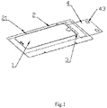
- a protective film includes a protective film sheet 1, a protective layer 2 and a release layer 3.
- the protective layer 2 is provided with a positioning mechanism 21 to align the protective film sheet 1 with a screen of an electronic device.
- the protective film is used in tandem with a film pasting machine, so as to ensure that the protective film sheet 1 is precisely pasted on the screen of the electronic device.
- the positioning mechanism 21 includes a plurality of positioning holes 210 arranged at intervals along a periphery of the protective film sheet 1 for positioning the protective film 10, and the positioning holes 210 are matched with a positioning device 20 to position the protective film 10, so that the positioning is precise and stable.
- a lead tab 4 is connected to an end part of the release layer 3 attached to the protective film sheet 1, which facilitates driving the release layer 3 to be peeled from the protective film sheet 1 during film pasting, so that the peeling is smoother and more efficient.
- the plurality of the positioning holes 210 comprise at least two diameters, and the positioning holes 210 of the two diameters are arranged in an array with each other, which facilitates distinguishing a positioning direction of the protective film 10.
- the plurality of positioning holes 210 are asymmetrically arranged with each other, or are distributed in a staggered manner, thereby further ensuring that the protective film 10 is in a correct positioning direction when in use.
- a boundary of the protective layer 2 is larger than a boundary of the protective film sheet 1 as a whole, which facilitates arranging the positioning holes 210 in the protective layer 2 to position the protective film 10.
- the protective layer 2 may also be attached with a positioning layer having the positioning holes 210 to position the protective film 10.
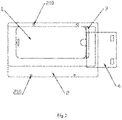
- the lead tab 4 includes a first layer 41 and a second layer 42, and one end of the release layer 3 is sandwiched between the first layer 41 and the second layer 42, so that the connection is more stable.
- one end of the lead tab 4 matched with the release layer 3 is offset from the boundary of the protective film sheet 1, and the lead tab 4 and the release layer 3 do not coincide with each other and have a small gap, which can ensure stable attachment of an area where the release layer 3 is matched with the protective film sheet 1 when the protective film 10 is not in use.
- the lead tab 4 is a hard layer, which is less prone to deformation than the release layer 3.
- the release layer 3 will have a bending and deformation tendency, so that the release layer 3 is peeled from the protective film sheet 1 more easily.
- the lead tab 4 is provided with an aligning mechanism 43.
- the lead tab 4 and the release layer 3 may be positioned by means of an aligning device 40 matched with the aligning mechanism 43, and the release layer 3 is collected.
- the aligning mechanism 43 is arranged at one end of the lead tab 4 away from the release layer 3, and positions the lead tab 4 before the release layer 3 is peeled, thereby avoiding the release layer 3 from disengagement or bending and jumping during peeling, which affects the quality of peeling.
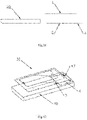
- a dimension of the release layer 3 in a width direction is basically the same as that of the protective film sheet 1, and a dimension of the release layer in a length direction is larger than that of the protective film sheet 1.
- the lead tab 4 is connected to the end part of the release layer 3 attached to the protective film sheet, which facilitates driving the release layer 3 to be peeled along a length direction of the protective film sheet 1 during film pasting, so that the peeling is smoother and more efficient.
- the lead tab 4 may also be arranged at one end of the release layer 3 in the width direction, which facilitates peeling the release layer 3 along the width direction thereof.
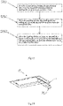
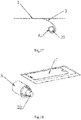
- FIG. 3 shows a method for peeling a release layer of a protective film according to an embodiment of the present invention. The method includes the following steps.
- a positioning device 20 is provided, and the positioning device 20 is matched with a positioning mechanism 21 to position the protective film 10, as shown in FIG. 4 .
- a peeling device 30 presses down a lead tab 4 to peel the lead tab from the protective film 10.
- a release layer 3 will have a bending and deformation tendency, so that the release layer 3 is peeled from a protective film sheet 1 more easily.
- a peeling device 30 moves relative to one end of the protective film sheet 1 away from the lead tab 4 and presses down the release layer 3 to peel the release layer 3 from the protective film sheet 1.
- the peeling device 30 drives the release layer 3 to be gradually peeled from the protective film sheet 1 while moving relative to the protective film sheet 1 and pressing down.
- an aligning mechanism 43 maintains a matching state with an aligning device 40 during movement of the peeling device 30, and positions the lead tab 4 and the release layer 3, so as to avoid the release layer 3 from disengagement or bending and jumping during peeling, which affects the quality of peeling.
- FIG. 12 shows a method for peeling a release layer of a protective film according to another embodiment of the present invention. The method includes the following steps.
- a positioning device 20 is provided, and the positioning device 20 is matched with a positioning mechanism 21 to position the protective film 10.
- a peeling device 30 is provided, and the peeling device 30 rolls up a lead tab 4 to peel the lead tab from the protective film 10.
- the peeling device 30 is a roller, the roller and/or the lead tab 4 are adhesive, the roller and the lead tab are adhered to each other when in contact, and the roller rolls up the lead tab 4.
- a peeling device 30 moves relative to one end of a protective film sheet 1 away from the lead tab 4 and rolls up the release layer 3 to peel the release layer 3 from the protective film sheet 1. As shown in FIG. 15 to FIG. 18 , the roller moves relative to the protective film sheet 1 and rolls up the release layer 3, so that the release layer 3 is gradually peeled from the protective film sheet 1.
- a process of peeling the release layer 3 is smoother and more efficient, thereby further increasing an efficiency and the quality of film pasting.
Landscapes
- Engineering & Computer Science (AREA)
- Mechanical Engineering (AREA)
- Manufacturing & Machinery (AREA)
- Laminated Bodies (AREA)
- Non-Metallic Protective Coatings For Printed Circuits (AREA)
- Folding Of Thin Sheet-Like Materials, Special Discharging Devices, And Others (AREA)
Claims (9)
- Schutzfilm (10), umfassend:eine Schutzfilmfolie (1);eine Schutzschicht (2);eine Ablöseschicht (3);wobei die Schutzfilmfolie (1) zwischen der Schutzschicht (2) und der Ablöseschicht (3) angeordnet ist;eine Leitlasche (4), welche mit einem Endteil der Ablöseschicht (3) verbunden ist, undeinen Positionierungsmechanismus (21), welcher auf der Schutzschicht (2) angeordnet ist, um die Schutzfilmfolie (1) mit einem Bildschirm einer elektronischen Vorrichtung auszurichten,wobei:die Leitlasche (4) eine erste Schicht (41) und eine zweite Schicht (42) umfasst, ein Ende der Ablöseschicht (3) zwischen der ersten Schicht (41) und der zweiten Schicht (42) eingelegt ist, und ein Ende der Leitlasche (4), welches mit der Ablöseschicht (3) übereinstimmt, in Bezug auf eine Grenze der Schutzfilmfolie (1) versetzt ist; unddie Leitlasche (4) weniger anfällig für die Verformung als die Ablöseschicht (3) ist, sodass, wenn die Leitlasche (4) vom Schutzfilm (10) abgelöst wird, die Ablöseschicht (3) eine Neigung zur Biegung und Verformung hat, wodurch das Ablösen der Ablöseschicht (3) von der Schutzfilmfolie (1) erleichtert wird.
- Schutzfilm (10) nach Anspruch 1, wobei ein Ausrichtungsmechanismus (43) auf der Leitlasche (4) angeordnet ist.
- Schutzfilm (10) nach Anspruch 2, wobei der Ausrichtungsmechanismus (43) an einem Ende der Leitlasche (4), welches entfernt von der Ablöseschicht (3) liegt, angeordnet ist.
- Schutzfilm (10) nach Anspruch 1, wobei der Positionierungsmechanismus (21) eine Vielzahl von Positionierungslöchern (210) umfasst, welche in Abständen entlang eines Umfangs der Schutzfilmfolie (1) zum Positionieren des Schutzfilms (10) angeordnet sind.
- Schutzfilm (10) nach Anspruch 4, wobei die Vielzahl von Positionierungslöchern (210) asymmetrisch miteinander angeordnet sind.
- Schutzfilm (10) nach Anspruch 5, wobei die Vielzahl von Positionierungslöchern (210) mindestens zwei Durchmesser umfassen und in einer Aufstellung miteinander angeordnet sind.
- Verfahren zum Ablösen einer Ablöseschicht eines Schutzfilms, umfassend:• das Bereitstellen (S101) einer Positionierungsvorrichtung (20), wobei die Positionierungsvorrichtung (20) auf einen Positionierungsmechanismus (21) abgestimmt ist, um den Schutzfilm (10) zu positionieren;• das Bereitstellen (S102) einer Ablösevorrichtung (30), wobei die Ablösevorrichtung (30) eine Leitlasche (4) vom Schutzfilm (10) ablöst; und• das Bewegen (S103) der Ablösevorrichtung (30) bezüglich des Schutzfilms (10), um die Ablöseschicht (3) von einer Schutzfilmfolie (1) des Schutzfilms (10) abzulösen,• wobei die Schutzfilmfolie (1) zwischen einer Schutzschicht (2) und der Ablöseschicht (3) angeordnet ist, wobei die Leitlasche (4) mit einem Endteil der Ablöseschicht (3) verbunden ist, und wobei der Positionierungsmechanismus (21) auf der Schutzschicht (2) angeordnet ist, um die Schutzfilmfolie (1) mit einem Bildschirm einer elektronischen Vorrichtung auszurichten,wobei:die Leitlasche (4) eine erste Schicht (41) und eine zweite Schicht (42) umfasst, ein Ende der Ablöseschicht (3) zwischen der ersten Schicht (41) und der zweiten Schicht (42) eingelegt ist, und ein Ende der Leitlasche (4), welches mit der Ablöseschicht (3) übereinstimmt, in Bezug auf eine Grenze der Schutzfilmfolie (1) versetzt ist; unddie Leitlasche (4) weniger anfällig für die Verformung als die Ablöseschicht (3) ist, sodass, wenn die Leitlasche (4) vom Schutzfilm (10) abgelöst wird, die Ablöseschicht (3) eine Neigung zur Biegung und Verformung hat, wodurch das Ablösen der Ablöseschicht (3) von der Schutzfilmfolie (1) erleichtert wird.
- Verfahren nach Anspruch 7, wobei das Bewegen der Ablösevorrichtung (30) bezüglich des Schutzfilms (10), um die Ablöseschicht (3) von der Schutzfilmfolie (1) abzulösen, Folgendes umfasst: das Bewegen der Ablösevorrichtung (30) bezüglich eines Endes der Schutzfilmfolie (1), welches entfernt von der Leitlasche (4) liegt, und das Herunterdrücken der Ablöseschicht (3), um die Ablöseschicht (3) von der Schutzfilmfolie (1) abzulösen.
- Verfahren nach Anspruch 7, wobei das Bewegen der Ablösevorrichtung (30) bezüglich des Schutzfilms, um die Ablöseschicht (3) von der Schutzfilmfolie (1) abzulösen, Folgendes umfasst: das Bewegen der Ablösevorrichtung (30) bezüglich eines Endes der Schutzfilmfolie (1), welches entfernt von der Leitlasche (4) liegt, und das Aufrollen der Ablöseschicht (3), um die Ablöseschicht (3) von der Schutzfilmfolie (1) abzulösen.
Applications Claiming Priority (2)
| Application Number | Priority Date | Filing Date | Title |
|---|---|---|---|
| CN201811363449.9A CN109624426A (zh) | 2018-11-14 | 2018-11-14 | 一种保护膜及其离型层剥离方法 |
| PCT/CN2018/124668 WO2020098108A1 (zh) | 2018-11-14 | 2018-12-28 | 一种保护膜及其离型层剥离方法 |
Publications (3)
| Publication Number | Publication Date |
|---|---|
| EP3800044A1 EP3800044A1 (de) | 2021-04-07 |
| EP3800044A4 EP3800044A4 (de) | 2021-09-01 |
| EP3800044B1 true EP3800044B1 (de) | 2022-11-23 |
Family
ID=66068063
Family Applications (1)
| Application Number | Title | Priority Date | Filing Date |
|---|---|---|---|
| EP18940443.7A Active EP3800044B1 (de) | 2018-11-14 | 2018-12-28 | Schutzfilm und verfahren zum ablösen der ablöseschicht davon |
Country Status (6)
| Country | Link |
|---|---|
| US (1) | US11541632B2 (de) |
| EP (1) | EP3800044B1 (de) |
| JP (1) | JP2021529710A (de) |
| CN (1) | CN109624426A (de) |
| AU (1) | AU2018449780B2 (de) |
| WO (1) | WO2020098108A1 (de) |
Families Citing this family (5)
| Publication number | Priority date | Publication date | Assignee | Title |
|---|---|---|---|---|
| CN109971383A (zh) * | 2019-04-30 | 2019-07-05 | 东莞捷邦实业有限公司 | 具有两种不同厚度的平板电脑前双摄像头泡棉组件 |
| CN112388960A (zh) * | 2019-08-14 | 2021-02-23 | 深圳市邦尼贴智能科技有限公司 | 自助贴膜机以及其剥离方法 |
| CN212603417U (zh) * | 2020-04-10 | 2021-02-26 | 张平 | 屏幕保护膜组件和屏幕保护膜的贴膜器 |
| CN116922876B (zh) * | 2023-07-31 | 2024-01-30 | 捷邦精密科技股份有限公司 | 一种帮助剥离的反贴层 |
| JP7572527B1 (ja) | 2023-10-06 | 2024-10-23 | Sb C&S株式会社 | 治具セット |
Family Cites Families (31)
| Publication number | Priority date | Publication date | Assignee | Title |
|---|---|---|---|---|
| JP3145262B2 (ja) * | 1994-02-16 | 2001-03-12 | シャープ株式会社 | 液晶表示素子 |
| CN101417525A (zh) * | 2007-10-26 | 2009-04-29 | 达信科技股份有限公司 | 剥膜机构及方法 |
| US9580626B2 (en) * | 2010-06-22 | 2017-02-28 | Zagg Intellectual Property Holding Co., Inc. | Systems for securing protective films to surfaces of substrates |
| US8905107B2 (en) * | 2011-02-18 | 2014-12-09 | Superior Communications | Protective material applicator device |
| US20130048203A1 (en) * | 2011-08-24 | 2013-02-28 | Targus International Group, Inc. | Film assemblies with removable opposing tabs and methods for applying the same |
| CN202987565U (zh) * | 2012-10-10 | 2013-06-12 | 林少裕 | 一种直板手机和平板电脑保护膜贴膜机 |
| TWM449696U (zh) * | 2012-11-13 | 2013-04-01 | Zhan-Rong Xu | 螢幕保護貼之diy貼合裝置 |
| CN103273716B (zh) * | 2013-05-29 | 2015-03-04 | 王旭辉 | 屏幕保护膜的贴膜方法及装置 |
| US9688016B2 (en) * | 2013-07-12 | 2017-06-27 | Advanced Wireless Innovations Llc | Protection module architecture and alignment tool, system, and method for protection module placement |
| US9902111B2 (en) * | 2013-08-08 | 2018-02-27 | Belkin International, Inc. | Cradle device, method of using the same, and overlay applicator machine |
| US10675817B2 (en) * | 2013-08-08 | 2020-06-09 | Belkin International, Inc. | Overlay applicator tray and method of using the same |
| WO2015021430A1 (en) * | 2013-08-08 | 2015-02-12 | Belkin International, Inc | Overlay applicator, applicator machine, and cradle, and method of providing and using the same |
| WO2015095856A1 (en) * | 2013-12-20 | 2015-06-25 | Belkin International, Inc. | Overlay applicator, applicator machine, and cradle, and method of providing and using the same |
| US10688712B2 (en) * | 2013-09-12 | 2020-06-23 | Alpha Comm Enterprises, Llc | Applicator for applying protective coverings to electronic device displays |
| WO2015038883A1 (en) * | 2013-09-12 | 2015-03-19 | Eshields, Llc | Protective covering applicator for electronic devices |
| KR101475650B1 (ko) * | 2014-01-14 | 2014-12-23 | 인하대학교 산학협력단 | 액정 필름 부착기 |
| CN204250612U (zh) * | 2014-01-17 | 2015-04-08 | 烟台正海科技有限公司 | 一种简易治具贴覆用保护膜结构 |
| US10105930B2 (en) * | 2014-02-18 | 2018-10-23 | Sharp Kabushiki Kaisha | Laminated film and film attachment method |
| CN105416661A (zh) * | 2014-09-04 | 2016-03-23 | 陈冠廷 | 屏幕保护膜贴合装置及方法 |
| CN204161653U (zh) * | 2014-09-04 | 2015-02-18 | 陈冠廷 | 屏幕保护膜贴合装置 |
| JP6547760B2 (ja) * | 2014-12-26 | 2019-07-24 | Agc株式会社 | 積層体の剥離開始部作成方法、及び剥離開始部作成装置並びに電子デバイスの製造方法 |
| CN104743156B (zh) * | 2015-03-16 | 2016-09-14 | 王旭辉 | 屏幕保护膜封闭式粘贴方法及装置 |
| JP6539340B2 (ja) * | 2015-04-13 | 2019-07-03 | トリニティ株式会社 | ディスプレイ画面へのフィルム貼り付け装置 |
| CN204750661U (zh) * | 2015-06-19 | 2015-11-11 | 王建峰 | 保护膜贴屏定位装置 |
| CN204776657U (zh) * | 2015-06-26 | 2015-11-18 | 群亿光电(深圳)有限公司 | 一种具有定位孔的保护贴膜 |
| JP2017161575A (ja) * | 2016-03-07 | 2017-09-14 | 株式会社バッファロー | 治具、および、システム |
| US9937690B2 (en) * | 2016-03-25 | 2018-04-10 | Coagent International Co., Ltd. | Two-stage application device for installing screen protectors and kit comprising the application device |
| US20180145715A1 (en) * | 2016-08-30 | 2018-05-24 | Microstrate Inc. | Tool for applying protective films to mobile communications devices |
| WO2018177590A1 (en) * | 2017-03-27 | 2018-10-04 | Schwenke Christopher | Device and method for applying protective films |
| CN108748969B (zh) * | 2018-07-12 | 2024-10-01 | 江门市艾加得电子有限公司 | 便携式贴膜机 |
| CN209426305U (zh) * | 2018-11-14 | 2019-09-24 | 江门市艾加得电子有限公司 | 一种保护膜 |
-
2018
- 2018-11-14 CN CN201811363449.9A patent/CN109624426A/zh active Pending
- 2018-12-28 EP EP18940443.7A patent/EP3800044B1/de active Active
- 2018-12-28 US US17/261,254 patent/US11541632B2/en active Active
- 2018-12-28 JP JP2020573459A patent/JP2021529710A/ja active Pending
- 2018-12-28 AU AU2018449780A patent/AU2018449780B2/en not_active Ceased
- 2018-12-28 WO PCT/CN2018/124668 patent/WO2020098108A1/zh not_active Ceased
Also Published As
| Publication number | Publication date |
|---|---|
| AU2018449780A1 (en) | 2021-01-28 |
| AU2018449780B2 (en) | 2022-05-19 |
| US20210268768A1 (en) | 2021-09-02 |
| CN109624426A (zh) | 2019-04-16 |
| JP2021529710A (ja) | 2021-11-04 |
| EP3800044A4 (de) | 2021-09-01 |
| US11541632B2 (en) | 2023-01-03 |
| WO2020098108A1 (zh) | 2020-05-22 |
| EP3800044A1 (de) | 2021-04-07 |
Similar Documents
| Publication | Publication Date | Title |
|---|---|---|
| EP3800044B1 (de) | Schutzfilm und verfahren zum ablösen der ablöseschicht davon | |
| KR101477020B1 (ko) | 테이프 부착 자동화 장치 | |
| EP1882584B1 (de) | Befestigungsstruktur für entfernbare schutzfläche und befestigungsfolie zur verwendung dabei | |
| JP4669269B2 (ja) | タッチパネル用保護フィルムの貼付け方法 | |
| CN103491209A (zh) | 一种一体式的触摸屏单面带胶泡棉及其加工方法 | |
| CN110016299A (zh) | 具有光晕效果的键盘胶带及其加工方法 | |
| CN115785836B (zh) | 一种多功能层状导电布双面胶组件及其生产工艺 | |
| CN111391295B (zh) | 一种贴膜装置 | |
| CN104915074A (zh) | 触控显示模块及其电子装置以及电子装置的组装方法 | |
| CN209426305U (zh) | 一种保护膜 | |
| CN202898308U (zh) | 背胶组合结构 | |
| CN218262362U (zh) | 一种多功能层状导电布双面胶组件 | |
| CN114476195B (zh) | 贴膜装置 | |
| CN105416663A (zh) | 自定位贴膜及使用方法 | |
| CN215970101U (zh) | 屏幕贴合辅助器以及屏幕保护组件 | |
| CN211339363U (zh) | 一种用于柔性电路板的双面胶带 | |
| CN114078366A (zh) | 显示屏组件的贴合治具及其贴合方法 | |
| CN219449612U (zh) | 一种用于电子产品精准定位的保护膜 | |
| CN212581802U (zh) | 一种高精度定位的易拉胶 | |
| CN210103829U (zh) | 一种笔记本键盘固定胶带 | |
| CN115442969A (zh) | 一种fpc补强片机贴方法 | |
| CN220700613U (zh) | 贴膜定位用离型膜 | |
| CN219991482U (zh) | 一种petg自粘膜 | |
| CN214705718U (zh) | 易撕贴组装治具 | |
| KR20060059605A (ko) | 가공 기판의 제조방법, 이를 이용한 평판 표시장치의제조방법 및 플렉시블 기판 가접합 장치 |
Legal Events
| Date | Code | Title | Description |
|---|---|---|---|
| STAA | Information on the status of an ep patent application or granted ep patent |
Free format text: STATUS: THE INTERNATIONAL PUBLICATION HAS BEEN MADE |
|
| PUAI | Public reference made under article 153(3) epc to a published international application that has entered the european phase |
Free format text: ORIGINAL CODE: 0009012 |
|
| STAA | Information on the status of an ep patent application or granted ep patent |
Free format text: STATUS: REQUEST FOR EXAMINATION WAS MADE |
|
| 17P | Request for examination filed |
Effective date: 20201231 |
|
| AK | Designated contracting states |
Kind code of ref document: A1 Designated state(s): AL AT BE BG CH CY CZ DE DK EE ES FI FR GB GR HR HU IE IS IT LI LT LU LV MC MK MT NL NO PL PT RO RS SE SI SK SM TR |
|
| AX | Request for extension of the european patent |
Extension state: BA ME |
|
| A4 | Supplementary search report drawn up and despatched |
Effective date: 20210804 |
|
| RIC1 | Information provided on ipc code assigned before grant |
Ipc: B32B 7/06 20190101AFI20210729BHEP Ipc: B32B 33/00 20060101ALI20210729BHEP Ipc: B32B 27/08 20060101ALI20210729BHEP |
|
| DAV | Request for validation of the european patent (deleted) | ||
| DAX | Request for extension of the european patent (deleted) | ||
| GRAP | Despatch of communication of intention to grant a patent |
Free format text: ORIGINAL CODE: EPIDOSNIGR1 |
|
| STAA | Information on the status of an ep patent application or granted ep patent |
Free format text: STATUS: GRANT OF PATENT IS INTENDED |
|
| INTG | Intention to grant announced |
Effective date: 20220803 |
|
| RIN1 | Information on inventor provided before grant (corrected) |
Inventor name: CHEN, HAIYING |
|
| GRAS | Grant fee paid |
Free format text: ORIGINAL CODE: EPIDOSNIGR3 |
|
| GRAA | (expected) grant |
Free format text: ORIGINAL CODE: 0009210 |
|
| STAA | Information on the status of an ep patent application or granted ep patent |
Free format text: STATUS: THE PATENT HAS BEEN GRANTED |
|
| AK | Designated contracting states |
Kind code of ref document: B1 Designated state(s): AL AT BE BG CH CY CZ DE DK EE ES FI FR GB GR HR HU IE IS IT LI LT LU LV MC MK MT NL NO PL PT RO RS SE SI SK SM TR |
|
| REG | Reference to a national code |
Ref country code: GB Ref legal event code: FG4D |
|
| REG | Reference to a national code |
Ref country code: CH Ref legal event code: EP |
|
| REG | Reference to a national code |
Ref country code: DE Ref legal event code: R096 Ref document number: 602018043517 Country of ref document: DE |
|
| REG | Reference to a national code |
Ref country code: AT Ref legal event code: REF Ref document number: 1532896 Country of ref document: AT Kind code of ref document: T Effective date: 20221215 |
|
| REG | Reference to a national code |
Ref country code: IE Ref legal event code: FG4D |
|
| REG | Reference to a national code |
Ref country code: LT Ref legal event code: MG9D |
|
| REG | Reference to a national code |
Ref country code: NL Ref legal event code: MP Effective date: 20221123 |
|
| REG | Reference to a national code |
Ref country code: AT Ref legal event code: MK05 Ref document number: 1532896 Country of ref document: AT Kind code of ref document: T Effective date: 20221123 |
|
| PG25 | Lapsed in a contracting state [announced via postgrant information from national office to epo] |
Ref country code: SE Free format text: LAPSE BECAUSE OF FAILURE TO SUBMIT A TRANSLATION OF THE DESCRIPTION OR TO PAY THE FEE WITHIN THE PRESCRIBED TIME-LIMIT Effective date: 20221123 Ref country code: PT Free format text: LAPSE BECAUSE OF FAILURE TO SUBMIT A TRANSLATION OF THE DESCRIPTION OR TO PAY THE FEE WITHIN THE PRESCRIBED TIME-LIMIT Effective date: 20230323 Ref country code: NO Free format text: LAPSE BECAUSE OF FAILURE TO SUBMIT A TRANSLATION OF THE DESCRIPTION OR TO PAY THE FEE WITHIN THE PRESCRIBED TIME-LIMIT Effective date: 20230223 Ref country code: LT Free format text: LAPSE BECAUSE OF FAILURE TO SUBMIT A TRANSLATION OF THE DESCRIPTION OR TO PAY THE FEE WITHIN THE PRESCRIBED TIME-LIMIT Effective date: 20221123 Ref country code: FI Free format text: LAPSE BECAUSE OF FAILURE TO SUBMIT A TRANSLATION OF THE DESCRIPTION OR TO PAY THE FEE WITHIN THE PRESCRIBED TIME-LIMIT Effective date: 20221123 Ref country code: ES Free format text: LAPSE BECAUSE OF FAILURE TO SUBMIT A TRANSLATION OF THE DESCRIPTION OR TO PAY THE FEE WITHIN THE PRESCRIBED TIME-LIMIT Effective date: 20221123 Ref country code: AT Free format text: LAPSE BECAUSE OF FAILURE TO SUBMIT A TRANSLATION OF THE DESCRIPTION OR TO PAY THE FEE WITHIN THE PRESCRIBED TIME-LIMIT Effective date: 20221123 |
|
| PG25 | Lapsed in a contracting state [announced via postgrant information from national office to epo] |
Ref country code: RS Free format text: LAPSE BECAUSE OF FAILURE TO SUBMIT A TRANSLATION OF THE DESCRIPTION OR TO PAY THE FEE WITHIN THE PRESCRIBED TIME-LIMIT Effective date: 20221123 Ref country code: PL Free format text: LAPSE BECAUSE OF FAILURE TO SUBMIT A TRANSLATION OF THE DESCRIPTION OR TO PAY THE FEE WITHIN THE PRESCRIBED TIME-LIMIT Effective date: 20221123 Ref country code: LV Free format text: LAPSE BECAUSE OF FAILURE TO SUBMIT A TRANSLATION OF THE DESCRIPTION OR TO PAY THE FEE WITHIN THE PRESCRIBED TIME-LIMIT Effective date: 20221123 Ref country code: IS Free format text: LAPSE BECAUSE OF FAILURE TO SUBMIT A TRANSLATION OF THE DESCRIPTION OR TO PAY THE FEE WITHIN THE PRESCRIBED TIME-LIMIT Effective date: 20230323 Ref country code: HR Free format text: LAPSE BECAUSE OF FAILURE TO SUBMIT A TRANSLATION OF THE DESCRIPTION OR TO PAY THE FEE WITHIN THE PRESCRIBED TIME-LIMIT Effective date: 20221123 Ref country code: GR Free format text: LAPSE BECAUSE OF FAILURE TO SUBMIT A TRANSLATION OF THE DESCRIPTION OR TO PAY THE FEE WITHIN THE PRESCRIBED TIME-LIMIT Effective date: 20230224 |
|
| P01 | Opt-out of the competence of the unified patent court (upc) registered |
Effective date: 20230522 |
|
| PG25 | Lapsed in a contracting state [announced via postgrant information from national office to epo] |
Ref country code: NL Free format text: LAPSE BECAUSE OF FAILURE TO SUBMIT A TRANSLATION OF THE DESCRIPTION OR TO PAY THE FEE WITHIN THE PRESCRIBED TIME-LIMIT Effective date: 20221123 |
|
| PG25 | Lapsed in a contracting state [announced via postgrant information from national office to epo] |
Ref country code: SM Free format text: LAPSE BECAUSE OF FAILURE TO SUBMIT A TRANSLATION OF THE DESCRIPTION OR TO PAY THE FEE WITHIN THE PRESCRIBED TIME-LIMIT Effective date: 20221123 Ref country code: RO Free format text: LAPSE BECAUSE OF FAILURE TO SUBMIT A TRANSLATION OF THE DESCRIPTION OR TO PAY THE FEE WITHIN THE PRESCRIBED TIME-LIMIT Effective date: 20221123 Ref country code: EE Free format text: LAPSE BECAUSE OF FAILURE TO SUBMIT A TRANSLATION OF THE DESCRIPTION OR TO PAY THE FEE WITHIN THE PRESCRIBED TIME-LIMIT Effective date: 20221123 Ref country code: DK Free format text: LAPSE BECAUSE OF FAILURE TO SUBMIT A TRANSLATION OF THE DESCRIPTION OR TO PAY THE FEE WITHIN THE PRESCRIBED TIME-LIMIT Effective date: 20221123 Ref country code: CZ Free format text: LAPSE BECAUSE OF FAILURE TO SUBMIT A TRANSLATION OF THE DESCRIPTION OR TO PAY THE FEE WITHIN THE PRESCRIBED TIME-LIMIT Effective date: 20221123 |
|
| REG | Reference to a national code |
Ref country code: CH Ref legal event code: PL |
|
| REG | Reference to a national code |
Ref country code: DE Ref legal event code: R097 Ref document number: 602018043517 Country of ref document: DE Ref country code: BE Ref legal event code: MM Effective date: 20221231 |
|
| PG25 | Lapsed in a contracting state [announced via postgrant information from national office to epo] |
Ref country code: SK Free format text: LAPSE BECAUSE OF FAILURE TO SUBMIT A TRANSLATION OF THE DESCRIPTION OR TO PAY THE FEE WITHIN THE PRESCRIBED TIME-LIMIT Effective date: 20221123 Ref country code: LU Free format text: LAPSE BECAUSE OF NON-PAYMENT OF DUE FEES Effective date: 20221228 Ref country code: AL Free format text: LAPSE BECAUSE OF FAILURE TO SUBMIT A TRANSLATION OF THE DESCRIPTION OR TO PAY THE FEE WITHIN THE PRESCRIBED TIME-LIMIT Effective date: 20221123 |
|
| PLBE | No opposition filed within time limit |
Free format text: ORIGINAL CODE: 0009261 |
|
| STAA | Information on the status of an ep patent application or granted ep patent |
Free format text: STATUS: NO OPPOSITION FILED WITHIN TIME LIMIT |
|
| GBPC | Gb: european patent ceased through non-payment of renewal fee |
Effective date: 20230223 |
|
| PG25 | Lapsed in a contracting state [announced via postgrant information from national office to epo] |
Ref country code: LI Free format text: LAPSE BECAUSE OF NON-PAYMENT OF DUE FEES Effective date: 20221231 Ref country code: IE Free format text: LAPSE BECAUSE OF NON-PAYMENT OF DUE FEES Effective date: 20221228 Ref country code: CH Free format text: LAPSE BECAUSE OF NON-PAYMENT OF DUE FEES Effective date: 20221231 |
|
| 26N | No opposition filed |
Effective date: 20230824 |
|
| PG25 | Lapsed in a contracting state [announced via postgrant information from national office to epo] |
Ref country code: SI Free format text: LAPSE BECAUSE OF FAILURE TO SUBMIT A TRANSLATION OF THE DESCRIPTION OR TO PAY THE FEE WITHIN THE PRESCRIBED TIME-LIMIT Effective date: 20221123 Ref country code: FR Free format text: LAPSE BECAUSE OF NON-PAYMENT OF DUE FEES Effective date: 20230123 Ref country code: BE Free format text: LAPSE BECAUSE OF NON-PAYMENT OF DUE FEES Effective date: 20221231 |
|
| PG25 | Lapsed in a contracting state [announced via postgrant information from national office to epo] |
Ref country code: GB Free format text: LAPSE BECAUSE OF NON-PAYMENT OF DUE FEES Effective date: 20230223 |
|
| PG25 | Lapsed in a contracting state [announced via postgrant information from national office to epo] |
Ref country code: GB Free format text: LAPSE BECAUSE OF NON-PAYMENT OF DUE FEES Effective date: 20230223 |
|
| PG25 | Lapsed in a contracting state [announced via postgrant information from national office to epo] |
Ref country code: CY Free format text: LAPSE BECAUSE OF FAILURE TO SUBMIT A TRANSLATION OF THE DESCRIPTION OR TO PAY THE FEE WITHIN THE PRESCRIBED TIME-LIMIT Effective date: 20221123 |
|
| PG25 | Lapsed in a contracting state [announced via postgrant information from national office to epo] |
Ref country code: MK Free format text: LAPSE BECAUSE OF FAILURE TO SUBMIT A TRANSLATION OF THE DESCRIPTION OR TO PAY THE FEE WITHIN THE PRESCRIBED TIME-LIMIT Effective date: 20221123 Ref country code: IT Free format text: LAPSE BECAUSE OF FAILURE TO SUBMIT A TRANSLATION OF THE DESCRIPTION OR TO PAY THE FEE WITHIN THE PRESCRIBED TIME-LIMIT Effective date: 20221123 Ref country code: HU Free format text: LAPSE BECAUSE OF FAILURE TO SUBMIT A TRANSLATION OF THE DESCRIPTION OR TO PAY THE FEE WITHIN THE PRESCRIBED TIME-LIMIT; INVALID AB INITIO Effective date: 20181228 |
|
| PG25 | Lapsed in a contracting state [announced via postgrant information from national office to epo] |
Ref country code: MC Free format text: LAPSE BECAUSE OF FAILURE TO SUBMIT A TRANSLATION OF THE DESCRIPTION OR TO PAY THE FEE WITHIN THE PRESCRIBED TIME-LIMIT Effective date: 20221123 |
|
| PG25 | Lapsed in a contracting state [announced via postgrant information from national office to epo] |
Ref country code: MC Free format text: LAPSE BECAUSE OF FAILURE TO SUBMIT A TRANSLATION OF THE DESCRIPTION OR TO PAY THE FEE WITHIN THE PRESCRIBED TIME-LIMIT Effective date: 20221123 |
|
| PG25 | Lapsed in a contracting state [announced via postgrant information from national office to epo] |
Ref country code: BG Free format text: LAPSE BECAUSE OF FAILURE TO SUBMIT A TRANSLATION OF THE DESCRIPTION OR TO PAY THE FEE WITHIN THE PRESCRIBED TIME-LIMIT Effective date: 20221123 |
|
| PG25 | Lapsed in a contracting state [announced via postgrant information from national office to epo] |
Ref country code: MT Free format text: LAPSE BECAUSE OF FAILURE TO SUBMIT A TRANSLATION OF THE DESCRIPTION OR TO PAY THE FEE WITHIN THE PRESCRIBED TIME-LIMIT Effective date: 20221123 |
|
| PG25 | Lapsed in a contracting state [announced via postgrant information from national office to epo] |
Ref country code: TR Free format text: LAPSE BECAUSE OF FAILURE TO SUBMIT A TRANSLATION OF THE DESCRIPTION OR TO PAY THE FEE WITHIN THE PRESCRIBED TIME-LIMIT Effective date: 20221123 |
|
| PGFP | Annual fee paid to national office [announced via postgrant information from national office to epo] |
Ref country code: DE Payment date: 20251210 Year of fee payment: 8 |