EP3798057B1 - Beleuchtungssystem für den kabineninnenraum eines fahrzeugs - Google Patents
Beleuchtungssystem für den kabineninnenraum eines fahrzeugs Download PDFInfo
- Publication number
- EP3798057B1 EP3798057B1 EP20193704.2A EP20193704A EP3798057B1 EP 3798057 B1 EP3798057 B1 EP 3798057B1 EP 20193704 A EP20193704 A EP 20193704A EP 3798057 B1 EP3798057 B1 EP 3798057B1
- Authority
- EP
- European Patent Office
- Prior art keywords
- lighting
- lighting system
- led lamps
- leds
- diffuser layer
- Prior art date
- Legal status (The legal status is an assumption and is not a legal conclusion. Google has not performed a legal analysis and makes no representation as to the accuracy of the status listed.)
- Active
Links
Images


Classifications
-
- B—PERFORMING OPERATIONS; TRANSPORTING
- B64—AIRCRAFT; AVIATION; COSMONAUTICS
- B64D—EQUIPMENT FOR FITTING IN OR TO AIRCRAFT; FLIGHT SUITS; PARACHUTES; ARRANGEMENT OR MOUNTING OF POWER PLANTS OR PROPULSION TRANSMISSIONS IN AIRCRAFT
- B64D11/00—Passenger or crew accommodation; Flight-deck installations not otherwise provided for
-
- B—PERFORMING OPERATIONS; TRANSPORTING
- B60—VEHICLES IN GENERAL
- B60Q—ARRANGEMENT OF SIGNALLING OR LIGHTING DEVICES, THE MOUNTING OR SUPPORTING THEREOF OR CIRCUITS THEREFOR, FOR VEHICLES IN GENERAL
- B60Q3/00—Arrangement of lighting devices for vehicle interiors; Lighting devices specially adapted for vehicle interiors
- B60Q3/40—Arrangement of lighting devices for vehicle interiors; Lighting devices specially adapted for vehicle interiors specially adapted for specific vehicle types
- B60Q3/41—Arrangement of lighting devices for vehicle interiors; Lighting devices specially adapted for vehicle interiors specially adapted for specific vehicle types for mass transit vehicles, e.g. buses
- B60Q3/43—General lighting
-
- B—PERFORMING OPERATIONS; TRANSPORTING
- B60—VEHICLES IN GENERAL
- B60Q—ARRANGEMENT OF SIGNALLING OR LIGHTING DEVICES, THE MOUNTING OR SUPPORTING THEREOF OR CIRCUITS THEREFOR, FOR VEHICLES IN GENERAL
- B60Q3/00—Arrangement of lighting devices for vehicle interiors; Lighting devices specially adapted for vehicle interiors
- B60Q3/70—Arrangement of lighting devices for vehicle interiors; Lighting devices specially adapted for vehicle interiors characterised by the purpose
- B60Q3/74—Arrangement of lighting devices for vehicle interiors; Lighting devices specially adapted for vehicle interiors characterised by the purpose for overall compartment lighting; for overall compartment lighting in combination with specific lighting, e.g. room lamps with reading lamps
- B60Q3/745—Arrangement of lighting devices for vehicle interiors; Lighting devices specially adapted for vehicle interiors characterised by the purpose for overall compartment lighting; for overall compartment lighting in combination with specific lighting, e.g. room lamps with reading lamps using lighting panels or mats, e.g. electro-luminescent panels, LED mats
-
- B—PERFORMING OPERATIONS; TRANSPORTING
- B64—AIRCRAFT; AVIATION; COSMONAUTICS
- B64D—EQUIPMENT FOR FITTING IN OR TO AIRCRAFT; FLIGHT SUITS; PARACHUTES; ARRANGEMENT OR MOUNTING OF POWER PLANTS OR PROPULSION TRANSMISSIONS IN AIRCRAFT
- B64D11/00—Passenger or crew accommodation; Flight-deck installations not otherwise provided for
- B64D2011/0038—Illumination systems for cabins as a whole
Definitions
- the present invention relates to a lighting system for the interior of a vehicle, in particular the cabin interior of an aircraft.
- aircraft cabins are equipped with a variety of functional linings.
- a wide variety of variants have been established for interior lighting in particular, depending on requirements and equipment.
- aircraft cabins have a combination of a variety of different types of lighting.
- a combination of point lighting and indirect area lighting is often provided in the ceiling area for general cabin lighting.
- Indirect lighting is also often provided on the side panels, as well as further point lighting in the form of reading lamps or table lighting, as well as individual lighting fixtures that can be individually controlled by a user or passenger.
- a variety of technical lighting and emergency lights (such as illuminated arrows that show the shortest route to an emergency exit in an emergency) are also provided for safety purposes. For this reason, it is necessary to determine the position of the lighting fixtures, especially the ceiling lighting, at the early stages of the planning phase of cabin equipment and to take this into account when manufacturing the cabin lining elements.
- the object of the invention is to provide an improved lighting system that enables large-area and small-scale lighting and significantly reduces the planning effort for lighting concepts.
- the invention proposes a lighting system having the features of claim 1. Further preferred developments can be found in the subclaims, the figures and the associated description.
- a lighting system comprising a housing with a mounting side and an opposite lighting side, a plurality of LED lighting means, a carrier layer arranged on the mounting side, wherein the plurality of LED lighting means are arranged in a net-like matrix structure on the carrier layer, wherein control elements and energy supply elements for signaling control and electrical supply of the LED lamps are arranged on the carrier layer, wherein a translucent diffuser layer is arranged at a distance from the carrier layer with the LED lamps and forms a luminous surface of the lighting side.
- the structure according to the invention enables surface lighting.
- the LEDs By arranging the LEDs appropriately and covering the housing with the special diffuser layer, it is possible for the surface of the lighting side itself to be used as a high-intensity luminous surface.
- the lighting system can be used both as decorative lighting and as technical lighting.
- the individual lighting elements can be controlled individually so that only certain defined areas light up or the entire surface lights up.
- a suitable distance between the translucent, i.e. opaque, but still translucent diffuser layer a homogeneous light emission is created in which the individual LED lamps are no longer individually visible as luminous points from an observer.
- the housing of the lighting system has a flat structure, whereby the exact dimensions can be freely selected over large areas and shapes.
- the entire ceiling area or side paneling of the cabin can be covered with a lighting system according to the invention.
- the shape can then be freely adapted so that the necessary recesses for the windows or luggage compartments or emergency hatches with safety devices such as oxygen masks are provided.
- the lighting housing itself forms the interior paneling of the cabin.
- the lighting system is scalable so that large areas can be formed from individual adapted housings or modularly from several smaller units. Overall, the number of different relevant lighting scenarios can be significantly increased with the lighting system.
- the position of the lighting fixtures does not have to be determined at the beginning of the planning phase of an interior project, but can be determined later, even after the interior of a vehicle has been completed, and can be adjusted at any time.
- the LED lamps are preferably RGB LEDs and white LEDs.
- An RGB LED is essentially an LED lamp consisting of three color LEDs: red (R), green (G) and blue (B).
- An RGB LED can emit different colors by mixing these three primary colors and also changing the intensity.
- RGB LEDs and white LEDs in conjunction with the diffuser plate, a bright surface is created that can be controlled separately in individual areas and thus enables different lighting scenarios, from indirect lighting, dimming, spot lighting, white or colored lighting and can therefore be used for both decorative lighting and technical lighting.
- the ratio of the number of RGB LEDs to white LEDs in the lighting system is one to one.
- the distance between adjacent LED lamps in a first X direction is exactly as large as in a second Y direction perpendicular to the X direction. This leads to a uniform light distribution and increases the adaptability of the lighting system.
- the adaptability of the lighting system is further increased by the fact that RGB LEDs and white LEDs are arranged alternately in both the X and Y directions.
- the distance between two adjacent LED lamps is 0.7 cm to 6 cm and the density of the LED lamps on the carrier plate is 250 to 21,000 LEDs/m 2 .
- the LED lamps By arranging the LED lamps in this way, both decorative lighting and sufficient cabin lighting can be achieved. Furthermore, a higher lamp density enables more detailed lighting or a better representation of lighting patterns or small-scale lighting elements, for example orientation aids in the context of emergency lighting. For cabin areas in which less complexity is planned, for example only large-scale and area lighting, modules with a lower lamp density can lead to reduced material and cost expenditure.
- the translucent diffuser layer is arranged at a distance of 1 cm to 10 cm from the LED carrier layer. This enables the lighting system to have a flat structure overall and the diffuser layer ensures uniform radiation from the LED lamps behind it.
- the diffuser layer is curved. Particularly in the ceiling area, where the lighting element extends over a large area, it is advantageous that the diffuser layer is given structural internal stress by means of a suitable radius of curvature, which on the one hand means that visible fastening elements can be eliminated as far as possible and on the other hand structural stiffening is achieved, which reduces natural vibrations of the diffuser plate.
- the thickness of the diffuser layer according to the invention is 1 mm to 10 mm and particularly preferably 3 mm.
- the diffuser layer is preferably made of polycarbonate. This type of material enables the functional optical properties of the diffuser plate to be realized and also allows compliance with fire protection requirements. However, other materials approved for fire protection are also conceivable and are the subject of the disclosure of the invention, in particular fiber-reinforced plastics from the group of polyamines or flame-retardant composite materials made of epoxy resin and/or glass fiber fabric.
- the total height of the lighting system or the housing is preferably less than 10 cm.
- the flat and comparatively light structure allows large, plate-shaped lighting panels to be created, which are ideal for covering the entire surface of the cabin walls and ceilings.
- the housing of the lighting system can also be implemented as complex geometric 3D shapes, depending on the application.
- the lighting system is robust in terms of its overall structure and is not very susceptible to failure.
- the light points formed by the individual LED lamps can be controlled individually and individually regulated in terms of their activation, activation time, luminous intensity and luminous color.
- the lighting system can be used both as decorative lighting and for technical lighting. For example, only certain defined areas (for example above a dining table) can be illuminated, or areas can be illuminated not at all or more dimly.
- the illuminated area can also be operated like a monitor with moving content, so that animations (e.g. cloud animations) can be played in partial areas or over the entire area.
- an interaction device is provided for the lighting system, via which the lighting can be manually adjusted by a user using control software.
- Such an interaction device can be formed, for example, by a tablet or touchscreen computer, which is connected to the control electronics of the lighting system by means of signals and can be controlled over the entire surface or in defined sub-areas via the interaction device. It is therefore conceivable that audio signals, such as music, can be visually displayed as part of decorative and entertainment lighting, or that the lighting element can be used as a digital painting and drawing surface.
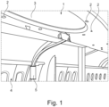
- the cabin interior lighting is implemented by a combination of different lighting elements.
- both point lighting 2 and indirect lighting elements 3 are provided.
- Indirect lighting elements 3 are also provided in the area of the side paneling 4.
- individual lighting elements 5 are used to emphasize individual decorative elements, such as a dining table.
- Such conventional lighting has limited flexibility, since the number, type and position of the lights must be determined early in the planning stage, and this can only be changed later with a high material and labor expenditure, since structural paneling components and supply lines must be changed or replaced.
- a combination of decorative lighting, technical lighting and animation is not possible.
- Both the ceiling area 1 and the side areas 4 are fully equipped with a lighting system according to the invention.
- a lighting system according to the invention As in Fig.2 in the side area 4, it is possible to realize a uniform indirect lighting 3 over the entire area.
- the lighting is not limited to this division; rather, the unlit areas 6 can also be controlled by the lighting system. It is also possible for only much smaller areas to be activated, for example to simulate point lighting. It is therefore possible to realize all known conventional lighting scenarios, but flexibly adaptable.
- the lighting system according to the invention can be operated with large-scale, monitor-like moving content, as in Fig.3 shown in side panel 4 with animation 7 of a cloudy sky.
- LED lamps 8, 9 are used as the light source. These can be controlled individually, so that a variety of lighting scenarios can be created, as in the Figs. 2 and 3 shown, can be realized.
- a translucent diffuser layer 10 is provided at a distance from the LED lamps 8, 9, which enables uniform radiation from the LED lamps 8, 9 located behind it. It is advantageous that RGB LEDs 8 and white LEDs 9 are used.
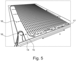
- the LED lamps 8, 9 are arranged in a net-like matrix structure ( Fig.5 ). These are arranged in a housing 11 for better assembly.
- the housing has a mounting side 12 and an opposite lighting side 13.
- the mounting side 12 is formed by a carrier layer 14 on which the LED lamps 8, 9 are arranged.
- the LED lamps 8, 9 are arranged on LED strips 15 for better assembly.
- the LED strips 15 are fixed with corresponding holding elements 16. All relevant control and energy supply devices 17 are also accommodated on the carrier layer 14.
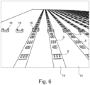
- the RGB LEDs 8 and the white LEDs 9 are preferably arranged alternately on the LED strips 15, the distances between the LED lamps 8, 9 on the LED strips 15 corresponding to the distance between two adjacent LED strips 15, so that a uniform network-like distribution is realized ( Fig.6 ).
- RGB LEDs 8 and white LEDs 9 can also be used on the LED strips 15. Although these have a lower light output overall, they result in a more harmonious overall light spectrum, so that a more natural color rendering, similar to the solar spectrum, is achieved. This more natural color spectrum is generally perceived as more pleasant by people.
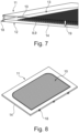
- the housing 11 comprises on the mounting side 12 a carrier layer 14 on which the LED lamps 8, 9 are arranged, mounting elements 18 for mounting the housing 11 on the wall paneling of an aircraft cabin and on the lighting side 13 a translucent diffuser layer 10.
- the diffuser layer 10 is preferably made of polycarbonate so that both uniform radiation from the LED lamps 8, 9 behind it and sufficient fire safety are guaranteed.
- the diffuser layer 10 is arranged at a distance from the LED matrix, whereby due to the large area of the diffuser layer 10, additional spacers 19 can be provided.
- the individual modules are scalable so that elements several meters in size can also be realized, with which the entire interior paneling of the cabin can be equipped.
- a combination of RGB LEDs 8 and white LEDs 9, or combined RGBW LEDs 8, 9 and the diffuser layer 10 a high luminosity is achieved with a low installation height. It is possible to stiffen the diffuser layer 10 by curving it using residual stress and thus reduce natural vibrations.
- the diffuser plate 10 is given inherent stress by means of a suitable radius.
- the radius is up to 400 cm, and the curvature and inherent stress mean that visible fastening elements can be dispensed with.
- the diffuser plate 10 has a thickness of around 3 mm, with the distance between the LED lamps 8, 9 and the diffuser layer 10 being 1 cm to 9 cm. This means that the overall height of the housing 11 can be less than 10 cm.
- the ratio of the RGB LEDs 8 to the white LEDs 9 is ideally one to one, with the LED density preferably being 250 to 21,000 LEDs per square meter.
- the structure can then be mounted on the ceiling with the lighting side 13 facing downwards.
- both decorative lighting and sufficient cabin lighting can be achieved.
- Cloud animations can be shown, for example.
- the activation time, lighting intensity, lighting color and lighting area can be set as desired. This means that precise prior planning of the positions of lighting elements is no longer necessary.
- Static or animated content can be displayed over a large area, which significantly changes the visual appearance of the cabin or serves as entertainment.
- the housing 11 and the resulting illuminated surface can be implemented as a flat or curved surface or in complex geometric 3D shapes.
Landscapes
- Engineering & Computer Science (AREA)
- Mechanical Engineering (AREA)
- Aviation & Aerospace Engineering (AREA)
- Arrangements Of Lighting Devices For Vehicle Interiors, Mounting And Supporting Thereof, Circuits Therefore (AREA)
- Non-Portable Lighting Devices Or Systems Thereof (AREA)
Description
- Die vorliegende Erfindung betrifft ein Beleuchtungssystem für den Innenraum eines Fahrzeugs, insbesondere den Kabineninnenraum eines Luftfahrzeugs.
- Je nach Bedarf sind Flugzeugkabinen mit einer Vielzahl von funktionellen Auskleidungen versehen. Insbesondere für die Innenraumbeleuchtung hat sich je nach Bedarf und Ausstattung eine große Variantenvielfalt etabliert. Allgemein sind in Flugzeugkabinen eine Kombination einer Vielzahl von unterschiedlichen Beleuchtungsformen vorhanden. So ist im Deckenbereich zur allgemeinen Kabinenausleuchtung oftmals eine Kombination von Punktbeleuchtung und indirekter Flächenbeleuchtung vorgesehen. Weiters ist oftmals indirekte Beleuchtung an den Seitenverkleidungen vorgesehen sowie weitere Punktbeleuchtung etwa in Form von Leselampen oder Tischbeleuchtung sowie individuelle Leuchtkörper, die von einem Benutzer, bzw. Passagier individuell steuerbar sind. Auch zu Sicherheitszwecken sind eine Vielzahl von technischen Beleuchtungen und Notfallleuchten (etwa Leuchtpfeile, die im Notfall den kürzesten Weg zu einem Notausstieg weisen) vorgesehen. Aus diesem Grund ist es notwendig, bereits im Anfangsstadium der Planungsphase einer Kabinenausstattung die Position der Leuchtkörper, insbesondere der Deckenbeleuchtung, festzulegen und für die Fertigung der Kabinenauskleidungselemente zu berücksichtigen.
- Eine Möglichkeit große Flächen, insbesondere die Deckenflächen indirekt zu beleuchten ist durch die Verwendung von Projektoren im Deckenbereich bekannt. Dabei kann eine Dekorationsbeleuchtung auf der Deckenfläche verwirklicht werden. Eine technische Hürde stellt hier jedoch ein flacher Einstrahlwinkel dar, weshalb projizierte Objekte mittels einer Software entzerrt werden müssen. Die Verwendung in Luftfahrzeugen ist aber auch wegen der entstehenden Vibrationen im Flugbetrieb problematisch. Außerdem ist eine derartige Beleuchtung lediglich zur Dekorationsbeleuchtung geeignet und nicht für technische Beleuchtung oder Notfallbeleuchtung.
- Aus der
US 10,392,129 B1 - Ferner offenbaren die Druckschriften
JP 2016-149264 A US 2008/0316740 A1 ,DE 10 2017 217 916 A1 undDE 10 2017 220 355 A1 Beleuchtungen mit einer Vielzahl an LEDs. - Vor diesem Hintergrund liegt der Erfindung die Aufgabe zugrunde, ein verbessertes Beleuchtungssystem bereitzustellen, das eine großflächige und kleinteilige Beleuchtung ermöglicht und den Planungsaufwand für Beleuchtungskonzepte erheblich reduziert.
- Zur Lösung der Aufgabe wird erfindungsgemäß ein Beleuchtungssystem mit den Merkmalen des Anspruchs 1 vorgeschlagen. Weitere bevorzugte Weiterentwicklungen sind den Unteransprüchen, den Figuren und der zugehörigen Beschreibung zu entnehmen.
- Gemäß dem Grundgedanken der Erfindung wird ein Beleuchtungssystem vorgeschlagen, umfassend ein Gehäuse mit einer Montageseite und einer gegenüberliegenden Beleuchtungsseite, einer Mehrzahl von LED-Leuchtmitteln, einer auf der Montageseite angeordneten Trägerschicht, wobei die Mehrzahl von LED-Leuchtmitteln in einer netzartigen Matrixstruktur auf der Trägerschicht angeordnet sind, wobei Steuerelemente und Energieversorgungselemente zur signaltechnischen Ansteuerung und elektrischen Versorgung der LED-Leuchtmittel auf der Trägerschicht angeordnet sind, wobei eine transluzente Diffusorschicht beabstandet von der Trägerschicht mit den LED-Leuchtmitteln angeordnet ist und eine Leuchtfläche der Beleuchtungsseite bildet.
- Der Vorteil der vorgeschlagenen Lösung ist darin zu sehen, dass durch den erfindungsgemäßen Aufbau eine Flächenbeleuchtung möglich wird. Durch eine geeignete Anordnung der LEDs und Abdeckung des Gehäuses mit der speziellen Diffusorschicht wird es möglich, dass die Oberfläche der Beleuchtungsseite selbst als Leuchtfläche in hoher Lichtstärke verwendet werden kann. Dadurch kann das Beleuchtungssystem sowohl als Dekorationsbeleuchtung als auch als technische Beleuchtung betrieben werden. Die einzelnen Leuchtelemente können dabei einzeln angesteuert werden, so dass nur bestimmte definierte Bereiche leuchten oder die ganze Fläche leuchtet. Durch die Wahl eines geeigneten Abstands zwischen der transluzenten, also opaken, aber dennoch lichtdurchlässigen Diffusorschicht entsteht eine homogene Lichtabstrahlung, bei der die einzelnen LED-Leuchtmittel als Leuchtpunkte von einem Betrachter aus nicht mehr individuell sichtbar sind. Durch den erfindungsgemäßen Aufbau hat das Gehäuse des Beleuchtungssystems einen flachen Aufbau, wobei die genauen Abmaße über große Flächen und Formen frei wählbar sind. So kann beispielsweise die gesamte Deckenfläche oder Seitenverkleidung der Kabine mit einem erfindungsgemäßen Beleuchtungssystem bedeckt sein. Die Form ist dann frei anpassbar, so dass nötige Aussparungen für die Fenster oder Gepäckfächer oder Notfallklappen mit Sicherheitsvorrichtungen wie Sauerstoffmasken vorgesehen sind. Das Beleuchtungsgehäuse an sich bildet in dem Fall selbst die Innenraumverkleidung der Kabine. Das Beleuchtungssystem ist skalierbar, so dass große Flächen von einzelnen angepassten Gehäusen oder modular durch mehrere kleinere Einheiten gebildet werden können. Insgesamt lässt sich die Anzahl verschiedener relevanter Beleuchtungsszenarien mit dem Beleuchtungssystem deutlich erhöhen.
- Auf diese Weise muss die Position der Leuchtkörper nicht am Anfang der Planungsphase eines Innenraumprojekts festgelegt werden, sondern kann später sogar nach Fertigstellung des Innenausbaus eines Fahrzeugs festgelegt werden und jederzeit angepasst werden.
- Vorzugsweise sind die LED-Leuchtmittel durch RGB-LEDs und wei-ße LEDs gebildet. Eine RGB-LED ist im Prinzip ein LED-Leuchtmittel bestehend aus drei Farb-LEDs: rot (R), grün (G) und blau (B). eine RGB-LED kann verschiedene Farben ausgeben, indem sie diese drei Grundfarben mischt und auch die Intensität ändert. Durch die Verwendung von RGB-LEDs und weißen LEDs in Verbindung mit der Diffusorplatte wird eine leuchtstarke Oberfläche gebildet, die in einzelnen Bereichen separat ansteuerbar ist und somit unterschiedliche Beleuchtungsszenarien, von indirekter Beleuchtung, Dimmung, punktuelle Beleuchtung, weiße oder farbliche Beleuchtung ermöglicht und dadurch sowohl für Dekorationsbeleuchtung als auch für technische Beleuchtung eingesetzt werden kann.
- Vorzugsweise ist das Verhältnis der Anzahl von RGB-LEDs zu weißen LEDs im Beleuchtungssystem eins zu eins. Erfindungsgemäß ist in der netzartigen Matrixstruktur der LED-Leuchtmittel der Abstand benachbarter LED-Leuchtmittel in einer ersten X-Richtung genau so groß wie in einer zweiten, senkrecht zur X-Richtung stehenden Y-Richtung. Dies führt zu einer gleichmäßigen Lichtverteilung und erhöht die Anpassbarkeit des Beleuchtungssystems.
- Weiter wird die Anpassbarkeit des Beleuchtungssystems dadurch erhöht, dass sowohl in X-Richtung als auch in Y-Richtung RGB-LEDs und weiße LEDs abwechselnd angeordnet sind.
- Erfindungsgemäß beträgt der Abstand zweier benachbarter LED-Leuchtmittel 0,7 cm bis 6 cm und die Dichte der LED-Leuchtmittel auf der Trägerplatte 250 bis 21000 LEDs/m2. Durch eine derartige Anordnung der LED-Leuchtmittel lassen sich sowohl eine Dekorationsbeleuchtung als auch eine ausreichende Kabinenbeleuchtung realisieren. Des Weiteren ermöglicht eine größere Leuchtmitteldichte eine detailliertere Beleuchtung, beziehungsweise eine bessere Darstellung von Beleuchtungsmustern oder kleinräumigen Beleuchtungselementen, beispielsweise Orientierungshilfen im Rahmen einer Notbeleuchtung. Für Kabinenbereiche, in denen eine geringere Komplexität geplant ist, beispielsweise nur großräumige und flächige Beleuchtung, können hingegen Module mit einer geringeren Leuchtmitteldichte zu reduziertem Material- und Kostenaufwand führen.
- Die transluzente Diffusorschicht ist erfindungsgemäß in einem Abstand von 1 cm bis 10 cm von der LED-Trägerschicht angeordnet. Dadurch wird zum einen ein insgesamt flacher Aufbau des Beleuchtungssystems ermöglicht und zum anderen sorgt die Diffusorschicht für eine gleichmäßige Abstrahlung der dahinter liegenden LED-Leuchtmittel.
- Weiter ist bevorzugt, dass die Diffusorschicht gewölbt ist. Insbesondere im Deckenbereich, wo sich das Beleuchtungselement über eine große Fläche erstreckt, ist es vorteilhaft, dass die Diffusorschicht durch einen geeigneten Radius einer Wölbung eine strukturelle Eigenspannung erhält, wodurch zum einen sichtbare Befestigungselemente möglichst entfallen können und zum anderen eine strukturelle Versteifung erreicht wird, wodurch Eigenschwingungen der Diffusorplatte verringert werden.
- Um eine ausreichende Stabilität zu gewährleisten, beträgt die Dicke der Diffusorschicht erfindungsgemäß 1 mm bis 10 mm und besonders bevorzugt 3 mm.
- Die Diffusorschicht ist bevorzugt aus Polycarbonat gebildet. Durch ein derartiges Material lassen sich die funktionellen optischen Eigenschaften der Diffusorplatte realisieren und zusätzlich lassen sich dadurch auch brandschutztechnische Vorgaben einhalten. Dabei sind aber auch weitere brandschutztechnisch zugelassene Materialien denkbar und Gegenstand der Erfindungsoffenbarung, insbesondere Faserkunststoffe aus der Gruppe der Polyamine oder schwer entflammbare Verbundwerkstoffe aus Epoxidharz und/oder Glasfasergewebe.
- Die Gesamthöhe des Beleuchtungssystems beziehungsweise des Gehäuses ist bevorzugt kleiner als 10 cm. Durch den flachen und vergleichsweise leichten Aufbau lassen sich großflächige, plattenförmige Beleuchtungspaneele realisieren, die sich gut zur vollflächigen Verkleidung der Kabinenwände und -decken eignen. Die Gehäuse des Beleuchtungssystems lassen sich alternativ aber auch je nach Anwendungsfall als komplexe geometrische 3D-Formen umsetzen. Das Beleuchtungssystem ist insgesamt hinsichtlich des Gesamtaufbaus robust und wenig störungsanfällig.
- Vorzugsweise sind die Leuchtpunkte, die durch die einzelnen LED-Leuchtmittel gebildet sind, einzeln ansteuerbar und hinsichtlich ihrer Aktivierung, Aktivierungszeit, Leuchtstärke und Leuchtfarbe individuell regelbar. Dadurch kann das Leuchtsystem sowohl als Dekorationsbeleuchtung, als auch zur technischen Beleuchtung eingesetzt werden. Dabei können etwa nur bestimmte definierte Bereiche (zum Beispiel über einem Esstisch) leuchten oder Bereiche gar nicht oder schwächer leuchten. Die Leuchtfläche kann auch monitorartig mit bewegten Inhalten betrieben werden, so dass in Teilbereichen oder vollflächig Animationen (zum Beispiel Wolkenanimationen) abgespielt werden können.
- In einer weiter bevorzugten Ausführungsform ist für das Beleuchtungssystem eine Interaktionsvorrichtung vorgesehen, über welche die Beleuchtung durch einen Benutzer mittels einer Steuerungssoftware manuell einstellbar ist. Dadurch besteht die Möglichkeit für einen Benutzer Einfluss auf die Beleuchtung zu nehmen. Eine derartige Interaktionsvorrichtung kann beispielsweise durch einen Tablet- oder Touchscreen Computer gebildet sein, der signaltechnisch mit der Steuerungselektronik des Beleuchtungssystems verbunden ist und vollflächig oder in definierten Teilbereichen über die Interaktionsvorrichtung steuerbar ist. So ist vorstellbar, dass im Rahmen einer Dekorations- und Entertainmentbeleuchtung Audiosignale, wie zum Beispiel Musik, visuell abgebildet werden, oder dass das Beleuchtungselement als digitale Mal- und Zeichenfläche verwendet werden kann.
- Die Erfindung wird im Folgenden anhand bevorzugter Ausführungsformen unter Bezugnahme auf die beigefügten Figuren erläutert. Dabei zeigt
- Fig. 1
- schematisch ein herkömmliches Beleuchtungsszenario einer Flugzeugkabine;
- Fig. 2
- schematisch ein Beleuchtungsszenario einer Flugzeugkabine mit einem erfindungsgemäßen Beleuchtungssystem;
- Fig. 3
- schematisch ein weiteres Beleuchtungsszenario einer Flugzeugkabine mit einem erfindungsgemäßen Beleuchtungssystem;
- Fig. 4
- schematisch die Funktionsweise eines erfindungsgemäßen Beleuchtungssystems;
- Fig. 5
- schematisch eine Trägerplatte mit darauf angeordneten LED-Leuchtmitteln;
- Fig. 6
- einen Teilausschnitt der Trägerplatte mit darauf angeordneten LED-Leuchtmitteln;
- Fig. 7
- einen Querschnitt des Gehäuses eines Moduls des erfindungsgemäßen Beleuchtungssystems;
- Fig. 8
- schematisch ein Modul des erfindungsgemäßen Beleuchtungssystems.
- Gemäß dem Stand der Technik wird, wie in
Fig. 1 dargestellt, die Kabineninnenbeleuchtung durch eine Kombination von verschiedenen Beleuchtungselementen realisiert. Dabei sind im Deckenbereich 1 der Kabine sowohl Punktbeleuchtung 2, als auch indirekte Beleuchtungselemente 3 vorgesehen. Ebenso sind im Bereich der Seitenverkleidung 4 indirekte Beleuchtungselemente 3 vorgesehen. Außerdem werden individuelle Leuchtkörper 5 verwendet, um einzelne dekorative Elemente zu betonen, wie beispielsweise einen Esstisch. Eine derartige konventionelle Beleuchtung weist eine eingeschränkte Flexibilität auf, da bereits hinsichtlich der Anzahl, Art und Position der Leuchten frühzeitig im Planungsstadium eine Festlegung erfolgen muss, die später nur mit hohem Material- und Arbeitsaufwand geändert werden kann, da strukturelle Verkleidungsbauteile und Versorgungsleitungen geändert, beziehungsweise ausgetauscht werden müssen. Zudem ist keine Kombination von Dekorationsbeleuchtung, technischer Beleuchtung und Animation möglich. - In den
Fign. 2 und 3 sind sowohl der Deckenbereich 1 als auch die Seitenbereiche 4 vollflächig mit einem erfindungsgemäßen Beleuchtungssystem ausgestattet. Wie inFig. 2 im Seitenbereich 4 ersichtlich, ist es möglich, über die gesamte Fläche eine gleichmäßige indirekte Beleuchtung 3 zu realisieren. Im Deckenbereich 1 ist hingegen nur ein Teilbereich 3 beleuchtet, während große Areale 6 unbeleuchtet sind. Die Beleuchtung ist jedoch nicht auf diese Einteilung festgelegt, vielmehr können auch die nicht beleuchteten Areale 6 vom Beleuchtungssystem angesteuert werden. Es ist ebenfalls möglich, dass nur wesentlich kleinere Bereiche aktiviert sind, um beispielsweise eine Punktbeleuchtung zu simulieren. Es ist also möglich, alle bekannten herkömmlichen Beleuchtungsszenarien zu realisieren, jedoch flexibel anpassbar. Zusätzlich kann das erfindungsgemä-ße Beleuchtungssystem mit großflächigen, monitorartigen bewegten Inhalten betrieben werden, wie inFig. 3 im Seitenbereich 4 mit der Animation 7 eines Wolkenhimmels gezeigt ist. - Die Funktionsweise des erfindungsgemäßen Beleuchtungssystems ist in
Fig. 4 vorgesehen. Dabei werden als Leuchtmittel LED-Leuchtmittel 8, 9 verwendet. Diese sind individuell ansteuerbar, so dass eine Vielzahl von Beleuchtungsszenarien wie in denFign. 2 und 3 dargestellt, realisiert werden kann. Von den LED-Leuchtmitteln 8, 9 beabstandet ist eine transluzente Diffusorschicht 10 vorgesehen, durch die eine gleichmäßige Abstrahlung der dahinterliegenden LED-Leuchtmittel 8, 9 ermöglicht wird. Es ist dabei vorteilhaft, dass RGB-LEDs 8 und wei-ße LEDs 9 verwendet werden. - Die LED-Leuchtmittel 8, 9 sind in einer netzartigen Matrixstruktur angeordnet (
Fig. 5 ). Diese sind zur besseren Montage in einem Gehäuse 11 angeordnet. Das Gehäuse weist eine Montageseite 12 und eine gegenüberliegende Beleuchtungsseite 13 auf. Die Montageseite 12 ist durch eine Trägerschicht 14 gebildet, auf der die LED-Leuchtmittel 8, 9 angeordnet sind. In dem dargestellten Ausführungsbeispiel sind die LED-Leuchtmittel 8, 9 zur besseren Montage auf LED-Streifen 15 angeordnet. Die LED-Streifen 15 sind dabei mit korrespondierenden Halteelementen 16 fixiert. Auf der Trägerschicht 14 sind außerdem alle relevanten Ansteuerungs- und Energieversorgungsvorrichtungen 17 untergebracht. Vorzugsweise sind die RGB-LEDs 8 und die weißen LEDs 9 abwechselnd auf den LED-Streifen 15 angeordnet, wobei die Abstände der LED-Leuchtmittel 8, 9 auf den LED-Streifen 15 dem Abstand zweier benachbarter LED-Streifen 15 entspricht, so dass eine gleichmäßige netzartige Verteilung realisiert ist (Fig. 6 ). Die Abstände der LED-Leuchtmittel 8, 9 in einer ersten X-Richtung sind also in etwa genau so groß wie auf einer zur X-Richtung senkrechten Y-Richtung. Alternativ zu RGB-LEDs 8 und weißen LEDs 9 können auf den LED-Streifen 15 auch kombinierte RGBW-LEDs (8, 9) eingesetzt werden. Diese haben zwar insgesamt eine geringere Lichtleistung, jedoch ergibt sich ein harmonischeres Gesamtlichtspektrum, so dass eine natürlichere Farbwiedergabe, ähnlich dem Sonnenspektrum, erreicht wird. Dieses natürlichere Farbspektrum wird in der Regel von Personen als angenehmer empfunden. - In den
Fign. 7, 8 ist ein Gehäuse 11 eines Moduls des Beleuchtungssystems im Querschnitt (Fig. 7 ) und im Ganzen (Fig. 8 ) dargestellt. Das Gehäuse 11 umfasst auf der Montageseite 12 eine Trägerschicht 14, auf der die LED-Leuchtmittel 8, 9 angeordnet sind, Montageelemente 18 zur Montage des Gehäuses 11 an der Wandverkleidung einer Flugzeugkabine und auf der Beleuchtungsseite 13 eine transluzente Diffusorschicht 10. Die Diffusorschicht 10 ist vorzugsweise aus Polycarbonat hergestellt, so dass sowohl eine gleichmäßige Abstrahlung der dahinter liegenden LED-Leuchtmittel 8, 9 als auch eine ausreichende Brandsicherheit gewährleistet ist. Die Diffusorschicht 10 ist beabstandet von der LED-Matrix angeordnet, wobei aufgrund der gro-ßen Fläche der Diffusorschicht 10 zusätzlich Abstandshalter 19 vorgesehen sein können. Die einzelnen Module sind skalierbar, so dass auch Elemente von mehreren Metern Ausdehnung realisiert werden können, womit die gesamte Innenverkleidung der Kabine ausgestattet werden kann. Durch die Verwendung einer Kombination von RGB-LEDs 8 und weißen LEDs 9, beziehungsweise von kombinierten RGBW-LEDs 8, 9 sowie der Diffusorschicht 10 wird eine hohe Leuchtstärke bei geringer Aufbauhöhe erreicht. Es besteht die Möglichkeit, die Diffusorschicht 10 durch Wölbung mittels Eigenspannung zu versteifen und so Eigenschwingungen zu reduzieren. - Insbesondere bei Verwendung in einer Flugzeugkabine als Deckendom, also mittels Deckenmontage, erhält die Diffusorplatte 10 durch einen geeigneten Radius eine Eigenspannung. Der Radius beträgt dabei bis zu 400 cm, durch die Wölbung und Eigenspannung kann auch auf sichtbare Befestigungselemente verzichtet werden. Die Diffusorplatte 10 hat in diesem Ausführungsbeispiel eine Stärke von etwa 3 mm, wobei der Abstand der LED-Leuchtmittel 8, 9 zu der Diffusorschicht 10 1 cm bis 9 cm beträgt. Das führt dazu, dass die Gesamthöhe des Gehäuses 11 kleiner als 10 cm ausgeführt werden kann. Das Verhältnis der RGB-LEDs 8 zu weißen LEDs 9 beträgt idealerweise eins zu eins, wobei die LED-Dichte vorzugsweise 250 bis 21000 LEDs pro Quadratmeter beträgt. Der Aufbau kann dann mit der Beleuchtungsseite 13 nach unten an der Decke montiert werden.
- Durch eine geeignete Einzelansteuerung der LED-Leuchtmittel 8, 9 kann sowohl eine Dekorationsbeleuchtung als auch eine ausreichende Kabinenbeleuchtung erreicht werden. Es können zum Beispiel Wolkenanimationen abgebildet werden. Die Aktivierungszeit, Beleuchtungsstärke, Beleuchtungsfarbe und der Beleuchtungsbereich können beliebig festgelegt werden. Dadurch kann eine exakte vorausgehende Planung der Positionen von Leuchtkörpern entfallen. Es können statische oder animierte Inhalte großflächig angezeigt werden, welche das optische Erscheinungsbild der Kabine deutlich verändern oder zum Entertainment dienen. Das Gehäuse 11 sowie die resultierende Leuchtfläche kann sowohl als ebene oder gewölbte Fläche als auch in komplexen geometrischen 3D-Formen umgesetzt werden.
Claims (11)
- Beleuchtungssystem für den Innenraum eines Fahrzeugs umfassend ein Gehäuse (11) mit einer Montageseite (12) und einer gegenüberliegenden Beleuchtungsseite (13),- einer Mehrzahl von LED-Leuchtmitteln (8,9),- einer auf der Montageseite (12) angeordneten Trägerschicht (14),wobei die Mehrzahl von LED-Leuchtmitteln (8,9) in einer netzartigen Matrixstruktur auf der Trägerschicht (14) angeordnet sind,wobei Steuerelemente und Energieversorgungselemente (17) zur signaltechnischen Ansteuerung und elektrischen Versorgung der LED-Leuchtmittel (8,9) auf der Trägerschicht (14) angeordnet sind,wobei eine transluzente Diffusorschicht (10) beabstandet von der Trägerschicht (14) mit den LED-Leuchtmitteln (8,9) angeordnet ist und eine Leuchtfläche der Beleuchtungsseite (13) bildet, wobei- in der netzartigen Matrixstruktur der LED-Leuchtmittel (8,9) der Abstand benachbarter LED-Leuchtmittel (8,9) in einer ersten X-Richtung genau so groß ist wie in einer zweiten, senkrecht zur X-Richtung stehenden Y-Richtung, wobei- der Abstand zweier benachbarter LED-Leuchtmittel (8,9) 0,7 cm bis 6 cm beträgt, dadurch gekennzeichnet, dass- die Dichte der LED-Leuchtmittel (8,9) auf der Trägerplatte (14) 250 bis 21000 LEDs/m2 beträgt, wobei- die transluzente Diffusorschicht (10) in einem Abstand von 1 cm bis 10 cm von der LED-Trägerschicht (14) angeordnet ist, wobei- die Dicke der Diffusorschicht (10) 1 mm bis 10 mm beträgt.
- Beleuchtungssystem nach Anspruch 1, dadurch gekennzeichnet, dass die LED-Leuchtmittel kombinierte RGBW-LEDs (8,9) umfassen.
- Beleuchtungssystem nach Anspruch 1, dadurch gekennzeichnet, dass die LED-Leuchtmittel RGB-LEDs (8) und weiße LEDs (9) umfassen.
- Beleuchtungssystem nach Anspruch 3, dadurch gekennzeichnet, dass das Verhältnis der Anzahl von RGB-LEDs (8) zu weißen LEDs (9) im Beleuchtungssystem eins zu eins beträgt.
- Beleuchtungssystem nach Anspruch 4, dadurch gekennzeichnet, dass sowohl in X-Richtung als auch in Y-Richtung RGB-LEDs (8) und weiße LEDs (9) abwechselnd angeordnet sind.
- Beleuchtungssystem nach einem der vorangehenden Ansprüche, dadurch gekennzeichnet, dass die Diffusorschicht (10) gewölbt ist.
- Beleuchtungssystem nach einem der vorangehenden Ansprüche, dadurch gekennzeichnet, dass die Stärke der Diffusorschicht (10) 3 mm beträgt.
- Beleuchtungssystem nach einem der vorangehenden Ansprüche, dadurch gekennzeichnet, dass die Diffusorschicht (10) aus Polycarbonat gebildet ist.
- Beleuchtungssystem nach einem der vorangehenden Ansprüche, dadurch gekennzeichnet, dass die Gesamthöhe des Gehäuses (11) kleiner als 10 cm ist.
- Beleuchtungssystem nach einem der vorangehenden Ansprüche, dadurch gekennzeichnet, dass Leuchtpunkte, die durch die einzelnen LED-Leuchtmittel (8,9) gebildet sind, einzeln ansteuerbar und hinsichtlich ihrer Aktivierung, Aktivierungszeit, Leuchtstärke und Leuchtfarbe individuell regelbar sind.
- Beleuchtungssystem nach Anspruch 10, dadurch gekennzeichnet, dass eine Interaktionsvorrichtung vorgesehen ist, über welche die Beleuchtung durch einen Benutzer mittels einer Steuerungssoftware manuell einstellbar ist.
Applications Claiming Priority (1)
| Application Number | Priority Date | Filing Date | Title |
|---|---|---|---|
| DE102019126019.1A DE102019126019A1 (de) | 2019-09-26 | 2019-09-26 | Beleuchtungssystem für den Kabineninnenraum eines Fahrzeugs |
Publications (2)
| Publication Number | Publication Date |
|---|---|
| EP3798057A1 EP3798057A1 (de) | 2021-03-31 |
| EP3798057B1 true EP3798057B1 (de) | 2024-07-17 |
Family
ID=72292431
Family Applications (1)
| Application Number | Title | Priority Date | Filing Date |
|---|---|---|---|
| EP20193704.2A Active EP3798057B1 (de) | 2019-09-26 | 2020-08-31 | Beleuchtungssystem für den kabineninnenraum eines fahrzeugs |
Country Status (2)
| Country | Link |
|---|---|
| EP (1) | EP3798057B1 (de) |
| DE (1) | DE102019126019A1 (de) |
Citations (1)
| Publication number | Priority date | Publication date | Assignee | Title |
|---|---|---|---|---|
| DE102017220355A1 (de) * | 2017-11-15 | 2019-05-16 | Osram Gmbh | Vorrichtung und fahrzeug |
Family Cites Families (10)
| Publication number | Priority date | Publication date | Assignee | Title |
|---|---|---|---|---|
| DE19908404C2 (de) * | 1999-02-26 | 2002-01-24 | Airsigna Gmbh & Co Kg | Innenbeleuchtung für Fahrzeuge, insbesondere Luft- und Wasserfahrzeuge |
| JP2001195904A (ja) * | 2000-01-12 | 2001-07-19 | Gc Corp | レントゲンフィルムビュアーおよび表示装置 |
| JP4837626B2 (ja) * | 2007-06-22 | 2011-12-14 | スタンレー電気株式会社 | 自動車用室内灯 |
| DE102012216665B4 (de) * | 2012-09-18 | 2014-05-15 | Würth Elektronik GmbH & Co. KG | Beleuchtungseinheit |
| JP6489354B2 (ja) * | 2015-02-12 | 2019-03-27 | パナソニックIpマネジメント株式会社 | 飛行機用照明システム及び飛行機 |
| DE102017103219A1 (de) * | 2017-02-16 | 2018-08-16 | Osram Oled Gmbh | Beleuchtungseinrichtung, Verfahren zur Beleuchtung und Beleuchtungsanlage |
| DE102017212061A1 (de) * | 2017-07-14 | 2019-01-17 | Bayerische Motoren Werke Aktiengesellschaft | Beleuchtungsvorrichtung für den Innenraum eines Kraftfahrzeugs |
| DE102017217916A1 (de) * | 2017-10-09 | 2019-04-11 | Osram Gmbh | Flächiges beleuchtungselement mit optionalem bedienelement, mit optionaler steuerung und/oder mit optionaler anzeigeeinrichtung |
| KR102647373B1 (ko) * | 2018-01-04 | 2024-03-13 | 하만 베커 오토모티브 시스템즈 게엠베하 | 물질 투과 조명 |
| US10392129B1 (en) * | 2018-04-10 | 2019-08-27 | Rockwell Collins, Inc. | Integrated micro-LED luminous aircraft panel |
-
2019
- 2019-09-26 DE DE102019126019.1A patent/DE102019126019A1/de not_active Ceased
-
2020
- 2020-08-31 EP EP20193704.2A patent/EP3798057B1/de active Active
Patent Citations (1)
| Publication number | Priority date | Publication date | Assignee | Title |
|---|---|---|---|---|
| DE102017220355A1 (de) * | 2017-11-15 | 2019-05-16 | Osram Gmbh | Vorrichtung und fahrzeug |
Also Published As
| Publication number | Publication date |
|---|---|
| EP3798057A1 (de) | 2021-03-31 |
| DE102019126019A1 (de) | 2021-04-01 |
Similar Documents
| Publication | Publication Date | Title |
|---|---|---|
| DE102016110054B4 (de) | Beleuchtungseinrichtung und Interieurteil für ein Fahrzeug | |
| DE102006007285A1 (de) | Visualisierungssystem in einem Flugzeug | |
| EP1956289A2 (de) | Leuchte | |
| DE10043516A1 (de) | Möbelstück | |
| DE102014202774B4 (de) | Deckenverkleidungselement für eine Innenverkleidungsanordnung einer Flugzeugkabine | |
| DE102013008192A1 (de) | Beleuchtungsvorrichtung, insbesondere für ein Kraftfahrzeug | |
| DE102012023190A1 (de) | Signalsäule | |
| EP1379742A1 (de) | Urbanes möbel mit beleuchteter glasscheibe | |
| DE10041850A1 (de) | Anordnung von lichtabstrahlenden plattenförmigen Elementen | |
| EP3798057B1 (de) | Beleuchtungssystem für den kabineninnenraum eines fahrzeugs | |
| DE202014000264U1 (de) | Leuchtvorrichtung | |
| DE102014202753A1 (de) | Flugzeugkabinenanordnung | |
| DE102005036869A1 (de) | Verbundstruktur zur Verkleidung der Innen- und Außenseite von Gebäuden oder Gebäudeteilen und zur Herstellung von beweglichen Gegenständen | |
| WO2020244873A1 (de) | Beleuchtbares zierteil | |
| DE102006006363B4 (de) | Vorrichtung zum Darstellen von visuellen Informationen im Innenraum oder in einer Kabine eines Kraftfahrzeugs oder eines Luftfahrzeugs | |
| EP2889848A1 (de) | Leuchte | |
| DE202011105254U1 (de) | Betätigungsvorrichtung | |
| EP1106915B1 (de) | Anordnung von lichtstrahlenden plattenförmigen Elementen | |
| DE102020206720B4 (de) | Kabinenanordnung für einen Flugzeuginnenraum eines Flugzeugs mit einer Beleuchtungseinrichtung sowie Verfahren zur Beleuchtung einer Kabinenanordnung | |
| EP1467141B1 (de) | Leuchte mit geschlossener Lichtabstrahlfläche | |
| EP1106914A1 (de) | Anordnung von lichtabstrahlenden plattenförmigen Elementen | |
| DE102006006364A1 (de) | Beleuchtungseinrichtung für ein Kraftfahrzeug oder ein Luftfahrzeug | |
| DE202012011371U1 (de) | Signalsäule | |
| EP3786930B1 (de) | Beleuchtungsvorrichtung für ein oder umfassend ein externes oder internes verkleidungsbauteil eines personen- und/oder gütertransportmittels, verkleidungsbauteil mit einer derartigen beleuchtungsvorrichtung sowie personen- und/oder gütertransportmittel, umfassend zumindest ein solches externes und/oder internes verkleidungsbauteil | |
| EP1619158B1 (de) | Beleuchtung für Aufzugskabine und ein Verfahren zur Beleuchtung einer Kabine |
Legal Events
| Date | Code | Title | Description |
|---|---|---|---|
| PUAI | Public reference made under article 153(3) epc to a published international application that has entered the european phase |
Free format text: ORIGINAL CODE: 0009012 |
|
| STAA | Information on the status of an ep patent application or granted ep patent |
Free format text: STATUS: THE APPLICATION HAS BEEN PUBLISHED |
|
| AK | Designated contracting states |
Kind code of ref document: A1 Designated state(s): AL AT BE BG CH CY CZ DE DK EE ES FI FR GB GR HR HU IE IS IT LI LT LU LV MC MK MT NL NO PL PT RO RS SE SI SK SM TR |
|
| AX | Request for extension of the european patent |
Extension state: BA ME |
|
| STAA | Information on the status of an ep patent application or granted ep patent |
Free format text: STATUS: REQUEST FOR EXAMINATION WAS MADE |
|
| 17P | Request for examination filed |
Effective date: 20210929 |
|
| RBV | Designated contracting states (corrected) |
Designated state(s): AL AT BE BG CH CY CZ DE DK EE ES FI FR GB GR HR HU IE IS IT LI LT LU LV MC MK MT NL NO PL PT RO RS SE SI SK SM TR |
|
| STAA | Information on the status of an ep patent application or granted ep patent |
Free format text: STATUS: EXAMINATION IS IN PROGRESS |
|
| 17Q | First examination report despatched |
Effective date: 20220720 |
|
| P01 | Opt-out of the competence of the unified patent court (upc) registered |
Effective date: 20230524 |
|
| GRAP | Despatch of communication of intention to grant a patent |
Free format text: ORIGINAL CODE: EPIDOSNIGR1 |
|
| STAA | Information on the status of an ep patent application or granted ep patent |
Free format text: STATUS: GRANT OF PATENT IS INTENDED |
|
| INTG | Intention to grant announced |
Effective date: 20240212 |
|
| GRAS | Grant fee paid |
Free format text: ORIGINAL CODE: EPIDOSNIGR3 |
|
| GRAA | (expected) grant |
Free format text: ORIGINAL CODE: 0009210 |
|
| STAA | Information on the status of an ep patent application or granted ep patent |
Free format text: STATUS: THE PATENT HAS BEEN GRANTED |
|
| AK | Designated contracting states |
Kind code of ref document: B1 Designated state(s): AL AT BE BG CH CY CZ DE DK EE ES FI FR GB GR HR HU IE IS IT LI LT LU LV MC MK MT NL NO PL PT RO RS SE SI SK SM TR |
|
| REG | Reference to a national code |
Ref country code: CH Ref legal event code: EP |
|
| REG | Reference to a national code |
Ref country code: DE Ref legal event code: R096 Ref document number: 502020008567 Country of ref document: DE |
|
| REG | Reference to a national code |
Ref country code: IE Ref legal event code: FG4D Free format text: LANGUAGE OF EP DOCUMENT: GERMAN |
|
| REG | Reference to a national code |
Ref country code: NL Ref legal event code: FP |
|
| REG | Reference to a national code |
Ref country code: LT Ref legal event code: MG9D |
|
| PG25 | Lapsed in a contracting state [announced via postgrant information from national office to epo] |
Ref country code: PT Free format text: LAPSE BECAUSE OF FAILURE TO SUBMIT A TRANSLATION OF THE DESCRIPTION OR TO PAY THE FEE WITHIN THE PRESCRIBED TIME-LIMIT Effective date: 20241118 |
|
| PG25 | Lapsed in a contracting state [announced via postgrant information from national office to epo] |
Ref country code: PT Free format text: LAPSE BECAUSE OF FAILURE TO SUBMIT A TRANSLATION OF THE DESCRIPTION OR TO PAY THE FEE WITHIN THE PRESCRIBED TIME-LIMIT Effective date: 20241118 |
|
| PG25 | Lapsed in a contracting state [announced via postgrant information from national office to epo] |
Ref country code: NO Free format text: LAPSE BECAUSE OF FAILURE TO SUBMIT A TRANSLATION OF THE DESCRIPTION OR TO PAY THE FEE WITHIN THE PRESCRIBED TIME-LIMIT Effective date: 20241017 |
|
| PG25 | Lapsed in a contracting state [announced via postgrant information from national office to epo] |
Ref country code: GR Free format text: LAPSE BECAUSE OF FAILURE TO SUBMIT A TRANSLATION OF THE DESCRIPTION OR TO PAY THE FEE WITHIN THE PRESCRIBED TIME-LIMIT Effective date: 20241018 Ref country code: FI Free format text: LAPSE BECAUSE OF FAILURE TO SUBMIT A TRANSLATION OF THE DESCRIPTION OR TO PAY THE FEE WITHIN THE PRESCRIBED TIME-LIMIT Effective date: 20240717 Ref country code: PL Free format text: LAPSE BECAUSE OF FAILURE TO SUBMIT A TRANSLATION OF THE DESCRIPTION OR TO PAY THE FEE WITHIN THE PRESCRIBED TIME-LIMIT Effective date: 20240717 |
|
| PG25 | Lapsed in a contracting state [announced via postgrant information from national office to epo] |
Ref country code: BG Free format text: LAPSE BECAUSE OF FAILURE TO SUBMIT A TRANSLATION OF THE DESCRIPTION OR TO PAY THE FEE WITHIN THE PRESCRIBED TIME-LIMIT Effective date: 20240717 |
|
| PG25 | Lapsed in a contracting state [announced via postgrant information from national office to epo] |
Ref country code: LV Free format text: LAPSE BECAUSE OF FAILURE TO SUBMIT A TRANSLATION OF THE DESCRIPTION OR TO PAY THE FEE WITHIN THE PRESCRIBED TIME-LIMIT Effective date: 20240717 |
|
| PG25 | Lapsed in a contracting state [announced via postgrant information from national office to epo] |
Ref country code: IS Free format text: LAPSE BECAUSE OF FAILURE TO SUBMIT A TRANSLATION OF THE DESCRIPTION OR TO PAY THE FEE WITHIN THE PRESCRIBED TIME-LIMIT Effective date: 20241117 |
|
| PG25 | Lapsed in a contracting state [announced via postgrant information from national office to epo] |
Ref country code: HR Free format text: LAPSE BECAUSE OF FAILURE TO SUBMIT A TRANSLATION OF THE DESCRIPTION OR TO PAY THE FEE WITHIN THE PRESCRIBED TIME-LIMIT Effective date: 20240717 |
|
| PG25 | Lapsed in a contracting state [announced via postgrant information from national office to epo] |
Ref country code: RS Free format text: LAPSE BECAUSE OF FAILURE TO SUBMIT A TRANSLATION OF THE DESCRIPTION OR TO PAY THE FEE WITHIN THE PRESCRIBED TIME-LIMIT Effective date: 20241017 Ref country code: ES Free format text: LAPSE BECAUSE OF FAILURE TO SUBMIT A TRANSLATION OF THE DESCRIPTION OR TO PAY THE FEE WITHIN THE PRESCRIBED TIME-LIMIT Effective date: 20240717 |
|
| PG25 | Lapsed in a contracting state [announced via postgrant information from national office to epo] |
Ref country code: RS Free format text: LAPSE BECAUSE OF FAILURE TO SUBMIT A TRANSLATION OF THE DESCRIPTION OR TO PAY THE FEE WITHIN THE PRESCRIBED TIME-LIMIT Effective date: 20241017 Ref country code: PL Free format text: LAPSE BECAUSE OF FAILURE TO SUBMIT A TRANSLATION OF THE DESCRIPTION OR TO PAY THE FEE WITHIN THE PRESCRIBED TIME-LIMIT Effective date: 20240717 Ref country code: NO Free format text: LAPSE BECAUSE OF FAILURE TO SUBMIT A TRANSLATION OF THE DESCRIPTION OR TO PAY THE FEE WITHIN THE PRESCRIBED TIME-LIMIT Effective date: 20241017 Ref country code: LV Free format text: LAPSE BECAUSE OF FAILURE TO SUBMIT A TRANSLATION OF THE DESCRIPTION OR TO PAY THE FEE WITHIN THE PRESCRIBED TIME-LIMIT Effective date: 20240717 Ref country code: IS Free format text: LAPSE BECAUSE OF FAILURE TO SUBMIT A TRANSLATION OF THE DESCRIPTION OR TO PAY THE FEE WITHIN THE PRESCRIBED TIME-LIMIT Effective date: 20241117 Ref country code: HR Free format text: LAPSE BECAUSE OF FAILURE TO SUBMIT A TRANSLATION OF THE DESCRIPTION OR TO PAY THE FEE WITHIN THE PRESCRIBED TIME-LIMIT Effective date: 20240717 Ref country code: GR Free format text: LAPSE BECAUSE OF FAILURE TO SUBMIT A TRANSLATION OF THE DESCRIPTION OR TO PAY THE FEE WITHIN THE PRESCRIBED TIME-LIMIT Effective date: 20241018 Ref country code: FI Free format text: LAPSE BECAUSE OF FAILURE TO SUBMIT A TRANSLATION OF THE DESCRIPTION OR TO PAY THE FEE WITHIN THE PRESCRIBED TIME-LIMIT Effective date: 20240717 Ref country code: ES Free format text: LAPSE BECAUSE OF FAILURE TO SUBMIT A TRANSLATION OF THE DESCRIPTION OR TO PAY THE FEE WITHIN THE PRESCRIBED TIME-LIMIT Effective date: 20240717 Ref country code: BG Free format text: LAPSE BECAUSE OF FAILURE TO SUBMIT A TRANSLATION OF THE DESCRIPTION OR TO PAY THE FEE WITHIN THE PRESCRIBED TIME-LIMIT Effective date: 20240717 |
|
| PG25 | Lapsed in a contracting state [announced via postgrant information from national office to epo] |
Ref country code: DK Free format text: LAPSE BECAUSE OF FAILURE TO SUBMIT A TRANSLATION OF THE DESCRIPTION OR TO PAY THE FEE WITHIN THE PRESCRIBED TIME-LIMIT Effective date: 20240717 Ref country code: SM Free format text: LAPSE BECAUSE OF FAILURE TO SUBMIT A TRANSLATION OF THE DESCRIPTION OR TO PAY THE FEE WITHIN THE PRESCRIBED TIME-LIMIT Effective date: 20240717 Ref country code: RO Free format text: LAPSE BECAUSE OF FAILURE TO SUBMIT A TRANSLATION OF THE DESCRIPTION OR TO PAY THE FEE WITHIN THE PRESCRIBED TIME-LIMIT Effective date: 20240717 |
|
| PG25 | Lapsed in a contracting state [announced via postgrant information from national office to epo] |
Ref country code: LU Free format text: LAPSE BECAUSE OF NON-PAYMENT OF DUE FEES Effective date: 20240831 |
|
| REG | Reference to a national code |
Ref country code: DE Ref legal event code: R097 Ref document number: 502020008567 Country of ref document: DE |
|
| PG25 | Lapsed in a contracting state [announced via postgrant information from national office to epo] |
Ref country code: EE Free format text: LAPSE BECAUSE OF FAILURE TO SUBMIT A TRANSLATION OF THE DESCRIPTION OR TO PAY THE FEE WITHIN THE PRESCRIBED TIME-LIMIT Effective date: 20240717 Ref country code: MC Free format text: LAPSE BECAUSE OF FAILURE TO SUBMIT A TRANSLATION OF THE DESCRIPTION OR TO PAY THE FEE WITHIN THE PRESCRIBED TIME-LIMIT Effective date: 20240717 |
|
| PG25 | Lapsed in a contracting state [announced via postgrant information from national office to epo] |
Ref country code: CZ Free format text: LAPSE BECAUSE OF FAILURE TO SUBMIT A TRANSLATION OF THE DESCRIPTION OR TO PAY THE FEE WITHIN THE PRESCRIBED TIME-LIMIT Effective date: 20240717 |
|
| PG25 | Lapsed in a contracting state [announced via postgrant information from national office to epo] |
Ref country code: SK Free format text: LAPSE BECAUSE OF FAILURE TO SUBMIT A TRANSLATION OF THE DESCRIPTION OR TO PAY THE FEE WITHIN THE PRESCRIBED TIME-LIMIT Effective date: 20240717 |
|
| PLBE | No opposition filed within time limit |
Free format text: ORIGINAL CODE: 0009261 |
|
| STAA | Information on the status of an ep patent application or granted ep patent |
Free format text: STATUS: NO OPPOSITION FILED WITHIN TIME LIMIT |
|
| 26N | No opposition filed |
Effective date: 20250422 |
|
| REG | Reference to a national code |
Ref country code: BE Ref legal event code: MM Effective date: 20240831 |
|
| PG25 | Lapsed in a contracting state [announced via postgrant information from national office to epo] |
Ref country code: BE Free format text: LAPSE BECAUSE OF NON-PAYMENT OF DUE FEES Effective date: 20240831 |
|
| PG25 | Lapsed in a contracting state [announced via postgrant information from national office to epo] |
Ref country code: IE Free format text: LAPSE BECAUSE OF NON-PAYMENT OF DUE FEES Effective date: 20240831 |
|
| PG25 | Lapsed in a contracting state [announced via postgrant information from national office to epo] |
Ref country code: SE Free format text: LAPSE BECAUSE OF FAILURE TO SUBMIT A TRANSLATION OF THE DESCRIPTION OR TO PAY THE FEE WITHIN THE PRESCRIBED TIME-LIMIT Effective date: 20240717 |
|
| PGFP | Annual fee paid to national office [announced via postgrant information from national office to epo] |
Ref country code: NL Payment date: 20250821 Year of fee payment: 6 |
|
| PGFP | Annual fee paid to national office [announced via postgrant information from national office to epo] |
Ref country code: DE Payment date: 20250819 Year of fee payment: 6 |
|
| PGFP | Annual fee paid to national office [announced via postgrant information from national office to epo] |
Ref country code: GB Payment date: 20250822 Year of fee payment: 6 |
|
| PGFP | Annual fee paid to national office [announced via postgrant information from national office to epo] |
Ref country code: FR Payment date: 20250821 Year of fee payment: 6 Ref country code: AT Payment date: 20250819 Year of fee payment: 6 |
|
| PGFP | Annual fee paid to national office [announced via postgrant information from national office to epo] |
Ref country code: CH Payment date: 20250901 Year of fee payment: 6 |
|
| PG25 | Lapsed in a contracting state [announced via postgrant information from national office to epo] |
Ref country code: IT Free format text: LAPSE BECAUSE OF FAILURE TO SUBMIT A TRANSLATION OF THE DESCRIPTION OR TO PAY THE FEE WITHIN THE PRESCRIBED TIME-LIMIT Effective date: 20240717 Ref country code: CY Free format text: LAPSE BECAUSE OF FAILURE TO SUBMIT A TRANSLATION OF THE DESCRIPTION OR TO PAY THE FEE WITHIN THE PRESCRIBED TIME-LIMIT; INVALID AB INITIO Effective date: 20200831 |
|
| PG25 | Lapsed in a contracting state [announced via postgrant information from national office to epo] |
Ref country code: HU Free format text: LAPSE BECAUSE OF FAILURE TO SUBMIT A TRANSLATION OF THE DESCRIPTION OR TO PAY THE FEE WITHIN THE PRESCRIBED TIME-LIMIT; INVALID AB INITIO Effective date: 20200831 |