EP3795397B1 - Ensemble déflecteur d'air - Google Patents
Ensemble déflecteur d'air Download PDFInfo
- Publication number
- EP3795397B1 EP3795397B1 EP19197710.7A EP19197710A EP3795397B1 EP 3795397 B1 EP3795397 B1 EP 3795397B1 EP 19197710 A EP19197710 A EP 19197710A EP 3795397 B1 EP3795397 B1 EP 3795397B1
- Authority
- EP
- European Patent Office
- Prior art keywords
- wind deflector
- leg
- deflector assembly
- stationary part
- extended position
- Prior art date
- Legal status (The legal status is an assumption and is not a legal conclusion. Google has not performed a legal analysis and makes no representation as to the accuracy of the status listed.)
- Active
Links
- 238000010276 construction Methods 0.000 claims description 18
- 239000000463 material Substances 0.000 claims description 18
- 239000012815 thermoplastic material Substances 0.000 claims description 3
- 239000004033 plastic Substances 0.000 description 10
- 230000003247 decreasing effect Effects 0.000 description 2
- 229910000639 Spring steel Inorganic materials 0.000 description 1
- 238000005452 bending Methods 0.000 description 1
- 230000003292 diminished effect Effects 0.000 description 1
- 239000011521 glass Substances 0.000 description 1
- 238000002347 injection Methods 0.000 description 1
- 239000007924 injection Substances 0.000 description 1
- 230000035699 permeability Effects 0.000 description 1
- 239000007787 solid Substances 0.000 description 1
- 239000000243 solution Substances 0.000 description 1
Images


Classifications
-
- B—PERFORMING OPERATIONS; TRANSPORTING
- B60—VEHICLES IN GENERAL
- B60J—WINDOWS, WINDSCREENS, NON-FIXED ROOFS, DOORS, OR SIMILAR DEVICES FOR VEHICLES; REMOVABLE EXTERNAL PROTECTIVE COVERINGS SPECIALLY ADAPTED FOR VEHICLES
- B60J7/00—Non-fixed roofs; Roofs with movable panels, e.g. rotary sunroofs
- B60J7/22—Wind deflectors for open roofs
- B60J7/226—Wind deflectors for open roofs immovably attached to vehicle roof section
Definitions
- the invention relates to a wind deflector assembly according to the preamble of claim 1.
- a state of art wind deflector assembly is known from EP 3 342 612 and comprises a wind deflector assembly which is slidably and pivotably connected to a stationary part and further comprises a biasing device capable of urging the wind deflector from an retracted position to an extended position.
- the biasing device is mounted on the stationary part in a rotatable manner and has two legs extending from the stationary part, that contribute to the biasing force.
- Such biasing device is suitable for use in high speed conditions when the wind deflector is in an extended position.
- Such biasing device may lead to high forces which in turn may lead, under certain circumstances, to false anti-trap phenomena of the anti-trap system of the open roof construction.
- a similar wind deflector assembly is known from DE 10 2014 004992 .
- the wind deflector assembly is characterized by the feature of the characterizing portion of claim 1.
- wind deflector assembly is mirror imaged seen in view of a longitudinal vertical plane in the centre of the open roof construction and the vehicle.
- the force for urging the wind deflector assembly towards an extended position and thus upward direction is now formed by only the first leg, which leg is pivotally connected to the stationary part.
- the biasing device still biases the wind deflector arm, such that the wind deflector member is kept taut in this position.
- the position of the biasing device relative to the wind deflector arm and the angle of the first leg with regard to the wind deflector arm is of importance in situations when the wind deflector assembly is in its extended position and when the wind load caused by high speed of the vehicle urges the wind deflector to move downward.
- This downward movement of the wind deflector is avoided by the biasing device and its first leg which are placed such that the wind load on the wind deflector member marginally influences the extended height of the extended wind deflector assembly.
- the horizontal rearward directed component of the wind load force is taken up by the substantially horizontally extending slidable hinges of the wind deflector arms and the vertical downward component of the wind load force is taken up by the first leg of the biasing device.
- the angle of the first leg with regard to the wind deflector arm is chosen such that an optimal balance is created between on one hand taking up of the downwardly directed forces urged by the wind load force and on the other hand avoiding that when the panel pushes the wind deflector down upon its closure, forces are kept to an acceptable level avoiding that false anti trap phenomena will occur.
- the first leg at the second end comprises a convex part, which forms part of the pivotal connection to the stationary part.
- the convex part can be formed by just creating a radius shaped bend at the second end of the first leg.
- the material of the biasing device may be spring steel or another material of the same class of materials. This embodiment is a preferred embodiment and the second end of the first leg forms directly part of the pivotal connection.
- the convex part engages in a rotatable manner, a concave sliding bearing attached to the stationary part.
- the concave sliding bearing in this embodiment is an open sliding bearing and can be made of any suitable material, however preferably of a plastic material.
- the convex part of the first leg can rotatably slide in this concave bearing.
- the bearing depth and shape is such that the convex part of the first leg cannot slip out of the bearing when the wind deflector assembly is in positions in and between the retracted position and the extended position.
- the concave sliding bearing is made of a thermo-plastic material and in particular made of PET material or of another material of the same class of materials.! PET material provides an improved performance as bearing material in relation to wear resistance and low noise performance.
- the first leg may be equipped with a separate part having a convex shape.
- the second end of the first leg may be equipped with a separate part such as a plastic moulded part or a plastic part which is clamped to the second end of the first end.
- the plastic moulded part may be made of PET or another material of the same class of materials. As such, an optimal combination of thermos-plastic materials may be chosen for the separate part and the sliding bearing in relation to wear resistance and noise performance.
- the concave sliding bearing is equipped with a safety catch capable of holding the first leg in such case when the convex part loses contact with the concave sliding bearing.
- a safety device for such case that the vehicle having the wind deflector in the extended position, is involved in a crash or when the wind deflector member is damaged.
- the safety catch may be a pin attached to the stationary part forming a bridge around which the convex part or the separate part of the first leg is positioned. Under normal functioning of the wind deflector assembly the pin of the safety catch does not touch the inner side of the convex part of the first leg.
- the pin of the safety catch holds the convex part of the first leg or the separate part and avoids that the first leg is detached from the stationary part.
- first leg and stationary part being formed by a hinge construction, formed by a pivot pin attached to either of the stationary part and the first leg and a pivot opening attached to the other of the stationary part and the first leg.
- the wind deflector assembly is equipped with a height adjusting device, said device comprising an auxiliary part extending from the wind deflector arm in a lateral direction near the movable connection of the wind deflector arm with the stationary part and an adjustable end stop provided slidably engaged in a longitudinal channel in the stationary part, said end stop being adjustable in substantially longitudinal direction and wherein the adjustable end stop is in engagement with the auxiliary part when the wind deflector member is in an at least extended position.
- the end stop is in engagement with the auxiliary part when the wind deflector assembly is in its upmost extended position and wherein the wind deflector assembly is moved to a lower extended position by the adjustment of the end stop against the auxiliary part in a substantially longitudinal forward direction, so as to lower the vertical height of the wind deflector assembly.
- the height adjusting device may be necessary when the aerodynamics of the vehicle having an open roof construction are such that the height of the wind deflector is required to be adjusted with regard to the vehicle speed because of the noise performance.
- the noise performance of the open roof construction can be improved by decreasing or by increasing the height of the wind deflector at certain vehicle speeds.
- such height adjusting device fitted at both lateral sides of the wind deflector assembly, may move the second end of the wind deflector arms in longitudinal forward direction such that the elongated member is moved to a lower height position and also to a longitudinally forward position.
- the wind deflector assembly height can be adjusted manually or automatically when the vehicle speed is increased or decreased and thus the noise performance is improved at that vehicle speed.
- the end stop is slidably arranged in a longitudinal channel in the stationary part and wherein the end stop is driven by a flexible cable connected to a motor device.
- a wind deflector assembly is shown in the open roof construction 2 of a vehicle.
- the roof opening 1 is shown which can be opened and closed by a movable panel 4.
- the panel 4 is a rigid part, which is made of partly transparent glass or of a plastic material.
- the open roof construction 2 may be a single panel construction, or a multiple panel construction whereby just one panel or more panels are openable.
- the open roof construction 2 comprises a stationary part 3 with which it is connected to the body of the vehicle.
- the stationary part 3 comprises at each lateral side guides equipped with extruded channels 25, 25' directed in longitudinal direction of the vehicle and open roof construction, whereby the channels in the guide may guide flexible drive cables 26, 26' which are driven by an electric motor device 27.
- the drive cables 26, 26' are connected to the panel 3 and/or to the wind deflector assembly to move these parts in a longitudinal direction.
- a wind deflector assembly is positioned near the front edge of the roof opening 1.
- Such wind deflector assembly comprises an elongated member 6 extending in transverse direction and being connected to, at each opposite end, to a pair of first ends 8, 8' of wind deflector arms 7, 7'. Further a wind deflector member 5 extends along the transverse length of the elongated member 6 and is connected between the elongated member 6 and the stationary part 3, i.e. the wind deflector member 5 is attached at its upper end to the elongated member 6 and at its lower end to the stationary part 3. It may be conceivable that the wind deflector member 5 extends around the curved corners, formed by the connection between the elongated member 6 and the wind deflector arms, towards the end of the wind deflector arms 7, 7'.
- the wind deflector member 5 comprises a flexible air permeable material which may be elastic. On account of the air permeability, the air flows through the wind deflector member 5 and because of its aerodynamic resistance it causes an air turbulence just behind the wind deflector assembly, above the roof opening 1. These turbulences may avoid or reduce the phenomena of buffeting.
- the wind deflector arms 7, 7' are connected to the stationary part 3 by slidable hinges 10, 10', which comprises pins connected to each of second ends 9, 9' of the wind deflector arms 7, 7', said pins sliding in a slot hole extending in longitudinal direction of the vehicle and connected to the stationary part 3.
- a pull spring 11, 11' is attached to the second end 9, 9' of the wind deflector arm 7, 7' and is on its opposite end attached to the stationary part 3.
- a biasing device 12, 12' is provided comprising a first leg 13, 13'and a second leg 14, 14'.
- the second leg 14, 14' is mounted to the wind deflector arm 7, 7' and the first leg 13, 13' is pivotally connected with regard to the stationary part 3. Furthermore in Fig.
- an adjustable end stop 24, 24' is shown driven by a flexible drive cable 26, 26' connected to an electric motor device 27 which drives the drive cable 26, 26'.
- the end stop 24, 24' may be engaged with an auxiliary part 23, 23' (shown in fig. 8A, 8B ) extending laterally of the wind deflector arm.
- the end stop 24, 24' is slidably movable in a channel 25, 25' in the stationary part 3.
- the end stop 24, 24' When the wind deflector assembly is in an extended position the end stop 24, 24' may be moved in a forward direction. This movement causes the wind deflector arm 7, 7' (via the auxiliary part) to move forward, whereby the elongated member 6 also moves in forward direction and to a lower position in height as can be seen in Fig. 8B .
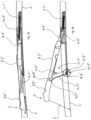
- the wind deflector arm 7, 7' is shown in respectively the retracted position and in the extended position.
- the wind deflector assembly is pushed downward into the retracted position by the panel 4 (only shown in Fig. 1 ) when panel 4 is being closed.
- the panel 4 comprises slide pads or other means to slidably push down the wind deflector assembly.
- the wind deflector arms 7, 7' are engaged by the panel 4 when the panel 4 is being closed.
- the elongated member 6 is pushed down to below the opening 1 in the roof of the vehicle.
- the biasing device 12, 12' is compressed fully in this position and biases the wind deflector arm in a vertical upward direction.
- the biasing device comprises first and second legs 13, 13'; 14, 14', which are integrally connected to each other at first ends 15, 15' of the first and second legs 13, 13' and 14, 14'. Nevertheless in this retracted position the wind deflector arms 7, 7' and the rest of the wind deflector assembly are kept in the retracted position by means of the panel 4.
- the pins in the slidable hinges 10, 10' at the second end 9, 9' of the wind deflector arms 7, 7' are now positioned substantially at the forward area of slotted hole.
- the spring 11, 11' is now biasing the second end 9, 9' of the wind deflector arm 7, 7' in a longitudinal direction to the rear and is extended towards its maximum length.
- the wind deflector assembly gradually moves in a substantially vertical direction towards the extended position.
- This upward movement is caused by the biasing force of the biasing device 12, 12'.
- This biasing force is mainly caused by the bending of the biasing device in the neighbourhood of the ends 15, 15' of the first and second legs 13, 13'and 14, 14', but also deformation of the legs themselves may cause the biasing force.
- the convex part 17, 17' of the first leg 13, 13' of the biasing device 12, 12' is pivotally engaged with a concave sliding bearing 18, 18' connected to the stationary part 3.
- the concave sliding bearing 18, 18' has a surface large enough to accommodate the full circumvention of the convex part 17, 17' of the first leg 13, 13' in both retracted and extended position of the wind deflector assembly.
- the second leg 14, 14' of the biasing device 12, 12' is clamped inside the wind deflector arm (not shown) by means of a click fixing or by means of a positive fixing such as a by means of a screw or by means of a supporting bracket and a screw in order to fix the second leg 14, 14' with respect to the wind deflector arm 7, 7.
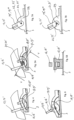
- the convex part 17, 17' of the first leg 13, 13' engaging in the concave sliding bearing 18, 18' is shown in more detail.
- the convex part 17, 17' may be a bend part of the first leg 13, 13' of the biasing device 12, 12'.
- the connection of the first leg 13, 13' and the convex part 17, 17' shows that the convex part 17, 17' is open at the rear, seen in a longitudinal direction. It is conceivable that the convex part 17, 17' is open at the front.
- a safety catch 20, 20' is shown, whereby the safety catch 20, 20' may be a pin attached like a bridge to the stationary part 3 and whereby the convex part 17, 17' at the second end 16, 16' of the first leg 13, 13' is circumventing the pin of the safety catch 20, 20' substantially completely.
- the convex part 17, 17' does not touch the pin of the safety catch 20, 20' in normal operation. Only when in case of exceptional circumstances such as in a crash situation with the vehicle, the convex part 17, 17' is lifted from the sliding bearing 18, 18', and the pin of the safety catch 20, 20' will hold the convex part 17, 17' as a safety measure.
- Fig. 6, 7A and 7B other embodiments are shown for the second end 16, 16' of the first leg 13, 13' of the biasing device 12, 12'.
- the second end 16, 16' comprises a separate part 19, 19', which is a plastic injection moulded convex shaped part, moulded to the second end 16, 16' of the first leg 13, 13'.
- this separate part 19, 19' is a solid part made of thermoplastic material or comprises a hole in the centre of rotation, such that this separate part 19, 19' is made suitable to be functionally combined with a safety catch 20, 20' such as is described before.
- FIG. 7A a fixed hinge construction is shown whereby a separate part 19", 19"' is attached to the first legs 13, 13' end.
- This plastic separate part 19", 19"' comprises a hole 22, 22' through which a pin 21, 21' is placed, which pin 21, 21' is attached to a hinge block 29 attached to the stationary part 3.
- pin 21, 21' and hole 22, 22' are interchanged, in that the pin 21, 21' is attached to the plastic part and the hole 22, 22' is formed in the hinge block 29 on the stationary part 3.
- a similar hinge construction is shown in fig. 7B , although here a slotted hole 22, 22' in the plastic moulded part 19, 19' is formed such that an easy assembly of the wind deflector assembly to the stationary part 3 is guaranteed.
- figs. 8A and 8B the height adjusting device 28, 28' is shown.
- Fig. 8A an upper position of the wind deflector assembly is shown whereby the elongated member 6 is positioned in its highest position.
- the end stop 24, 24' is in engagement with the auxiliary part 23, 23' on the wind deflector arm 7, 7'.
- the end stop 24, 24' is an adjustable part which is slidably engaged in a longitudinal channel 25, 25' formed in the guide which is part of the stationary part 3.
- the end stop 24, 24' is driven by the flexible drive cable 26, 26', which in turn is driven by an electric motor device 27 (see Fig. 2 ).
- the end stop 24, 24' is moved forward by the driveline of the drive cable 26, 26' and motor device 27.
- the pin of the slidable hinges 10, 10' is moved in forward direction by a distance X to a position substantially in the forward area of the slotted hole of the slidable hinge 10, 10'.
- the spring 11, 11' is extended and the wind deflector arm 7, 7' has moved in forward direction by said distance X, but also has been lowered a certain amount of height Y at the position of the elongated member 6.
- the elongated member 6 is now placed in a lower position which changes the aerodynamic surface of the wind deflector member 5 and therewith of the wind deflector assembly.
Landscapes
- Engineering & Computer Science (AREA)
- Mechanical Engineering (AREA)
- Body Structure For Vehicles (AREA)
- Air-Flow Control Members (AREA)
Claims (10)
- Ensemble déflecteur d'air destiné à être utilisé en face d'une ouverture de toit (1) d'une construction de toit ouvert (2) pour un véhicule, la construction de toit ouvert (2) comprenant une partie stationnaire (3) et un panneau (4) apte à fermer l'ouverture de toit (1) et à l'ouvrir au moins partiellement,
dans lequel l'ensemble déflecteur d'air est apte à se déplacer entre une position rétractée sous l'ouverture de toit (1) et une position étendue au-dessus de l'ouverture de toit (1) et comprend :un élément déflecteur d'air (5) qui s'étend dans une direction transversale du véhicule et qui est relié à une extrémité supérieure à un élément allongé (6) et à une extrémité inférieure opposée à la partie stationnaire (3), une paire de bras de déflecteur d'air (7, 7') reliés chacun à une première extrémité (8, 8') à une des extrémités opposées de l'élément allongé (6) et à une deuxième extrémité (9, 9') à la partie stationnaire (3) à l'aide d'une articulation coulissante (10, 10'),dans lequel l'ensemble déflecteur d'air est incliné au moyen d'un ressort (11, 11') dans une direction longitudinale vers l'arrière, ledit ressort (11, 11') étant relié à la deuxième extrémité (9, 9') de chaque bras de déflecteur d'air (5, 5'),dans lequel un dispositif d'inclinaison (12, 12') engage chaque bras de déflecteur d'air (7, 7') et pousse le bras de déflecteur d'air (7, 7') vers la position étendue,dans lequel le dispositif d'inclinaison (12, 12') comprend des première et deuxième branches (13, 13' ; 14, 14') reliées d'un seul tenant l'une à l'autre aux premières extrémités (15, 15') des première et deuxième branches (13, 13' ; 14, 14'),la première branche (13, 13') s'étendant entre le bras de déflecteur d'air (7, 7') et la partie stationnaire (3) de sorte à pousser le bras de déflecteur d'air (7, 7') vers la position étendue en coopération avec la deuxième branche, etdans lequel la deuxième branche (14, 14') du dispositif d'inclinaison (12, 12') est engagée avec une partie du bras de déflecteur d'air (7, 7') et s'étend sensiblement le long au moins de celle-ci, dans lequel une deuxième extrémité (16, 16') de la première branche (13, 13') est seulement reliée de manière pivotante par rapport à la partie stationnaire (3),dans lequel la première branche (13, 13') est la seule connexion d'inclinaison du dispositif d'inclinaison (12, 12') s'étendant entre la partie stationnaire (3) et le bras de déflecteur du vent (7, 7') de telle manière que la force pour pousser l'ensemble déflecteur d'air vers la position étendue soit seulement formée par la première branche (13, 13'). - Ensemble déflecteur d'air selon la revendication 1, dans lequel la première branche (13, 13') à la deuxième extrémité (16, 16') comprend une partie convexe (17, 17') qui forme une partie de la connexion pivotante avec la partie stationnaire (3).
- Ensemble déflecteur d'air selon la revendication 2, dans lequel ladite partie convexe (17, 17') de la première branche (13, 13') avec son côté convexe engage d'une manière rotative un palier coulissant concave (18, 18') attaché à la partie stationnaire (3).
- Ensemble déflecteur d'air selon la revendication 3, dans lequel le palier coulissant concave (18, 18') est réalisé en un matériau thermoplastique et est en particulier fabriqué en matériau PET ou en un autre matériau de la même classe de matériaux.
- Ensemble déflecteur d'air selon la revendication 1, dans lequel la première branche (13, 13') est équipée à sa deuxième extrémité (16, 16') d'une partie séparée (19, 19') ayant une forme convexe.
- Ensemble déflecteur d'air selon la revendication 3, dans lequel le palier coulissant concave (18, 18') est équipé d'un cran de sécurité (20, 20') apte à contenir la première branche (13, 13') dans un tel cas lorsque la partie convexe (17, 17') perd le contact avec le palier coulissant concave (18, 18').
- Ensemble déflecteur d'air selon la revendication 1, dans lequel la connexion pivotante entre la première branche (13, 13') et la partie stationnaire (3) est formée par une construction d'articulation.
- Ensemble déflecteur d'air selon la revendication 1, dans lequel l'ensemble déflecteur d'air est équipé d'un dispositif d'ajustement de hauteur (28), ledit dispositif d'ajustement de hauteur (28) comprenant une partie auxiliaire (23, 23') s'étendant depuis le bras de déflecteur d'air (7, 7') dans une direction latérale près de la connexion mobile du bras de déflecteur d'air (7, 7') avec la partie stationnaire (3) et une butée d'extrémité mobile (24, 24') prévue engagée de manière coulissante dans un canal longitudinal (25, 25') dans la partie stationnaire (3), ladite butée d'extrémité (24, 24') étant apte à se déplacer dans une direction sensiblement longitudinale et dans lequel la butée d'extrémité mobile (24, 24') est en engagement avec la partie auxiliaire (23, 23') lorsque l'élément déflecteur d'air (5) est dans une position au moins étendue.
- Ensemble déflecteur d'air selon la revendication 8, dans lequel la butée d'extrémité (24, 24') est en engagement avec la partie auxiliaire (23, 23') lorsque l'ensemble déflecteur d'air est dans sa position étendue et dans lequel l'ensemble déflecteur d'air est déplacé dans une position étendue inférieure par le mouvement de la butée d'extrémité (24, 24') contre la partie auxiliaire (23, 23') dans une direction vers l'avant sensiblement longitudinale de sorte à abaisser la hauteur verticale de l'ensemble déflecteur d'air.
- Ensemble déflecteur d'air selon la revendication 9, dans lequel la butée d'extrémité (24, 24') est agencée de manière coulissante dans un canal longitudinal (25, 25') dans la partie stationnaire (3) et dans lequel la butée d'extrémité (24, 24') est entraînée par un câble flexible (26, 26') connecté à un dispositif à moteur (27).
Priority Applications (3)
| Application Number | Priority Date | Filing Date | Title |
|---|---|---|---|
| EP19197710.7A EP3795397B1 (fr) | 2019-09-17 | 2019-09-17 | Ensemble déflecteur d'air |
| US17/022,632 US11396223B2 (en) | 2019-09-17 | 2020-09-16 | Wind deflector assembly |
| CN202010977864.4A CN112519549A (zh) | 2019-09-17 | 2020-09-17 | 挡风板组件 |
Applications Claiming Priority (1)
| Application Number | Priority Date | Filing Date | Title |
|---|---|---|---|
| EP19197710.7A EP3795397B1 (fr) | 2019-09-17 | 2019-09-17 | Ensemble déflecteur d'air |
Publications (2)
| Publication Number | Publication Date |
|---|---|
| EP3795397A1 EP3795397A1 (fr) | 2021-03-24 |
| EP3795397B1 true EP3795397B1 (fr) | 2023-11-01 |
Family
ID=67988911
Family Applications (1)
| Application Number | Title | Priority Date | Filing Date |
|---|---|---|---|
| EP19197710.7A Active EP3795397B1 (fr) | 2019-09-17 | 2019-09-17 | Ensemble déflecteur d'air |
Country Status (3)
| Country | Link |
|---|---|
| US (1) | US11396223B2 (fr) |
| EP (1) | EP3795397B1 (fr) |
| CN (1) | CN112519549A (fr) |
Families Citing this family (1)
| Publication number | Priority date | Publication date | Assignee | Title |
|---|---|---|---|---|
| DE202022104414U1 (de) * | 2022-08-03 | 2022-10-25 | Roof Systems Germany Gmbh | Windabweiser für ein Fahrzeug-Schiebedachsystem |
Family Cites Families (21)
| Publication number | Priority date | Publication date | Assignee | Title |
|---|---|---|---|---|
| BE628101A (fr) | 1962-03-13 | |||
| DE3137191A1 (de) | 1981-09-18 | 1983-03-31 | Rockwell Golde Gmbh, 6000 Frankfurt | Windabweisvorrichtung an einem kraftfahrzeugdach |
| JPS5889419A (ja) | 1981-11-24 | 1983-05-27 | Mazda Motor Corp | 自動車のル−フ開口装置 |
| JPS6071327A (ja) | 1983-09-29 | 1985-04-23 | Johnan Seisakusho Co Ltd | 自動車のサンルーフ開閉装置 |
| JPS6078826A (ja) | 1983-10-06 | 1985-05-04 | Toyota Motor Corp | サンル−フ用デフレクタ |
| JPS61169319A (ja) | 1985-01-23 | 1986-07-31 | Mazda Motor Corp | サンル−フのデイフレクタ−昇降装置 |
| IT8553228V0 (it) | 1985-04-15 | 1985-04-15 | Gilardini Spa | Tetto apribile per veicoli |
| DE3908750C1 (fr) | 1989-03-17 | 1990-06-07 | Rockwell Golde Gmbh, 6000 Frankfurt, De | |
| DE19505006C1 (de) | 1995-02-15 | 1996-04-04 | Webasto Karosseriesysteme | Fahrzeugdach mit zwei Deckelelementen |
| DE19549200A1 (de) | 1995-12-30 | 1997-07-03 | Webasto Karosseriesysteme | Windleitelement für ein Fahrzeugdach |
| DE69821452T2 (de) * | 1997-11-07 | 2004-12-23 | Inalfa Roof Systems Group B.V. | Konstruktion eines öffnungsfähigen Fahrzeugdaches |
| DE102005033431B4 (de) * | 2005-07-18 | 2008-06-19 | Webasto Ag | Vorrichtung zur Beeinflussung einer Luftströmung an einem öffnungsfähigen Fahrzeugdach |
| EP1844969B1 (fr) | 2006-04-06 | 2010-06-09 | ArvinMeritor GmbH | Mécanisme pour le déflecteur de vent d'un toit coulissant de véhicule |
| DE102009009465A1 (de) | 2009-02-18 | 2010-08-26 | Magna Car Top Systems Gmbh | Windabweisereinrichtung und Fahrzeug |
| DE102011103527A1 (de) | 2011-06-07 | 2012-12-13 | Roof Systems Germany Gmbh | Schiebedachsystem |
| US8459729B1 (en) * | 2012-03-16 | 2013-06-11 | Webasto Roof Systems Inc. | Wind deflector assemblies for an opening of a vehicle roof |
| DE102014004992B3 (de) | 2014-04-02 | 2015-07-02 | Webasto SE | Windabweiser eines öffnungsfähigen Fahrzeugdaches |
| KR101585469B1 (ko) | 2014-09-15 | 2016-01-14 | 현대자동차주식회사 | 선루프 디플렉터 지지구조 |
| EP3342612B1 (fr) | 2016-12-29 | 2020-08-19 | Inalfa Roof Systems Group B.V. | Ensemble déflecteur d'air |
| CN206734037U (zh) * | 2017-03-09 | 2017-12-12 | 上海恩坦华汽车部件有限公司 | 车用扰流装置及天窗 |
| CN208812958U (zh) * | 2018-08-29 | 2019-05-03 | 英纳法企业管理(上海)有限公司 | 用于汽车天窗挡风网的支撑机构及汽车天窗挡风网结构 |
-
2019
- 2019-09-17 EP EP19197710.7A patent/EP3795397B1/fr active Active
-
2020
- 2020-09-16 US US17/022,632 patent/US11396223B2/en active Active
- 2020-09-17 CN CN202010977864.4A patent/CN112519549A/zh active Pending
Also Published As
| Publication number | Publication date |
|---|---|
| EP3795397A1 (fr) | 2021-03-24 |
| US11396223B2 (en) | 2022-07-26 |
| CN112519549A (zh) | 2021-03-19 |
| US20210078392A1 (en) | 2021-03-18 |
Similar Documents
| Publication | Publication Date | Title |
|---|---|---|
| CA1045653A (fr) | Toiture coulissante pour pavillon d'automobile | |
| EP2657054A1 (fr) | Appareil de toit ouvrant | |
| CN102300732B (zh) | 用于车辆的车顶组件 | |
| KR20070029819A (ko) | 바람 전향 장치 | |
| US6325453B1 (en) | Open roof construction for a vehicle | |
| US9266415B1 (en) | Roof assembly for a vehicle | |
| EP3795397B1 (fr) | Ensemble déflecteur d'air | |
| JP3832948B2 (ja) | サンルーフのデフレクタ装置 | |
| JPH0143932Y2 (fr) | ||
| US20070138841A1 (en) | Sliding roof system for a motor vehicle | |
| EP2275297B1 (fr) | Ensemble de toiture pour véhicule, et procédé de déplacement d'un panneau de fermeture et déflecteur d'air d'un ensemble de toiture | |
| US4971387A (en) | Air guide device for an automobile roof | |
| NL1009071C2 (nl) | Open-dakconstructie voor een voertuig. | |
| US6164717A (en) | Wind deflector for a vehicle sunroof | |
| US8333426B2 (en) | Rise up panoramic roof for a vehicle | |
| JP4105637B2 (ja) | 車両用の屋根組立体 | |
| EP2868504B1 (fr) | Ensemble de fermeture de toit et agencement de déflecteur de vent | |
| EP2105333B1 (fr) | Ensemble de toit pour véhicule et son procédé de fonctionnement | |
| EP1070615B2 (fr) | Construction d'un toit ouvrant pour véhicule | |
| US10507713B2 (en) | Wind deflector assembly for vehicle roof | |
| US6019417A (en) | Articulated device for attaching a top storage well cover | |
| JP3657570B2 (ja) | サンルーフ装置のディフレクタ | |
| US7000981B2 (en) | Collapsible wind deflector for a vehicle roof | |
| EP1625960B1 (fr) | Assemblage d'éléments de toit pour un véhicule | |
| JP7394264B2 (ja) | サンルーフ装置のディフレクタ構造 |
Legal Events
| Date | Code | Title | Description |
|---|---|---|---|
| PUAI | Public reference made under article 153(3) epc to a published international application that has entered the european phase |
Free format text: ORIGINAL CODE: 0009012 |
|
| STAA | Information on the status of an ep patent application or granted ep patent |
Free format text: STATUS: THE APPLICATION HAS BEEN PUBLISHED |
|
| AK | Designated contracting states |
Kind code of ref document: A1 Designated state(s): AL AT BE BG CH CY CZ DE DK EE ES FI FR GB GR HR HU IE IS IT LI LT LU LV MC MK MT NL NO PL PT RO RS SE SI SK SM TR |
|
| AX | Request for extension of the european patent |
Extension state: BA ME |
|
| STAA | Information on the status of an ep patent application or granted ep patent |
Free format text: STATUS: REQUEST FOR EXAMINATION WAS MADE |
|
| 17P | Request for examination filed |
Effective date: 20210923 |
|
| RBV | Designated contracting states (corrected) |
Designated state(s): AL AT BE BG CH CY CZ DE DK EE ES FI FR GB GR HR HU IE IS IT LI LT LU LV MC MK MT NL NO PL PT RO RS SE SI SK SM TR |
|
| STAA | Information on the status of an ep patent application or granted ep patent |
Free format text: STATUS: EXAMINATION IS IN PROGRESS |
|
| 17Q | First examination report despatched |
Effective date: 20220930 |
|
| GRAP | Despatch of communication of intention to grant a patent |
Free format text: ORIGINAL CODE: EPIDOSNIGR1 |
|
| STAA | Information on the status of an ep patent application or granted ep patent |
Free format text: STATUS: GRANT OF PATENT IS INTENDED |
|
| INTG | Intention to grant announced |
Effective date: 20230607 |
|
| GRAS | Grant fee paid |
Free format text: ORIGINAL CODE: EPIDOSNIGR3 |
|
| GRAA | (expected) grant |
Free format text: ORIGINAL CODE: 0009210 |
|
| STAA | Information on the status of an ep patent application or granted ep patent |
Free format text: STATUS: THE PATENT HAS BEEN GRANTED |
|
| AK | Designated contracting states |
Kind code of ref document: B1 Designated state(s): AL AT BE BG CH CY CZ DE DK EE ES FI FR GB GR HR HU IE IS IT LI LT LU LV MC MK MT NL NO PL PT RO RS SE SI SK SM TR |
|
| REG | Reference to a national code |
Ref country code: GB Ref legal event code: FG4D |
|
| REG | Reference to a national code |
Ref country code: CH Ref legal event code: EP |
|
| REG | Reference to a national code |
Ref country code: IE Ref legal event code: FG4D |
|
| REG | Reference to a national code |
Ref country code: DE Ref legal event code: R096 Ref document number: 602019040456 Country of ref document: DE |
|
| REG | Reference to a national code |
Ref country code: LT Ref legal event code: MG9D |
|
| REG | Reference to a national code |
Ref country code: NL Ref legal event code: MP Effective date: 20231101 |
|
| PG25 | Lapsed in a contracting state [announced via postgrant information from national office to epo] |
Ref country code: GR Free format text: LAPSE BECAUSE OF FAILURE TO SUBMIT A TRANSLATION OF THE DESCRIPTION OR TO PAY THE FEE WITHIN THE PRESCRIBED TIME-LIMIT Effective date: 20240202 |
|
| PG25 | Lapsed in a contracting state [announced via postgrant information from national office to epo] |
Ref country code: IS Free format text: LAPSE BECAUSE OF FAILURE TO SUBMIT A TRANSLATION OF THE DESCRIPTION OR TO PAY THE FEE WITHIN THE PRESCRIBED TIME-LIMIT Effective date: 20240301 |
|
| PG25 | Lapsed in a contracting state [announced via postgrant information from national office to epo] |
Ref country code: LT Free format text: LAPSE BECAUSE OF FAILURE TO SUBMIT A TRANSLATION OF THE DESCRIPTION OR TO PAY THE FEE WITHIN THE PRESCRIBED TIME-LIMIT Effective date: 20231101 |
|
| REG | Reference to a national code |
Ref country code: AT Ref legal event code: MK05 Ref document number: 1626831 Country of ref document: AT Kind code of ref document: T Effective date: 20231101 |
|
| PG25 | Lapsed in a contracting state [announced via postgrant information from national office to epo] |
Ref country code: NL Free format text: LAPSE BECAUSE OF FAILURE TO SUBMIT A TRANSLATION OF THE DESCRIPTION OR TO PAY THE FEE WITHIN THE PRESCRIBED TIME-LIMIT Effective date: 20231101 |
|
| PG25 | Lapsed in a contracting state [announced via postgrant information from national office to epo] |
Ref country code: AT Free format text: LAPSE BECAUSE OF FAILURE TO SUBMIT A TRANSLATION OF THE DESCRIPTION OR TO PAY THE FEE WITHIN THE PRESCRIBED TIME-LIMIT Effective date: 20231101 |
|
| PG25 | Lapsed in a contracting state [announced via postgrant information from national office to epo] |
Ref country code: ES Free format text: LAPSE BECAUSE OF FAILURE TO SUBMIT A TRANSLATION OF THE DESCRIPTION OR TO PAY THE FEE WITHIN THE PRESCRIBED TIME-LIMIT Effective date: 20231101 |
|
| PG25 | Lapsed in a contracting state [announced via postgrant information from national office to epo] |
Ref country code: NL Free format text: LAPSE BECAUSE OF FAILURE TO SUBMIT A TRANSLATION OF THE DESCRIPTION OR TO PAY THE FEE WITHIN THE PRESCRIBED TIME-LIMIT Effective date: 20231101 Ref country code: LT Free format text: LAPSE BECAUSE OF FAILURE TO SUBMIT A TRANSLATION OF THE DESCRIPTION OR TO PAY THE FEE WITHIN THE PRESCRIBED TIME-LIMIT Effective date: 20231101 Ref country code: IS Free format text: LAPSE BECAUSE OF FAILURE TO SUBMIT A TRANSLATION OF THE DESCRIPTION OR TO PAY THE FEE WITHIN THE PRESCRIBED TIME-LIMIT Effective date: 20240301 Ref country code: GR Free format text: LAPSE BECAUSE OF FAILURE TO SUBMIT A TRANSLATION OF THE DESCRIPTION OR TO PAY THE FEE WITHIN THE PRESCRIBED TIME-LIMIT Effective date: 20240202 Ref country code: ES Free format text: LAPSE BECAUSE OF FAILURE TO SUBMIT A TRANSLATION OF THE DESCRIPTION OR TO PAY THE FEE WITHIN THE PRESCRIBED TIME-LIMIT Effective date: 20231101 Ref country code: BG Free format text: LAPSE BECAUSE OF FAILURE TO SUBMIT A TRANSLATION OF THE DESCRIPTION OR TO PAY THE FEE WITHIN THE PRESCRIBED TIME-LIMIT Effective date: 20240201 Ref country code: AT Free format text: LAPSE BECAUSE OF FAILURE TO SUBMIT A TRANSLATION OF THE DESCRIPTION OR TO PAY THE FEE WITHIN THE PRESCRIBED TIME-LIMIT Effective date: 20231101 Ref country code: PT Free format text: LAPSE BECAUSE OF FAILURE TO SUBMIT A TRANSLATION OF THE DESCRIPTION OR TO PAY THE FEE WITHIN THE PRESCRIBED TIME-LIMIT Effective date: 20240301 |