EP3793407B1 - Schiebe-schwenkmechanik einer ablage eines möbels oder haushaltsgerätes und möbel oder haushaltsgerät - Google Patents
Schiebe-schwenkmechanik einer ablage eines möbels oder haushaltsgerätes und möbel oder haushaltsgerät Download PDFInfo
- Publication number
- EP3793407B1 EP3793407B1 EP19722119.5A EP19722119A EP3793407B1 EP 3793407 B1 EP3793407 B1 EP 3793407B1 EP 19722119 A EP19722119 A EP 19722119A EP 3793407 B1 EP3793407 B1 EP 3793407B1
- Authority
- EP
- European Patent Office
- Prior art keywords
- furniture
- coupling unit
- shelf
- household appliance
- piece
- Prior art date
- Legal status (The legal status is an assumption and is not a legal conclusion. Google has not performed a legal analysis and makes no representation as to the accuracy of the status listed.)
- Active
Links
- 230000007246 mechanism Effects 0.000 title claims description 81
- 230000008878 coupling Effects 0.000 claims description 124
- 238000010168 coupling process Methods 0.000 claims description 124
- 238000005859 coupling reaction Methods 0.000 claims description 124
- 238000005096 rolling process Methods 0.000 claims description 9
- 238000010411 cooking Methods 0.000 claims description 5
- 238000005406 washing Methods 0.000 claims description 3
- 238000001816 cooling Methods 0.000 claims 2
- 238000000418 atomic force spectrum Methods 0.000 claims 1
- 239000011324 bead Substances 0.000 description 2
- 230000008901 benefit Effects 0.000 description 2
- 230000008859 change Effects 0.000 description 2
- 238000000034 method Methods 0.000 description 2
- 230000008569 process Effects 0.000 description 2
- 230000007704 transition Effects 0.000 description 2
- 230000001419 dependent effect Effects 0.000 description 1
- 210000003205 muscle Anatomy 0.000 description 1
Images


Classifications
-
- A—HUMAN NECESSITIES
- A47—FURNITURE; DOMESTIC ARTICLES OR APPLIANCES; COFFEE MILLS; SPICE MILLS; SUCTION CLEANERS IN GENERAL
- A47B—TABLES; DESKS; OFFICE FURNITURE; CABINETS; DRAWERS; GENERAL DETAILS OF FURNITURE
- A47B88/00—Drawers for tables, cabinets or like furniture; Guides for drawers
- A47B88/40—Sliding drawers; Slides or guides therefor
- A47B88/407—Adjustably or detachably mounted drawers
-
- A—HUMAN NECESSITIES
- A47—FURNITURE; DOMESTIC ARTICLES OR APPLIANCES; COFFEE MILLS; SPICE MILLS; SUCTION CLEANERS IN GENERAL
- A47B—TABLES; DESKS; OFFICE FURNITURE; CABINETS; DRAWERS; GENERAL DETAILS OF FURNITURE
- A47B46/00—Cabinets, racks or shelf units, having one or more surfaces adapted to be brought into position for use by extending or pivoting
- A47B46/005—Cabinets, racks or shelf units, having one or more surfaces adapted to be brought into position for use by extending or pivoting by displacement in a vertical plane; by rotating about a horizontal axis
-
- A—HUMAN NECESSITIES
- A47—FURNITURE; DOMESTIC ARTICLES OR APPLIANCES; COFFEE MILLS; SPICE MILLS; SUCTION CLEANERS IN GENERAL
- A47B—TABLES; DESKS; OFFICE FURNITURE; CABINETS; DRAWERS; GENERAL DETAILS OF FURNITURE
- A47B88/00—Drawers for tables, cabinets or like furniture; Guides for drawers
- A47B88/40—Sliding drawers; Slides or guides therefor
- A47B88/437—Rollers for slides or guides
-
- A—HUMAN NECESSITIES
- A47—FURNITURE; DOMESTIC ARTICLES OR APPLIANCES; COFFEE MILLS; SPICE MILLS; SUCTION CLEANERS IN GENERAL
- A47L—DOMESTIC WASHING OR CLEANING; SUCTION CLEANERS IN GENERAL
- A47L15/00—Washing or rinsing machines for crockery or tableware
- A47L15/42—Details
- A47L15/50—Racks ; Baskets
- A47L15/506—Arrangements for lifting racks for loading or unloading purposes
-
- A—HUMAN NECESSITIES
- A47—FURNITURE; DOMESTIC ARTICLES OR APPLIANCES; COFFEE MILLS; SPICE MILLS; SUCTION CLEANERS IN GENERAL
- A47L—DOMESTIC WASHING OR CLEANING; SUCTION CLEANERS IN GENERAL
- A47L15/00—Washing or rinsing machines for crockery or tableware
- A47L15/42—Details
- A47L15/50—Racks ; Baskets
- A47L15/507—Arrangements for extracting racks, e.g. roller supports
-
- F—MECHANICAL ENGINEERING; LIGHTING; HEATING; WEAPONS; BLASTING
- F24—HEATING; RANGES; VENTILATING
- F24C—DOMESTIC STOVES OR RANGES ; DETAILS OF DOMESTIC STOVES OR RANGES, OF GENERAL APPLICATION
- F24C15/00—Details
- F24C15/16—Shelves, racks or trays inside ovens; Supports therefor
-
- F—MECHANICAL ENGINEERING; LIGHTING; HEATING; WEAPONS; BLASTING
- F25—REFRIGERATION OR COOLING; COMBINED HEATING AND REFRIGERATION SYSTEMS; HEAT PUMP SYSTEMS; MANUFACTURE OR STORAGE OF ICE; LIQUEFACTION SOLIDIFICATION OF GASES
- F25D—REFRIGERATORS; COLD ROOMS; ICE-BOXES; COOLING OR FREEZING APPARATUS NOT OTHERWISE PROVIDED FOR
- F25D25/00—Charging, supporting, and discharging the articles to be cooled
- F25D25/02—Charging, supporting, and discharging the articles to be cooled by shelves
- F25D25/024—Slidable shelves
- F25D25/025—Drawers
-
- A—HUMAN NECESSITIES
- A47—FURNITURE; DOMESTIC ARTICLES OR APPLIANCES; COFFEE MILLS; SPICE MILLS; SUCTION CLEANERS IN GENERAL
- A47B—TABLES; DESKS; OFFICE FURNITURE; CABINETS; DRAWERS; GENERAL DETAILS OF FURNITURE
- A47B88/00—Drawers for tables, cabinets or like furniture; Guides for drawers
- A47B88/90—Constructional details of drawers
- A47B2088/901—Drawers having a lifting mechanism
-
- A—HUMAN NECESSITIES
- A47—FURNITURE; DOMESTIC ARTICLES OR APPLIANCES; COFFEE MILLS; SPICE MILLS; SUCTION CLEANERS IN GENERAL
- A47B—TABLES; DESKS; OFFICE FURNITURE; CABINETS; DRAWERS; GENERAL DETAILS OF FURNITURE
- A47B2210/00—General construction of drawers, guides and guide devices
- A47B2210/0002—Guide construction for drawers
- A47B2210/0029—Guide bearing means
- A47B2210/0037—Rollers
-
- A—HUMAN NECESSITIES
- A47—FURNITURE; DOMESTIC ARTICLES OR APPLIANCES; COFFEE MILLS; SPICE MILLS; SUCTION CLEANERS IN GENERAL
- A47B—TABLES; DESKS; OFFICE FURNITURE; CABINETS; DRAWERS; GENERAL DETAILS OF FURNITURE
- A47B2210/00—General construction of drawers, guides and guide devices
- A47B2210/0002—Guide construction for drawers
- A47B2210/0051—Guide position
- A47B2210/0056—Guide located at the bottom of the drawer
-
- A—HUMAN NECESSITIES
- A47—FURNITURE; DOMESTIC ARTICLES OR APPLIANCES; COFFEE MILLS; SPICE MILLS; SUCTION CLEANERS IN GENERAL
- A47B—TABLES; DESKS; OFFICE FURNITURE; CABINETS; DRAWERS; GENERAL DETAILS OF FURNITURE
- A47B2210/00—General construction of drawers, guides and guide devices
- A47B2210/04—Metal wire drawers
-
- A—HUMAN NECESSITIES
- A47—FURNITURE; DOMESTIC ARTICLES OR APPLIANCES; COFFEE MILLS; SPICE MILLS; SUCTION CLEANERS IN GENERAL
- A47B—TABLES; DESKS; OFFICE FURNITURE; CABINETS; DRAWERS; GENERAL DETAILS OF FURNITURE
- A47B2210/00—General construction of drawers, guides and guide devices
- A47B2210/17—Drawers used in connection with household appliances
Definitions
- the present invention relates to a piece of furniture or a household appliance with a shelf fixed by means of a sliding/pivoting mechanism according to the preamble of claims 1 and 2.
- Sliding and pivoting mechanisms of this type are used, for example, in dishwashers for raising and lowering a lower shelf, in particular a crockery basket, in order to enable loading and unloading of the shelf in an upright position of a user, which relieves the back muscles and spine.
- a generic sliding-pivoting mechanism is, for example, from DE 10 2014 114 285 A1 known.
- the sliding and pivoting mechanism described there essentially has a pull-out guide and a pivoting mechanism with two pivoting levers, which supports the raising and lowering of the shelf with the aid of a tension spring.
- the sliding and pivoting mechanism is actuated by the user using a lever unit that supports the raising and lowering of the pivoting mechanism. With this lever unit, it is already possible to raise and lower the shelf more easily and with less effort.
- the object of the present invention is to further develop the sliding/pivoting mechanism in such a way that the actuating forces to be applied are further reduced.
- the sliding and pivoting mechanism according to the invention has at least two pivoting arms of a pivoting mechanism which are arranged on at least one of the side walls of the body with a first end parallel to the plane of the side walls and are rotatably fixed and spaced parallel to one another.
- a guide rail of a sliding mechanism is pivotably fixed parallel to the plane of the side walls such that the guide rail can be pivoted from a lower position inside the body to a raised, upper position at least partially outside the body.
- a running rail is linearly displaceable relative to the guide rail.
- the shelf is attached to the running rail.
- the sliding pivoting mechanism also has a lever unit that supports raising and lowering of the pivoting mechanism and is pivotably fixed to the running rail parallel to the plane of the side walls.
- At least one coupling element of a first coupling unit is arranged on the lever unit in such a way that the coupling element can be coupled to at least one of the pivot arms by moving the running rail into a predetermined pivoting position with a correspondence element of the first coupling unit corresponding to the coupling element.
- the coupling element of the first coupling unit is designed as a sliding or rolling element, preferably as a sliding bolt or as a roller, which is used to control the sequence of the pivoting movement of the lever unit in a correspondence element that is arranged, in particular formed, on at least one of the pivoting arms and is designed as a link guide is manageable.
- the coupling element of the first coupling unit is designed as a slotted guide, in which a correspondence element arranged on at least one of the pivot arms and designed as a roller can be guided to control the sequence of the pivoting movement of the lever unit.
- lever unit integrated into the sliding/pivoting mechanism in this way, it is possible to easily couple the lever unit to at least one pivoting lever by simply advancing the running rail and the corresponding lever unit into the pivoting or lifting position.
- This solution also further reduces the actuating forces required to lift the tray, since the first coupling unit allows the ratio of the lifting path to the actuating path to be adjusted individually for the application.
- the design of the components of the coupling unit as a sliding or rolling element and link guide enable a simple coupling of the respective components without having to use a complex coupling.
- the coupling and also the decoupling can be carried out without an additional actuating element or a special unlocking movement and thus enable a smooth sequence of the coupling or decoupling.
- At least one coupling element of a second coupling unit is arranged on the running rail or the shelf in such a way that the coupling element can be coupled to at least one of the pivoting arms by moving the running rail into a predetermined pivoting position with a correspondence element of the second coupling unit that corresponds to the coupling element.
- the coupling element of the second coupling unit is designed as a sliding or rolling element, preferably as a sliding bolt or as a roller, which can be guided in a correspondence element arranged, in particular formed on, the at least one of the pivoting arms and designed as a link guide for sequence control of the pivoting movement of the pivoting mechanism .
- the link guide can also be formed in a separate element that is arranged on one of the swivel arms.
- the slotted guides of the first coupling unit and the second coupling unit are arranged, in particular formed, on at least one of the swivel arms.
- the slotted guide of the first coupling unit is arranged, in particular molded, on a first of the pivoting arms and the slotted guide of the second coupling unit on a second of the pivoting arms.
- the lever unit itself has at least one lever arm fixed with a first end on the running rail so that it can pivot parallel to the plane of the side walls and to which the coupling element or the corresponding element of the first coupling unit is fastened.
- At least one of the swivel arms, the pull-out guide, the first coupling unit and/or the lever unit are designed in such a way that a controlled sequence of the lever unit is ensured. In particular, this prevents the tray from being raised too early and the lever unit from moving too far beyond the end positions of the tray.
- At least one of the swivel arms, the pull-out guide, the first coupling unit and/or the lever unit has corresponding stop or guide areas.
- a correspondence element can also interact with a guide area.
- a link chain is attached pivotably to one end of the lever arm near a lever arm mount of the lever arm, at the end of which the lever arm is remote from the as Roller trained correspondence element of the first coupling unit is rotatably mounted.
- the movement of the actuating lever can be designed in such a way that the handle attached to one end of the lever arm is positioned when the lower shelf is in the raised state such that a cutlery shelf arranged above the upper shelf is at can still be pulled out when the lower shelf is raised.
- the articulated chain preferably has at least two chain links coupled to one another in a pivoting manner.
- the coupling element of the second coupling unit is designed as a sliding or rolling element arranged rotatably on at least one of the pivot arms, which can be guided in a correspondence element arranged, in particular molded on, on the lever arm holder of the lever arm and designed as a link guide for sequence control of the pivoting movement of the pivot mechanism is.
- At least a partial section of the connecting link guide of the first and second coupling unit is designed with an entry area.
- At least a partial section of the connecting link guide of the second coupling unit is part-circular designed, which ensures precise sequence control when raising and lowering the shelf.
- a section of the connecting link guide of the first coupling unit is designed as a dead center section.
- the shelf can be secured in a raised, upper end position in a simple manner, in particular without the need for locking the sliding/pivoting mechanism in this position.
- This means that a secured upper end position of the shelf is reached without an additional locking element and can be left again without an additional release element.
- a section of the connecting link guide of the first coupling unit has a pitch that is matched to an optimal course of the actuating force. In particular, this enables the shelf to be lifted with the user exerting almost the same amount of force.
- top, bottom, left, right, front, rear, etc. refer exclusively to the exemplary depiction and position of the slide and swivel mechanism, shelf, swivel arms, lever unit, pull-out guide and the like selected in the respective figures. These terms are not to be understood as limiting, i.e. these references can change due to different working positions or the mirror-symmetrical design or the like.
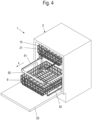
- FIG. 1 to 13 shows a first embodiment of a sliding swivel mechanism according to the invention, with which a lower shelf 9, here in the form of a crockery basket, can be moved from the interior or utility space 22 of a household appliance, here designed as a dishwasher 1, from an inserted lower position to a position pulled out of the utility space and upwardly pivoted loading and unloading can be raised.
- a lower shelf 9 here in the form of a crockery basket
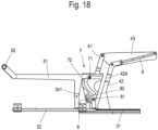
- FIGS 14 to 23 show an alternative second embodiment variant of such a sliding pivoting mechanism, in which a first pivoting lever 41 and a second pivoting lever 42 are not in a lowered initial position, as in the variant according to FIG Figures 1 to 13 aligned vertically, but inclined forward at an angle of about 20°.
- This angular orientation of the pivoted levers 41, 42 offers the advantage over the first embodiment variant that it enables a greater pull-out distance in the lower position without the shelf 9 protruding too far forward in the upper end position. This improves access to the shelf 9 in the lower, extended position, without the distance between the shelf 9 and the body 2 in the fully raised position differing from the position in the first embodiment variant.
- the angled orientation offers the advantage that higher objects can be placed in the shelf without colliding with the lever unit 5 due to the changed pivoting path.
- a middle rail between the guide rail 31 and the running rail 32 is conceivable, but not necessary.
- An additional middle rail can increase the stability and the pull-out distance of the drawer runner.
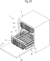
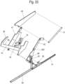
- FIGS. 24 to 33 show a third embodiment of a slide-pivoting mechanism according to the invention.
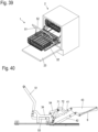
- FIGS. 34 to 45 show a fourth embodiment of a slide-pivoting mechanism according to the invention.
- an upper shelf 10 is arranged above it, which can be pulled out of the usable space 22 of the body 2 of the dishwasher 1 via a further pull-out guide (not shown here). .
- a shelf 9 or two shelves 9, 10 arranged in a piece of furniture or another household appliance for example a cooking appliance such as an oven or the like or a refrigerator.
- a sliding and pivoting mechanism is preferably arranged on each of the side walls 21 of the piece of furniture or household appliance in order to be able to adequately support a shelf 9 such as the crockery basket shown here.
- the pivoting mechanism 4 has, as shown in FIGS 2 , 15 , 25 and 35 shown, two on a side wall 21 with a first end parallel to the plane of the side walls 21 rotatably fixed and parallel spaced apart pivot arms 41, 42 on.
- the swivel arms 41, 42 are rotatably fixed to a side wall mount 43 via respective rotary joints 412, 422 on the side wall mount 43.
- the guide rail 31 of a respective pull-out guide 3 is fixed via swivel joints 411, 421.
- the second swivel arm 42 is preferably connected to the side wall mount 43 via a force accumulator 6, for example in the form of a helical spring or gas pressure spring, in such a way that the raising and/or lowering of the swivel mechanism 4 is supported by the force accumulator 6 by pivoting the second pivot arm 42.
- a force accumulator 6 for example in the form of a helical spring or gas pressure spring, in such a way that the raising and/or lowering of the swivel mechanism 4 is supported by the force accumulator 6 by pivoting the second pivot arm 42.
- the energy accumulator 6 can also have a damper.
- all design variants of the sliding/pivoting mechanism have a lever unit 5 that supports raising and lowering of the pivoting mechanism 4 and is pivotably fixed to the running rail 32 parallel to the plane of the side walls 21 .
- At least one coupling element of a first coupling unit 7 is arranged on lever unit 5 in such a way that the coupling element can be coupled to at least one of the pivot arms 41, 42 by moving the running rail 32 into a predetermined pivoting position with a correspondence element of the first coupling unit 7 that corresponds to the coupling element.
- All of the embodiment variants also have a second coupling unit 8, with at least one coupling element of this second coupling unit 8 being arranged on the running rail 32 or the shelf 9 in such a way that the coupling element can be connected to a correspondence element corresponding to the coupling element by moving the running rail 32 into a predetermined pivoting position at least one of the swivel arms 41, 42 can be coupled to the second coupling unit 8.
- each of the coupling units 7, 8 preferably has a roller 71, 81 and a link guide 72, 82, in which the respective roller 71, 81 can be guided.
- the main task of the slotted guide 82 is to prevent uncontrolled rail movement during pivoting.
- the slotted guide 72 can advantageously be designed in such a way that it has at least one sliding surface, in particular a raised surface, for guiding the lever arm 51 during the extension movement, so that the lever arm 51 is prevented from rubbing on the slotted guide 72 or on the pivot arms 41, 42 becomes.
- the at least one sliding surface 423 can also be arranged on one of the swivel arms 41, 42, as is exemplified in FIGS figures 26 and 33 is shown.
- the roller 81 of the second coupling unit 8 is fastened to the running rail 32 .
- the roller 81 is preferably attached to a roller bracket 35 that protrudes upwards in the direction of the side wall bracket 43 in a rear region of the roller rail 32 in the extension direction x.
- lever arm mount 34 which is arranged on the running rail 32 and on which the lever arm 51 is rotatably fixed.
- the lever arm holder has a stop 341 against which the lever arm 51 strikes in its lower position and which prevents the lever arm 51 from being lowered too far.
- a corresponding projection or a corresponding bend is preferably present on the lever arm 51 .
- link 72 with an upper dead center area ensures that lever arm 51 cannot be pivoted any further in the direction of the body in the raised end position. This prevents the lever unit 5 from colliding with the body.
- the coupling element of the first coupling unit 7 is designed as a roller 71 which is fastened in a rear region of a lever arm 51 of the lever unit 5 in the extension direction x.
- a front end of the lever unit 5 is formed as an operating handle 52 .
- the actuating handle 52 preferably connects the lever arms 51 of the respective sliding/pivoting mechanism, which are arranged on both sides of the shelf 9 .
- the lever arm 51 has an angled edge 55 in the upper region to increase stability.
- the upper edge 55 of the The lever arm 51 together with a stop 413 arranged on the first pivot arm 41 forms a guide region, as a result of which the shelf 9 is prevented from pivoting upwards during the extension movement.
- the link guide 72 of the first coupling unit 7 is formed here on the first swivel arm 41 of the swivel mechanism 4 in a section of the first swivel arm 41 that is designed to be correspondingly wide.
- link guide 72 it is also conceivable to design the link guide 72 as a separate component and to attach it to the swivel arm 41 .
- the second swivel arm 42 has a bead 424 in an area of the swivel arm 42 that corresponds to the mounting height of the roller 71. so that the lever arm 51 can pass through the second pivot arm 42 without hitting it.
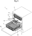
- the predetermined pivoting position in which the coupling element and the correspondence element of the first coupling unit 7 come into operative connection with one another, is just before reaching the Figures 4 to 6 shown position, in which the shelf 9 is moved out of the usable space 22 of the body 2 into a position in which the shelf 9 can be raised using the pivoting mechanism 4.
- the slotted guides 72, 82 preferably each have an inlet area 73, 83 which can be rounded off at the end or designed in the shape of a funnel. Shortly before the fully extended position of the shelf 9 is reached, the inlet area 73 takes over the protection of the lever arm 51 against pivoting up too early.
- the inlet areas 73, 83 can be of different lengths depending on the requirements. So shows in particular 3 a second coupling unit 8 with a relatively short lead-in area 83, while in an alternative sub-variant, shown in 8 , the inlet area 83 is dimensioned somewhat longer, whereby the shelf 9 as a whole can be extended somewhat further out of the usable space 22 of the body 2 in the extension direction x.
- the tray 9 Due to the special design of the slotted guide 82 with a relatively long entry area 83, the tray 9 is moved counter to the pull-out direction x while it is being pivoted up.
- the slotted guide 72 of the first coupling unit 7 in the first embodiment variant is shaped in such a way that the horizontally running inlet area 73 has an im Substantially vertically downwardly extending sub-section, at the end of which in turn extends a dead center section angled at right angles to this.
- the connecting link 82 can also be designed as a straight line or as a free-form curve, as a result of which the running path of the running rail 32 can be controlled as required during pivoting up.
- the running rail is only fixed to one of the two pivoting levers 41, 42.
- This dead center section serves to store 9 in their in the 11 and 12 shown upper raised end position without force, so that the tray 9 remains in this position without further actuation by a user.
- the shape of the slotted guide 72 is primarily geared towards a gradient that is matched to an optimal course of the actuation force.
- the actuating force can be optimized during the pivoting process by a targeted change in the shape of the link guide 72 to the application and the available pivoting range.
- the figures 9 and 10 show the dishwasher and the swivel mechanism 4 in the slightly raised position, in which the roller 71 of the first coupling unit 7 has already entered the next section from the inlet area 73, while the roller 81 of the second coupling unit 8 is positioned at the transition to the part-circular section.
- the link guide 82 of the second coupling unit 8 is formed on the same swivel arm 41 as the link guide 72 of the first coupling unit 7.
- edge 55 of the lever arm 51 and the stop 413 on the first swivel arm 41 form a safeguard against the lever arm 51 being raised too early during the extension of the tray 9 .
- the link guide 72 is designed as a curve with a changing curve radius.
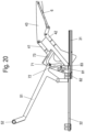
- the 19 and 20 show the second embodiment variant of this sliding and pivoting mechanism in the slightly raised position of the shelf 9, in which the rollers 71, 81 are retracted into the curved area of the slotted guide 72 of the first coupling unit 7 and the part-circular area of the slotted guide 82 of the second coupling unit 8.
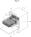
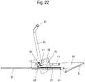
- FIGS 21 and 22 show the raised end position of the sliding and pivoting mechanism, in which the rollers 71, 81 have arrived at the rear end of the respective link guide 72, 82.
- the link guide 72 is shaped in such a way that, in the raised end position, the shelf 9 remains in a safe position without additional locking and is only lowered again by actuating the lever unit 5 .
- the link guide 72 By designing the link guide 72 as a curve with a changing curve radius, it is possible to achieve a smooth transition into the dead center area, which is advantageous compared to the first embodiment variant.
- the path between the dead center and the safe end position can be adjusted in a simple manner by the individual design of the connecting link 72 near the dead center area.
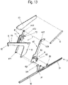
- the 23 shows the sliding and swivel mechanism again in a perspective exploded view.
- the link guide 72 of the first coupling unit 7 is not formed on one of the pivoting arms 41, 42, but on the rear end of the lever arm 51.
- link guide 72 represents the coupling element.
- this lever arm 51 has a larger surface area.
- the roller 71 embodied here as a correspondence element is fastened to the first swivel arm 41 in this case.
- the link guide 72 of the first coupling unit 7 is designed with an inlet area 73 and a curve adjoining this.
- rollers 71, 81 of the coupling units 7, 8 have also run into the inlet area 73, 83 and are shown in FIGS 29 and 30 into the respective curved areas of the slotted guides 72, 82 until the lever arm 51 is almost vertical in the raised end position and the rollers 71, 81 have reached the rear end of the slotted guides 72, 82.
- the link guide 72 is shaped in such a way that, in the raised end position, the shelf 9 remains in a safe position without additional locking and is only lowered again by actuating the lever unit 5 .
- the roller 71 also has the additional function of preventing the lever arm 51 from swiveling up too early while the shelf 9 is being pulled out, in that the edge 55 of the lever arm 51 runs under the roller 71 as a guide surface.
- FIGS. 34 to 45 show a fourth embodiment of a slide-pivoting mechanism according to the invention.
- roller of the first coupling unit is not attached directly to the end of the lever arm 51 remote from the handle part 52, but rather to an end of an articulated chain pivotably connected to the lever arm 51 and remote from the end of the lever arm 51.
- the articulated chain consists of two chain links 53, 54, each of which is preferably designed as an angled web with suitably shaped kinks are formed. It is also conceivable to link more than two such chain links together to form a link chain.
- the roller 71 of the first coupling unit 7 is rotatably mounted.
- the link guide 72 of the first coupling unit 7 is integrally formed or fastened to the first swivel arm 41 of the swivel mechanism 4 in a section of the first swivel arm 41 that is designed to be correspondingly wide.
- roller 71 of the first coupling unit 7 is threaded into the link guide 72 when the shelf 9 is moved out of the in 34 retracted position shown in 37 extended but not yet raised position shown.
- the roller 81 of the second coupling unit 8 is also guided into the entry area 83 of the link guide 82 of the second coupling unit 8 during this movement.
- the coupling element of the second coupling unit 8 is designed as a sliding or rolling element 81 rotatably arranged on the first swivel arm 41 .
- This sliding or rolling element 81 can be guided in a corresponding element arranged on the lever arm holder 34 of the lever arm 51 , in particular formed or fastened thereon and designed as a link guide 82 , for sequence control of the pivoting movement of the pivoting mechanism 4 .
- the articulated chain with the chain links 53, 54 shown here coupled to one another acts according to the toggle lever or rocker arm principle.
Landscapes
- Engineering & Computer Science (AREA)
- Chemical & Material Sciences (AREA)
- Combustion & Propulsion (AREA)
- Mechanical Engineering (AREA)
- General Engineering & Computer Science (AREA)
- Physics & Mathematics (AREA)
- Thermal Sciences (AREA)
- Drawers Of Furniture (AREA)
- Combinations Of Kitchen Furniture (AREA)
- Washing And Drying Of Tableware (AREA)
Applications Claiming Priority (3)
| Application Number | Priority Date | Filing Date | Title |
|---|---|---|---|
| DE102018111672 | 2018-05-15 | ||
| DE102018132802.8A DE102018132802A1 (de) | 2018-05-15 | 2018-12-19 | Schiebe-Schwenkmechanik einer Ablage eines Möbels oder Haushaltsgerätes und Möbel oder Haushaltsgerät |
| PCT/EP2019/061555 WO2019219433A1 (de) | 2018-05-15 | 2019-05-06 | Schiebe-schwenkmechanik einer ablage eines möbels oder haushaltsgerätes und möbel oder haushaltsgerät |
Publications (2)
| Publication Number | Publication Date |
|---|---|
| EP3793407A1 EP3793407A1 (de) | 2021-03-24 |
| EP3793407B1 true EP3793407B1 (de) | 2023-03-01 |
Family
ID=68419640
Family Applications (1)
| Application Number | Title | Priority Date | Filing Date |
|---|---|---|---|
| EP19722119.5A Active EP3793407B1 (de) | 2018-05-15 | 2019-05-06 | Schiebe-schwenkmechanik einer ablage eines möbels oder haushaltsgerätes und möbel oder haushaltsgerät |
Country Status (8)
| Country | Link |
|---|---|
| US (1) | US11445823B2 (zh) |
| EP (1) | EP3793407B1 (zh) |
| JP (1) | JP7385601B2 (zh) |
| KR (2) | KR20240118194A (zh) |
| CN (1) | CN112118769B (zh) |
| DE (1) | DE102018132802A1 (zh) |
| PL (1) | PL3793407T3 (zh) |
| WO (1) | WO2019219433A1 (zh) |
Families Citing this family (5)
| Publication number | Priority date | Publication date | Assignee | Title |
|---|---|---|---|---|
| DE102019107385A1 (de) * | 2019-03-22 | 2020-09-24 | Paul Hettich Gmbh & Co. Kg | Schiebe-Schwenkmechanik für eine Ablage eines Möbels oder Haushaltsgerätes und Möbel bzw. Haushaltsgerät |
| AU2019471000A1 (en) * | 2019-10-25 | 2022-02-24 | Electrolux Appliances Aktiebolag | Dishwasher |
| BE1029640B1 (de) * | 2021-07-30 | 2023-03-01 | Miele & Cie | Hebeeinrichtung für einen Spülkorb |
| EP4124280A1 (de) | 2021-07-30 | 2023-02-01 | Miele & Cie. KG | Verfahr- und hebemechanik |
| US11796245B2 (en) | 2021-12-13 | 2023-10-24 | Electrolux Home Products, Inc. | Swing-up storage assembly |
Family Cites Families (11)
| Publication number | Priority date | Publication date | Assignee | Title |
|---|---|---|---|---|
| US5115822A (en) * | 1991-03-20 | 1992-05-26 | Nichols Will E | Dishwasher basket assembly including lift mechanism |
| US20060066189A1 (en) * | 2004-09-30 | 2006-03-30 | Steve Bond | Shelf extending and lifting system |
| DE102012107993A1 (de) | 2012-08-29 | 2014-03-06 | Paul Hettich Gmbh & Co. Kg | Schiebe-Schwenkmechanik einer Ablage eines Möbels, Möbel und Geschirrspüler |
| DE102014213986B4 (de) * | 2014-07-17 | 2017-06-08 | BSH Hausgeräte GmbH | Haushaltsgeschirrspülmaschine |
| DE102014114285A1 (de) * | 2014-10-01 | 2016-04-07 | Paul Hettich Gmbh & Co. Kg | Schiebe-Schwenkmechanik einer Ablage eines Möbels oder Haushaltsgerätes, Möbel und Haushaltsgerät |
| DE102015102390A1 (de) | 2015-02-19 | 2016-08-25 | Paul Hettich Gmbh & Co. Kg | Schiebe-Schwenkmechanik einer Ablage eines Möbels oder Haushaltsgerätes, Möbel und Haushaltsgerät |
| DE102015102500A1 (de) * | 2015-02-20 | 2016-08-25 | Paul Hettich Gmbh & Co. Kg | Schiebe- und Hubmechanismus einer Ablage eines Möbels oder Haushaltsgeräts, Möbel und Haushaltsgerät |
| DE102016201727B4 (de) * | 2016-02-04 | 2018-02-15 | BSH Hausgeräte GmbH | Hebevorrichtung, Verfahren zum Betreiben einer Hebevorrichtung und Geschirrspülmaschine |
| DE102017107541A1 (de) * | 2016-04-08 | 2017-10-12 | BSH Hausgeräte GmbH | Schiebe- und Hubmechanismus für ein Möbel oder Haushaltsgerät und Möbel oder Haushaltsgerät mit einem derartigen Schiebe- und Hubmechanismus |
| DE102016121470A1 (de) * | 2016-11-09 | 2018-05-09 | Paul Hettich Gmbh & Co. Kg | Schiebe- und Hubmechanismus sowie Möbel und Haushaltsgerät |
| DE102016125040A1 (de) * | 2016-12-20 | 2018-06-21 | Paul Hettich Gmbh & Co. Kg | Möbel, Haushaltsgerät und Hubmechanismus einer Ablage eines Möbels oder Haushaltsgeräts |
-
2018
- 2018-12-19 DE DE102018132802.8A patent/DE102018132802A1/de active Pending
-
2019
- 2019-05-06 EP EP19722119.5A patent/EP3793407B1/de active Active
- 2019-05-06 CN CN201980032538.1A patent/CN112118769B/zh active Active
- 2019-05-06 KR KR1020247024872A patent/KR20240118194A/ko not_active Application Discontinuation
- 2019-05-06 WO PCT/EP2019/061555 patent/WO2019219433A1/de unknown
- 2019-05-06 KR KR1020207035277A patent/KR20210008850A/ko not_active Application Discontinuation
- 2019-05-06 JP JP2020564479A patent/JP7385601B2/ja active Active
- 2019-05-06 US US17/055,363 patent/US11445823B2/en active Active
- 2019-05-06 PL PL19722119.5T patent/PL3793407T3/pl unknown
Also Published As
| Publication number | Publication date |
|---|---|
| US11445823B2 (en) | 2022-09-20 |
| JP2021524301A (ja) | 2021-09-13 |
| KR20240118194A (ko) | 2024-08-02 |
| PL3793407T3 (pl) | 2023-07-10 |
| JP7385601B2 (ja) | 2023-11-22 |
| CN112118769A (zh) | 2020-12-22 |
| EP3793407A1 (de) | 2021-03-24 |
| US20210212459A1 (en) | 2021-07-15 |
| CN112118769B (zh) | 2022-11-22 |
| KR20210008850A (ko) | 2021-01-25 |
| DE102018132802A1 (de) | 2019-11-21 |
| WO2019219433A1 (de) | 2019-11-21 |
Similar Documents
| Publication | Publication Date | Title |
|---|---|---|
| EP3793407B1 (de) | Schiebe-schwenkmechanik einer ablage eines möbels oder haushaltsgerätes und möbel oder haushaltsgerät | |
| EP2424421B1 (de) | Vorrichtung zur höhenverstellung einer in einem haushaltsgerät über mindestens eine auszugsführung geführten ablage | |
| EP3151701B1 (de) | Schiebe-schwenkmechanik einer ablage eines möbels oder haushaltsgerätes, möbel und haushaltsgerät | |
| EP3151700B1 (de) | Schiebe-schwenkmechanik einer ablage eines möbels oder haushaltsgerätes, möbel und haushaltsgerät | |
| EP3092937B1 (de) | Geschirrspülmaschine mit einer spülgutaufnahme und einer hebevorrichtung für die spülgutaufnahme | |
| EP3151718B1 (de) | Geschirrspülmaschine, insbesondere haushaltsgeschirrspülmaschine | |
| DE112018004018B4 (de) | Schiebe-Schwenkmechanik einer Ablage eines Möbels oder Haushaltsgerätes und Möbel- bzw. Haushaltsgerät mit einer derartigen Schiebe-Schwenkmechanik | |
| DE102014114285A1 (de) | Schiebe-Schwenkmechanik einer Ablage eines Möbels oder Haushaltsgerätes, Möbel und Haushaltsgerät | |
| WO2016131778A1 (de) | Schiebe-schwenkmechanik einer ablage eines möbels und möbel | |
| EP2353438A2 (de) | Beschlag für Eckschränke | |
| WO2012159641A1 (de) | Beschlag für eckschränke sowie einzugvorrichtung für einen derartigen beschlag | |
| EP3169215B1 (de) | Haushaltsgeschirrspülmaschine | |
| EP3641619B1 (de) | Haushaltsgeschirrspülmaschine | |
| EP3941310B1 (de) | Schiebe-schwenkmechanik für eine ablage eines möbels oder haushaltsgerätes und möbel bzw. haushaltsgerät | |
| EP3624637A1 (de) | Hebemechanismus, möbel oder haushaltsgerät und schubkasten | |
| WO2018210563A1 (de) | Hubmechanismus einer ablage, möbel oder haushaltsgerät und schubkasten | |
| WO2016131777A1 (de) | Schiebe-schwenkmechanik einer ablage eines haushaltsgerätes und haushaltsgerät | |
| DE102018132916A1 (de) | Schiebe-Schwenkmechanik einer Ablage eines Möbels oder Haushaltsgerätes und Möbel oder Haushaltsgerät | |
| DE102018132800A1 (de) | Schiebe-Schwenkmechanik einer Ablage eines Möbels oder Haushaltsgerätes und Möbel oder Haushaltsgerät | |
| EP3338613B1 (de) | Haushaltsgeschirrspülmaschine | |
| EP1974631B1 (de) | Ausziehbeschlag für einen Schrank mit einer abgewinkelten Front | |
| DE2363435B2 (de) | Schrank, insbesondere kuechenschrank, mit im inneren angeordneten abfalleimer |
Legal Events
| Date | Code | Title | Description |
|---|---|---|---|
| STAA | Information on the status of an ep patent application or granted ep patent |
Free format text: STATUS: UNKNOWN |
|
| STAA | Information on the status of an ep patent application or granted ep patent |
Free format text: STATUS: THE INTERNATIONAL PUBLICATION HAS BEEN MADE |
|
| STAA | Information on the status of an ep patent application or granted ep patent |
Free format text: STATUS: THE INTERNATIONAL PUBLICATION HAS BEEN MADE |
|
| PUAI | Public reference made under article 153(3) epc to a published international application that has entered the european phase |
Free format text: ORIGINAL CODE: 0009012 |
|
| STAA | Information on the status of an ep patent application or granted ep patent |
Free format text: STATUS: REQUEST FOR EXAMINATION WAS MADE |
|
| 17P | Request for examination filed |
Effective date: 20201126 |
|
| AK | Designated contracting states |
Kind code of ref document: A1 Designated state(s): AL AT BE BG CH CY CZ DE DK EE ES FI FR GB GR HR HU IE IS IT LI LT LU LV MC MK MT NL NO PL PT RO RS SE SI SK SM TR |
|
| AX | Request for extension of the european patent |
Extension state: BA ME |
|
| DAV | Request for validation of the european patent (deleted) | ||
| DAX | Request for extension of the european patent (deleted) | ||
| STAA | Information on the status of an ep patent application or granted ep patent |
Free format text: STATUS: EXAMINATION IS IN PROGRESS |
|
| 17Q | First examination report despatched |
Effective date: 20211123 |
|
| RIN1 | Information on inventor provided before grant (corrected) |
Inventor name: GURR, ARNOLD Inventor name: KRUEGER, DAVID Inventor name: BEXTERMOELLER, BENJAMIN |
|
| GRAP | Despatch of communication of intention to grant a patent |
Free format text: ORIGINAL CODE: EPIDOSNIGR1 |
|
| STAA | Information on the status of an ep patent application or granted ep patent |
Free format text: STATUS: GRANT OF PATENT IS INTENDED |
|
| INTG | Intention to grant announced |
Effective date: 20221128 |
|
| GRAS | Grant fee paid |
Free format text: ORIGINAL CODE: EPIDOSNIGR3 |
|
| GRAA | (expected) grant |
Free format text: ORIGINAL CODE: 0009210 |
|
| STAA | Information on the status of an ep patent application or granted ep patent |
Free format text: STATUS: THE PATENT HAS BEEN GRANTED |
|
| AK | Designated contracting states |
Kind code of ref document: B1 Designated state(s): AL AT BE BG CH CY CZ DE DK EE ES FI FR GB GR HR HU IE IS IT LI LT LU LV MC MK MT NL NO PL PT RO RS SE SI SK SM TR |
|
| REG | Reference to a national code |
Ref country code: GB Ref legal event code: FG4D Free format text: NOT ENGLISH |
|
| REG | Reference to a national code |
Ref country code: CH Ref legal event code: EP Ref country code: AT Ref legal event code: REF Ref document number: 1550416 Country of ref document: AT Kind code of ref document: T Effective date: 20230315 |
|
| REG | Reference to a national code |
Ref country code: DE Ref legal event code: R096 Ref document number: 502019007096 Country of ref document: DE |
|
| REG | Reference to a national code |
Ref country code: IE Ref legal event code: FG4D Free format text: LANGUAGE OF EP DOCUMENT: GERMAN |
|
| REG | Reference to a national code |
Ref country code: LT Ref legal event code: MG9D |
|
| REG | Reference to a national code |
Ref country code: NL Ref legal event code: MP Effective date: 20230301 |
|
| PG25 | Lapsed in a contracting state [announced via postgrant information from national office to epo] |
Ref country code: RS Free format text: LAPSE BECAUSE OF FAILURE TO SUBMIT A TRANSLATION OF THE DESCRIPTION OR TO PAY THE FEE WITHIN THE PRESCRIBED TIME-LIMIT Effective date: 20230301 Ref country code: NO Free format text: LAPSE BECAUSE OF FAILURE TO SUBMIT A TRANSLATION OF THE DESCRIPTION OR TO PAY THE FEE WITHIN THE PRESCRIBED TIME-LIMIT Effective date: 20230601 Ref country code: LV Free format text: LAPSE BECAUSE OF FAILURE TO SUBMIT A TRANSLATION OF THE DESCRIPTION OR TO PAY THE FEE WITHIN THE PRESCRIBED TIME-LIMIT Effective date: 20230301 Ref country code: LT Free format text: LAPSE BECAUSE OF FAILURE TO SUBMIT A TRANSLATION OF THE DESCRIPTION OR TO PAY THE FEE WITHIN THE PRESCRIBED TIME-LIMIT Effective date: 20230301 Ref country code: HR Free format text: LAPSE BECAUSE OF FAILURE TO SUBMIT A TRANSLATION OF THE DESCRIPTION OR TO PAY THE FEE WITHIN THE PRESCRIBED TIME-LIMIT Effective date: 20230301 Ref country code: ES Free format text: LAPSE BECAUSE OF FAILURE TO SUBMIT A TRANSLATION OF THE DESCRIPTION OR TO PAY THE FEE WITHIN THE PRESCRIBED TIME-LIMIT Effective date: 20230301 |
|
| PG25 | Lapsed in a contracting state [announced via postgrant information from national office to epo] |
Ref country code: SE Free format text: LAPSE BECAUSE OF FAILURE TO SUBMIT A TRANSLATION OF THE DESCRIPTION OR TO PAY THE FEE WITHIN THE PRESCRIBED TIME-LIMIT Effective date: 20230301 Ref country code: NL Free format text: LAPSE BECAUSE OF FAILURE TO SUBMIT A TRANSLATION OF THE DESCRIPTION OR TO PAY THE FEE WITHIN THE PRESCRIBED TIME-LIMIT Effective date: 20230301 Ref country code: GR Free format text: LAPSE BECAUSE OF FAILURE TO SUBMIT A TRANSLATION OF THE DESCRIPTION OR TO PAY THE FEE WITHIN THE PRESCRIBED TIME-LIMIT Effective date: 20230602 Ref country code: FI Free format text: LAPSE BECAUSE OF FAILURE TO SUBMIT A TRANSLATION OF THE DESCRIPTION OR TO PAY THE FEE WITHIN THE PRESCRIBED TIME-LIMIT Effective date: 20230301 |
|
| PG25 | Lapsed in a contracting state [announced via postgrant information from national office to epo] |
Ref country code: SM Free format text: LAPSE BECAUSE OF FAILURE TO SUBMIT A TRANSLATION OF THE DESCRIPTION OR TO PAY THE FEE WITHIN THE PRESCRIBED TIME-LIMIT Effective date: 20230301 Ref country code: RO Free format text: LAPSE BECAUSE OF FAILURE TO SUBMIT A TRANSLATION OF THE DESCRIPTION OR TO PAY THE FEE WITHIN THE PRESCRIBED TIME-LIMIT Effective date: 20230301 Ref country code: PT Free format text: LAPSE BECAUSE OF FAILURE TO SUBMIT A TRANSLATION OF THE DESCRIPTION OR TO PAY THE FEE WITHIN THE PRESCRIBED TIME-LIMIT Effective date: 20230703 Ref country code: EE Free format text: LAPSE BECAUSE OF FAILURE TO SUBMIT A TRANSLATION OF THE DESCRIPTION OR TO PAY THE FEE WITHIN THE PRESCRIBED TIME-LIMIT Effective date: 20230301 Ref country code: CZ Free format text: LAPSE BECAUSE OF FAILURE TO SUBMIT A TRANSLATION OF THE DESCRIPTION OR TO PAY THE FEE WITHIN THE PRESCRIBED TIME-LIMIT Effective date: 20230301 |
|
| PG25 | Lapsed in a contracting state [announced via postgrant information from national office to epo] |
Ref country code: SK Free format text: LAPSE BECAUSE OF FAILURE TO SUBMIT A TRANSLATION OF THE DESCRIPTION OR TO PAY THE FEE WITHIN THE PRESCRIBED TIME-LIMIT Effective date: 20230301 Ref country code: IS Free format text: LAPSE BECAUSE OF FAILURE TO SUBMIT A TRANSLATION OF THE DESCRIPTION OR TO PAY THE FEE WITHIN THE PRESCRIBED TIME-LIMIT Effective date: 20230701 |
|
| REG | Reference to a national code |
Ref country code: DE Ref legal event code: R097 Ref document number: 502019007096 Country of ref document: DE |
|
| REG | Reference to a national code |
Ref country code: CH Ref legal event code: PL |
|
| PLBE | No opposition filed within time limit |
Free format text: ORIGINAL CODE: 0009261 |
|
| STAA | Information on the status of an ep patent application or granted ep patent |
Free format text: STATUS: NO OPPOSITION FILED WITHIN TIME LIMIT |
|
| PG25 | Lapsed in a contracting state [announced via postgrant information from national office to epo] |
Ref country code: MC Free format text: LAPSE BECAUSE OF FAILURE TO SUBMIT A TRANSLATION OF THE DESCRIPTION OR TO PAY THE FEE WITHIN THE PRESCRIBED TIME-LIMIT Effective date: 20230301 |
|
| REG | Reference to a national code |
Ref country code: BE Ref legal event code: MM Effective date: 20230531 |
|
| PG25 | Lapsed in a contracting state [announced via postgrant information from national office to epo] |
Ref country code: SI Free format text: LAPSE BECAUSE OF FAILURE TO SUBMIT A TRANSLATION OF THE DESCRIPTION OR TO PAY THE FEE WITHIN THE PRESCRIBED TIME-LIMIT Effective date: 20230301 Ref country code: MC Free format text: LAPSE BECAUSE OF FAILURE TO SUBMIT A TRANSLATION OF THE DESCRIPTION OR TO PAY THE FEE WITHIN THE PRESCRIBED TIME-LIMIT Effective date: 20230301 Ref country code: LU Free format text: LAPSE BECAUSE OF NON-PAYMENT OF DUE FEES Effective date: 20230506 Ref country code: LI Free format text: LAPSE BECAUSE OF NON-PAYMENT OF DUE FEES Effective date: 20230531 Ref country code: DK Free format text: LAPSE BECAUSE OF FAILURE TO SUBMIT A TRANSLATION OF THE DESCRIPTION OR TO PAY THE FEE WITHIN THE PRESCRIBED TIME-LIMIT Effective date: 20230301 Ref country code: CH Free format text: LAPSE BECAUSE OF NON-PAYMENT OF DUE FEES Effective date: 20230531 |
|
| 26N | No opposition filed |
Effective date: 20231204 |
|
| GBPC | Gb: european patent ceased through non-payment of renewal fee |
Effective date: 20230601 |
|
| REG | Reference to a national code |
Ref country code: IE Ref legal event code: MM4A |
|
| PG25 | Lapsed in a contracting state [announced via postgrant information from national office to epo] |
Ref country code: IE Free format text: LAPSE BECAUSE OF NON-PAYMENT OF DUE FEES Effective date: 20230506 |
|
| PG25 | Lapsed in a contracting state [announced via postgrant information from national office to epo] |
Ref country code: IE Free format text: LAPSE BECAUSE OF NON-PAYMENT OF DUE FEES Effective date: 20230506 Ref country code: GB Free format text: LAPSE BECAUSE OF NON-PAYMENT OF DUE FEES Effective date: 20230601 |
|
| PG25 | Lapsed in a contracting state [announced via postgrant information from national office to epo] |
Ref country code: IT Free format text: LAPSE BECAUSE OF FAILURE TO SUBMIT A TRANSLATION OF THE DESCRIPTION OR TO PAY THE FEE WITHIN THE PRESCRIBED TIME-LIMIT Effective date: 20230301 Ref country code: FR Free format text: LAPSE BECAUSE OF NON-PAYMENT OF DUE FEES Effective date: 20230531 Ref country code: BE Free format text: LAPSE BECAUSE OF NON-PAYMENT OF DUE FEES Effective date: 20230531 |
|
| PGFP | Annual fee paid to national office [announced via postgrant information from national office to epo] |
Ref country code: DE Payment date: 20240517 Year of fee payment: 6 |
|
| PGFP | Annual fee paid to national office [announced via postgrant information from national office to epo] |
Ref country code: PL Payment date: 20240426 Year of fee payment: 6 |
|
| PGFP | Annual fee paid to national office [announced via postgrant information from national office to epo] |
Ref country code: TR Payment date: 20240425 Year of fee payment: 6 |