EP3789000A1 - Retractor with space-saving features - Google Patents
Retractor with space-saving features Download PDFInfo
- Publication number
- EP3789000A1 EP3789000A1 EP20202733.0A EP20202733A EP3789000A1 EP 3789000 A1 EP3789000 A1 EP 3789000A1 EP 20202733 A EP20202733 A EP 20202733A EP 3789000 A1 EP3789000 A1 EP 3789000A1
- Authority
- EP
- European Patent Office
- Prior art keywords
- retractor
- spool
- webbing
- guide
- belt
- Prior art date
- Legal status (The legal status is an assumption and is not a legal conclusion. Google has not performed a legal analysis and makes no representation as to the accuracy of the status listed.)
- Withdrawn
Links
- 230000002411 adverse Effects 0.000 claims 2
- 208000027418 Wounds and injury Diseases 0.000 description 11
- 238000013461 design Methods 0.000 description 5
- 230000000007 visual effect Effects 0.000 description 5
- 238000010586 diagram Methods 0.000 description 2
- 238000011160 research Methods 0.000 description 2
- 238000004873 anchoring Methods 0.000 description 1
- 230000000295 complement effect Effects 0.000 description 1
- 230000006378 damage Effects 0.000 description 1
- 238000011161 development Methods 0.000 description 1
- 208000014674 injury Diseases 0.000 description 1
- 238000003780 insertion Methods 0.000 description 1
- 230000037431 insertion Effects 0.000 description 1
- 238000012423 maintenance Methods 0.000 description 1
- 230000002028 premature Effects 0.000 description 1
Images


Classifications
-
- A—HUMAN NECESSITIES
- A61—MEDICAL OR VETERINARY SCIENCE; HYGIENE
- A61G—TRANSPORT, PERSONAL CONVEYANCES, OR ACCOMMODATION SPECIALLY ADAPTED FOR PATIENTS OR DISABLED PERSONS; OPERATING TABLES OR CHAIRS; CHAIRS FOR DENTISTRY; FUNERAL DEVICES
- A61G3/00—Ambulance aspects of vehicles; Vehicles with special provisions for transporting patients or disabled persons, or their personal conveyances, e.g. for facilitating access of, or for loading, wheelchairs
- A61G3/08—Accommodating or securing wheelchairs or stretchers
- A61G3/0808—Accommodating or securing wheelchairs
-
- A—HUMAN NECESSITIES
- A61—MEDICAL OR VETERINARY SCIENCE; HYGIENE
- A61G—TRANSPORT, PERSONAL CONVEYANCES, OR ACCOMMODATION SPECIALLY ADAPTED FOR PATIENTS OR DISABLED PERSONS; OPERATING TABLES OR CHAIRS; CHAIRS FOR DENTISTRY; FUNERAL DEVICES
- A61G5/00—Chairs or personal conveyances specially adapted for patients or disabled persons, e.g. wheelchairs
- A61G5/10—Parts, details or accessories
-
- B—PERFORMING OPERATIONS; TRANSPORTING
- B60—VEHICLES IN GENERAL
- B60P—VEHICLES ADAPTED FOR LOAD TRANSPORTATION OR TO TRANSPORT, TO CARRY, OR TO COMPRISE SPECIAL LOADS OR OBJECTS
- B60P3/00—Vehicles adapted to transport, to carry or to comprise special loads or objects
- B60P3/06—Vehicles adapted to transport, to carry or to comprise special loads or objects for carrying vehicles
-
- B—PERFORMING OPERATIONS; TRANSPORTING
- B60—VEHICLES IN GENERAL
- B60P—VEHICLES ADAPTED FOR LOAD TRANSPORTATION OR TO TRANSPORT, TO CARRY, OR TO COMPRISE SPECIAL LOADS OR OBJECTS
- B60P7/00—Securing or covering of load on vehicles
- B60P7/06—Securing of load
- B60P7/08—Securing to the vehicle floor or sides
- B60P7/0823—Straps; Tighteners
- B60P7/0846—Straps; Tighteners winding up or storing of straps
-
- B—PERFORMING OPERATIONS; TRANSPORTING
- B65—CONVEYING; PACKING; STORING; HANDLING THIN OR FILAMENTARY MATERIAL
- B65H—HANDLING THIN OR FILAMENTARY MATERIAL, e.g. SHEETS, WEBS, CABLES
- B65H75/00—Storing webs, tapes, or filamentary material, e.g. on reels
- B65H75/02—Cores, formers, supports, or holders for coiled, wound, or folded material, e.g. reels, spindles, bobbins, cop tubes, cans, mandrels or chucks
- B65H75/04—Kinds or types
- B65H75/08—Kinds or types of circular or polygonal cross-section
- B65H75/14—Kinds or types of circular or polygonal cross-section with two end flanges
-
- B—PERFORMING OPERATIONS; TRANSPORTING
- B65—CONVEYING; PACKING; STORING; HANDLING THIN OR FILAMENTARY MATERIAL
- B65H—HANDLING THIN OR FILAMENTARY MATERIAL, e.g. SHEETS, WEBS, CABLES
- B65H75/00—Storing webs, tapes, or filamentary material, e.g. on reels
- B65H75/02—Cores, formers, supports, or holders for coiled, wound, or folded material, e.g. reels, spindles, bobbins, cop tubes, cans, mandrels or chucks
- B65H75/34—Cores, formers, supports, or holders for coiled, wound, or folded material, e.g. reels, spindles, bobbins, cop tubes, cans, mandrels or chucks specially adapted or mounted for storing and repeatedly paying-out and re-storing lengths of material provided for particular purposes, e.g. anchored hoses, power cables
- B65H75/38—Cores, formers, supports, or holders for coiled, wound, or folded material, e.g. reels, spindles, bobbins, cop tubes, cans, mandrels or chucks specially adapted or mounted for storing and repeatedly paying-out and re-storing lengths of material provided for particular purposes, e.g. anchored hoses, power cables involving the use of a core or former internal to, and supporting, a stored package of material
- B65H75/44—Constructional details
- B65H75/4402—Guiding arrangements to control paying-out and re-storing of the material
-
- B—PERFORMING OPERATIONS; TRANSPORTING
- B60—VEHICLES IN GENERAL
- B60Y—INDEXING SCHEME RELATING TO ASPECTS CROSS-CUTTING VEHICLE TECHNOLOGY
- B60Y2200/00—Type of vehicle
- B60Y2200/80—Other vehicles not covered by groups B60Y2200/10 - B60Y2200/60
- B60Y2200/84—Wheelchairs
Definitions
- the embodiments described and claimed herein relate generally to retractors.
- the retractor has a webbing guide that prevents twists from being wound onto the spool and keeps the webbing centered on the spool and/or supplies webbing off of the top of the spool.
- the retractors may be used with the wheelchair securement system disclosed in U.S. Patent No. 62/341,570 , which is incorporated herein in its entirety by reference.
- Wheelchair securement retractors often include several feet of webbing or other strap. At its proximal end, the webbing is attached to a spool. At its free end, the webbing is attached to an anchor, usually a hook, which engages and secures a wheelchair. When drawing webbing out from the retractor spool to secure the hook to the wheelchair, the operator may introduce twists into the webbing that can become wound onto the retractor spool when the webbing is retracted. These twists may jam the retractor or otherwise interfere with proper functioning of the retractor, while also increasing wear of the webbing. Similarly, as webbing enters the retractor it may go off-center and possibly interfere with and get damaged by the retractor gear/teeth.
- webbing guides serve the same purpose of keeping the webbing centered while being wound around a spool, and some may also prevent twisting of the webbing as well. For instance, it is common in the wheelchair securement industry to find a retractor cover with a "mouth” designed specifically to aid in guiding the webbing. Sometimes, retractors will include a small separate component mounted forward of the retractor frame. In all instances of existing webbing guides, their designs are limited to allow webbing to exit the retractor at a single point and offer a limited range of motion with respect to that webbing as it exits the retractor.
- existing guides serve as a "single-point" webbing guide unable to adapt to any variation from the angles of the webbing as it leaves the retractor.
- existing retractors used in a wheelchair environment where space constraints are significant take up more space than necessary, as the webbing must exit the spool typically straight off the bottom at a zero (0) degree angle, and then must pass through a separate webbing guide in the form of a retractor housing or other component mounted forward of the frame, both of which continue to take up much needed space.
- a webbing guide is pivotal about an axis of the spool which allows the belt to come off the spool of the retractor at any angle.
- This design may shift the webbing take-off point from the retractor rearward, thereby reducing the space needed for proper wheelchair securement while at the same time preventing twists and off-centering of the webbing, whereby the webbing will not interfere with and become damaged by the retractor teeth/gearing.
- the retractor is designed so that the webbing comes off of the top of the retractor spool, as opposed to an underside of the retractor spool like the prior art.
- This design may also shift the take-off point rearward and further eliminate some of the space used up by existing retractors.
- the housing for the retractor may have an open top and may be designed to protect users from contact with exposed gear/teeth and unintentional injury as a result of fingers entering the retractor top.
- the retractor may be designed in a way as to limit the range of motion of a webbing guide. For example, some international standards call for an operating range for securement. If those angles, for example, were to be from 30 degrees to 50 degrees, then the retractor can be designed to limit the rotating webbing guide to be operable only within that range.
- the webbing guide may feature a visual indicator to alert the user of a desired or optimal operation angle (or range of angles).
- This visual indicator may comprise many forms such as numerical values indicating the actual range, or a color system which will indicate via a positive or negative color value that the belt angles are within the operating range for effective securement.
- a lockable feature for the rotating webbing guide may be provided. Such a feature could serve to hold the webbing guide at an optimal angle for various purposes such as maintenance, storage, or to facilitate easier removal of the hooks from the retractor.
- the webbing guide may be provided with a spring loaded or tension bias.
- a spring loaded or tension bias could facilitate pushing the webbing guide to a predetermined angle, such as 90 degrees, for example.
- the webbing guide is at an angle that facilitates effective webbing ingress during a crash - resulting in improved rear excursions. Without a spring loading or tension bias, it would take the webbing itself to 'push' the webbing guide up to the 90 degree angle, therefore creating more friction which may prevent easy ingress of webbing through the webbing guide and into the retractor housing.
- the retractor 10 may include a housing 20 with an opening 30 for passing webbing 40 (or other types of belts or straps) from a spool unit 100.
- the webbing 40 may be secured at its proximal end to the spool unit 100 and a length of the webbing 40 may be wound around the spool unit 100, as shown.
- the spool unit 100 of the retractor 10 may be powered in one or both directions using a motor 60, speed reduction gearing 70, and drive shaft 80.
- the retractor 10 may additionally or alternatively be provided with spring-biasing which causes the spool unit 100 to pull webbing 40 onto the spool unit 100.
- the webbing 40 may be configured to leave the spool unit 100 at the top of the spool unit 100, as shown, or may be configured to leave the spool unit 100 at a bottom of the spool unit 100.
- the webbing 40 may be secured at its terminal end to an anchor, such as the hook 50 shown in the figures, for attachment to a wheelchair or other cargo.
- the spool unit 100 may comprise one or more sprockets 110, one or more guide plates 120, one or more webbing pads 130, one or more bearings 140, one or more end plates 150, one or more mandrels 160, and one or more webbing guide members 170.
- the spool unit 100 may include two sprockets 110 disposed at opposite sides of the spool unit 100.
- Each sprocket 110 may comprise a plurality of teeth 116 around its periphery for engagement with a locking pawl (not shown).
- the locking pawl (not shown) may selectively engage with the teeth 116 to lock the spool unit 100 in one or both directions (i.e., preventing webbing 40 from being pulled out of the retractor 10, and/or prevent webbing 40 from being wound into the retractor 10).
- the sprocket 110 may also include a central hole 114 for receiving the drive shaft 80 there through.
- the central hole 114 may be provided with a shape that corresponds to the shape of the drive shaft 80, whereby torque from the motor 60 may be communicated to the spool unit 100 through the speed reduction gearing 70, drive shaft 80 and sprocket 110.
- the sprocket may also include one or more holes (or female engagement members) 112 for receiving one or more projections (or male engagement members) 162 on the mandrel 160, whereby torque from the motor 60 may be further communicated through the sprocket 110 and to the mandrel 160.
- the holes 112 and projections 162 may have complementary shapes, such as the crescent shapes shown in the figures.
- the projections 162 may be press fit into the holes 112 to hold the spool unit 100 together as a unit and to align the teeth 116 and the central holes 114 of the two sprockets 110.
- the spool unit 100 may also include a spool 145 for holding webbing 40.
- the spool 145 may be defined by one mandrel 160 with two, spaced-apart end plates 150 affixed to the mandrel 160 near or at its opposite ends.
- Each end plate 150 may include a central opening 152 with an inwardly directed tab 154.
- the mandrel 160 may be configured in a circular, or semi-circular shape for insertion into the central openings 152 of the end plates 150, whereby webbing 40 may be connected to the mandrel 160 and wound around it, between the end plates 150, into a cylindrical shape.
- the mandrel 160 may include grooves 164 that are used to lock the end plates 150 into place.
- the mandrel 160 may be compressed a small amount so that the end plates 150 may be pushed into the grooves 164. Once the mandrel 160 is no longer compressed, it will return to its original diameter, captivating and locking the end plates 150 into the grooves 164. As shown, the mandrel 160 is semi-circular in shape with a gap 166 that receives the tab 154 on the end plates 150. The tabs 154 are configured for engagement in the gap 166 of the mandrel 160, whereby torque from the motor 60 may be further communicated through the mandrel 160 and to the end plates 150, whereby the mandrel 160 and end plates 150 rotate together.
- the spool unit 100 may include a rotatable webbing guide 115 with a guide opening 175 that receives and guides webbing 40 straight onto the spool 145 and prevent twists in the webbing 40 from being introduced onto the spool 145.
- the webbing guide 115 is rotatable about a periphery of the spool 145.
- the webbing guide 115 maintains the webbing 40 aligned with the spool 145, preventing the webbing from crossing the sprockets 110 therefore reducing premature wear.
- the opening 175 of the webbing guide 115 also presents a narrow, elongated slot that allows the webbing 40 which prevents twisting of the webbing 40 within the spool 145.
- the webbing guide 115 may further ensure that the webbing 40 is always presented in a direct path with the circumference of the wound webbing 40 on the spool 145, whereby the loads at the retractor and on the anchoring point may be reduced.
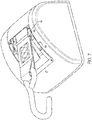
- the webbing guide 115 may include a visual indicator 180, such as the one shown in Figure 7 , which alerts a user via a numerical or color value that the belt angle is optimized for effective wheelchair securement.
- the visual indicator 180 may comprise an arrow indicator 182 on the webbing guide 115 that is adjacent a colored or lined gauge 184, that may have the angle number (such as "45°") and/or a color (such as green) indicating a normal and/or optimal operating angle, and an angle number (such as "0°” and/or "90°") and/or a color (such as red) indicating an upper and/or lower angle limit.
- the webbing guide 115 may further be provided with a spring bias, which reduces excursions by positioning the guide 115 in an ideal geometry to maximize webbing ingress.
- the guide opening 175 may be defined by two, oppositely positioned guide plates 120 that are separated by a pair of spaced-apart webbing guide members 170.
- the guide opening 175 may alternatively be defined by the pair of webbing guide members 170 and webbing pads 130 that are disposed between the webbing guide members 170 and the guide plates 120.
- the webbing guide members 170 may comprise cylinders or other longitudinal members that have curved or smooth edges and/or surfaces to reduce wear on the webbing 40 as it passes through the guide opening 175
- the webbing pads 130 are provided with curved or smooth edges and/or surfaces to reduce wear on the webbing 40 as it passes through the guide opening 175.
- the guide opening 175 may be provided by a unitary structure with smooth or curved edges.
- the guide plates 120 may include apertures 124 that alight with apertures 134 on the webbing pads 130. Apertures 124 and 134 may receive screws 135 that engage with threaded openings 174 at the opposite ends of the webbing guide members 170. In this respect, screws hold together guide plates 120, webbing pads 130, and webbing guide members 170, where the webbing pads 130 are captivated between the webbing guide members 170 and guide plates 120 once the screws are torqued down.
- the guide plates 120 of the webbing guide 115 may include a central opening 122 with a diameter slightly larger than the diameter of the mandrel 160, whereby the central opening 122 can receive the mandrel 160 and the webbing guide 115 can rotate about the mandrel.
- the width of the webbing guide 115 is slightly larger than the width of the spool 145, whereby the guide plates 120 are positioned outside of the end plates 150, but inside of the sprockets 110, as best shown in Figure 4 .
- Thrust bearings 140 are provided between each set of end plates 150 and guide plates 120, which allows the webbing guide 115 to rotate freely about its axis of rotation, independent from the remaining components of the spool unit 100, even when the webbing 40 enters the guide opening 175 at an angle and pulls the webbing guide 115 laterally.
- the webbing guide 115 is capable of guiding the webbing 40 onto a spool 145, permitting it to enter and exit the retractor case at different angles along a 360° rotation.
- the webbing guide 115 freely rotates 360° about the axis of the spool 145 allowing the webbing 40 to exit the retractor case at different angles.
- retractors 10 can be installed in various positions reducing the space required to secure an object.
- the retractor 10 shown in Figure 2 could be turned around where the webbing 40 and hook 50 exit from the rear of the retractor 10 (in which case the webbing 40 would be coming off of the bottom of the spool 145, rather than the top of the spool 145 as shown).
- the rotation of the webbing guide 115 may be limited to a range of angles.
- the embodiment shown in Figure 1 includes a housing 20 with an opening 30 that restricts the rotational movement of the webbing guide to a certain, predetermined range of angles.
- the retractor 10 depicted in Figures 1-5 may provide space savings in a wheelchair securement system, where webbing ideally should extend between the retractor and the wheelchair at an angle of approximately 35-55°, when compared to prior art systems that present webbing off of the bottom of the spool and include a fixed webbing guide positioned forward of the retractor.
- the space savings are best depicted in Figures 6A and 6B .
Landscapes
- Health & Medical Sciences (AREA)
- Public Health (AREA)
- Engineering & Computer Science (AREA)
- Animal Behavior & Ethology (AREA)
- General Health & Medical Sciences (AREA)
- Veterinary Medicine (AREA)
- Life Sciences & Earth Sciences (AREA)
- Transportation (AREA)
- Mechanical Engineering (AREA)
- Automotive Seat Belt Assembly (AREA)
- Storing, Repeated Paying-Out, And Re-Storing Of Elongated Articles (AREA)
- Surgical Instruments (AREA)
- Toilet Supplies (AREA)
- Air Bags (AREA)
Applications Claiming Priority (3)
| Application Number | Priority Date | Filing Date | Title |
|---|---|---|---|
| US15/339,360 US10166907B2 (en) | 2016-10-31 | 2016-10-31 | Retractor with space-saving features |
| EP17804021.8A EP3531999B1 (en) | 2016-10-31 | 2017-10-30 | Retractor with space-saving features |
| PCT/US2017/059034 WO2018081706A1 (en) | 2016-10-31 | 2017-10-30 | Retractor with space-saving features |
Related Parent Applications (2)
| Application Number | Title | Priority Date | Filing Date |
|---|---|---|---|
| EP17804021.8A Division-Into EP3531999B1 (en) | 2016-10-31 | 2017-10-30 | Retractor with space-saving features |
| EP17804021.8A Division EP3531999B1 (en) | 2016-10-31 | 2017-10-30 | Retractor with space-saving features |
Publications (1)
| Publication Number | Publication Date |
|---|---|
| EP3789000A1 true EP3789000A1 (en) | 2021-03-10 |
Family
ID=60451176
Family Applications (2)
| Application Number | Title | Priority Date | Filing Date |
|---|---|---|---|
| EP20202733.0A Withdrawn EP3789000A1 (en) | 2016-10-31 | 2017-10-30 | Retractor with space-saving features |
| EP17804021.8A Active EP3531999B1 (en) | 2016-10-31 | 2017-10-30 | Retractor with space-saving features |
Family Applications After (1)
| Application Number | Title | Priority Date | Filing Date |
|---|---|---|---|
| EP17804021.8A Active EP3531999B1 (en) | 2016-10-31 | 2017-10-30 | Retractor with space-saving features |
Country Status (10)
| Country | Link |
|---|---|
| US (3) | US10166907B2 (https=) |
| EP (2) | EP3789000A1 (https=) |
| JP (1) | JP7604097B2 (https=) |
| KR (1) | KR102446495B1 (https=) |
| CN (1) | CN109922769A (https=) |
| AU (1) | AU2017348422B2 (https=) |
| BR (1) | BR112019008784B1 (https=) |
| CA (1) | CA3041528A1 (https=) |
| DK (1) | DK3531999T3 (https=) |
| WO (1) | WO2018081706A1 (https=) |
Families Citing this family (5)
| Publication number | Priority date | Publication date | Assignee | Title |
|---|---|---|---|---|
| KR102372784B1 (ko) | 2016-05-25 | 2022-03-08 | 발레다 컴퍼니 (디/비/에이 큐′스트레인트) | 윈치 기구를 갖는 이동 장치 고정 시스템 |
| US10166907B2 (en) * | 2016-10-31 | 2019-01-01 | Valeda Company | Retractor with space-saving features |
| TWI730598B (zh) * | 2020-01-20 | 2021-06-11 | 方重懿 | 輪椅束緊裝置 |
| CN114099163B (zh) * | 2020-08-31 | 2023-02-10 | 比亚迪股份有限公司 | 一种轨道车辆的轮椅固定系统及轨道车辆 |
| US12453664B2 (en) | 2022-01-07 | 2025-10-28 | Valeda Company, Llc | Retractor restraint sensor assembly and stop |
Citations (6)
| Publication number | Priority date | Publication date | Assignee | Title |
|---|---|---|---|---|
| US4243350A (en) * | 1978-02-06 | 1981-01-06 | Hall Robert E | Winch load fastening apparatus |
| GB2064302A (en) * | 1979-11-28 | 1981-06-17 | Nissan Motor | Casing for seat-belt retractor |
| GB2398547A (en) * | 2003-02-24 | 2004-08-25 | Autoliv Dev | Seat belt retractor with rotatable guide member |
| WO2015144099A2 (en) * | 2014-03-24 | 2015-10-01 | Api Cz S.R.O. | Device for fastening a loose object, especially a wheelchair, to a vehicle floor |
| WO2017205696A1 (en) * | 2016-05-25 | 2017-11-30 | Valeva Company (D/B/A "Q'straint, Inc.") | Mobility device securement system with winch apparatus |
| EP3463238A1 (en) * | 2016-05-25 | 2019-04-10 | Valeda Company LLC (d/b/a Q'Straint) | Mobility device securement system with winch apparatus |
Family Cites Families (22)
| Publication number | Priority date | Publication date | Assignee | Title |
|---|---|---|---|---|
| US745013A (en) * | 1903-03-19 | 1903-11-24 | John H Heisey | Wire-stretcher. |
| US902647A (en) * | 1907-01-30 | 1908-11-03 | Frederick Day | Suspensory device. |
| US2178693A (en) * | 1936-05-26 | 1939-11-07 | Mcmullen John | Automobile securing device |
| US3140850A (en) * | 1963-04-29 | 1964-07-14 | Brandon Equipment Company Inc | Vehicle tie down apparatus |
| US3679175A (en) * | 1969-11-24 | 1972-07-25 | American Chain & Cable Co | Energy absorbing tie-down winch |
| US4045002A (en) * | 1975-04-14 | 1977-08-30 | Miller Errol S | Multi-purpose load winch |
| JPS58182757U (ja) * | 1982-06-01 | 1983-12-06 | 日産自動車株式会社 | リトラクタ |
| JPH0580924U (ja) * | 1992-03-30 | 1993-11-02 | 三菱自動車工業株式会社 | サスペンションシートのベルトアンカー構造 |
| US5494387A (en) * | 1994-04-13 | 1996-02-27 | Ruegg; Thomas A. | Universal apparatus for cargo lash tensioning |
| US6113325A (en) * | 1997-09-29 | 2000-09-05 | Craft; Richard D. | Wheelchair restraint system for a transportation vehicle |
| US6287060B1 (en) * | 2000-07-20 | 2001-09-11 | Jean Marc Girardin | Wheelchair restraint system |
| CN2458273Y (zh) * | 2001-01-17 | 2001-11-07 | 何圳钦 | 绞车 |
| US6899497B2 (en) * | 2001-11-14 | 2005-05-31 | Edgardo Cardona | Mobility aid securement for vehicles |
| JP2005027782A (ja) | 2003-07-09 | 2005-02-03 | Daihatsu Motor Co Ltd | 車両における車椅子固定装置 |
| JP2006290124A (ja) | 2005-04-08 | 2006-10-26 | Takata Corp | シートベルトリトラクタおよびこれを備えたシートベルト装置 |
| JP4916733B2 (ja) | 2006-02-22 | 2012-04-18 | 本田技研工業株式会社 | 車椅子固定用ベルト装置 |
| US8047751B2 (en) * | 2007-07-31 | 2011-11-01 | Midwest Precision Products, Inc. | Wheel chock with restraint |
| US9248999B2 (en) * | 2009-09-25 | 2016-02-02 | Harry Xydias | Level wind arm for a winch assembly |
| US8516979B2 (en) * | 2010-09-27 | 2013-08-27 | Joseph Ek | Retractable leash with automatic braking mechanism |
| JP2012076704A (ja) * | 2010-10-05 | 2012-04-19 | Tokai Rika Co Ltd | ウェビング巻取装置 |
| US9908749B2 (en) * | 2010-11-12 | 2018-03-06 | Harken, Inc. | Block |
| US10166907B2 (en) * | 2016-10-31 | 2019-01-01 | Valeda Company | Retractor with space-saving features |
-
2016
- 2016-10-31 US US15/339,360 patent/US10166907B2/en active Active
-
2017
- 2017-10-30 AU AU2017348422A patent/AU2017348422B2/en not_active Ceased
- 2017-10-30 JP JP2019544794A patent/JP7604097B2/ja active Active
- 2017-10-30 BR BR112019008784-2A patent/BR112019008784B1/pt not_active IP Right Cessation
- 2017-10-30 CA CA3041528A patent/CA3041528A1/en active Pending
- 2017-10-30 EP EP20202733.0A patent/EP3789000A1/en not_active Withdrawn
- 2017-10-30 EP EP17804021.8A patent/EP3531999B1/en active Active
- 2017-10-30 CN CN201780067254.7A patent/CN109922769A/zh active Pending
- 2017-10-30 KR KR1020197013625A patent/KR102446495B1/ko active Active
- 2017-10-30 WO PCT/US2017/059034 patent/WO2018081706A1/en not_active Ceased
- 2017-10-30 DK DK17804021.8T patent/DK3531999T3/da active
-
2018
- 2018-11-27 US US16/201,156 patent/US11597312B2/en active Active
-
2023
- 2023-02-28 US US18/175,817 patent/US20230202379A1/en active Pending
Patent Citations (6)
| Publication number | Priority date | Publication date | Assignee | Title |
|---|---|---|---|---|
| US4243350A (en) * | 1978-02-06 | 1981-01-06 | Hall Robert E | Winch load fastening apparatus |
| GB2064302A (en) * | 1979-11-28 | 1981-06-17 | Nissan Motor | Casing for seat-belt retractor |
| GB2398547A (en) * | 2003-02-24 | 2004-08-25 | Autoliv Dev | Seat belt retractor with rotatable guide member |
| WO2015144099A2 (en) * | 2014-03-24 | 2015-10-01 | Api Cz S.R.O. | Device for fastening a loose object, especially a wheelchair, to a vehicle floor |
| WO2017205696A1 (en) * | 2016-05-25 | 2017-11-30 | Valeva Company (D/B/A "Q'straint, Inc.") | Mobility device securement system with winch apparatus |
| EP3463238A1 (en) * | 2016-05-25 | 2019-04-10 | Valeda Company LLC (d/b/a Q'Straint) | Mobility device securement system with winch apparatus |
Also Published As
| Publication number | Publication date |
|---|---|
| EP3531999A1 (en) | 2019-09-04 |
| EP3531999B1 (en) | 2020-12-02 |
| KR102446495B1 (ko) | 2022-09-23 |
| AU2017348422A1 (en) | 2019-05-23 |
| DK3531999T3 (en) | 2020-12-14 |
| WO2018081706A1 (en) | 2018-05-03 |
| JP2019535461A (ja) | 2019-12-12 |
| US20190092214A1 (en) | 2019-03-28 |
| US20230202379A1 (en) | 2023-06-29 |
| KR20190104512A (ko) | 2019-09-10 |
| US20180118088A1 (en) | 2018-05-03 |
| JP7604097B2 (ja) | 2024-12-23 |
| BR112019008784A2 (pt) | 2019-07-16 |
| US11597312B2 (en) | 2023-03-07 |
| US10166907B2 (en) | 2019-01-01 |
| AU2017348422B2 (en) | 2022-12-08 |
| BR112019008784B1 (pt) | 2023-03-21 |
| CA3041528A1 (en) | 2018-05-03 |
| CN109922769A (zh) | 2019-06-21 |
Similar Documents
| Publication | Publication Date | Title |
|---|---|---|
| US20230202379A1 (en) | Retractor with space saving features | |
| EP1296850B1 (de) | Spannratsche mit gurtmagazin und gurtmagazin | |
| EP3747697B1 (en) | Manual belt-winding safety tensioning device for automobile | |
| US9150392B2 (en) | Winch | |
| EP2700344A1 (en) | Paper dispenser having a one-way spring clutch | |
| SE500013C2 (sv) | Banduppsamlare | |
| SE418384B (sv) | Med en sperranordning forsett friktionslas for spenning och fastlasning av ett bojligt festelement sasom en gordel eller en lina | |
| DE102016207739A1 (de) | Leinenaufbewahrungsvorrichtung | |
| US4236694A (en) | Manual winch with safety clutch, especially as a power source in nursing for lifting patients | |
| DE3933303A1 (de) | Gurt-rueckziehvorrichtung | |
| DE112017006688T5 (de) | Rückhaltesystem für ein sitzgurtschloss | |
| DE102017115121A1 (de) | Gurtaufwickelvorrichtung | |
| EP3185971B1 (en) | Automatically releasable hose reel assembly | |
| EP0624387B1 (de) | Abseil- und Aufseilgerät | |
| CA2236621C (en) | Hand operated chain block | |
| EP2285628B1 (de) | Gurtstraffer mit einem metallband zur kraftübertragung | |
| DE4320854A1 (de) | Sicherheitsgurtanordnung für Kraftfahrzeuge mit Straffervorrichtung | |
| DE10050000A1 (de) | Spannratsche mit Gurtmagazin | |
| DE102016213670A1 (de) | Leinenaufbewahrungsvorrichtung | |
| DE3926370A1 (de) | Sicherheitsgurtrollenvorrichtung | |
| AU2007101196A4 (en) | An Improved Hose Reel | |
| CN109131205A (zh) | 安全带卷取装置 | |
| EP2682362B1 (de) | Longiermittel | |
| SE521302C2 (sv) | Anordning för upplindning av böjliga långsträckta element | |
| DE1994732U (de) | Spule fuer bandfoermige datentraeger. |
Legal Events
| Date | Code | Title | Description |
|---|---|---|---|
| PUAI | Public reference made under article 153(3) epc to a published international application that has entered the european phase |
Free format text: ORIGINAL CODE: 0009012 |
|
| STAA | Information on the status of an ep patent application or granted ep patent |
Free format text: STATUS: THE APPLICATION HAS BEEN PUBLISHED |
|
| AC | Divisional application: reference to earlier application |
Ref document number: 3531999 Country of ref document: EP Kind code of ref document: P |
|
| AK | Designated contracting states |
Kind code of ref document: A1 Designated state(s): AL AT BE BG CH CY CZ DE DK EE ES FI FR GB GR HR HU IE IS IT LI LT LU LV MC MK MT NL NO PL PT RO RS SE SI SK SM TR |
|
| STAA | Information on the status of an ep patent application or granted ep patent |
Free format text: STATUS: REQUEST FOR EXAMINATION WAS MADE |
|
| 17P | Request for examination filed |
Effective date: 20210910 |
|
| RBV | Designated contracting states (corrected) |
Designated state(s): AL AT BE BG CH CY CZ DE DK EE ES FI FR GB GR HR HU IE IS IT LI LT LU LV MC MK MT NL NO PL PT RO RS SE SI SK SM TR |
|
| RIC1 | Information provided on ipc code assigned before grant |
Ipc: A61G 3/08 20060101AFI20230803BHEP |
|
| GRAP | Despatch of communication of intention to grant a patent |
Free format text: ORIGINAL CODE: EPIDOSNIGR1 |
|
| STAA | Information on the status of an ep patent application or granted ep patent |
Free format text: STATUS: GRANT OF PATENT IS INTENDED |
|
| INTG | Intention to grant announced |
Effective date: 20230915 |
|
| STAA | Information on the status of an ep patent application or granted ep patent |
Free format text: STATUS: THE APPLICATION IS DEEMED TO BE WITHDRAWN |
|
| 18D | Application deemed to be withdrawn |
Effective date: 20240126 |