EP3788992B1 - Automatische ausscheidungsbehandlungsvorrichtung und gebäude - Google Patents
Automatische ausscheidungsbehandlungsvorrichtung und gebäude Download PDFInfo
- Publication number
- EP3788992B1 EP3788992B1 EP19836449.9A EP19836449A EP3788992B1 EP 3788992 B1 EP3788992 B1 EP 3788992B1 EP 19836449 A EP19836449 A EP 19836449A EP 3788992 B1 EP3788992 B1 EP 3788992B1
- Authority
- EP
- European Patent Office
- Prior art keywords
- drainage
- pipe
- cup
- piping
- tank
- Prior art date
- Legal status (The legal status is an assumption and is not a legal conclusion. Google has not performed a legal analysis and makes no representation as to the accuracy of the status listed.)
- Active
Links
Images
Classifications
-
- A—HUMAN NECESSITIES
- A61—MEDICAL OR VETERINARY SCIENCE; HYGIENE
- A61G—TRANSPORT, PERSONAL CONVEYANCES, OR ACCOMMODATION SPECIALLY ADAPTED FOR PATIENTS OR DISABLED PERSONS; OPERATING TABLES OR CHAIRS; CHAIRS FOR DENTISTRY; FUNERAL DEVICES
- A61G9/00—Bed-pans, urinals or other sanitary devices for bed-ridden persons; Cleaning devices therefor, e.g. combined with toilet-urinals
- A61G9/02—Cleaning devices
-
- A—HUMAN NECESSITIES
- A61—MEDICAL OR VETERINARY SCIENCE; HYGIENE
- A61F—FILTERS IMPLANTABLE INTO BLOOD VESSELS; PROSTHESES; DEVICES PROVIDING PATENCY TO, OR PREVENTING COLLAPSING OF, TUBULAR STRUCTURES OF THE BODY, e.g. STENTS; ORTHOPAEDIC, NURSING OR CONTRACEPTIVE DEVICES; FOMENTATION; TREATMENT OR PROTECTION OF EYES OR EARS; BANDAGES, DRESSINGS OR ABSORBENT PADS; FIRST-AID KITS
- A61F5/00—Orthopaedic methods or devices for non-surgical treatment of bones or joints; Nursing devices ; Anti-rape devices
- A61F5/44—Devices worn by the patient for reception of urine, faeces, catamenial or other discharge; Colostomy devices
- A61F5/451—Genital or anal receptacles
-
- A—HUMAN NECESSITIES
- A61—MEDICAL OR VETERINARY SCIENCE; HYGIENE
- A61G—TRANSPORT, PERSONAL CONVEYANCES, OR ACCOMMODATION SPECIALLY ADAPTED FOR PATIENTS OR DISABLED PERSONS; OPERATING TABLES OR CHAIRS; CHAIRS FOR DENTISTRY; FUNERAL DEVICES
- A61G9/00—Bed-pans, urinals or other sanitary devices for bed-ridden persons; Cleaning devices therefor, e.g. combined with toilet-urinals
- A61G9/003—Bed-pans
-
- A—HUMAN NECESSITIES
- A61—MEDICAL OR VETERINARY SCIENCE; HYGIENE
- A61F—FILTERS IMPLANTABLE INTO BLOOD VESSELS; PROSTHESES; DEVICES PROVIDING PATENCY TO, OR PREVENTING COLLAPSING OF, TUBULAR STRUCTURES OF THE BODY, e.g. STENTS; ORTHOPAEDIC, NURSING OR CONTRACEPTIVE DEVICES; FOMENTATION; TREATMENT OR PROTECTION OF EYES OR EARS; BANDAGES, DRESSINGS OR ABSORBENT PADS; FIRST-AID KITS
- A61F5/00—Orthopaedic methods or devices for non-surgical treatment of bones or joints; Nursing devices ; Anti-rape devices
- A61F5/44—Devices worn by the patient for reception of urine, faeces, catamenial or other discharge; Colostomy devices
- A61F5/442—Devices worn by the patient for reception of urine, faeces, catamenial or other discharge; Colostomy devices having irrigation ports or means
-
- A—HUMAN NECESSITIES
- A61—MEDICAL OR VETERINARY SCIENCE; HYGIENE
- A61G—TRANSPORT, PERSONAL CONVEYANCES, OR ACCOMMODATION SPECIALLY ADAPTED FOR PATIENTS OR DISABLED PERSONS; OPERATING TABLES OR CHAIRS; CHAIRS FOR DENTISTRY; FUNERAL DEVICES
- A61G9/00—Bed-pans, urinals or other sanitary devices for bed-ridden persons; Cleaning devices therefor, e.g. combined with toilet-urinals
-
- E—FIXED CONSTRUCTIONS
- E03—WATER SUPPLY; SEWERAGE
- E03C—DOMESTIC PLUMBING INSTALLATIONS FOR FRESH WATER OR WASTE WATER; SINKS
- E03C1/00—Domestic plumbing installations for fresh water or waste water; Sinks
- E03C1/01—Domestic plumbing installations for fresh water or waste water; Sinks for combinations of baths, showers, sinks, wash-basins, closets, urinals, or the like
-
- E—FIXED CONSTRUCTIONS
- E03—WATER SUPPLY; SEWERAGE
- E03D—WATER-CLOSETS OR URINALS WITH FLUSHING DEVICES; FLUSHING VALVES THEREFOR
- E03D11/00—Other component parts of water-closets, e.g. noise-reducing means in the flushing system, flushing pipes mounted in the bowl, seals for the bowl outlet, devices preventing overflow of the bowl contents; devices forming a water seal in the bowl after flushing, devices eliminating obstructions in the bowl outlet or preventing backflow of water and excrements from the waterpipe
- E03D11/02—Water-closet bowls ; Bowls with a double odour seal optionally with provisions for a good siphonic action; siphons as part of the bowl
- E03D11/11—Bowls combined with a reservoir, e.g. containing apparatus for disinfecting or for disintegrating
-
- E—FIXED CONSTRUCTIONS
- E03—WATER SUPPLY; SEWERAGE
- E03D—WATER-CLOSETS OR URINALS WITH FLUSHING DEVICES; FLUSHING VALVES THEREFOR
- E03D3/00—Flushing devices operated by pressure of the water supply system flushing valves not connected to the water-supply main, also if air is blown in the water seal for a quick flushing
- E03D3/10—Flushing devices with pressure-operated reservoir, e.g. air chamber
-
- E—FIXED CONSTRUCTIONS
- E03—WATER SUPPLY; SEWERAGE
- E03D—WATER-CLOSETS OR URINALS WITH FLUSHING DEVICES; FLUSHING VALVES THEREFOR
- E03D5/00—Special constructions of flushing devices, e.g. closed flushing system
- E03D5/02—Special constructions of flushing devices, e.g. closed flushing system operated mechanically or hydraulically (or pneumatically) also details such as push buttons, levers and pull-card therefor
- E03D5/024—Operated hydraulically or pneumatically
-
- E—FIXED CONSTRUCTIONS
- E03—WATER SUPPLY; SEWERAGE
- E03F—SEWERS; CESSPOOLS
- E03F1/00—Methods, systems, or installations for draining-off sewage or storm water
- E03F1/006—Pneumatic sewage disposal systems; accessories specially adapted therefore
-
- A—HUMAN NECESSITIES
- A61—MEDICAL OR VETERINARY SCIENCE; HYGIENE
- A61G—TRANSPORT, PERSONAL CONVEYANCES, OR ACCOMMODATION SPECIALLY ADAPTED FOR PATIENTS OR DISABLED PERSONS; OPERATING TABLES OR CHAIRS; CHAIRS FOR DENTISTRY; FUNERAL DEVICES
- A61G2203/00—General characteristics of devices
- A61G2203/30—General characteristics of devices characterised by sensor means
Definitions
- the present invention relates to an automatic excretion disposal device and a building for automatically disposing of the excretions of persons to be cared for.
- the applicant has already proposed an automatic excretion disposal device which disposes of the excretions of a person to be cared for (see, for example, Patent Literature 1).
- This automatic excretion disposal device is equipped with a cup attached to the body of the person to be cared for, a suction unit which suctions the excretions into the cup, a sewage tank which stores the suctioned excretions, a cleaning unit which cleans the inside of the cup and the body, and a water supply tank which stores cleaning water and supplies the cleaning water to the cleaning unit.
- the body of the person to be cared for can be cleaned, and the excretions can be stored in the sewage tank after the disposal.
- Patent Literature 2 discloses the preamble of claim 1 and discloses an excrement treatment method including a step of opening a suction port of a suction valve of a sewage tank and closing a water discharge valve of the sewage tank; a step of sucking air in the sewage tank from an air inlet/outlet of the sewage tank and sucking a sewage from a pipe connected to a suction port of the suction valve to store the sewage; a step of closing the suction port of the suction valve of the sewage tank and opening the water discharge valve of the sewage tank; and a step of injecting a compressed air into the air inlet/outlet of the sewage tank to discharge the stored sewage to an outside from the water discharge valve.
- Patent Literature 3 discloses an excrement disposal device comprising a washing hose, an air supply hose, an excrement suction hose for sucking/discharging the excrement by an excrement discharge device, and a wearable body for excretion to which the hoses are connected.
- the excrement discharge device consists of a suction/discharge pump with a power source, an excrement tank, and a pressure converting part for switching the positive pressure and the negative pressure.
- the suction/discharge pump is a cylinder type pump, and is connected to the excrement tank by a hose via the pressure converting part, and the excrement tank is connected to the pressure converting part by the excrement suction hose.
- Patent Literature 4 discloses a user-worn device which is equipped with a diaper cup formed to have an approximately C-shaped cross-section for covering an abdomen to buttocks of a user, a base plate arranged underneath the buttocks, a plurality of fixed bumps rising on the base plate, and a plurality of variable bumps which are arranged between the fixed bumps on the base plate and extend in the direction perpendicular to the base plate in a manner to exceed the height of respective fixed bumps at the time when a fluid is introduced, the load of the user's buttocks is applied to either/both the fixed protruding parts or/and the variable bumps.
- Patent Literature 5 discloses an excreta treatment device which is characterized in that washing water from a water delivery pump of a water supply unit is injected into a main diaper cup body and washes a urinary apparatus and excreta, the excreta is sucked by work wind of an suction motor, the excreta and the washing water are separated and collected, only the work wind is purified and returned by an suction circulating pipe to the main diaper cup body for circulation; for the excreta treatment device, the suction circulating pipe is led out to a cooling unit outside an equipment storage box from a discharge side of the suction motor, and then the work wind in the suction circulating pipe in the cooling unit exchanges heat with outside air, is cooled and returned to a return box unit.
- An object of the present invention is to provide an automatic excretion disposal device and a building capable of reducing an occurrence of odor, while significantly reducing the burden on nursing staff members.
- An automatic excretion disposal device according to the technical solution, is defined in claim 1.
- a further aspect of the invention is given by a building comprising the automatic excretion disposal device defined by claim 4.
- an installation type water supply tank can be omitted to simplify a device configuration, and the burden on a nursing staff member can be significantly reduced.
- the pressure of the cleaning water to be supplied from the water pipe is reduced to a predetermined pressure value suitable for circulation in the device, the device can be directly connected to the water pipe.
- the drainage pump causes the drainage to directly flow out to a sewer or the like, while pulverizing the drainage, the installation type sewage tank can be omitted to simplify the device configuration, and the burden on the nursing staff member can be significantly reduced.
- the branch pipe branching from the air supply pipe is connected to the drainage pipe, it is possible to prevent odor from leaking into the living room of the person to be cared for and improve the living environment.
- the collecting unit is configured to generate a back pressure which assists the outflow of the sewage flowing out to the drainage pipe, using the flow of the air exhausted from the branch pipe, it is possible to smoothen the outflow of the drainage to the sewer.
- the suction motor may be configured to suck the inside of the cup, suck outside air from a gap generated between the cup and the body, cause the outside air to flow inside the air supply pipe, and prevent excretion and odor from leaking outside of the cup.
- the present invention it is possible to prevent the excretion and odor from leaking out, by sucking the outside air from the gap generated between the cup and the body, thereby improving the living environment.
- the present invention may be configured to further include a one-way valve that is provided in the middle of the drainage pipe connected to a downstream side of the drainage pipe and causes the drainage to flow in one direction to the collecting portion connected to the downstream side.
- the one-way valve since the one-way valve is provided, even when the suction motor operates and the inside of the tank reaches a negative pressure, it is possible to prevent the drainage from flowing backward from the drainage pipe into the tank.
- a one-way valve it may be constituted by a motor valve or the like.
- the present invention may be a building which includes a piping connected to the water supply, a piping connected to the sewer, and the automatic excretion disposal device described above.
- the automatic excretion disposal device can be installed, and it is possible to realize a nursing care facility which significantly reduces the burden on nursing staff member.
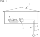
- an automatic excretion disposal device 1 is a device which automatically performs excretion disposal, is installed inside a building Y provided with a piping C connected to a water supply W, and a piping D connected to a sewer U, and is configured to be directly supplied with water from the water supply W and to directly drainage sewage to the sewer U.
- a piping C for the water supply W and a piping D for the sewer U connected to a wash basin Q are provided in a living room in which a person P to be cared stays.
- the pipings C and D may be connected to each of the water supply W and the sewer U, without being limited to the wash basin Q.
- the sewer U may be a septic tank.
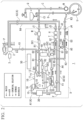
- the automatic excretion disposal device 1 is equipped with a cup 2 attached to the body of the person P to be cared, a tank 10 which stores sewage containing excretion discharged from the inside of the cup 2, a drainage pump 20 which causes sewage to flow out to the sewer U from the tank 10, a suction motor 30 which causes excretion to flow into the tank 10 from the cup 2, a chemical solution tank 40 which stores the chemical solution to be supplied to the cup 2, and a control device 50 which performs overall control of excretion disposal.
- the components other than the cup 2 are housed in a housing X.
- the cup 2 is formed to cover a region around the crotch of the person P to be cared (not shown).
- the detailed configuration such as the shape of the cup 2 is described, for example, in Patent Literature 1.
- the cup 2 has a contact part that comes into contact with the body of the person P to be cared.
- the contact part is formed of silicone resin, and improves the adhesion between the cup 2 and the body of the person P to be cared.
- the cup 2 temporarily receives excretion. Cleaning water is supplied to the cup 2 from the water supply W to clean the crotch or the like of the person P to be cared.
- the cup 2 is provided with a detection unit 3 for detecting excretion.
- the detection unit 3 is a capacitance sensor that electrically detects whether the excretion is solid or liquid. A cycle of the excretion disposal of the automatic excretion disposal device 1 is started on the basis of the detection result of the detection unit 3.
- the water supply W and the tank 10 are connected by a feed water pipe R1 via a branch piping C1 branching from the piping C.
- the branch piping C 1 and the feed water pipe R1 are formed by, for example, a flexible hose.
- the branch piping C1 and the feed water pipe R1 are connected by a detachable hose joint J1.
- a pressure reducing valve M which adjusts the water pressure is connected to a downstream side of the hose joint J1.
- the pressure reducing valve M reduces the pressure of the cleaning water supplied from the branch piping C1 to a predetermined water pressure.
- the predetermined water pressure is set to a pressure value such that the pressure of the cleaning water is suitable for circulation in the automatic excretion disposal device 1.
- a solenoid valve SV1 which causes the decompressed cleaning water to flow or blocks it, is provided on the downstream side of the pressure reducing valve M.
- the solenoid valve SV1 enters an ON-state after it is determined that excretions have been detected in the cup 2 by the detection unit 3 as described below, and supplies the cleaning water from the water supply W into the automatic excretion disposal device 1.
- the solenoid valve SV1 keeps the ON-state during an operation state of one cycle of the excretion disposal of the automatic excretion disposal device 1, and enters an OFF-state at the time when one cycle is completed.
- a feed water pipe R1 is connected to the tank 10 via a connection part Y1 on the downstream side of the solenoid valve SV1.
- the feed water pipe R1 supplies cleaning water to the tank 10 during one cycle of the excretion disposal, and cleans a predetermined region of the tank 10.
- the feed water pipe R1 branches at a branch part B1 on the upstream side of the connection part Y1.
- a branch pipe R2 branching from the feed water pipe R1 is connected to a connection part Y2 different from the connection part of the feed water pipe R1.
- the branch pipe R2 supplies the cleaning water to a region different from the region in the tank 10 that is cleaned with the cleaning water to be supplied from the feed water pipe R1.
- the cleaning effect in the tank 10 is enhanced by the feed water pipe R1 and the branch pipe R2.
- the branch pipe R2 is provided with a solenoid valve SV3 between the connection part Y2 and the branch part B1. After it is determined that excretion is detected in the cup 2, the solenoid valve SV3 repeats entering the ON-state and the OFF-state at predetermined time intervals in one cycle of the excretion disposal. After it is determined that the solid excretion is detected in the cup 2, the solenoid valve SV3 repeats a cycle during which an OFF-state is set for 5 seconds and then an ON-state is set for 10 seconds three times, and cleans the tank 10.
- the solenoid valve SV3 repeats a cycle during which an OFF-state is set for 5 seconds and then an ON-state is set for 10 seconds twice, and cleans the tank 10.
- the time flow of the solenoid valve SV3 can be changed by a program.
- the tank 10 is a container which temporarily stores sewage.
- the tank 10 and the cup 2 are connected by a sewage piping K1 to be described below for sewage disposal.
- the tank 10 is equipped with an air chamber 11 into which air enters, and a storage unit 12 provided below the air chamber 11.
- the air chamber 11 has a closed space S formed therein.
- the storage unit 12 is formed such that the diameter decreases downward.
- the storage unit 12 is provided with a detection unit 14 that detects a water level of the sewage.
- a drainage pump 20 is provided below the storage unit 12.
- a drainage pipe K2 which causes the drainage to flow out is connected to the downstream side of the drainage pump 20.
- the drainage pipe K2 is connected to a piping K3 via a hose joint J4.
- the piping K3 is formed by a flexible hose.
- the piping K3 is connected to a piping D for the sewer U.
- the drainage pump 20 is equipped with a rotary vane 22 on which a pulverizing cutter 23 to be driven by a motor 21 is formed.
- a motor 21 for example, a waterproof DC brushless motor is used.
- any other motor that generates a rotational driving force such as a DC brush motor or an AC motor, may be used, in addition to a DC brushless motor.
- the drainage pump 20 causes the solid matters contained in the drainage, in which the cleaning water directly supplied from the water supply W is mixed with the sewage, to forcibly flow out to the drainage pipe K2 connected to the sewer U, while finely pulverizing the solid matters with the pulverizing cutter 23 by the rotation of the rotary vanes 22.
- a one-way valve V2 which causes the drainage to flow to the sewer U side in one direction is provided in the middle of the drainage pipe K2.
- the one-way valve V2 prevents backflow from the drainage pipe K2 when the suction motor 30 operates as described below.
- a collecting unit G3 in which a branch pipe A5 to be described below joins is provided on the downstream side of the one-way valve V2.
- the air chamber 11 is provided with connection parts Y1 and Y2.
- the air chamber 11 and the sewage piping K1 are connected via the suction port 13.
- the air chamber 11 is connected to a suction motor 30 that sucks air into the space S via a piping A1.
- a separation device 15 which separates sewage and air is provided at a connection part between the piping A1 and the air chamber 11.
- the separation device 15 is provided with an air turbine motor 16 that provides a rotational driving force, and a rotary blade 17 that is rotated by the air turbine motor 16.
- the rotary blade 17 is equipped with a plurality of blades 18 formed radially from a rotary shaft.
- the air turbine motor 16 is driven by the suction pressure of the suction motor 30.
- the suction motor 30 may be of any type that generates a rotational driving force, such as a DC brush motor or an AC motor, in addition to a DC brushless motor.
- the air turbine motor 16 When the suction motor 30 operates to suck the air into the space S, the air turbine motor 16 is operated by the passing air and rotates the rotary blade 17. Then, the sewage adhering to the blade 18 of the rotary blade 17 is blown into the air chamber 11 by a centrifugal force, and only air is sucked from a gap between the plurality of blades 18.
- the suction motor 30 enters the ON-state in one cycle of the excretion disposal after it is determined that excretion is detected in the cup 2.
- a method other than the air turbine motor 16 may be used for separating air and dirt.
- the suction motor 30 operates for 15 seconds to enter a drying mode, and supplies air to the cup 2 to dry the inside of the cup 2 and the body of the person P to be cared.
- the air sucked by the suction motor 30 flows into a piping A2 that communicates with the outside of the housing X via an air filter F connected to the downstream side of the suction motor 30.
- the time flow of the suction motor 30 can be changed by a program.
- the air filter F removes fine particles and an odor of sewage mixed into the air flowing through the piping A1 with activated carbon or the like. Since the separation device 15 operates, the air filter F is rarely contaminated.
- the piping A2 connected to the downstream side of the air filter F is connected to an air piping A3 communicating with the cup 2 via a detachable hose joint J2 provided on the housing X.
- the air supply pipe A is constituted by the piping A1, the piping A2, and the air piping A3.
- a branch pipe A5 is connected between the air filter F and the hose joint J2 via a branch part B3.
- the downstream side of the branch pipe A5 is connected to the drainage pipe K2 via the collecting unit G3.
- a one-way valve V3 is provided between the branch part B3 of the branch pipe A5 and the collecting unit G3.
- the one-way valve V3 causes air to flow in one direction from the branch part B3 side to the collecting unit G3 side in the branch tube A5, and prevents inflow of drainage from the drainage pipe K2 to the branch part B3 side.
- the collecting unit G3 connects the branch pipe A5 and the drainage pipe K2, and is formed so that a flow line direction of the air flowing through the branch pipe A5 matches a streamline direction of the drainage flowing through the drainage pipe K2.
- the collecting unit G3 exhausts air having a positive pressure generated in the piping A2 to the drainage pipe K2 and generates an airflow on the downstream side of the collecting unit G3, thereby generating a back pressure for assisting the outflow of drainage flowing out to the drainage pipe K2. Due to the back pressure generated by the branch pipe A5, the drainage staying between the one-way valve V2 and the collecting unit G3 in the drainage pipe K2 easily flows out to the downstream side.
- the branch pipe A5 releases a positive pressure with respect to atmospheric pressure generated in the piping A2 by the outside air sucked by the suction motor 30 to the drainage pipe K2 as described below, and adjusts the pressure in the piping A2.
- the air containing odor is exhausted to the sewer U without being released to the atmosphere by the branch pipe A5. Therefore, the odor in the living room in which the person P to be cared stays is reduced by the branch pipe A5.
- the air piping A3 connected to the piping A2 is a piping which supplies air into the cup 2.
- the air piping A3 is formed by a flexible hose.
- the air supplied from the air piping A3 dries the pubic area and the anus of the person P to be cared after cleaning, as described below.
- the air supplied into the cup 2 is sucked into the tank 10 by the suction motor 30 through the sewage piping K1. Therefore, the air is basically circulated by the suction motor 30 through the tank 10, the piping A1, the piping A2, the air piping A3, the cup 2, the sewage piping K1, and the tank 10 in this order.
- the suction motor 30 generates a negative pressure for sucking the inside of the cup. Although it is desirable that the cup 2 and the body of the person P to be cared are completely in close contact with each other, a gap may be generated therebetween depending on conditions such as the posture of the person P to be cared and individual differences.
- the suction motor 30 sucks outside air from a gap generated between the cup 2 and the body of the person P to be cared. This prevents excretion and odor from leaking out of the cup 2 from the gap generated between the cup 2 and the body of the person P to be cared.
- a water conveyance piping R4 is connected to the cup 2 to supply the cleaning water to the cup 2.
- the water conveyance piping R4 is connected to a feed water branch pipe R3 branching from the feed water pipe R1 via the hose joint J3 provided in the housing X.
- the feed water branch pipe R3 branches from a branch part B2 between the solenoid valve SV1 and the branch part B1 in the feed water pipe R1.
- a solenoid valve SV2 is provided on the downstream side of the branch part B2.
- the solenoid valve SV2 controls the supply of the cleaning water to the cup 2.
- the solenoid valve SV2 starts operating in conjunction with the solenoid valve SV1 and the suction motor 30.
- the solenoid valve SV2 repeats the ON-state and the OFF-state in a predetermined cycle in one cycle of the excretion disposal.
- the solenoid valve SV2 repeats a cycle during which an ON-state is set for 5 seconds and then an OFF-state is set for 10 seconds three times, and intermittently supplies the cleaning water to the cup 2.
- the solenoid valve SV2 repeats a cycle during which an ON-state is set for 5 seconds and then an OFF-state is set for 10 seconds twice, and intermittently supplies the cleaning water to the cup 2. That is, the solenoid valve SV2 performs an operation opposite to that of the solenoid valve SV3 of the branch pipe R2 connected to the tank 10.
- the time flow of the solenoid valve SV2 can be changed by a program.
- the feed water branch pipe R3 joins the pipe R5 to which the chemical solution is supplied.
- a chemical solution is supplied from the chemical solution tank 40 to the pipe R5.
- the chemical solution is, for example, an aqueous solution harmless to the human body, in which an agent having a bactericidal action such as aqueous hypochlorous acid and a deodorant are mixed.
- a solenoid valve SV4 and a chemical solution injection pump 41 for sending the chemical solution are provided between the chemical solution tank 40 and the joining part G1.
- the chemical solution tank 40 stores a predetermined volume of the chemical solution.
- the chemical solution is replenished as appropriate.
- the chemical solution tank 40 may be a drop type or a suction type.
- the solenoid valve SV4 operates in conjunction with the solenoid valve SV2.
- the chemical solution injection pump 41 discharges a predetermined amount (for example, 20 [cc]) of chemical solution in conjunction with the ON-state of the solenoid valve SV4.
- the chemical solution discharged from the chemical solution injection pump 41 is mixed with the cleaning water at the joining part G1 and diluted to have a predetermined chlorine concentration (for example, 30 [ppm] or more).
- the upstream side of the piping A4 is connected to the air filter F, and the downstream side thereof is connected to the joining part G2.
- a one-way valve V1 for preventing backflow is provided in the middle of the piping A4.
- the one-way valve V1 prevents the cleaning water from flowing into the air filter F side.
- the cleaning water mixed with the chemical solution is mixed with air at the joining part G2 to improve the cleaning effect.
- the cleaning water is supplied to the downstream side via a pressure switch T provided on the downstream side of the joining part G2.
- the pressure switch T is turned off when the internal pressure of the apparatus becomes equal to or higher than a predetermined pressure due to clogging of the path to the cup 2 and bending, and the pressure switch T is turned on when the internal pressure becomes less than the predetermined pressure.
- a predetermined pressure due to clogging of the path to the cup 2 and bending
- the pressure switch T is turned on when the internal pressure becomes less than the predetermined pressure.
- the solenoid valves SV1 and SV2 are in a water supply state of the ON-state, if the pressure reaches a predetermined pressure or higher, the pressure switch T turns off the solenoid valve SV2 and stops the water feed.
- a heater H is provided on the downstream side of the pressure switch T. The heater H heats the cleaning water to a predetermined temperature so that the person P to be cared does not become uncomfortable when the body of the person P to be cared is cleaned with the cleaning water.
- the heater H is formed by, for example, an electrically heated ceramic type.
- the heater H operates in conjunction with the operation of the ON-state of the solenoid valve SV2.
- the cleaning water having passed through the heater H flows into the water conveyance piping R4 via the hose joint J3. Thereafter, the cleaning water is supplied into the cup 2 through the water conveyance piping R4.
- the cleaning water cleans the body of the person P to be cared in the cup 2 and also cleans the excretion in the cup 2.
- the solid excretion is mixed with the cleaning water to be softened or pulverized to improve the fluidity.
- the sewage in which the excretion and the cleaning water are mixed is discharged out of the cup 2 by the suction force generated by the suction motor 30.
- the sewage flows through the sewage piping K1 and is injected from the suction port 13 into the air chamber 11 in the tank 10.
- the sewage falls in the air chamber 11 and is stored in the storage unit 12.
- the cleaning water and sewage supplied from the feed water pipe R1 and the branch pipe R2 are mixed and stored in the storage unit 12.
- the water level of the storage unit 12 reaches a predetermined value by the detection unit 14, the drainage in which the cleaning water and the sewage are mixed flows out to the sewer U by the drainage pump 20.
- the control device 50 comprehensively controls at least one or more configurations of the solenoid valves SV1 to SV4, the separation device 15, the drainage pump 20, the suction motor 30, the chemical solution injection pump 41, and the heater H, and executes a cycle of the excretion disposal.
- the control device 50 is realized by executing a program (software) through a processor such as a Central Disposing Unit (CPU).
- CPU Central Disposing Unit
- Some or all of the respective functional units may be realized by hardware such as a Large Scale Integration (LSI), an Application Specific Integrated Circuit (ASIC), a Field-Programmable Gate Array (FPGA), or may be realized by cooperation of software and hardware.
- LSI Large Scale Integration
- ASIC Application Specific Integrated Circuit
- FPGA Field-Programmable Gate Array
- Each of the solenoid valves SV1 to SV4, the separation device 15, the drainage pump 20, the suction motor 30, the chemical solution injection pump 41, and the heater H may be controlled by the control device 50, or may operate to be interlocked with each configuration.
- the automatic excretion disposal device 1 is equipped with a power supply unit (not shown) to which electric power is supplied, a safety device (not shown) for stopping operation when an overload or water leakage occurs, and the like.
- an installation type water supply tank can be omitted to simplify and downsize the device. Further, the labor for replenishing the cleaning water to installation type water supply tank can be omitted, and the burden on the nursing staff member can be significantly reduced.
- the automatic excretion disposal device 1 since the drainage is made to directly flow out from the tank 10 to the sewer, the installation type sewage tank can be omitted to simplify and downsize the devices, and the labor for cleaning the installation type sewage tank can be omitted, and the burden on nursing staff member can be significantly reduced. Further, according to the automatic excretion disposal device 1, by discharging some of the air circulating in the device to the sewer, odor leakage can be significantly reduced, and the living environment of the person P to be cared can be made comfortable.
- the present invention is not limited to the above-described embodiment, and can be appropriately changed without departing from the gist of the embodiment.
- the clogging of the piping K3 may be eliminated by adjusting the flow rate of the air flowing through the branch pipe A5 to increase.
- hot water may be supplied from the piping C.
- the scope of the invention is solely defined by the claims.
Landscapes
- Health & Medical Sciences (AREA)
- Life Sciences & Earth Sciences (AREA)
- Public Health (AREA)
- Engineering & Computer Science (AREA)
- Epidemiology (AREA)
- Veterinary Medicine (AREA)
- General Health & Medical Sciences (AREA)
- Animal Behavior & Ethology (AREA)
- Hydrology & Water Resources (AREA)
- Water Supply & Treatment (AREA)
- Nursing (AREA)
- Orthopedic Medicine & Surgery (AREA)
- Biomedical Technology (AREA)
- Heart & Thoracic Surgery (AREA)
- Vascular Medicine (AREA)
- Aviation & Aerospace Engineering (AREA)
- Mechanical Engineering (AREA)
- Accommodation For Nursing Or Treatment Tables (AREA)
- Orthopedics, Nursing, And Contraception (AREA)
- Sink And Installation For Waste Water (AREA)
Claims (4)
- Eine automatische Ausscheidungsentsorgungsvorrichtung (1), die dazu konfiguriert ist, eine Ausscheidungsentsorgung einer zu pflegenden Person (P) automatisch durchzuführen, wobei die Vorrichtung (1) folgende Merkmale aufweist:einen Becher (2), der dazu konfiguriert ist, an einem Körper der zu pflegenden Person (P) angebracht zu sein, um Ausscheidungen aufzunehmen;eine Erfassungseinheit (3), die dazu konfiguriert ist, Ausscheidungen in dem Becher (2) zu erfassen;einen Tank (10);eine Speisewasserleitung (R1), die dazu konfiguriert ist, Spülwasser aus einer Wasserzufuhr (W) auf einen vorbestimmten Druck zu dekomprimieren, und dem Becher (2) und dem Tank (10) das Spülwasser auf Basis eines Erfassungsergebnisses der Erfassungseinheit (3) zuführt;einen Saugmotor (30), der dazu konfiguriert ist, Abwasser abzusaugen, das erzeugt wird, wenn der Körper und ein Inneres des Bechers (2) mit dem von der Speisewasserleitung (R1) zugeführten Spülwasser gespült werden, und das Abwasser nach außerhalb des Bechers (2) abzulassen, und;der Tank (10) dazu konfiguriert ist, das Abwasser, das von dem Saugmotor (30) abgesaugt wurde, vorübergehend zu speichern;eine Drainagepumpe (20), die mit dem Tank (10) verbunden ist, die dazu konfiguriert ist, eine Drainage, die eine Mischung aus dem im Tank gespeicherten Abwasser und dem direkt von der Speisewasserleitung (R1) zugeführten Spülwasser ist, dazu zu veranlassen, unter Kraftausübung zu einem Drainageleitungssystem herauszuströmen, das mit einem Abwasserkanal oder einem Klärtank (U) verbunden ist, während in der Drainage enthaltene Feststoffe pulverisiert werden, wobei das Drainageleitungssystem eine Drainageleitung (K2) aufweist, die mit der Drainagepumpe (20) verbunden ist;eine Luftzufuhrleitung (A), die dazu konfiguriert ist, dem Becher (2) Luft, die von dem Saugmotor (30) angesaugt wurde, zuzuführen; gekennzeichnet durcheine Zweigleitung (A5), die dazu konfiguriert ist, von der Mitte der Luftzufuhrleitung (A) abzuzweigen, und mit der Drainageleitung (K2) verbunden ist; undeine Sammeleinheit (G3), die dazu konfiguriert ist, die Zweigleitung (A5) und die Drainageleitung (K2) zu verbinden, eine Überdruckluft, die in der Luftzufuhrleitung (A) erzeugt wird, an die Drainageleitung (K2) auslässt und dazu gebildet ist, einen Gegendruck zu erzeugen, der den Ausfluss der Drainage unterstützt, die zu der stromabwärts gelegenen Seite der Drainageleitung (K2) herausströmt.
- Die automatische Ausscheidungsentsorgungsvorrichtung (1) gemäß Anspruch 1, bei der der Saugmotor (30) dazu konfiguriert ist, das Innere des Bechers (2) abzusaugen, Außenluft aus einer Lücke ansaugt, die zwischen dem Becher (2) und dem Körper erzeugt wird, um die Außenluft dazu zu veranlassen, in die Luftzufuhrleitung (A) zu strömen, und um zu verhindern, dass Ausscheidungen und Gerüche nach außerhalb des Bechers (2) austreten.
- Die automatische Ausscheidungsentsorgungsvorrichtung (1) gemäß Anspruch 1 oder 2, die ferner folgendes Merkmal aufweist:
ein Einwegventil (V2), das in der Mitte der Drainageleitung (K2) vorgesehen ist, um die Drainage dazu zu veranlassen, in eine Richtung zu der Sammeleinheit (G3) zu strömen, die an der stromabwärts gelegenen Seite des Einwegventils (V2) mit der Drainageleitung (K2) verbunden ist. - Ein Gebäude (Y), das folgende Merkmale aufweist:eine Wasserzufuhr (W) und ein Leitungssystem (C), das mit der Wasserzufuhr (W) verbunden ist;einen Abwasserkanal (U) und ein Leitungssystem (D), das mit dem Abwasserkanal (U) verbunden ist; unddie automatische Ausscheidungsentsorgungsvorrichtung (1) gemäß einem der Ansprüche 1 bis 3.
Applications Claiming Priority (2)
| Application Number | Priority Date | Filing Date | Title |
|---|---|---|---|
| JP2019121442A JP6635456B1 (ja) | 2019-06-28 | 2019-06-28 | 自動排泄処理装置及び建物 |
| PCT/JP2019/036111 WO2020261588A1 (ja) | 2019-06-28 | 2019-09-13 | 自動排泄処理装置及び建物 |
Publications (3)
| Publication Number | Publication Date |
|---|---|
| EP3788992A1 EP3788992A1 (de) | 2021-03-10 |
| EP3788992A4 EP3788992A4 (de) | 2021-09-29 |
| EP3788992B1 true EP3788992B1 (de) | 2024-03-13 |
Family
ID=69166815
Family Applications (1)
| Application Number | Title | Priority Date | Filing Date |
|---|---|---|---|
| EP19836449.9A Active EP3788992B1 (de) | 2019-06-28 | 2019-09-13 | Automatische ausscheidungsbehandlungsvorrichtung und gebäude |
Country Status (6)
| Country | Link |
|---|---|
| US (1) | US11510834B2 (de) |
| EP (1) | EP3788992B1 (de) |
| JP (1) | JP6635456B1 (de) |
| KR (1) | KR102391572B1 (de) |
| CN (1) | CN114667121B (de) |
| WO (1) | WO2020261588A1 (de) |
Families Citing this family (56)
| Publication number | Priority date | Publication date | Assignee | Title |
|---|---|---|---|---|
| US11806266B2 (en) | 2014-03-19 | 2023-11-07 | Purewick Corporation | Apparatus and methods for receiving discharged urine |
| US10952889B2 (en) | 2016-06-02 | 2021-03-23 | Purewick Corporation | Using wicking material to collect liquid for transport |
| US10226376B2 (en) | 2014-03-19 | 2019-03-12 | Purewick Corporation | Apparatus and methods for receiving discharged urine |
| US10390989B2 (en) | 2014-03-19 | 2019-08-27 | Purewick Corporation | Apparatus and methods for receiving discharged urine |
| US11376152B2 (en) | 2014-03-19 | 2022-07-05 | Purewick Corporation | Apparatus and methods for receiving discharged urine |
| US10376406B2 (en) | 2016-07-27 | 2019-08-13 | Purewick Corporation | Male urine collection device using wicking material |
| AU2018216821B2 (en) | 2017-01-31 | 2020-05-07 | Purewick Corporation | Apparatus and methods for receiving discharged urine |
| WO2019212950A1 (en) | 2018-05-01 | 2019-11-07 | Purewick Corporation | Fluid collection devices, related systems, and related methods |
| JP7093852B2 (ja) | 2018-05-01 | 2022-06-30 | ピュアウィック コーポレイション | 流体収集装置及びその使用方法 |
| WO2019212951A1 (en) | 2018-05-01 | 2019-11-07 | Purewick Corporation | Fluid collection devices, systems, and methods |
| ES2912549T3 (es) | 2018-05-01 | 2022-05-26 | Purewick Corp | Dispositivos de recogida de fluidos, sistemas relacionados y métodos relacionados |
| EP3787567A1 (de) | 2018-05-01 | 2021-03-10 | Purewick Corporation | Flüssigkeitssammelvorrichtungen, systeme und -verfahren |
| WO2020256865A1 (en) | 2019-06-21 | 2020-12-24 | Purewick Corporation | Fluid collection devices including a base securement area, and related systems and methods |
| WO2021007349A1 (en) | 2019-07-11 | 2021-01-14 | Purewick Corporation | Fluid collection devices, systems, and methods |
| CN114340574B (zh) | 2019-07-19 | 2023-07-18 | 普奥维克有限公司 | 包括至少一种形状记忆材料的流体收集装置 |
| JP7426482B2 (ja) | 2019-10-28 | 2024-02-01 | ピュアウィック コーポレイション | サンプルポートを含む流体収集アセンブリ |
| EP4559443A3 (de) | 2020-01-03 | 2025-06-18 | Purewick Corporation | Urinsammelvorrichtungen mit einem relativ breiten teil und einem länglichen teil und zugehörige verfahren |
| WO2021195384A1 (en) | 2020-03-26 | 2021-09-30 | Purewick Corporation | Multi-layered urine capture device and related methods |
| WO2021207621A1 (en) | 2020-04-10 | 2021-10-14 | Purewick Corporation | Fluid collection assemblies including one or more leak prevention features |
| US12472090B2 (en) | 2020-04-17 | 2025-11-18 | Purewick Corporation | Female external catheter devices having a urethral cup, and related systems and methods |
| WO2021211729A1 (en) | 2020-04-17 | 2021-10-21 | Purewick Corporation | Fluid collection devices, systems, and methods securing a protruding portion in position for use |
| WO2021211801A1 (en) | 2020-04-17 | 2021-10-21 | Purewick Corporation | Fluid collection assemblies including a fluid impermeable barrier having a sump and a base |
| WO2021216422A1 (en) | 2020-04-20 | 2021-10-28 | Purewick Corporation | Fluid collection devices adjustable between a vacuum- based orientation and a gravity-based orientation, and related systems and methods |
| US12048643B2 (en) | 2020-05-27 | 2024-07-30 | Purewick Corporation | Fluid collection assemblies including at least one inflation device and methods and systems of using the same |
| WO2022031943A1 (en) | 2020-08-06 | 2022-02-10 | Purewick Corporation | A fluid collection system including a garment and a fluid collection device |
| US20220047410A1 (en) | 2020-08-11 | 2022-02-17 | Purewick Corporation | Fluid collection assemblies defining waist and leg openings |
| EP4210643A1 (de) | 2020-09-09 | 2023-07-19 | Purewick Corporation | Flüssigkeitssammelvorrichtungen, -systeme und -verfahren |
| US11801186B2 (en) | 2020-09-10 | 2023-10-31 | Purewick Corporation | Urine storage container handle and lid accessories |
| US12156792B2 (en) | 2020-09-10 | 2024-12-03 | Purewick Corporation | Fluid collection assemblies including at least one inflation device |
| EP4225229A2 (de) * | 2020-10-07 | 2023-08-16 | Purewick Corporation | Flüssigkeitsübertragungsanordnungen, systeme und verfahren |
| US12042423B2 (en) | 2020-10-07 | 2024-07-23 | Purewick Corporation | Fluid collection systems including at least one tensioning element |
| US12257174B2 (en) | 2020-10-21 | 2025-03-25 | Purewick Corporation | Fluid collection assemblies including at least one of a protrusion or at least one expandable material |
| US12440370B2 (en) | 2020-10-21 | 2025-10-14 | Purewick Corporation | Apparatus with compressible casing for receiving discharged urine |
| US12569365B2 (en) | 2020-10-21 | 2026-03-10 | Purewick Corporation | Fluid collection assemblies including at least one shape memory material disposed in the conduit |
| US12208031B2 (en) | 2020-10-21 | 2025-01-28 | Purewick Corporation | Adapters for fluid collection devices |
| US12048644B2 (en) | 2020-11-03 | 2024-07-30 | Purewick Corporation | Apparatus for receiving discharged urine |
| US12070432B2 (en) | 2020-11-11 | 2024-08-27 | Purewick Corporation | Urine collection system including a flow meter and related methods |
| US12245967B2 (en) | 2020-11-18 | 2025-03-11 | Purewick Corporation | Fluid collection assemblies including an adjustable spine |
| US12268627B2 (en) | 2021-01-06 | 2025-04-08 | Purewick Corporation | Fluid collection assemblies including at least one securement body |
| JP2024503636A (ja) | 2021-01-07 | 2024-01-26 | ピュアウィック コーポレイション | 車椅子に固定可能な尿収集システムおよび関連する方法 |
| WO2022159392A1 (en) | 2021-01-19 | 2022-07-28 | Purewick Corporation | Variable fit fluid collection devices, systems, and methods |
| US12178735B2 (en) | 2021-02-09 | 2024-12-31 | Purewick Corporation | Noise reduction for a urine suction system |
| AU2022223774A1 (en) * | 2021-02-20 | 2023-09-21 | Babyation Inc. | Liquid and waste collection system |
| EP4274524B1 (de) | 2021-02-26 | 2024-08-28 | Purewick Corporation | Flüssigkeitsaufnahmegerät, konfiguriert als ein männliches urinaufnahmegerät |
| US12551385B2 (en) | 2021-03-05 | 2026-02-17 | Purewick Corporation | Fluid collection assembly including a tube having porous wicking material for improved fluid transport |
| US12558472B2 (en) | 2021-03-05 | 2026-02-24 | Purewick Corporation | Portable fluid collection systems with storage and related methods |
| US12458525B2 (en) | 2021-03-10 | 2025-11-04 | Purewick Corporation | Acoustic silencer for a urine suction system |
| US12029677B2 (en) | 2021-04-06 | 2024-07-09 | Purewick Corporation | Fluid collection devices having a collection bag, and related systems and methods |
| US12233003B2 (en) | 2021-04-29 | 2025-02-25 | Purewick Corporation | Fluid collection assemblies including at least one length adjusting feature |
| US12251333B2 (en) | 2021-05-21 | 2025-03-18 | Purewick Corporation | Fluid collection assemblies including at least one inflation device and methods and systems of using the same |
| US12324767B2 (en) | 2021-05-24 | 2025-06-10 | Purewick Corporation | Fluid collection assembly including a customizable external support and related methods |
| US12150885B2 (en) | 2021-05-26 | 2024-11-26 | Purewick Corporation | Fluid collection system including a cleaning system and methods |
| US12575960B2 (en) | 2021-06-24 | 2026-03-17 | Purewick Corporation | Urine collection systems having one or more of volume, pressure, or flow indicators, and related methods |
| EP4358905B1 (de) * | 2021-06-24 | 2025-12-31 | Purewick Corporation | Urinsammelsysteme mit einem reinigungssystem und zugehörige verfahren |
| US12551366B2 (en) | 2021-08-02 | 2026-02-17 | Purewick Corporation | Fluid collection devices having multiple fluid collection regions, and related systems and methods |
| CN117284483B (zh) * | 2023-09-21 | 2026-03-17 | 中国商用飞机有限责任公司 | 一种排废管路系统和使用其进行辅助冲洗的方法 |
Family Cites Families (23)
| Publication number | Priority date | Publication date | Assignee | Title |
|---|---|---|---|---|
| US5245710A (en) * | 1991-12-30 | 1993-09-21 | Microphor, Inc. | Flush toilet and method |
| JP2002113052A (ja) * | 2000-10-10 | 2002-04-16 | Niles Parts Co Ltd | 排泄物処理装置 |
| JP2004313246A (ja) * | 2003-04-11 | 2004-11-11 | Sanyo Electric Co Ltd | 排泄物処理システムおよび排泄物処理装置 |
| US20050055758A1 (en) * | 2003-09-12 | 2005-03-17 | Marston Daniel T. | Chemical toilet with pumpable storage tank |
| JP4390660B2 (ja) * | 2004-08-23 | 2009-12-24 | 有限会社順天エンジニアリング | 排泄物処理装置 |
| JP4762624B2 (ja) * | 2005-07-19 | 2011-08-31 | 株式会社キッツ | 正圧緩衝器とその排水システム |
| US20070044222A1 (en) * | 2005-08-24 | 2007-03-01 | Hedberg Margaret | Portable sanitary device |
| JP2007255086A (ja) * | 2006-03-23 | 2007-10-04 | Fusao Yamada | 介護用に室内に設置するユニット気化トイレ |
| JP2008036018A (ja) * | 2006-08-03 | 2008-02-21 | Care Life Japan Kk | 使用者装着装置及び自動排泄処理装置 |
| KR100872458B1 (ko) | 2007-04-10 | 2008-12-08 | 라니쎄인트웰 주식회사 | 환자 배설물 자동처리장치 |
| JP4520511B2 (ja) * | 2008-02-05 | 2010-08-04 | 稔 中村 | 人体仰臥用便器の検知システム |
| EP2556813B1 (de) * | 2010-04-08 | 2018-06-13 | Curaco, Inc. | Vorrichtung zur automatischen verarbeitung von exkrementen und steuerverfahren dafür |
| JP3161991U (ja) * | 2010-04-15 | 2010-08-19 | 株式会社日本バイオシステム | 排泄物自動処理装置 |
| CN101889918A (zh) * | 2010-06-29 | 2010-11-24 | 闽南理工学院 | 人体排泄物清理机 |
| CN104688403B (zh) * | 2012-04-02 | 2017-04-12 | 斋藤惠子 | 排泄物处理装置及其方法 |
| KR101642482B1 (ko) * | 2012-04-02 | 2016-07-25 | 사이토 케이코 | 배설물 처리장치 및 그 방법 |
| JP5362897B2 (ja) | 2012-11-30 | 2013-12-11 | 齋藤 恵子 | 排泄物処理装置及びその方法 |
| JP6028772B2 (ja) | 2014-07-24 | 2016-11-16 | 株式会社リバティソリューション | 介護用排泄物処理装置 |
| WO2017138529A1 (ja) * | 2016-02-12 | 2017-08-17 | 株式会社Lixil | トイレシステム |
| JP2018096098A (ja) * | 2016-12-13 | 2018-06-21 | 株式会社荏原製作所 | 排水設備、悪臭防止型排水設備、ポンプ |
| AU2018211721B2 (en) | 2017-01-25 | 2023-04-27 | Promote Corporation | Excrement treatment method and device for same |
| CN208346928U (zh) * | 2018-05-25 | 2019-01-08 | 广州市设计院工程建设总承包公司 | 室内排水系统 |
| JP3217681U (ja) * | 2018-06-14 | 2018-08-23 | 株式会社リバティソリューション | 介護用排泄物処理装置における給排水装置及び介護用排泄物処理装置 |
-
2019
- 2019-06-28 JP JP2019121442A patent/JP6635456B1/ja active Active
- 2019-09-13 CN CN201980003669.7A patent/CN114667121B/zh active Active
- 2019-09-13 US US17/256,949 patent/US11510834B2/en active Active
- 2019-09-13 WO PCT/JP2019/036111 patent/WO2020261588A1/ja not_active Ceased
- 2019-09-13 KR KR1020207002387A patent/KR102391572B1/ko active Active
- 2019-09-13 EP EP19836449.9A patent/EP3788992B1/de active Active
Also Published As
| Publication number | Publication date |
|---|---|
| CN114667121A (zh) | 2022-06-24 |
| KR20210002354A (ko) | 2021-01-07 |
| US11510834B2 (en) | 2022-11-29 |
| CN114667121B (zh) | 2024-07-09 |
| JP6635456B1 (ja) | 2020-01-22 |
| JP2021007472A (ja) | 2021-01-28 |
| EP3788992A1 (de) | 2021-03-10 |
| WO2020261588A1 (ja) | 2020-12-30 |
| KR102391572B1 (ko) | 2022-04-28 |
| EP3788992A4 (de) | 2021-09-29 |
| US20210290464A1 (en) | 2021-09-23 |
Similar Documents
| Publication | Publication Date | Title |
|---|---|---|
| EP3788992B1 (de) | Automatische ausscheidungsbehandlungsvorrichtung und gebäude | |
| CN103655094B (zh) | 一种自动护理便器系统 | |
| TW201446232A (zh) | 排泄物處理裝置及其方法 | |
| CN103989563A (zh) | 一种中央集成护理机 | |
| KR20100030352A (ko) | 배설물 자동처리장치 | |
| CN108938173B (zh) | 护理机器 | |
| JP4390660B2 (ja) | 排泄物処理装置 | |
| CN108852598A (zh) | 护理机 | |
| JP4116652B2 (ja) | 自動排便処理装置 | |
| CN108852600B (zh) | 一种护理机 | |
| JP2002113052A (ja) | 排泄物処理装置 | |
| JPH1156892A (ja) | 排泄物処理装置 | |
| KR100795149B1 (ko) | 자동 배설물 처리장치 | |
| CN108904123B (zh) | 一种护理机器设备 | |
| CN209548185U (zh) | 一种护理机器设备 | |
| JP2014030511A (ja) | 洗浄装置 | |
| KR100829525B1 (ko) | 자동 배변 처리장치 | |
| CN112807510A (zh) | 护理机器人的冲洗装置 | |
| CN110604643A (zh) | 一种护理机及其运行方法 | |
| JP2015047259A (ja) | 洗浄装置 | |
| CN209236531U (zh) | 护理机器设备 | |
| KR20120008987A (ko) | 악취를 제거한 배설물 처리장치 및 이에 적용되는 와변기 | |
| JPH08257073A (ja) | 洗浄乾燥式トイレ装置 | |
| JP2008149042A (ja) | 自動排泄物処理装置 | |
| JP2007209715A (ja) | オストメイトの排泄物排出装置 |
Legal Events
| Date | Code | Title | Description |
|---|---|---|---|
| STAA | Information on the status of an ep patent application or granted ep patent |
Free format text: STATUS: UNKNOWN |
|
| STAA | Information on the status of an ep patent application or granted ep patent |
Free format text: STATUS: THE INTERNATIONAL PUBLICATION HAS BEEN MADE |
|
| PUAI | Public reference made under article 153(3) epc to a published international application that has entered the european phase |
Free format text: ORIGINAL CODE: 0009012 |
|
| STAA | Information on the status of an ep patent application or granted ep patent |
Free format text: STATUS: REQUEST FOR EXAMINATION WAS MADE |
|
| 17P | Request for examination filed |
Effective date: 20200123 |
|
| AK | Designated contracting states |
Kind code of ref document: A1 Designated state(s): AL AT BE BG CH CY CZ DE DK EE ES FI FR GB GR HR HU IE IS IT LI LT LU LV MC MK MT NL NO PL PT RO RS SE SI SK SM TR |
|
| AX | Request for extension of the european patent |
Extension state: BA ME |
|
| R17P | Request for examination filed (corrected) |
Effective date: 20200123 |
|
| A4 | Supplementary search report drawn up and despatched |
Effective date: 20210901 |
|
| RIC1 | Information provided on ipc code assigned before grant |
Ipc: A61F 5/442 20060101ALI20210826BHEP Ipc: A61G 9/00 20060101ALI20210826BHEP Ipc: E03F 1/00 20060101ALI20210826BHEP Ipc: A61F 5/451 20060101AFI20210826BHEP |
|
| DAV | Request for validation of the european patent (deleted) | ||
| DAX | Request for extension of the european patent (deleted) | ||
| GRAP | Despatch of communication of intention to grant a patent |
Free format text: ORIGINAL CODE: EPIDOSNIGR1 |
|
| STAA | Information on the status of an ep patent application or granted ep patent |
Free format text: STATUS: GRANT OF PATENT IS INTENDED |
|
| INTG | Intention to grant announced |
Effective date: 20230921 |
|
| GRAS | Grant fee paid |
Free format text: ORIGINAL CODE: EPIDOSNIGR3 |
|
| GRAA | (expected) grant |
Free format text: ORIGINAL CODE: 0009210 |
|
| STAA | Information on the status of an ep patent application or granted ep patent |
Free format text: STATUS: THE PATENT HAS BEEN GRANTED |
|
| AK | Designated contracting states |
Kind code of ref document: B1 Designated state(s): AL AT BE BG CH CY CZ DE DK EE ES FI FR GB GR HR HU IE IS IT LI LT LU LV MC MK MT NL NO PL PT RO RS SE SI SK SM TR |
|
| REG | Reference to a national code |
Ref country code: GB Ref legal event code: FG4D |
|
| REG | Reference to a national code |
Ref country code: CH Ref legal event code: EP |
|
| REG | Reference to a national code |
Ref country code: DE Ref legal event code: R096 Ref document number: 602019048345 Country of ref document: DE |
|
| REG | Reference to a national code |
Ref country code: IE Ref legal event code: FG4D |
|
| PG25 | Lapsed in a contracting state [announced via postgrant information from national office to epo] |
Ref country code: LT Free format text: LAPSE BECAUSE OF FAILURE TO SUBMIT A TRANSLATION OF THE DESCRIPTION OR TO PAY THE FEE WITHIN THE PRESCRIBED TIME-LIMIT Effective date: 20240313 |
|
| REG | Reference to a national code |
Ref country code: LT Ref legal event code: MG9D |
|
| PG25 | Lapsed in a contracting state [announced via postgrant information from national office to epo] |
Ref country code: GR Free format text: LAPSE BECAUSE OF FAILURE TO SUBMIT A TRANSLATION OF THE DESCRIPTION OR TO PAY THE FEE WITHIN THE PRESCRIBED TIME-LIMIT Effective date: 20240614 |
|
| REG | Reference to a national code |
Ref country code: NL Ref legal event code: MP Effective date: 20240313 |
|
| PG25 | Lapsed in a contracting state [announced via postgrant information from national office to epo] |
Ref country code: RS Free format text: LAPSE BECAUSE OF FAILURE TO SUBMIT A TRANSLATION OF THE DESCRIPTION OR TO PAY THE FEE WITHIN THE PRESCRIBED TIME-LIMIT Effective date: 20240613 Ref country code: HR Free format text: LAPSE BECAUSE OF FAILURE TO SUBMIT A TRANSLATION OF THE DESCRIPTION OR TO PAY THE FEE WITHIN THE PRESCRIBED TIME-LIMIT Effective date: 20240313 |
|
| PG25 | Lapsed in a contracting state [announced via postgrant information from national office to epo] |
Ref country code: ES Free format text: LAPSE BECAUSE OF FAILURE TO SUBMIT A TRANSLATION OF THE DESCRIPTION OR TO PAY THE FEE WITHIN THE PRESCRIBED TIME-LIMIT Effective date: 20240313 |
|
| PG25 | Lapsed in a contracting state [announced via postgrant information from national office to epo] |
Ref country code: RS Free format text: LAPSE BECAUSE OF FAILURE TO SUBMIT A TRANSLATION OF THE DESCRIPTION OR TO PAY THE FEE WITHIN THE PRESCRIBED TIME-LIMIT Effective date: 20240613 Ref country code: NO Free format text: LAPSE BECAUSE OF FAILURE TO SUBMIT A TRANSLATION OF THE DESCRIPTION OR TO PAY THE FEE WITHIN THE PRESCRIBED TIME-LIMIT Effective date: 20240613 Ref country code: LT Free format text: LAPSE BECAUSE OF FAILURE TO SUBMIT A TRANSLATION OF THE DESCRIPTION OR TO PAY THE FEE WITHIN THE PRESCRIBED TIME-LIMIT Effective date: 20240313 Ref country code: HR Free format text: LAPSE BECAUSE OF FAILURE TO SUBMIT A TRANSLATION OF THE DESCRIPTION OR TO PAY THE FEE WITHIN THE PRESCRIBED TIME-LIMIT Effective date: 20240313 Ref country code: GR Free format text: LAPSE BECAUSE OF FAILURE TO SUBMIT A TRANSLATION OF THE DESCRIPTION OR TO PAY THE FEE WITHIN THE PRESCRIBED TIME-LIMIT Effective date: 20240614 Ref country code: FI Free format text: LAPSE BECAUSE OF FAILURE TO SUBMIT A TRANSLATION OF THE DESCRIPTION OR TO PAY THE FEE WITHIN THE PRESCRIBED TIME-LIMIT Effective date: 20240313 Ref country code: ES Free format text: LAPSE BECAUSE OF FAILURE TO SUBMIT A TRANSLATION OF THE DESCRIPTION OR TO PAY THE FEE WITHIN THE PRESCRIBED TIME-LIMIT Effective date: 20240313 Ref country code: BG Free format text: LAPSE BECAUSE OF FAILURE TO SUBMIT A TRANSLATION OF THE DESCRIPTION OR TO PAY THE FEE WITHIN THE PRESCRIBED TIME-LIMIT Effective date: 20240313 |
|
| REG | Reference to a national code |
Ref country code: AT Ref legal event code: MK05 Ref document number: 1665053 Country of ref document: AT Kind code of ref document: T Effective date: 20240313 |
|
| PG25 | Lapsed in a contracting state [announced via postgrant information from national office to epo] |
Ref country code: SE Free format text: LAPSE BECAUSE OF FAILURE TO SUBMIT A TRANSLATION OF THE DESCRIPTION OR TO PAY THE FEE WITHIN THE PRESCRIBED TIME-LIMIT Effective date: 20240313 Ref country code: LV Free format text: LAPSE BECAUSE OF FAILURE TO SUBMIT A TRANSLATION OF THE DESCRIPTION OR TO PAY THE FEE WITHIN THE PRESCRIBED TIME-LIMIT Effective date: 20240313 |
|
| PG25 | Lapsed in a contracting state [announced via postgrant information from national office to epo] |
Ref country code: NL Free format text: LAPSE BECAUSE OF FAILURE TO SUBMIT A TRANSLATION OF THE DESCRIPTION OR TO PAY THE FEE WITHIN THE PRESCRIBED TIME-LIMIT Effective date: 20240313 |
|
| PG25 | Lapsed in a contracting state [announced via postgrant information from national office to epo] |
Ref country code: NL Free format text: LAPSE BECAUSE OF FAILURE TO SUBMIT A TRANSLATION OF THE DESCRIPTION OR TO PAY THE FEE WITHIN THE PRESCRIBED TIME-LIMIT Effective date: 20240313 |
|
| PG25 | Lapsed in a contracting state [announced via postgrant information from national office to epo] |
Ref country code: IS Free format text: LAPSE BECAUSE OF FAILURE TO SUBMIT A TRANSLATION OF THE DESCRIPTION OR TO PAY THE FEE WITHIN THE PRESCRIBED TIME-LIMIT Effective date: 20240713 |
|
| PG25 | Lapsed in a contracting state [announced via postgrant information from national office to epo] |
Ref country code: SM Free format text: LAPSE BECAUSE OF FAILURE TO SUBMIT A TRANSLATION OF THE DESCRIPTION OR TO PAY THE FEE WITHIN THE PRESCRIBED TIME-LIMIT Effective date: 20240313 Ref country code: PT Free format text: LAPSE BECAUSE OF FAILURE TO SUBMIT A TRANSLATION OF THE DESCRIPTION OR TO PAY THE FEE WITHIN THE PRESCRIBED TIME-LIMIT Effective date: 20240715 |
|
| PG25 | Lapsed in a contracting state [announced via postgrant information from national office to epo] |
Ref country code: CZ Free format text: LAPSE BECAUSE OF FAILURE TO SUBMIT A TRANSLATION OF THE DESCRIPTION OR TO PAY THE FEE WITHIN THE PRESCRIBED TIME-LIMIT Effective date: 20240313 Ref country code: EE Free format text: LAPSE BECAUSE OF FAILURE TO SUBMIT A TRANSLATION OF THE DESCRIPTION OR TO PAY THE FEE WITHIN THE PRESCRIBED TIME-LIMIT Effective date: 20240313 |
|
| PG25 | Lapsed in a contracting state [announced via postgrant information from national office to epo] |
Ref country code: AT Free format text: LAPSE BECAUSE OF FAILURE TO SUBMIT A TRANSLATION OF THE DESCRIPTION OR TO PAY THE FEE WITHIN THE PRESCRIBED TIME-LIMIT Effective date: 20240313 |
|
| PG25 | Lapsed in a contracting state [announced via postgrant information from national office to epo] |
Ref country code: PL Free format text: LAPSE BECAUSE OF FAILURE TO SUBMIT A TRANSLATION OF THE DESCRIPTION OR TO PAY THE FEE WITHIN THE PRESCRIBED TIME-LIMIT Effective date: 20240313 |
|
| PG25 | Lapsed in a contracting state [announced via postgrant information from national office to epo] |
Ref country code: SK Free format text: LAPSE BECAUSE OF FAILURE TO SUBMIT A TRANSLATION OF THE DESCRIPTION OR TO PAY THE FEE WITHIN THE PRESCRIBED TIME-LIMIT Effective date: 20240313 |
|
| PG25 | Lapsed in a contracting state [announced via postgrant information from national office to epo] |
Ref country code: SM Free format text: LAPSE BECAUSE OF FAILURE TO SUBMIT A TRANSLATION OF THE DESCRIPTION OR TO PAY THE FEE WITHIN THE PRESCRIBED TIME-LIMIT Effective date: 20240313 Ref country code: SK Free format text: LAPSE BECAUSE OF FAILURE TO SUBMIT A TRANSLATION OF THE DESCRIPTION OR TO PAY THE FEE WITHIN THE PRESCRIBED TIME-LIMIT Effective date: 20240313 Ref country code: RO Free format text: LAPSE BECAUSE OF FAILURE TO SUBMIT A TRANSLATION OF THE DESCRIPTION OR TO PAY THE FEE WITHIN THE PRESCRIBED TIME-LIMIT Effective date: 20240313 Ref country code: PT Free format text: LAPSE BECAUSE OF FAILURE TO SUBMIT A TRANSLATION OF THE DESCRIPTION OR TO PAY THE FEE WITHIN THE PRESCRIBED TIME-LIMIT Effective date: 20240715 Ref country code: PL Free format text: LAPSE BECAUSE OF FAILURE TO SUBMIT A TRANSLATION OF THE DESCRIPTION OR TO PAY THE FEE WITHIN THE PRESCRIBED TIME-LIMIT Effective date: 20240313 Ref country code: IS Free format text: LAPSE BECAUSE OF FAILURE TO SUBMIT A TRANSLATION OF THE DESCRIPTION OR TO PAY THE FEE WITHIN THE PRESCRIBED TIME-LIMIT Effective date: 20240713 Ref country code: EE Free format text: LAPSE BECAUSE OF FAILURE TO SUBMIT A TRANSLATION OF THE DESCRIPTION OR TO PAY THE FEE WITHIN THE PRESCRIBED TIME-LIMIT Effective date: 20240313 Ref country code: CZ Free format text: LAPSE BECAUSE OF FAILURE TO SUBMIT A TRANSLATION OF THE DESCRIPTION OR TO PAY THE FEE WITHIN THE PRESCRIBED TIME-LIMIT Effective date: 20240313 Ref country code: AT Free format text: LAPSE BECAUSE OF FAILURE TO SUBMIT A TRANSLATION OF THE DESCRIPTION OR TO PAY THE FEE WITHIN THE PRESCRIBED TIME-LIMIT Effective date: 20240313 |
|
| PG25 | Lapsed in a contracting state [announced via postgrant information from national office to epo] |
Ref country code: IT Free format text: LAPSE BECAUSE OF FAILURE TO SUBMIT A TRANSLATION OF THE DESCRIPTION OR TO PAY THE FEE WITHIN THE PRESCRIBED TIME-LIMIT Effective date: 20240313 |
|
| REG | Reference to a national code |
Ref country code: DE Ref legal event code: R097 Ref document number: 602019048345 Country of ref document: DE |
|
| PG25 | Lapsed in a contracting state [announced via postgrant information from national office to epo] |
Ref country code: IT Free format text: LAPSE BECAUSE OF FAILURE TO SUBMIT A TRANSLATION OF THE DESCRIPTION OR TO PAY THE FEE WITHIN THE PRESCRIBED TIME-LIMIT Effective date: 20240313 |
|
| PG25 | Lapsed in a contracting state [announced via postgrant information from national office to epo] |
Ref country code: DK Free format text: LAPSE BECAUSE OF FAILURE TO SUBMIT A TRANSLATION OF THE DESCRIPTION OR TO PAY THE FEE WITHIN THE PRESCRIBED TIME-LIMIT Effective date: 20240313 |
|
| PLBE | No opposition filed within time limit |
Free format text: ORIGINAL CODE: 0009261 |
|
| STAA | Information on the status of an ep patent application or granted ep patent |
Free format text: STATUS: NO OPPOSITION FILED WITHIN TIME LIMIT |
|
| PG25 | Lapsed in a contracting state [announced via postgrant information from national office to epo] |
Ref country code: DK Free format text: LAPSE BECAUSE OF FAILURE TO SUBMIT A TRANSLATION OF THE DESCRIPTION OR TO PAY THE FEE WITHIN THE PRESCRIBED TIME-LIMIT Effective date: 20240313 |
|
| 26N | No opposition filed |
Effective date: 20241216 |
|
| PG25 | Lapsed in a contracting state [announced via postgrant information from national office to epo] |
Ref country code: SI Free format text: LAPSE BECAUSE OF FAILURE TO SUBMIT A TRANSLATION OF THE DESCRIPTION OR TO PAY THE FEE WITHIN THE PRESCRIBED TIME-LIMIT Effective date: 20240313 Ref country code: MC Free format text: LAPSE BECAUSE OF FAILURE TO SUBMIT A TRANSLATION OF THE DESCRIPTION OR TO PAY THE FEE WITHIN THE PRESCRIBED TIME-LIMIT Effective date: 20240313 |
|
| REG | Reference to a national code |
Ref country code: CH Ref legal event code: PL |
|
| PG25 | Lapsed in a contracting state [announced via postgrant information from national office to epo] |
Ref country code: LU Free format text: LAPSE BECAUSE OF NON-PAYMENT OF DUE FEES Effective date: 20240913 |
|
| GBPC | Gb: european patent ceased through non-payment of renewal fee |
Effective date: 20240913 |
|
| PG25 | Lapsed in a contracting state [announced via postgrant information from national office to epo] |
Ref country code: GB Free format text: LAPSE BECAUSE OF NON-PAYMENT OF DUE FEES Effective date: 20240913 |
|
| REG | Reference to a national code |
Ref country code: BE Ref legal event code: MM Effective date: 20240930 |
|
| PG25 | Lapsed in a contracting state [announced via postgrant information from national office to epo] |
Ref country code: BE Free format text: LAPSE BECAUSE OF NON-PAYMENT OF DUE FEES Effective date: 20240930 |
|
| PG25 | Lapsed in a contracting state [announced via postgrant information from national office to epo] |
Ref country code: CH Free format text: LAPSE BECAUSE OF NON-PAYMENT OF DUE FEES Effective date: 20240930 |
|
| PG25 | Lapsed in a contracting state [announced via postgrant information from national office to epo] |
Ref country code: IE Free format text: LAPSE BECAUSE OF NON-PAYMENT OF DUE FEES Effective date: 20240913 |
|
| PGFP | Annual fee paid to national office [announced via postgrant information from national office to epo] |
Ref country code: DE Payment date: 20250905 Year of fee payment: 7 |
|
| PGFP | Annual fee paid to national office [announced via postgrant information from national office to epo] |
Ref country code: FR Payment date: 20250926 Year of fee payment: 7 |
|
| PG25 | Lapsed in a contracting state [announced via postgrant information from national office to epo] |
Ref country code: CY Free format text: LAPSE BECAUSE OF FAILURE TO SUBMIT A TRANSLATION OF THE DESCRIPTION OR TO PAY THE FEE WITHIN THE PRESCRIBED TIME-LIMIT; INVALID AB INITIO Effective date: 20190913 |
|
| PG25 | Lapsed in a contracting state [announced via postgrant information from national office to epo] |
Ref country code: HU Free format text: LAPSE BECAUSE OF FAILURE TO SUBMIT A TRANSLATION OF THE DESCRIPTION OR TO PAY THE FEE WITHIN THE PRESCRIBED TIME-LIMIT; INVALID AB INITIO Effective date: 20190913 |