EP3786397B1 - Cadenas portable - Google Patents
Cadenas portable Download PDFInfo
- Publication number
- EP3786397B1 EP3786397B1 EP20192527.8A EP20192527A EP3786397B1 EP 3786397 B1 EP3786397 B1 EP 3786397B1 EP 20192527 A EP20192527 A EP 20192527A EP 3786397 B1 EP3786397 B1 EP 3786397B1
- Authority
- EP
- European Patent Office
- Prior art keywords
- hoop
- lock body
- lock
- portable
- sound
- Prior art date
- Legal status (The legal status is an assumption and is not a legal conclusion. Google has not performed a legal analysis and makes no representation as to the accuracy of the status listed.)
- Active
Links
Images
Classifications
-
- E—FIXED CONSTRUCTIONS
- E05—LOCKS; KEYS; WINDOW OR DOOR FITTINGS; SAFES
- E05B—LOCKS; ACCESSORIES THEREFOR; HANDCUFFS
- E05B45/00—Alarm locks
- E05B45/005—Chain-locks, cable-locks or padlocks with alarms
-
- E—FIXED CONSTRUCTIONS
- E05—LOCKS; KEYS; WINDOW OR DOOR FITTINGS; SAFES
- E05B—LOCKS; ACCESSORIES THEREFOR; HANDCUFFS
- E05B71/00—Locks specially adapted for bicycles, other than padlocks
-
- E—FIXED CONSTRUCTIONS
- E05—LOCKS; KEYS; WINDOW OR DOOR FITTINGS; SAFES
- E05B—LOCKS; ACCESSORIES THEREFOR; HANDCUFFS
- E05B45/00—Alarm locks
- E05B45/06—Electric alarm locks
- E05B2045/065—Switch or sensor type used in alarm locks
Definitions
- the invention relates to a portable shackle lock with a lock body that houses a locking mechanism and with a flexible or rigid shackle, the shackle having a first end which can be locked by the locking mechanism or released from the lock body, and the lock body has an alarm device with an acoustic signal transmitter for outputting an acoustically perceptible alarm signal and has at least one sound outlet opening which communicates with the acoustic signal transmitter via a sound guide channel.
- the shackle of such a portable shackle lock is generally used to grasp and secure an object or to connect a first object to a second object.
- a shackle can first be guided through a section of a bicycle, for example a frame section, and around a stationary object such as a bicycle stand, whereupon the first end can be locked on the lock body so that the bicycle can be driven through the loop formed by the bracket is securely connected to the bicycle stand.
- a two-wheeler can be secured against unauthorized driving away by a portable padlock, in that the loop formed by the bracket is guided through the spokes of one of the running wheels in such a way that movement of the latter is limited.
- Portable U-locks can also be used to securely lock doors, for example by passing the shackle through the eyelet of a hasp.
- a padlock Due to the possibility of carrying and moving such a padlock, it can be used flexibly at different locations and depending on the respective circumstances to secure different objects. For example, a user can choose in which way or on which section he connects the bracket to a bicycle or other object in order to secure it.
- the design of a portable padlock with an alarm device also makes it possible to detect attempts to break in and to draw the attention of a user or other people in the vicinity of the lock to this by means of an acoustically perceptible signal.
- a padlock is described, to the lock body of which an electronic device is attached by means of a strap and can be secured to the lock body by a shackle of the lock, which can be guided through a ring connected to the electronic device.
- An alarm device with a loudspeaker is arranged in the electronic device, it being possible for an acoustic signal to emerge from the electronic device through a number of openings.
- U.S. 4,811,578 A shows a padlock with an alarm device, in which a loudspeaker of the alarm device communicates with an insertion channel for a leg of a shackle of the padlock. This is intended to prevent a channel for sound conduction from becoming clogged in the course of an attempt to break open, with the leg being automatically ejected from the insertion channel by means of a spring as a result of an attempt to break open, in order to enable sound development.
- CN 2 856 340 Y a lock is also described, in the housing of which an alarm device with a loudspeaker is arranged.
- a locking device in order to be able to attach a bicycle to a carrier.
- the locking device has an alarm device with an alarm horn in order to be able to generate an acoustic alarm signal.
- a sound guide channel which opens into a sound outlet opening formed on an outside of the lock body.
- Such an open sound guide channel potentially harbors the risk of unauthorized access to the interior of the lock body, with damage to the acoustic signal generator and suppression of the alarm signal by inserting a straight and pointed object into the sound guide channel, such as a screwdriver, particularly in the course of attempts to break in or a nail, can be aimed for.
- the shackle of this shackle lock has at least one cover section, which is covered by one adjacent to the lock body
- Section of the shackle locked to the lock body is formed, and the sound guide channel is oriented such that the cover portion of the shackle is arranged in a linear extension of the sound guide channel when the shackle is locked to the lock body.
- the invention thus relates in a general manner to a portable padlock with a lock body housing a locking mechanism and with a flexible or rigid shackle, the shackle having a first end which can be locked by the locking mechanism or released from the lock body, and wherein the lock body comprises an alarm device with an acoustic signal generator for emitting an acoustically perceptible alarm signal and has at least one sound outlet opening which communicates with the acoustic signal generator via a sound guide channel, wherein the shackle has at least one cover section which is covered by a section of the is formed on the shackle locked on the lock body, with the sound guide channel being aligned in such a way that the cover section of the shackle is arranged in a straight line extension of the sound guide duct when the shackle is attached to the S lock body is locked.
- a portable padlock designed with a shackle that is flexible in sections can be embodied as a so-called articulated lock, the shackle of which has a plurality of articulated rods that are pivotably connected to one another.
- the basic structure of such a joint lock with an alarm device can be, for example DE 10 2017 105 031 A1 be removed.
- such a padlock can be designed as a so-called U-padlock, which has a rigid and essentially U-shaped bracket with two legs, one of which at least one can be selectively locked on the lock body or can be detached from it.
- U-padlock which has a rigid and essentially U-shaped bracket with two legs, one of which at least one can be selectively locked on the lock body or can be detached from it.
- the general structure of a U-bolt padlock and how it works is shown, for example, in EP 1 160 405 A1 described, the lock shown there having no alarm device. Basically, however, an alarm device as in the above DE 10 2017 105 031 A1 can also be used with a U-bolt padlock.
- a flexible shackle of a portable padlock as a rope shackle, in particular as a wire rope shackle, or as a chain shackle, which has a block at least at a first end, which can be locked on the lock body or released from the lock body.
- a block can be locked in particular in the same or similar manner as locking a leg of a U-bolt.
- the shackle has a cover section which is arranged outside the lock body and forms a part of the shackle located in the vicinity of the surface of the lock body when it is locked to the lock body.
- the cover section of the shackle is thus not located at an end of the shackle that is remote from the lock body.
- Said cover section can in particular be formed by a longitudinal extension section of the shackle, which protrudes perpendicularly or obliquely from the lock body at least when the shackle is locked on the lock body.
- the cover section can differ from other sections of the shackle in particular in that the cover section extends at least essentially uniformly, starting from the surface of the lock body.
- a straight cover section of the bracket can thus run in the same direction, while a curved cover section can have a substantially constant radius.
- a cover section of the shackle By arranging the cover section of the shackle in a straight line extension of the sound duct when the shackle is locked on the lock body, straight access into the sound duct can be blocked by the cover section and violent intervention into the sound duct or through the sound duct can be made using a straight object , for example a screwdriver, can be prevented.
- a straight object for example a screwdriver
- an acoustic signal transmitter arranged at one end of a straight sound guide channel can be protected against such interventions.
- the sound guide channel can run in a straight line, for example as a bore in a housing of the lock, or curved, in particular curved in sections.
- the straight extension mentioned relates to the alignment of the sound guide channel immediately before its transition into the sound outlet opening.
- the cover section is formed by a rigid element of the bracket, even if the bracket can in principle be flexible.
- the cover section can be formed by a section of an individual jointed rod of a jointed-rod bracket or by a section of a block of a chain-like or rope-like bracket that protrudes beyond the lock body in the locked state.
- the sound outlet opening can in particular be arranged on the lock body in such a way that its distance from the cover section along the straight extension of the sound guide channel is as small as possible in order to prevent intervention in to complicate the sound guide channel.
- at least a certain intermediate space or air gap must be kept free between the sound outlet opening on the outside of the lock body and the cover section of the shackle, in order to allow sound to escape from the sound outlet opening without significant damping or distortion, also in the direction of the cover section and in particular laterally in relation to the To allow surface of the lock body.
- the shackle can have a second end, which is either permanently connected to the lock body or permanently separated from the lock body or can likewise be optionally locked to the lock body by means of the locking mechanism or can be released from the lock body.
- both ends of the shackle can be detachable from the lock body so that the entire shackle can be separated from the lock body and passed through a portion of an object to be secured, after which both ends can be locked to the lock body.
- the second end can be permanently attached to the lock body, so that a user can guide the shackle, starting from the first end, through an object to be secured and then only has to connect the first end to the lock body for locking, while there is a permanent connection between the lock body and the bracket over the second end thereof. Provision can also be made for the second end of the shackle to be permanently separated from the lock body and, for example, to form a closed loop.
- the cover section can be provided at the first end of the shackle and/or at the second end of the shackle, provided that the second end of the shackle is connected to the lock body at least when the shackle is locked to it. Regardless of the respective end of the bracket which has the cover section, it can be achieved that the sound guide channel extends in a straight line out of the sound outlet opening is blocked by the cover portion of the shackle when locked to the lock body.
- the first end of the shackle can have a locking section which can optionally be inserted into the lock body or can be detached from the lock body, with the second end of the shackle optionally also having a locking section which can optionally be inserted into the lock body or can be detached from the lock body.
- the locking mechanism can be designed to either lock the locking section of the first end of the shackle inserted into the lock body and optionally also the locking section of the second end of the shackle inserted into the lock body on the lock body or release it for release from the lock body.
- the cover section of the bracket can directly adjoin the locking section of the first end of the bracket or possibly the locking section of the second end of the bracket.
- the cover section of the shackle can thus extend directly from the surface of the lock body, so that a small distance can be achieved between the sound outlet opening and the cover section of the shackle in a straight line extension of the sound guide channel.
- a respective locking section can be formed in particular at the respective ends, which in the lock body can be inserted and the locking mechanism can in particular comprise one or two bolts, by means of which the respective ends of the shackle which can be inserted into the lock body can be locked thereon selectively and independently of one another.
- the sound guide channel extends along a sound guide axis in the direction of the sound outlet opening, with the sound guide axis intersecting the cover section of the shackle when the shackle is locked on the lock body.
- the sound outlet opening and the sound guide channel can be formed in a simple manner by a bore which, starting from a surface of the lock body, can extend in a straight line along the sound guide axis through a housing of the lock body to an acoustic signal transmitter arranged inside the lock body.
- such a sound guide axis does not necessarily have to intersect the acoustic signal generator; Rather, it is possible for the acoustic signal generator to be arranged outside the alignment of the sound guide channel and to communicate with the sound guide channel via a connecting channel.
- the cover portion of the shackle may extend along a straight cover portion axis of extension, wherein the sound guide axis intersects the cover portion axis of extension when the shackle is locked to the lock body.
- the cover section of the bracket can extend in a straight line along the axis of extension of the cover section and in particular perpendicularly to a surface of the lock body on which the sound outlet opening is formed. Furthermore, the sound guide axis can intersect the cover section extension axis at a small distance from the surface of the lock body, so that a straight-line engagement in the sound guide channel through the sound outlet opening is reliably blocked by the cover section of the bracket.
- angles between 30° and 60° can be provided. This enables a small distance between the sound outlet opening and the cover section in the direction of the sound guide axis, so that a straight-line intervention in the sound guide channel can be reliably counteracted. Equally, a sufficient free space or air gap between the sound outlet opening and the cover section can still remain in the stated angular range in order to achieve trouble-free exit of a generated alarm signal without significant damping or distortion.
- the sound guide axis can intersect the axis of extension of the cover section at an angle of approximately 45°.
- the sound guide axis intersects a surface of the lock body facing the shackle at an acute angle, in particular at an angle of between 30° and 60°.
- the sound guide axis can intersect a surface of the lock body facing the shackle, in particular at an angle of about 45°, with a small straight distance between the sound outlet opening along the sound guide axis and a cover section of the shackle extending, for example, perpendicular to the surface of the lock body, with simultaneous undisturbed Development of an alarm signal generated can be achieved.
- a peripheral border of the sound outlet opening on the surface of the lock body can extend within a surface plane of extent, the sound guide axis the surface plane of extent in one can cut acute angles, in particular at an angle between 30° and 60°.
- the sound outlet opening can be arranged at such angles of intersection at a small distance in the straight line extension of the sound guide channel to the cover section of the bracket.
- the sound guide channel can be designed with a relatively small length, in particular at an angle between the sound guide axis and the surface extension plane of about 45°, in order to lead, for example, from an outside of a housing into its interior and to the acoustic signal generator. A possible weakening of the housing due to a long bore to form the sound guide channel can thus be avoided.
- angles or angle ranges mentioned relate in principle to the dimension that can be achieved within the scope of manufacturing tolerances or manufacturing inaccuracies.
- the cover portion of the shackle may be oriented perpendicular to the surface of the lock body in the vicinity of the sound exit opening when the shackle is locked to the lock body.
- a sound guide axis, along which the sound guide channel extends can intersect the surface of the lock body or a surface extension plane and the cover section of the bracket at an angle of approximately 45°.
- the acoustic signal transmitter can be arranged outside the alignment of the sound guide channel.
- the acoustic signal generator via a connecting channel with the sound guide channel and according to the Communicate sound outlet opening, both the sound guide channel and the connecting channel can be designed as bores.
- Such an arrangement of the acoustic signal transmitter outside the alignment of the sound guide channel can also ensure that the acoustic signal transmitter cannot be reached and damaged by a straight object inserted into the sound guide channel.
- by blocking the linear extension of the sound duct with the cover portion of the shackle tampering with the sound duct and possible damage to the portable padlock or components located inside the lock body can be prevented.
- the shackle may have a second end permanently connected to the latch body, the second end forming the cover portion.
- the U-shaped padlock of such a lock can be designed with two legs of different lengths, with the long leg remaining permanently in the lock body and only the short leg being detachable from the lock body is. This can make it possible to pivot the U-bolt about the long leg, so that the U-bolt can be guided through an object starting from the short leg, without the shackle having to be completely detached from the lock body.
- one of the articulated rods of the articulated rod bracket can also be made for one of the articulated rods of the articulated rod bracket to be permanently attached to the lock body (rigid or articulated), so that a user only guides the free first end through an object to be secured and into the locking device Lock body must introduce.
- the alarm device can have an acceleration sensor.
- an acceleration sensor can be configured as a vibration sensor, by means of which vibrations that the portable padlock typically experiences during an attempted break-in can be detected. This makes it possible to detect attempts to break out and then to trigger an acoustically perceptible alarm signal.
- the lock body can have a control device which is designed to control the alarm device.
- the control device can be designed to activate or deactivate the alarm device in order to prevent an unwanted alarm signal from being triggered, for example.
- Portable U-locks can often be transported between different locations, for example between locations where a two-wheeler is secured, with vibrations often occurring during such transport, as a result of which an unwanted and annoying alarm can be triggered.
- an unwanted triggering of an alarm can be prevented by deactivating the alarm device before transport.
- the control device can be connected to a sensor which is designed to detect the optional insertion of the first end of the shackle or a locking section formed thereon into the lock body and to generate a corresponding detection signal and/or the optional insertion of a second end of the shackle and a locking portion formed thereon and to generate a corresponding detection signal.
- This grasping of the respective end of the bracket can take place directly or indirectly (eg via an additional actuating element).
- the control device can be designed to activate and/or deactivate the alarm device depending on the detection signal.
- the lock body can have a radio module which is designed to wirelessly transmit an alarm signal emitted by the alarm device and/or which is designed to wirelessly receive a control command for the locking mechanism.
- the locking mechanism can include at least one bolt and an electric motor for driving the bolt, the bolt being designed to lock at least the first end of the shackle to the lock body in a locking position and to lock at least the first end of the shackle to the lock body in a release position release from the lock body.
- a locking mechanism is consequently designed as an electromechanical locking mechanism.
- the locking mechanism can comprise at least one bolt and a lock cylinder for driving the bolt, with the bolt being designed to hold at least the first end of the shackle inserted into the lock body in a locking position to lock on the lock body and release in a release position for loosening of the lock body.
- a lock cylinder can be rotated by means of a key in order to move the bolt or bolts either into the locking position or the release position.
- the locking mechanism of a portable padlock as a combination locking mechanism which has a number of code rings on which a user can set a locking code in order to release a bolt for movement from the locking position into the release position.
- the lock body may include an electrical power source for providing electrical power.
- This electrical energy source can be used in particular to supply electrical energy to the alarm device or its components and, if applicable, the components of an electromechanical locking mechanism.
- the lock body can have a housing and the sound guide channel can be formed by a bore in the housing. This makes it possible to form a sound guide channel extending along a sound guide axis in a simple manner, with the housing being able to serve to protect the components arranged inside the lock body and in particular the locking mechanism and the alarm device from external access.
- the housing can be made of metal and, for example, as a cast part.
- the portable shackle lock can be designed as a joint lock and the shackle can be designed as an articulated bar shackle which has a plurality of articulated bars pivotably connected to one another, the articulated bar shackle having a locking section at the first end which can be selectively inserted into the lock body and locked to the lock body or is detachable from the latch body, and wherein the toggle bar shackle has a second end permanently attached to the latch body.
- the cover section of the bracket can be provided in particular on the articulated rod that forms the first end of the articulated rod bracket, or on the articulated rod that forms the second end of the articulated rod bracket.
- the portable padlock may be configured as a U-bolt padlock and the shackle may be configured as a rigid, generally U-shaped U-bolt having two straight legs and one the connecting portion connecting the legs, wherein the cover portion of the bracket is arranged on one of the legs.
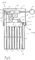
- FIG. 1 shows a schematic representation of a portable padlock 11, which is designed as an articulated lock 12 and has a lock body 13 and a flexible bracket 17, which is designed as an articulated rod bracket 18.
- This articulated rod bracket 18 has a plurality of articulated rods 39 which are pivotably connected to one another via respective rivets 41, with the articulated rod 39, which forms a second end 33 of the articulated rod bracket 18, being permanently attached to the lock body 13 or a housing 63 of the articulated lock 12 by means of a connecting rivet 43 .
- This housing 63 can be made of metal, for example, and serves in particular to protect the components arranged inside the lock body 13 .
- the first end 19 of the articulated rod bracket 18, on the other hand, can be locked on the lock body 13 or released from the lock body 13 and has a locking section 45, which can be inserted into the lock body 13 or the interior of the housing 63 to lock the first end 19.
- a locking mechanism 15 is arranged inside the housing 63 in order to lock the locking section 45 introduced into the lock body 13 and thus the first end 19 thereon.
- This has a bolt 37 which is designed to lock the inserted locking section 45 in a locking position on the lock body 13 and to release it in a release position for detachment from the lock body 13 .
- the bolt 37 can be moved into the locking position or into the release position by means of a key 38, with which a user can rotate a lock cylinder 61 and lock the inserted locking section 45 on the lock body 13 or release it for release.
- a jointed lock 12 can be configured with an electromechanical locking mechanism which has an electric motor for driving the bolt 37 in order to selectively move the bolt 37 into the locking position or the release position .
- the locking mechanism 15 can also be designed as a combination locking mechanism, on which a user can set a locking code in order to release a bolt 37 that is in the locking position for movement into the release position and to be able to release the inserted locking section 45 of the articulated rod bracket 18 from the lock body 13 .
- the lock body 13 comprises an alarm device 21 which is arranged within the housing 63 and has an acceleration sensor 35 and an acoustic signal transmitter 23 (eg piezo signal transmitter).
- the acceleration sensor 35 can be configured in particular as a vibration sensor in order to detect vibrations or other movements relative to the gravitational acceleration that the articulated lock 12 experiences during any attempted break-in and thereby be able to recognize such attempts. If an attempted break-in is detected by the acceleration sensor 35, the alarm device 21 can do this be designed to emit an acoustically perceptible alarm signal by means of the acoustic signal transmitter 23 in response to a detection signal from the acceleration sensor 35 .
- a sound outlet opening 25 is formed on the surface 31 of the lock body 13 on the side of the lock body 13 facing the articulated rod bracket 18, which is connected to the acoustic signal transmitter via a sound guide channel 27 23 communicated.
- the sound guide channel 27 is formed by an elongated, peripherally closed recess in a housing wall of the lock body 13 .
- the sound-guiding channel 27 is straight and can be designed, for example, as a bore in the housing 63 so that the sound-guiding channel 27 extends along a sound-guiding axis S.
- the acoustic signal generator 23 is arranged in a straight line or in alignment with the sound guide channel 27, so that the sound guide axis S also intersects it.
- This sound guide channel 27, which is necessary for sending out the alarm signal can now basically offer the possibility of penetrating the lock body 13 with a straight object such as a screwdriver and in particular of damaging the acoustic signal transmitter 23 in order to disable the alarm device 21 in the event of an attempt to break in.
- the sound guide channel 27 is aligned in such a way that its straight extension V, which runs parallel or collinear to the sound guide axis S, intersects a cover section 29 of the articulated rod bracket 18. which of the fixed with the lock body 13 or its housing 63 connected to the second end 33 of the articulated rod bracket 18 is formed.
- This cover section 29 of the articulated rod bracket 18 extends along a cover section extension axis A, which is aligned perpendicularly to the surface 31 of the lock body 13 on which the sound outlet opening 25 is formed.
- the sound guide channel 27 is oriented in such a way that the sound guide axis S intersects both the surface 31 of the lock body 13 and the cover section extension axis A of the cover section 29 at an angle of approximately 45°.
- the sound outlet opening 25 can be configured with a relatively short length in order to connect the sound outlet opening 25 formed on the outside of the housing 63 to the acoustic signal transmitter arranged in the interior of the housing 63, without the housing 63 having to be extended by the length necessary to form the sound guide channel 27 Bore experiences a significant weakening.
- cover section 29 of the articulated rod bracket 18 is formed on the second end 33, which is permanently connected to the lock body 13, it can be ensured that the straight-line extension V of the sound guide channel 27 reliably intersects the cover section extension axis A and an intervention in the sound guide channel 27 through the cover portion 29 at all times is blocked.
- a rectilinear intervention in the sound guide channel 27 can be prevented by blocking its rectilinear extension V by the cover section 29 arranged outside of the lock body 13 when the articulated rod bracket 18 is locked on the lock body 13 or the locking section 45 in the lock body 13 is introduced.
- the acoustic signal transmitter 23 it can be provided that it is arranged outside the alignment of the sound guide channel 27 and communicates with the sound outlet opening 25 via a connecting channel that opens into the sound guide channel 27 .
- a detection sensor 51 is arranged inside the lock body 13 and is designed to detect the insertion of the locking section 45 into the lock body 13 and to transmit a corresponding detection signal to a control device 49 .
- This control device 49 is designed to control the alarm device 21 and it can be provided in particular that the control device 49 activates and/or deactivates the alarm device 21 as a function of the detection signal from the detection sensor 51 .
- the control device 49 is also connected to a radio module 47, which is designed to wirelessly transmit an alarm signal generated by the alarm device 21, for example via a cellular connection, a WiFi/WLAN connection or a Bluetooth connection, to a user.
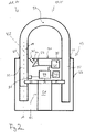
- FIG. 2 shows a schematic representation of a portable padlock 11, which is designed as a U-padlock 14 and has a lock body 13 and bracket 17, which is designed as a rigid and essentially U-shaped U-bolt 20.
- This U-bracket 20 has a short leg 53 and a long leg 55 which are straight and connected to one another via a curved connecting section 57 .
- the legs 53 and 55 are inserted into the respective insertion openings 65 and 67 of the lock body 13 and are locked on the lock body 13 by the bolts 37 assigned to the insertion openings 65 and 67 .
- the U-bolt 20 it is possible for the U-bolt 20 to be completely detachable from the lock body 13, while it can also be provided that only the short leg 63 can be removed from the lock body 13, while the long leg 55 is permanently in the lock body 13 remains.
- This can make it possible, for example, to hold the U-bolt 20 permanently on the lock body 13 and to pivot the U-bolt 20 about the long limb 55 after the short limb 53 has been detached from the lock body 13, for example by to guide the eyelet of a hasp.
- the short leg 53 can then be inserted into the insertion opening 65 after the U-bolt 20 has been pivoted back and locked by means of the bolt 37 .
- the bars 37 are parts of a locking mechanism 15 which is designed here as an electromechanical locking mechanism 15 and has an electric motor 59 .
- the electric motor 59 is designed to selectively move the bolt 37 into a locking position, in which the associated legs 53 or 55 of the U-bolt 20 are locked on the lock body 13, or to move it into a release position, in which the leg 53 or possibly the leg 55 can be detached from the lock body 13 or are.
- the locking mechanism 15 has a lock cylinder 61 which can be rotated by means of a key (not shown) so that a user can bring the bolt 37 into the desired position even without activating the electric motor 59 .
- This makes it possible to selectively lock the U-bolt 20 on the lock body 13 or to release it from it when an electrical energy source (not shown) for operating the electric motor 59 has already been used up and may need to be charged.
- An alarm device 21 with an acceleration sensor 35 and an acoustic signal transmitter 23 is again arranged inside the lock body 13 or its housing 63, by means of which an acoustically perceptible alarm signal can be generated and transmitted.
- the acoustic signal generator 23 communicates via a sound guide channel 27 extending in a straight line along a sound guide axis S with a sound outlet opening 25 which is formed on a surface 31 of the lock body 13 or its housing 63 facing the U-bolt 20 .
- a control device 49 is also provided, which is connected to the alarm device 21 and is designed to control it.
- the control device 49 is connected to a detection sensor 51, by means of which the insertion of the short leg 53 into the lock body 13 can be detected, so that the control device 49 can be configured to activate the alarm device 21 as a function of a detection signal from the detection sensor 51.
- the control device 49 is connected to a radio module 47, which is designed for wireless transmission of an alarm signal.
- a user can send control commands for the electric motor 59 to the radio module 47, wherein the control device 49 can be designed to control the electric motor 59 in response to the commands received.
Landscapes
- Lock And Its Accessories (AREA)
- Emergency Alarm Devices (AREA)
Claims (9)
- Antivol à étrier portable (11) comprenant un corps d'antivol (13) abritant un mécanisme de verrouillage (15), et un étrier flexible ou rigide (17),dans lequell'étrier (17) présente une première extrémité (19) qui peut être sélectivement verrouillée sur le corps d'antivol (13) au moyen du mécanisme de verrouillage (15), ou être libérée du corps d'antivol (13), etle corps d'antivol (13) comprend un dispositif d'alarme (21) présentant un générateur de signal acoustique (23) pour émettre un signal d'alarme perceptible acoustiquement, et au moins une ouverture de sortie du son (25) qui communique avec le générateur de signal acoustique (23) via un canal de guidage du son (27),l'étrier (17) présente au moins une portion de recouvrement (29) qui est formée par une portion de l'étrier (17) qui est adjacente au corps d'antivol (13) lorsque l'étrier (17) est verrouillé sur le corps d'antivol (13),le canal de guidage du son (27) est orienté de telle sorte que la portion de recouvrement (29) de l'étrier (17) est disposée dans le prolongement rectiligne (V) du canal de guidage du son (27) lorsque l'étrier (17) est verrouillé sur le corps d'antivol (13),le canal de guidage du son (27) s'étend le long d'un axe de guidage du son (S) en direction de l'ouverture de sortie du son (25), l'axe de guidage du son (S) coupant la portion de recouvrement (29) de l'étrier (17) lorsque l'étrier (17) est verrouillé sur le corps d'antivol (13),caractérisé en ce quel'axe de guidage du son (S) coupe une surface (31) du corps d'antivol (13) tournée vers l'étrier (17) selon un angle aigu.
- Antivol à étrier portable (11) selon la revendication 1,
dans lequel l'axe de guidage du son (S) coupe la surface (31) du corps d'antivol (13) tournée vers l'étrier (17) selon un angle compris entre 30° et 60°. - Antivol à étrier portable (11) selon la revendication 1 ou 2,
dans lequel la portion de recouvrement (29) de l'étrier (17) est orientée perpendiculairement à la surface (31) du corps d'antivol (13) au voisinage de l'ouverture de sortie du son (25) lorsque l'étrier (17) est verrouillé sur le corps d'antivol (13). - Antivol à étrier portable (11) selon l'une des revendications précédentes, dans lequel le générateur de signal acoustique (23) est disposé en dehors de l'alignement du canal de guidage du son (27).
- Antivol à étrier portable (11) selon l'une des revendications précédentes, dans lequel le dispositif d'alarme (21) comprend un capteur d'accélération (35).
- Antivol à étrier portable (11) selon l'une des revendications précédentes, dans lequel le mécanisme de verrouillage (15) comprend au moins un verrou (37) et un moteur électrique (59) pour entraîner le verrou (37), le verrou (37) étant réalisé pour, dans une position de verrouillage, verrouiller au moins la première extrémité (19) de l'étrier (17) sur le corps d'antivol (13) et, dans une position de libération, libérer au moins la première extrémité (19) de l'étrier (17) pour qu'elle se détache du corps d'antivol (13).
- Antivol à étrier portable (11) selon l'une des revendications précédentes, dans lequel l'étrier (17) comprend une deuxième extrémité (33) qui est reliée de manière permanente au corps d'antivol (13), la deuxième extrémité (33) formant la portion de recouvrement (29).
- Antivol à étrier portable (11) selon l'une des revendications 1 à 6,dans lequel l'antivol à étrier portable (11) est réalisé sous forme d'antivol à articulation (12), et l'étrier (17) est réalisé sous forme d'étrier à barres articulées (18) qui présente plusieurs barres articulées (39) reliées entre elles de manière pivotante,à la première extrémité (19), l'étrier à barres articulées (18) présente une portion de verrouillage (45) qui peut être sélectivement insérée dans le corps d'antivol (13) et être verrouillée sur le corps d'antivol (13) ou être détachée du corps d'antivol (13), etl'étrier à barres articulées (18) présente une deuxième extrémité (33) qui est fixée de manière permanente au corps d'antivol (13).
- Antivol à étrier portable (11) selon l'une des revendications 1 à 6, dans lequel l'antivol à étrier portable (11) est réalisé sous forme de cadenas à étrier en U (14), et l'étrier (17) est réalisé sous forme d'étrier en U (20) rigide, sensiblement en forme de U, qui présente deux branches rectilignes (53, 55) et une portion de liaison (57) reliant les branches (53, 55), la portion de recouvrement (29) de l'étrier (17) étant disposée sur l'une des branches (53, 55).
Applications Claiming Priority (1)
| Application Number | Priority Date | Filing Date | Title |
|---|---|---|---|
| DE102019123469.7A DE102019123469A1 (de) | 2019-09-02 | 2019-09-02 | Tragbares Bügelschloss |
Publications (2)
| Publication Number | Publication Date |
|---|---|
| EP3786397A1 EP3786397A1 (fr) | 2021-03-03 |
| EP3786397B1 true EP3786397B1 (fr) | 2022-06-29 |
Family
ID=72240296
Family Applications (1)
| Application Number | Title | Priority Date | Filing Date |
|---|---|---|---|
| EP20192527.8A Active EP3786397B1 (fr) | 2019-09-02 | 2020-08-25 | Cadenas portable |
Country Status (3)
| Country | Link |
|---|---|
| EP (1) | EP3786397B1 (fr) |
| DE (1) | DE102019123469A1 (fr) |
| DK (1) | DK3786397T3 (fr) |
Families Citing this family (1)
| Publication number | Priority date | Publication date | Assignee | Title |
|---|---|---|---|---|
| USD1080354S1 (en) | 2024-01-12 | 2025-06-24 | Control Group Companies, LLC | Combination alarm tag |
Family Cites Families (9)
| Publication number | Priority date | Publication date | Assignee | Title |
|---|---|---|---|---|
| US4811578A (en) * | 1983-08-18 | 1989-03-14 | John F. Masoncup | Padlock with tamper-actuated audible and/or inaudible alarm |
| GB2276412B (en) * | 1993-03-22 | 1995-11-22 | Alan David Somerfield | Improvements relating to locks |
| JPH08270279A (ja) * | 1995-03-29 | 1996-10-15 | Ngk Spark Plug Co Ltd | 二輪車等の盗難防止装置 |
| DE10026701A1 (de) | 2000-05-30 | 2001-12-06 | Bremicker Soehne Kg A | Bügelschloß |
| US20080094192A1 (en) * | 2004-09-01 | 2008-04-24 | Kane Dutt | Lock Apparatus and Method of Use |
| DE202005014526U1 (de) * | 2005-09-14 | 2007-02-01 | ABUS August Bremicker Söhne KG | Bremsscheibenschloss |
| CN2856340Y (zh) * | 2006-01-10 | 2007-01-10 | 邓伦凯 | 摩托车报警钢管锁 |
| DE102016104674A1 (de) * | 2016-03-14 | 2017-09-14 | Nuloc Gmbh | Fahrradschloss mit einem Textilband, Bausatz und Verfahren zum Betreiben eines Fahrradschlosses |
| DE102017105031A1 (de) * | 2017-03-09 | 2018-09-13 | ABUS August Bremicker Söhne KG | Gelenkschloss mit Alarmeinrichtung |
-
2019
- 2019-09-02 DE DE102019123469.7A patent/DE102019123469A1/de active Pending
-
2020
- 2020-08-25 EP EP20192527.8A patent/EP3786397B1/fr active Active
- 2020-08-25 DK DK20192527.8T patent/DK3786397T3/da active
Also Published As
| Publication number | Publication date |
|---|---|
| EP3786397A1 (fr) | 2021-03-03 |
| DK3786397T3 (da) | 2022-08-01 |
| DE102019123469A1 (de) | 2021-03-04 |
Similar Documents
| Publication | Publication Date | Title |
|---|---|---|
| EP1558486B1 (fr) | Cadenas pour bicyclette | |
| EP3372762B1 (fr) | Cadenas à articulation pourvu de dispositif d'alarme | |
| EP3591147B1 (fr) | Serrure de deux roues ayant une fonction d'alarme | |
| DE102007035116A1 (de) | Gelenkstabschloss | |
| EP3947867B1 (fr) | Serrure électronique mobile | |
| EP3233615B1 (fr) | Dispositif antivol de cycle | |
| EP3575520A1 (fr) | Cadenas à arceau | |
| EP3786397B1 (fr) | Cadenas portable | |
| DE202014006369U1 (de) | Ringbügelschloss | |
| DE102019123481A1 (de) | Gelenkschloss | |
| EP1856355B1 (fr) | Fenetre ou porte | |
| DE29515211U1 (de) | Schloß für gegen Einbruch, Aufbruch und/oder Manipulationen zu sichernde Türen | |
| DE102010021104B3 (de) | Digitales Hangschloss | |
| EP4306393A1 (fr) | Serrure de cadre | |
| EP4400679B1 (fr) | Cadenas électronique | |
| DE102024124406A1 (de) | Sicherungsvorrichtung und Schloss | |
| EP4200502B1 (fr) | Cadenas portatif | |
| EP1762999B1 (fr) | Dispositif de fixation | |
| DE4244295C1 (de) | Sicherheitsvorrichtung für eine Sicherheitstür | |
| WO2025224183A1 (fr) | Verrou de manille | |
| DE102011113771A1 (de) | Schlaufenschloss | |
| WO2025016625A1 (fr) | Couvercle pour un évidement de fraisage, formé dans un cadre de porte, pour recevoir un verrou de fermeture d'une serrure de porte | |
| DE102021116256A1 (de) | Sicherungssystem | |
| WO2025172216A1 (fr) | Verrou à fil de verrouillage flexible | |
| EP4717567A1 (fr) | Serrure de cadre électronique |
Legal Events
| Date | Code | Title | Description |
|---|---|---|---|
| PUAI | Public reference made under article 153(3) epc to a published international application that has entered the european phase |
Free format text: ORIGINAL CODE: 0009012 |
|
| STAA | Information on the status of an ep patent application or granted ep patent |
Free format text: STATUS: THE APPLICATION HAS BEEN PUBLISHED |
|
| AK | Designated contracting states |
Kind code of ref document: A1 Designated state(s): AL AT BE BG CH CY CZ DE DK EE ES FI FR GB GR HR HU IE IS IT LI LT LU LV MC MK MT NL NO PL PT RO RS SE SI SK SM TR |
|
| AX | Request for extension of the european patent |
Extension state: BA ME |
|
| STAA | Information on the status of an ep patent application or granted ep patent |
Free format text: STATUS: REQUEST FOR EXAMINATION WAS MADE |
|
| 17P | Request for examination filed |
Effective date: 20210816 |
|
| RBV | Designated contracting states (corrected) |
Designated state(s): AL AT BE BG CH CY CZ DE DK EE ES FI FR GB GR HR HU IE IS IT LI LT LU LV MC MK MT NL NO PL PT RO RS SE SI SK SM TR |
|
| GRAP | Despatch of communication of intention to grant a patent |
Free format text: ORIGINAL CODE: EPIDOSNIGR1 |
|
| STAA | Information on the status of an ep patent application or granted ep patent |
Free format text: STATUS: GRANT OF PATENT IS INTENDED |
|
| RIC1 | Information provided on ipc code assigned before grant |
Ipc: E05B 45/06 20060101ALN20211205BHEP Ipc: E05B 71/00 20060101ALI20211205BHEP Ipc: E05B 45/00 20060101AFI20211205BHEP |
|
| INTG | Intention to grant announced |
Effective date: 20220111 |
|
| GRAS | Grant fee paid |
Free format text: ORIGINAL CODE: EPIDOSNIGR3 |
|
| GRAA | (expected) grant |
Free format text: ORIGINAL CODE: 0009210 |
|
| STAA | Information on the status of an ep patent application or granted ep patent |
Free format text: STATUS: THE PATENT HAS BEEN GRANTED |
|
| AK | Designated contracting states |
Kind code of ref document: B1 Designated state(s): AL AT BE BG CH CY CZ DE DK EE ES FI FR GB GR HR HU IE IS IT LI LT LU LV MC MK MT NL NO PL PT RO RS SE SI SK SM TR |
|
| REG | Reference to a national code |
Ref country code: CH Ref legal event code: EP |
|
| REG | Reference to a national code |
Ref country code: AT Ref legal event code: REF Ref document number: 1501463 Country of ref document: AT Kind code of ref document: T Effective date: 20220715 |
|
| REG | Reference to a national code |
Ref country code: IE Ref legal event code: FG4D Free format text: LANGUAGE OF EP DOCUMENT: GERMAN |
|
| REG | Reference to a national code |
Ref country code: DE Ref legal event code: R096 Ref document number: 502020001296 Country of ref document: DE |
|
| REG | Reference to a national code |
Ref country code: DK Ref legal event code: T3 Effective date: 20220726 |
|
| REG | Reference to a national code |
Ref country code: NL Ref legal event code: FP |
|
| REG | Reference to a national code |
Ref country code: SE Ref legal event code: TRGR |
|
| REG | Reference to a national code |
Ref country code: NO Ref legal event code: T2 Effective date: 20220629 |
|
| REG | Reference to a national code |
Ref country code: LT Ref legal event code: MG9D |
|
| PG25 | Lapsed in a contracting state [announced via postgrant information from national office to epo] |
Ref country code: LT Free format text: LAPSE BECAUSE OF FAILURE TO SUBMIT A TRANSLATION OF THE DESCRIPTION OR TO PAY THE FEE WITHIN THE PRESCRIBED TIME-LIMIT Effective date: 20220629 Ref country code: HR Free format text: LAPSE BECAUSE OF FAILURE TO SUBMIT A TRANSLATION OF THE DESCRIPTION OR TO PAY THE FEE WITHIN THE PRESCRIBED TIME-LIMIT Effective date: 20220629 Ref country code: FI Free format text: LAPSE BECAUSE OF FAILURE TO SUBMIT A TRANSLATION OF THE DESCRIPTION OR TO PAY THE FEE WITHIN THE PRESCRIBED TIME-LIMIT Effective date: 20220629 Ref country code: BG Free format text: LAPSE BECAUSE OF FAILURE TO SUBMIT A TRANSLATION OF THE DESCRIPTION OR TO PAY THE FEE WITHIN THE PRESCRIBED TIME-LIMIT Effective date: 20220929 |
|
| PG25 | Lapsed in a contracting state [announced via postgrant information from national office to epo] |
Ref country code: RS Free format text: LAPSE BECAUSE OF FAILURE TO SUBMIT A TRANSLATION OF THE DESCRIPTION OR TO PAY THE FEE WITHIN THE PRESCRIBED TIME-LIMIT Effective date: 20220629 Ref country code: LV Free format text: LAPSE BECAUSE OF FAILURE TO SUBMIT A TRANSLATION OF THE DESCRIPTION OR TO PAY THE FEE WITHIN THE PRESCRIBED TIME-LIMIT Effective date: 20220629 |
|
| PG25 | Lapsed in a contracting state [announced via postgrant information from national office to epo] |
Ref country code: SM Free format text: LAPSE BECAUSE OF FAILURE TO SUBMIT A TRANSLATION OF THE DESCRIPTION OR TO PAY THE FEE WITHIN THE PRESCRIBED TIME-LIMIT Effective date: 20220629 Ref country code: SK Free format text: LAPSE BECAUSE OF FAILURE TO SUBMIT A TRANSLATION OF THE DESCRIPTION OR TO PAY THE FEE WITHIN THE PRESCRIBED TIME-LIMIT Effective date: 20220629 Ref country code: RO Free format text: LAPSE BECAUSE OF FAILURE TO SUBMIT A TRANSLATION OF THE DESCRIPTION OR TO PAY THE FEE WITHIN THE PRESCRIBED TIME-LIMIT Effective date: 20220629 Ref country code: PT Free format text: LAPSE BECAUSE OF FAILURE TO SUBMIT A TRANSLATION OF THE DESCRIPTION OR TO PAY THE FEE WITHIN THE PRESCRIBED TIME-LIMIT Effective date: 20221031 Ref country code: ES Free format text: LAPSE BECAUSE OF FAILURE TO SUBMIT A TRANSLATION OF THE DESCRIPTION OR TO PAY THE FEE WITHIN THE PRESCRIBED TIME-LIMIT Effective date: 20220629 Ref country code: EE Free format text: LAPSE BECAUSE OF FAILURE TO SUBMIT A TRANSLATION OF THE DESCRIPTION OR TO PAY THE FEE WITHIN THE PRESCRIBED TIME-LIMIT Effective date: 20220629 |
|
| PG25 | Lapsed in a contracting state [announced via postgrant information from national office to epo] |
Ref country code: PL Free format text: LAPSE BECAUSE OF FAILURE TO SUBMIT A TRANSLATION OF THE DESCRIPTION OR TO PAY THE FEE WITHIN THE PRESCRIBED TIME-LIMIT Effective date: 20220629 Ref country code: IS Free format text: LAPSE BECAUSE OF FAILURE TO SUBMIT A TRANSLATION OF THE DESCRIPTION OR TO PAY THE FEE WITHIN THE PRESCRIBED TIME-LIMIT Effective date: 20221029 |
|
| REG | Reference to a national code |
Ref country code: DE Ref legal event code: R097 Ref document number: 502020001296 Country of ref document: DE |
|
| PG25 | Lapsed in a contracting state [announced via postgrant information from national office to epo] |
Ref country code: MC Free format text: LAPSE BECAUSE OF FAILURE TO SUBMIT A TRANSLATION OF THE DESCRIPTION OR TO PAY THE FEE WITHIN THE PRESCRIBED TIME-LIMIT Effective date: 20220629 Ref country code: AL Free format text: LAPSE BECAUSE OF FAILURE TO SUBMIT A TRANSLATION OF THE DESCRIPTION OR TO PAY THE FEE WITHIN THE PRESCRIBED TIME-LIMIT Effective date: 20220629 |
|
| PG25 | Lapsed in a contracting state [announced via postgrant information from national office to epo] |
Ref country code: LU Free format text: LAPSE BECAUSE OF NON-PAYMENT OF DUE FEES Effective date: 20220825 Ref country code: CZ Free format text: LAPSE BECAUSE OF FAILURE TO SUBMIT A TRANSLATION OF THE DESCRIPTION OR TO PAY THE FEE WITHIN THE PRESCRIBED TIME-LIMIT Effective date: 20220629 |
|
| PLBE | No opposition filed within time limit |
Free format text: ORIGINAL CODE: 0009261 |
|
| STAA | Information on the status of an ep patent application or granted ep patent |
Free format text: STATUS: NO OPPOSITION FILED WITHIN TIME LIMIT |
|
| 26N | No opposition filed |
Effective date: 20230330 |
|
| PG25 | Lapsed in a contracting state [announced via postgrant information from national office to epo] |
Ref country code: IE Free format text: LAPSE BECAUSE OF NON-PAYMENT OF DUE FEES Effective date: 20220825 |
|
| PG25 | Lapsed in a contracting state [announced via postgrant information from national office to epo] |
Ref country code: SI Free format text: LAPSE BECAUSE OF FAILURE TO SUBMIT A TRANSLATION OF THE DESCRIPTION OR TO PAY THE FEE WITHIN THE PRESCRIBED TIME-LIMIT Effective date: 20220629 |
|
| PG25 | Lapsed in a contracting state [announced via postgrant information from national office to epo] |
Ref country code: IT Free format text: LAPSE BECAUSE OF FAILURE TO SUBMIT A TRANSLATION OF THE DESCRIPTION OR TO PAY THE FEE WITHIN THE PRESCRIBED TIME-LIMIT Effective date: 20220629 |
|
| PG25 | Lapsed in a contracting state [announced via postgrant information from national office to epo] |
Ref country code: CY Free format text: LAPSE BECAUSE OF FAILURE TO SUBMIT A TRANSLATION OF THE DESCRIPTION OR TO PAY THE FEE WITHIN THE PRESCRIBED TIME-LIMIT Effective date: 20220629 |
|
| PG25 | Lapsed in a contracting state [announced via postgrant information from national office to epo] |
Ref country code: MK Free format text: LAPSE BECAUSE OF FAILURE TO SUBMIT A TRANSLATION OF THE DESCRIPTION OR TO PAY THE FEE WITHIN THE PRESCRIBED TIME-LIMIT Effective date: 20220629 Ref country code: HU Free format text: LAPSE BECAUSE OF FAILURE TO SUBMIT A TRANSLATION OF THE DESCRIPTION OR TO PAY THE FEE WITHIN THE PRESCRIBED TIME-LIMIT; INVALID AB INITIO Effective date: 20200825 |
|
| PG25 | Lapsed in a contracting state [announced via postgrant information from national office to epo] |
Ref country code: TR Free format text: LAPSE BECAUSE OF FAILURE TO SUBMIT A TRANSLATION OF THE DESCRIPTION OR TO PAY THE FEE WITHIN THE PRESCRIBED TIME-LIMIT Effective date: 20220629 |
|
| PG25 | Lapsed in a contracting state [announced via postgrant information from national office to epo] |
Ref country code: MT Free format text: LAPSE BECAUSE OF FAILURE TO SUBMIT A TRANSLATION OF THE DESCRIPTION OR TO PAY THE FEE WITHIN THE PRESCRIBED TIME-LIMIT Effective date: 20220629 |
|
| PG25 | Lapsed in a contracting state [announced via postgrant information from national office to epo] |
Ref country code: BG Free format text: LAPSE BECAUSE OF FAILURE TO SUBMIT A TRANSLATION OF THE DESCRIPTION OR TO PAY THE FEE WITHIN THE PRESCRIBED TIME-LIMIT Effective date: 20220629 |
|
| PG25 | Lapsed in a contracting state [announced via postgrant information from national office to epo] |
Ref country code: BG Free format text: LAPSE BECAUSE OF FAILURE TO SUBMIT A TRANSLATION OF THE DESCRIPTION OR TO PAY THE FEE WITHIN THE PRESCRIBED TIME-LIMIT Effective date: 20220629 |
|
| PG25 | Lapsed in a contracting state [announced via postgrant information from national office to epo] |
Ref country code: GR Free format text: LAPSE BECAUSE OF NON-PAYMENT OF DUE FEES Effective date: 20220629 |
|
| PG25 | Lapsed in a contracting state [announced via postgrant information from national office to epo] |
Ref country code: GR Free format text: LAPSE BECAUSE OF NON-PAYMENT OF DUE FEES Effective date: 20220629 |
|
| PGFP | Annual fee paid to national office [announced via postgrant information from national office to epo] |
Ref country code: NL Payment date: 20250821 Year of fee payment: 6 |
|
| PGFP | Annual fee paid to national office [announced via postgrant information from national office to epo] |
Ref country code: DK Payment date: 20250825 Year of fee payment: 6 |
|
| PGFP | Annual fee paid to national office [announced via postgrant information from national office to epo] |
Ref country code: NO Payment date: 20250826 Year of fee payment: 6 |
|
| PGFP | Annual fee paid to national office [announced via postgrant information from national office to epo] |
Ref country code: BE Payment date: 20250820 Year of fee payment: 6 Ref country code: GB Payment date: 20250820 Year of fee payment: 6 |
|
| PGFP | Annual fee paid to national office [announced via postgrant information from national office to epo] |
Ref country code: AT Payment date: 20250821 Year of fee payment: 6 Ref country code: FR Payment date: 20250828 Year of fee payment: 6 |
|
| PGFP | Annual fee paid to national office [announced via postgrant information from national office to epo] |
Ref country code: CH Payment date: 20250901 Year of fee payment: 6 Ref country code: SE Payment date: 20250820 Year of fee payment: 6 |
|
| PGFP | Annual fee paid to national office [announced via postgrant information from national office to epo] |
Ref country code: DE Payment date: 20251029 Year of fee payment: 6 |