EP3786397B1 - Portable padlock - Google Patents
Portable padlock Download PDFInfo
- Publication number
- EP3786397B1 EP3786397B1 EP20192527.8A EP20192527A EP3786397B1 EP 3786397 B1 EP3786397 B1 EP 3786397B1 EP 20192527 A EP20192527 A EP 20192527A EP 3786397 B1 EP3786397 B1 EP 3786397B1
- Authority
- EP
- European Patent Office
- Prior art keywords
- hoop
- lock body
- lock
- portable
- sound
- Prior art date
- Legal status (The legal status is an assumption and is not a legal conclusion. Google has not performed a legal analysis and makes no representation as to the accuracy of the status listed.)
- Active
Links
Images
Classifications
-
- E—FIXED CONSTRUCTIONS
- E05—LOCKS; KEYS; WINDOW OR DOOR FITTINGS; SAFES
- E05B—LOCKS; ACCESSORIES THEREFOR; HANDCUFFS
- E05B45/00—Alarm locks
- E05B45/005—Chain-locks, cable-locks or padlocks with alarms
-
- E—FIXED CONSTRUCTIONS
- E05—LOCKS; KEYS; WINDOW OR DOOR FITTINGS; SAFES
- E05B—LOCKS; ACCESSORIES THEREFOR; HANDCUFFS
- E05B71/00—Locks specially adapted for bicycles, other than padlocks
-
- E—FIXED CONSTRUCTIONS
- E05—LOCKS; KEYS; WINDOW OR DOOR FITTINGS; SAFES
- E05B—LOCKS; ACCESSORIES THEREFOR; HANDCUFFS
- E05B45/00—Alarm locks
- E05B45/06—Electric alarm locks
- E05B2045/065—Switch or sensor type used in alarm locks
Definitions
- the invention relates to a portable shackle lock with a lock body that houses a locking mechanism and with a flexible or rigid shackle, the shackle having a first end which can be locked by the locking mechanism or released from the lock body, and the lock body has an alarm device with an acoustic signal transmitter for outputting an acoustically perceptible alarm signal and has at least one sound outlet opening which communicates with the acoustic signal transmitter via a sound guide channel.
- the shackle of such a portable shackle lock is generally used to grasp and secure an object or to connect a first object to a second object.
- a shackle can first be guided through a section of a bicycle, for example a frame section, and around a stationary object such as a bicycle stand, whereupon the first end can be locked on the lock body so that the bicycle can be driven through the loop formed by the bracket is securely connected to the bicycle stand.
- a two-wheeler can be secured against unauthorized driving away by a portable padlock, in that the loop formed by the bracket is guided through the spokes of one of the running wheels in such a way that movement of the latter is limited.
- Portable U-locks can also be used to securely lock doors, for example by passing the shackle through the eyelet of a hasp.
- a padlock Due to the possibility of carrying and moving such a padlock, it can be used flexibly at different locations and depending on the respective circumstances to secure different objects. For example, a user can choose in which way or on which section he connects the bracket to a bicycle or other object in order to secure it.
- the design of a portable padlock with an alarm device also makes it possible to detect attempts to break in and to draw the attention of a user or other people in the vicinity of the lock to this by means of an acoustically perceptible signal.
- a padlock is described, to the lock body of which an electronic device is attached by means of a strap and can be secured to the lock body by a shackle of the lock, which can be guided through a ring connected to the electronic device.
- An alarm device with a loudspeaker is arranged in the electronic device, it being possible for an acoustic signal to emerge from the electronic device through a number of openings.
- U.S. 4,811,578 A shows a padlock with an alarm device, in which a loudspeaker of the alarm device communicates with an insertion channel for a leg of a shackle of the padlock. This is intended to prevent a channel for sound conduction from becoming clogged in the course of an attempt to break open, with the leg being automatically ejected from the insertion channel by means of a spring as a result of an attempt to break open, in order to enable sound development.
- CN 2 856 340 Y a lock is also described, in the housing of which an alarm device with a loudspeaker is arranged.
- a locking device in order to be able to attach a bicycle to a carrier.
- the locking device has an alarm device with an alarm horn in order to be able to generate an acoustic alarm signal.
- a sound guide channel which opens into a sound outlet opening formed on an outside of the lock body.
- Such an open sound guide channel potentially harbors the risk of unauthorized access to the interior of the lock body, with damage to the acoustic signal generator and suppression of the alarm signal by inserting a straight and pointed object into the sound guide channel, such as a screwdriver, particularly in the course of attempts to break in or a nail, can be aimed for.
- the shackle of this shackle lock has at least one cover section, which is covered by one adjacent to the lock body
- Section of the shackle locked to the lock body is formed, and the sound guide channel is oriented such that the cover portion of the shackle is arranged in a linear extension of the sound guide channel when the shackle is locked to the lock body.
- the invention thus relates in a general manner to a portable padlock with a lock body housing a locking mechanism and with a flexible or rigid shackle, the shackle having a first end which can be locked by the locking mechanism or released from the lock body, and wherein the lock body comprises an alarm device with an acoustic signal generator for emitting an acoustically perceptible alarm signal and has at least one sound outlet opening which communicates with the acoustic signal generator via a sound guide channel, wherein the shackle has at least one cover section which is covered by a section of the is formed on the shackle locked on the lock body, with the sound guide channel being aligned in such a way that the cover section of the shackle is arranged in a straight line extension of the sound guide duct when the shackle is attached to the S lock body is locked.
- a portable padlock designed with a shackle that is flexible in sections can be embodied as a so-called articulated lock, the shackle of which has a plurality of articulated rods that are pivotably connected to one another.
- the basic structure of such a joint lock with an alarm device can be, for example DE 10 2017 105 031 A1 be removed.
- such a padlock can be designed as a so-called U-padlock, which has a rigid and essentially U-shaped bracket with two legs, one of which at least one can be selectively locked on the lock body or can be detached from it.
- U-padlock which has a rigid and essentially U-shaped bracket with two legs, one of which at least one can be selectively locked on the lock body or can be detached from it.
- the general structure of a U-bolt padlock and how it works is shown, for example, in EP 1 160 405 A1 described, the lock shown there having no alarm device. Basically, however, an alarm device as in the above DE 10 2017 105 031 A1 can also be used with a U-bolt padlock.
- a flexible shackle of a portable padlock as a rope shackle, in particular as a wire rope shackle, or as a chain shackle, which has a block at least at a first end, which can be locked on the lock body or released from the lock body.
- a block can be locked in particular in the same or similar manner as locking a leg of a U-bolt.
- the shackle has a cover section which is arranged outside the lock body and forms a part of the shackle located in the vicinity of the surface of the lock body when it is locked to the lock body.
- the cover section of the shackle is thus not located at an end of the shackle that is remote from the lock body.
- Said cover section can in particular be formed by a longitudinal extension section of the shackle, which protrudes perpendicularly or obliquely from the lock body at least when the shackle is locked on the lock body.
- the cover section can differ from other sections of the shackle in particular in that the cover section extends at least essentially uniformly, starting from the surface of the lock body.
- a straight cover section of the bracket can thus run in the same direction, while a curved cover section can have a substantially constant radius.
- a cover section of the shackle By arranging the cover section of the shackle in a straight line extension of the sound duct when the shackle is locked on the lock body, straight access into the sound duct can be blocked by the cover section and violent intervention into the sound duct or through the sound duct can be made using a straight object , for example a screwdriver, can be prevented.
- a straight object for example a screwdriver
- an acoustic signal transmitter arranged at one end of a straight sound guide channel can be protected against such interventions.
- the sound guide channel can run in a straight line, for example as a bore in a housing of the lock, or curved, in particular curved in sections.
- the straight extension mentioned relates to the alignment of the sound guide channel immediately before its transition into the sound outlet opening.
- the cover section is formed by a rigid element of the bracket, even if the bracket can in principle be flexible.
- the cover section can be formed by a section of an individual jointed rod of a jointed-rod bracket or by a section of a block of a chain-like or rope-like bracket that protrudes beyond the lock body in the locked state.
- the sound outlet opening can in particular be arranged on the lock body in such a way that its distance from the cover section along the straight extension of the sound guide channel is as small as possible in order to prevent intervention in to complicate the sound guide channel.
- at least a certain intermediate space or air gap must be kept free between the sound outlet opening on the outside of the lock body and the cover section of the shackle, in order to allow sound to escape from the sound outlet opening without significant damping or distortion, also in the direction of the cover section and in particular laterally in relation to the To allow surface of the lock body.
- the shackle can have a second end, which is either permanently connected to the lock body or permanently separated from the lock body or can likewise be optionally locked to the lock body by means of the locking mechanism or can be released from the lock body.
- both ends of the shackle can be detachable from the lock body so that the entire shackle can be separated from the lock body and passed through a portion of an object to be secured, after which both ends can be locked to the lock body.
- the second end can be permanently attached to the lock body, so that a user can guide the shackle, starting from the first end, through an object to be secured and then only has to connect the first end to the lock body for locking, while there is a permanent connection between the lock body and the bracket over the second end thereof. Provision can also be made for the second end of the shackle to be permanently separated from the lock body and, for example, to form a closed loop.
- the cover section can be provided at the first end of the shackle and/or at the second end of the shackle, provided that the second end of the shackle is connected to the lock body at least when the shackle is locked to it. Regardless of the respective end of the bracket which has the cover section, it can be achieved that the sound guide channel extends in a straight line out of the sound outlet opening is blocked by the cover portion of the shackle when locked to the lock body.
- the first end of the shackle can have a locking section which can optionally be inserted into the lock body or can be detached from the lock body, with the second end of the shackle optionally also having a locking section which can optionally be inserted into the lock body or can be detached from the lock body.
- the locking mechanism can be designed to either lock the locking section of the first end of the shackle inserted into the lock body and optionally also the locking section of the second end of the shackle inserted into the lock body on the lock body or release it for release from the lock body.
- the cover section of the bracket can directly adjoin the locking section of the first end of the bracket or possibly the locking section of the second end of the bracket.
- the cover section of the shackle can thus extend directly from the surface of the lock body, so that a small distance can be achieved between the sound outlet opening and the cover section of the shackle in a straight line extension of the sound guide channel.
- a respective locking section can be formed in particular at the respective ends, which in the lock body can be inserted and the locking mechanism can in particular comprise one or two bolts, by means of which the respective ends of the shackle which can be inserted into the lock body can be locked thereon selectively and independently of one another.
- the sound guide channel extends along a sound guide axis in the direction of the sound outlet opening, with the sound guide axis intersecting the cover section of the shackle when the shackle is locked on the lock body.
- the sound outlet opening and the sound guide channel can be formed in a simple manner by a bore which, starting from a surface of the lock body, can extend in a straight line along the sound guide axis through a housing of the lock body to an acoustic signal transmitter arranged inside the lock body.
- such a sound guide axis does not necessarily have to intersect the acoustic signal generator; Rather, it is possible for the acoustic signal generator to be arranged outside the alignment of the sound guide channel and to communicate with the sound guide channel via a connecting channel.
- the cover portion of the shackle may extend along a straight cover portion axis of extension, wherein the sound guide axis intersects the cover portion axis of extension when the shackle is locked to the lock body.
- the cover section of the bracket can extend in a straight line along the axis of extension of the cover section and in particular perpendicularly to a surface of the lock body on which the sound outlet opening is formed. Furthermore, the sound guide axis can intersect the cover section extension axis at a small distance from the surface of the lock body, so that a straight-line engagement in the sound guide channel through the sound outlet opening is reliably blocked by the cover section of the bracket.
- angles between 30° and 60° can be provided. This enables a small distance between the sound outlet opening and the cover section in the direction of the sound guide axis, so that a straight-line intervention in the sound guide channel can be reliably counteracted. Equally, a sufficient free space or air gap between the sound outlet opening and the cover section can still remain in the stated angular range in order to achieve trouble-free exit of a generated alarm signal without significant damping or distortion.
- the sound guide axis can intersect the axis of extension of the cover section at an angle of approximately 45°.
- the sound guide axis intersects a surface of the lock body facing the shackle at an acute angle, in particular at an angle of between 30° and 60°.
- the sound guide axis can intersect a surface of the lock body facing the shackle, in particular at an angle of about 45°, with a small straight distance between the sound outlet opening along the sound guide axis and a cover section of the shackle extending, for example, perpendicular to the surface of the lock body, with simultaneous undisturbed Development of an alarm signal generated can be achieved.
- a peripheral border of the sound outlet opening on the surface of the lock body can extend within a surface plane of extent, the sound guide axis the surface plane of extent in one can cut acute angles, in particular at an angle between 30° and 60°.
- the sound outlet opening can be arranged at such angles of intersection at a small distance in the straight line extension of the sound guide channel to the cover section of the bracket.
- the sound guide channel can be designed with a relatively small length, in particular at an angle between the sound guide axis and the surface extension plane of about 45°, in order to lead, for example, from an outside of a housing into its interior and to the acoustic signal generator. A possible weakening of the housing due to a long bore to form the sound guide channel can thus be avoided.
- angles or angle ranges mentioned relate in principle to the dimension that can be achieved within the scope of manufacturing tolerances or manufacturing inaccuracies.
- the cover portion of the shackle may be oriented perpendicular to the surface of the lock body in the vicinity of the sound exit opening when the shackle is locked to the lock body.
- a sound guide axis, along which the sound guide channel extends can intersect the surface of the lock body or a surface extension plane and the cover section of the bracket at an angle of approximately 45°.
- the acoustic signal transmitter can be arranged outside the alignment of the sound guide channel.
- the acoustic signal generator via a connecting channel with the sound guide channel and according to the Communicate sound outlet opening, both the sound guide channel and the connecting channel can be designed as bores.
- Such an arrangement of the acoustic signal transmitter outside the alignment of the sound guide channel can also ensure that the acoustic signal transmitter cannot be reached and damaged by a straight object inserted into the sound guide channel.
- by blocking the linear extension of the sound duct with the cover portion of the shackle tampering with the sound duct and possible damage to the portable padlock or components located inside the lock body can be prevented.
- the shackle may have a second end permanently connected to the latch body, the second end forming the cover portion.
- the U-shaped padlock of such a lock can be designed with two legs of different lengths, with the long leg remaining permanently in the lock body and only the short leg being detachable from the lock body is. This can make it possible to pivot the U-bolt about the long leg, so that the U-bolt can be guided through an object starting from the short leg, without the shackle having to be completely detached from the lock body.
- one of the articulated rods of the articulated rod bracket can also be made for one of the articulated rods of the articulated rod bracket to be permanently attached to the lock body (rigid or articulated), so that a user only guides the free first end through an object to be secured and into the locking device Lock body must introduce.
- the alarm device can have an acceleration sensor.
- an acceleration sensor can be configured as a vibration sensor, by means of which vibrations that the portable padlock typically experiences during an attempted break-in can be detected. This makes it possible to detect attempts to break out and then to trigger an acoustically perceptible alarm signal.
- the lock body can have a control device which is designed to control the alarm device.
- the control device can be designed to activate or deactivate the alarm device in order to prevent an unwanted alarm signal from being triggered, for example.
- Portable U-locks can often be transported between different locations, for example between locations where a two-wheeler is secured, with vibrations often occurring during such transport, as a result of which an unwanted and annoying alarm can be triggered.
- an unwanted triggering of an alarm can be prevented by deactivating the alarm device before transport.
- the control device can be connected to a sensor which is designed to detect the optional insertion of the first end of the shackle or a locking section formed thereon into the lock body and to generate a corresponding detection signal and/or the optional insertion of a second end of the shackle and a locking portion formed thereon and to generate a corresponding detection signal.
- This grasping of the respective end of the bracket can take place directly or indirectly (eg via an additional actuating element).
- the control device can be designed to activate and/or deactivate the alarm device depending on the detection signal.
- the lock body can have a radio module which is designed to wirelessly transmit an alarm signal emitted by the alarm device and/or which is designed to wirelessly receive a control command for the locking mechanism.
- the locking mechanism can include at least one bolt and an electric motor for driving the bolt, the bolt being designed to lock at least the first end of the shackle to the lock body in a locking position and to lock at least the first end of the shackle to the lock body in a release position release from the lock body.
- a locking mechanism is consequently designed as an electromechanical locking mechanism.
- the locking mechanism can comprise at least one bolt and a lock cylinder for driving the bolt, with the bolt being designed to hold at least the first end of the shackle inserted into the lock body in a locking position to lock on the lock body and release in a release position for loosening of the lock body.
- a lock cylinder can be rotated by means of a key in order to move the bolt or bolts either into the locking position or the release position.
- the locking mechanism of a portable padlock as a combination locking mechanism which has a number of code rings on which a user can set a locking code in order to release a bolt for movement from the locking position into the release position.
- the lock body may include an electrical power source for providing electrical power.
- This electrical energy source can be used in particular to supply electrical energy to the alarm device or its components and, if applicable, the components of an electromechanical locking mechanism.
- the lock body can have a housing and the sound guide channel can be formed by a bore in the housing. This makes it possible to form a sound guide channel extending along a sound guide axis in a simple manner, with the housing being able to serve to protect the components arranged inside the lock body and in particular the locking mechanism and the alarm device from external access.
- the housing can be made of metal and, for example, as a cast part.
- the portable shackle lock can be designed as a joint lock and the shackle can be designed as an articulated bar shackle which has a plurality of articulated bars pivotably connected to one another, the articulated bar shackle having a locking section at the first end which can be selectively inserted into the lock body and locked to the lock body or is detachable from the latch body, and wherein the toggle bar shackle has a second end permanently attached to the latch body.
- the cover section of the bracket can be provided in particular on the articulated rod that forms the first end of the articulated rod bracket, or on the articulated rod that forms the second end of the articulated rod bracket.
- the portable padlock may be configured as a U-bolt padlock and the shackle may be configured as a rigid, generally U-shaped U-bolt having two straight legs and one the connecting portion connecting the legs, wherein the cover portion of the bracket is arranged on one of the legs.
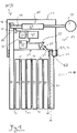
- FIG. 1 shows a schematic representation of a portable padlock 11, which is designed as an articulated lock 12 and has a lock body 13 and a flexible bracket 17, which is designed as an articulated rod bracket 18.
- This articulated rod bracket 18 has a plurality of articulated rods 39 which are pivotably connected to one another via respective rivets 41, with the articulated rod 39, which forms a second end 33 of the articulated rod bracket 18, being permanently attached to the lock body 13 or a housing 63 of the articulated lock 12 by means of a connecting rivet 43 .
- This housing 63 can be made of metal, for example, and serves in particular to protect the components arranged inside the lock body 13 .
- the first end 19 of the articulated rod bracket 18, on the other hand, can be locked on the lock body 13 or released from the lock body 13 and has a locking section 45, which can be inserted into the lock body 13 or the interior of the housing 63 to lock the first end 19.
- a locking mechanism 15 is arranged inside the housing 63 in order to lock the locking section 45 introduced into the lock body 13 and thus the first end 19 thereon.
- This has a bolt 37 which is designed to lock the inserted locking section 45 in a locking position on the lock body 13 and to release it in a release position for detachment from the lock body 13 .
- the bolt 37 can be moved into the locking position or into the release position by means of a key 38, with which a user can rotate a lock cylinder 61 and lock the inserted locking section 45 on the lock body 13 or release it for release.
- a jointed lock 12 can be configured with an electromechanical locking mechanism which has an electric motor for driving the bolt 37 in order to selectively move the bolt 37 into the locking position or the release position .
- the locking mechanism 15 can also be designed as a combination locking mechanism, on which a user can set a locking code in order to release a bolt 37 that is in the locking position for movement into the release position and to be able to release the inserted locking section 45 of the articulated rod bracket 18 from the lock body 13 .
- the lock body 13 comprises an alarm device 21 which is arranged within the housing 63 and has an acceleration sensor 35 and an acoustic signal transmitter 23 (eg piezo signal transmitter).
- the acceleration sensor 35 can be configured in particular as a vibration sensor in order to detect vibrations or other movements relative to the gravitational acceleration that the articulated lock 12 experiences during any attempted break-in and thereby be able to recognize such attempts. If an attempted break-in is detected by the acceleration sensor 35, the alarm device 21 can do this be designed to emit an acoustically perceptible alarm signal by means of the acoustic signal transmitter 23 in response to a detection signal from the acceleration sensor 35 .
- a sound outlet opening 25 is formed on the surface 31 of the lock body 13 on the side of the lock body 13 facing the articulated rod bracket 18, which is connected to the acoustic signal transmitter via a sound guide channel 27 23 communicated.
- the sound guide channel 27 is formed by an elongated, peripherally closed recess in a housing wall of the lock body 13 .
- the sound-guiding channel 27 is straight and can be designed, for example, as a bore in the housing 63 so that the sound-guiding channel 27 extends along a sound-guiding axis S.
- the acoustic signal generator 23 is arranged in a straight line or in alignment with the sound guide channel 27, so that the sound guide axis S also intersects it.
- This sound guide channel 27, which is necessary for sending out the alarm signal can now basically offer the possibility of penetrating the lock body 13 with a straight object such as a screwdriver and in particular of damaging the acoustic signal transmitter 23 in order to disable the alarm device 21 in the event of an attempt to break in.
- the sound guide channel 27 is aligned in such a way that its straight extension V, which runs parallel or collinear to the sound guide axis S, intersects a cover section 29 of the articulated rod bracket 18. which of the fixed with the lock body 13 or its housing 63 connected to the second end 33 of the articulated rod bracket 18 is formed.
- This cover section 29 of the articulated rod bracket 18 extends along a cover section extension axis A, which is aligned perpendicularly to the surface 31 of the lock body 13 on which the sound outlet opening 25 is formed.
- the sound guide channel 27 is oriented in such a way that the sound guide axis S intersects both the surface 31 of the lock body 13 and the cover section extension axis A of the cover section 29 at an angle of approximately 45°.
- the sound outlet opening 25 can be configured with a relatively short length in order to connect the sound outlet opening 25 formed on the outside of the housing 63 to the acoustic signal transmitter arranged in the interior of the housing 63, without the housing 63 having to be extended by the length necessary to form the sound guide channel 27 Bore experiences a significant weakening.
- cover section 29 of the articulated rod bracket 18 is formed on the second end 33, which is permanently connected to the lock body 13, it can be ensured that the straight-line extension V of the sound guide channel 27 reliably intersects the cover section extension axis A and an intervention in the sound guide channel 27 through the cover portion 29 at all times is blocked.
- a rectilinear intervention in the sound guide channel 27 can be prevented by blocking its rectilinear extension V by the cover section 29 arranged outside of the lock body 13 when the articulated rod bracket 18 is locked on the lock body 13 or the locking section 45 in the lock body 13 is introduced.
- the acoustic signal transmitter 23 it can be provided that it is arranged outside the alignment of the sound guide channel 27 and communicates with the sound outlet opening 25 via a connecting channel that opens into the sound guide channel 27 .
- a detection sensor 51 is arranged inside the lock body 13 and is designed to detect the insertion of the locking section 45 into the lock body 13 and to transmit a corresponding detection signal to a control device 49 .
- This control device 49 is designed to control the alarm device 21 and it can be provided in particular that the control device 49 activates and/or deactivates the alarm device 21 as a function of the detection signal from the detection sensor 51 .
- the control device 49 is also connected to a radio module 47, which is designed to wirelessly transmit an alarm signal generated by the alarm device 21, for example via a cellular connection, a WiFi/WLAN connection or a Bluetooth connection, to a user.
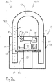
- FIG. 2 shows a schematic representation of a portable padlock 11, which is designed as a U-padlock 14 and has a lock body 13 and bracket 17, which is designed as a rigid and essentially U-shaped U-bolt 20.
- This U-bracket 20 has a short leg 53 and a long leg 55 which are straight and connected to one another via a curved connecting section 57 .
- the legs 53 and 55 are inserted into the respective insertion openings 65 and 67 of the lock body 13 and are locked on the lock body 13 by the bolts 37 assigned to the insertion openings 65 and 67 .
- the U-bolt 20 it is possible for the U-bolt 20 to be completely detachable from the lock body 13, while it can also be provided that only the short leg 63 can be removed from the lock body 13, while the long leg 55 is permanently in the lock body 13 remains.
- This can make it possible, for example, to hold the U-bolt 20 permanently on the lock body 13 and to pivot the U-bolt 20 about the long limb 55 after the short limb 53 has been detached from the lock body 13, for example by to guide the eyelet of a hasp.
- the short leg 53 can then be inserted into the insertion opening 65 after the U-bolt 20 has been pivoted back and locked by means of the bolt 37 .
- the bars 37 are parts of a locking mechanism 15 which is designed here as an electromechanical locking mechanism 15 and has an electric motor 59 .
- the electric motor 59 is designed to selectively move the bolt 37 into a locking position, in which the associated legs 53 or 55 of the U-bolt 20 are locked on the lock body 13, or to move it into a release position, in which the leg 53 or possibly the leg 55 can be detached from the lock body 13 or are.
- the locking mechanism 15 has a lock cylinder 61 which can be rotated by means of a key (not shown) so that a user can bring the bolt 37 into the desired position even without activating the electric motor 59 .
- This makes it possible to selectively lock the U-bolt 20 on the lock body 13 or to release it from it when an electrical energy source (not shown) for operating the electric motor 59 has already been used up and may need to be charged.
- An alarm device 21 with an acceleration sensor 35 and an acoustic signal transmitter 23 is again arranged inside the lock body 13 or its housing 63, by means of which an acoustically perceptible alarm signal can be generated and transmitted.
- the acoustic signal generator 23 communicates via a sound guide channel 27 extending in a straight line along a sound guide axis S with a sound outlet opening 25 which is formed on a surface 31 of the lock body 13 or its housing 63 facing the U-bolt 20 .
- a control device 49 is also provided, which is connected to the alarm device 21 and is designed to control it.
- the control device 49 is connected to a detection sensor 51, by means of which the insertion of the short leg 53 into the lock body 13 can be detected, so that the control device 49 can be configured to activate the alarm device 21 as a function of a detection signal from the detection sensor 51.
- the control device 49 is connected to a radio module 47, which is designed for wireless transmission of an alarm signal.
- a user can send control commands for the electric motor 59 to the radio module 47, wherein the control device 49 can be designed to control the electric motor 59 in response to the commands received.
Landscapes
- Lock And Its Accessories (AREA)
- Emergency Alarm Devices (AREA)
Description
Die Erfindung betrifft ein tragbares Bügelschloss mit einem Schlosskörper, der einen Verriegelungsmechanismus beherbergt, und mit einem flexiblen oder starren Bügel, wobei der Bügel ein erstes Ende aufweist, welches wahlweise mittels des Verriegelungsmechanismus verriegelbar oder von dem Schlosskörper lösbar ist, und wobei der Schlosskörper eine Alarmeinrichtung mit einem akustischen Signalgeber zum Ausgeben eines akustisch wahrnehmbaren Alarmsignals umfasst und wenigstens eine Schallaustrittsöffnung aufweist, welche über einen Schallführungskanal mit dem akustischen Signalgeber kommuniziert.The invention relates to a portable shackle lock with a lock body that houses a locking mechanism and with a flexible or rigid shackle, the shackle having a first end which can be locked by the locking mechanism or released from the lock body, and the lock body has an alarm device with an acoustic signal transmitter for outputting an acoustically perceptible alarm signal and has at least one sound outlet opening which communicates with the acoustic signal transmitter via a sound guide channel.
Der Bügel eines solchen tragbaren Bügelschlosses dient im Allgemeinen dazu, ein Objekt zu umgreifen und dieses zu sichern oder ein erstes Objekt mit einem zweiten Objekt zu verbinden. Beispielsweise kann ein solcher Bügel zunächst ausgehend von dem vom Schlosskörper gelösten ersten Ende durch einen Abschnitt eines Zweirades, beispielsweise einen Rahmenabschnitt, und um einen ortsfesten Gegenstand wie einen Fahrradständer geführt werden, woraufhin das erste Ende an dem Schlosskörper verriegelt werden kann, sodass das Zweirad durch die von dem Bügel gebildete Schlaufe sicher mit dem Fahrradständer verbunden ist. Ferner kann ein Zweirad durch ein tragbares Bügelschloss gegen ein unbefugtes Wegfahren gesichert werden, indem die von dem Bügel gebildete Schlaufe so durch die Speichen eines der Laufräder geführt wird, dass eine Bewegung dessen begrenzt wird. Ebenso können tragbare Bügelschlösser dazu genutzt werden, Türen sicher zu versperren, indem der Bügel beispielsweise durch die Öse einer Überfalle geführt wird.The shackle of such a portable shackle lock is generally used to grasp and secure an object or to connect a first object to a second object. For example, starting from the first end detached from the lock body, such a shackle can first be guided through a section of a bicycle, for example a frame section, and around a stationary object such as a bicycle stand, whereupon the first end can be locked on the lock body so that the bicycle can be driven through the loop formed by the bracket is securely connected to the bicycle stand. Furthermore, a two-wheeler can be secured against unauthorized driving away by a portable padlock, in that the loop formed by the bracket is guided through the spokes of one of the running wheels in such a way that movement of the latter is limited. Portable U-locks can also be used to securely lock doors, for example by passing the shackle through the eyelet of a hasp.
Durch die Möglichkeit, ein solches Bügelschloss zu tragen und zu bewegen, kann dieses an verschiedenen Orten und in Abhängigkeit von den jeweiligen Gegebenheiten flexibel zum Sichern verschiedener Gegenstände verwendet werden. So kann ein Nutzer beispielsweise wählen, auf welche Art oder an welchem Abschnitt er den Bügel mit einem Zweirad oder einem sonstigen Gegenstand verbindet, um diesen zu sichern.Due to the possibility of carrying and moving such a padlock, it can be used flexibly at different locations and depending on the respective circumstances to secure different objects. For example, a user can choose in which way or on which section he connects the bracket to a bicycle or other object in order to secure it.
Die Ausbildung eines tragbaren Bügelschlosses mit einer Alarmeinrichtung ermöglicht es ferner, Aufbruchsversuche zu erkennen und einen Nutzer oder sonstige sich in der Umgebung des Schlosses befindende Personen durch ein akustisch wahrnehmbares Signal darauf aufmerksam zu machen.The design of a portable padlock with an alarm device also makes it possible to detect attempts to break in and to draw the attention of a user or other people in the vicinity of the lock to this by means of an acoustically perceptible signal.
Beispielsweise ist in
In
Aus
Jedoch bedarf es, um ein von einem akustischen Signalgeber erzeugtes Signal aus dem Schlosskörper hinaussenden zu können, eines Schallführungskanals, der in eine an einer Außenseite des Schlosskörpers ausgebildete Schallaustrittsöffnung mündet. Ein solcher offener Schallführungskanal birgt dabei potentiell die Gefahr eines unbefugten Eingriffs in das Innere des Schlosskörpers, wobei insbesondere im Zuge von Aufbruchsversuchen zunächst eine Beschädigung des akustischen Signalgebers und eine Unterdrückung des Alarmsignals durch ein Einführen eines geradlinigen und spitzen Gegenstandes in den Schallführungskanal, wie eines Schraubendrehers oder eines Nagels, angestrebt werden kann.However, in order to be able to send out a signal generated by an acoustic signal generator from the lock body, a sound guide channel is required, which opens into a sound outlet opening formed on an outside of the lock body. Such an open sound guide channel potentially harbors the risk of unauthorized access to the interior of the lock body, with damage to the acoustic signal generator and suppression of the alarm signal by inserting a straight and pointed object into the sound guide channel, such as a screwdriver, particularly in the course of attempts to break in or a nail, can be aimed for.
Es ist daher eine Aufgabe der Erfindung, bei einem tragbaren Bügelschloss mit einer Alarmeinrichtung eine Möglichkeit zu schaffen, das Innere des Schlosskörpers und insbesondere den mit der Schallaustrittsöffnung über einen Schallführungskanal kommunizierenden akustischen Signalgeber auf einfache Art und Weise vor unbefugten Eingriffen zu schützen.It is therefore an object of the invention, in a portable padlock with an alarm device, to provide a simple way of protecting the interior of the lock body and in particular the acoustic signal transmitter communicating with the sound outlet opening via a sound guide channel from unauthorized intervention.
Diese Aufgabe wird gelöst durch ein tragbares Bügelschloss mit den Merkmalen des Anspruchs 1.This problem is solved by a portable padlock with the features of claim 1.
Der Bügel dieses Bügelschlosses weist zumindest einen Abdeckabschnitt auf, welcher durch einen an den Schlosskörper angrenzendenThe shackle of this shackle lock has at least one cover section, which is covered by one adjacent to the lock body
Abschnitt des an dem Schlosskörper verriegelten Bügels gebildet ist, und der Schallführungskanal ist derart ausgerichtet, dass der Abdeckabschnitt des Bügels in geradliniger Verlängerung des Schallführungskanals angeordnet ist, wenn der Bügel an dem Schlosskörper verriegelt ist.Section of the shackle locked to the lock body is formed, and the sound guide channel is oriented such that the cover portion of the shackle is arranged in a linear extension of the sound guide channel when the shackle is locked to the lock body.
Die Erfindung bezieht sich somit in allgemeiner Weise auf ein tragbares Bügelschloss mit einem Schlosskörper, der einen Verriegelungsmechanismus beherbergt, und mit einem flexiblen oder starren Bügel, wobei der Bügel ein erstes Ende aufweist, welches wahlweise mittels des Verriegelungsmechanismus verriegelbar oder von dem Schlosskörper lösbar ist, und wobei der Schlosskörper eine Alarmeinrichtung mit einem akustischen Signalgeber zum Ausgeben eines akustisch wahrnehmbaren Alarmsignals umfasst und wenigstens eine Schallaustrittsöffnung aufweist, welche über einen Schallführungskanal mit dem akustischen Signalgeber kommuniziert, wobei der Bügel zumindest einen Abdeckabschnitt aufweist, welcher durch einen an den Schlosskörper angrenzenden Abschnitt des an dem Schlosskörper verriegelten Bügels gebildet ist, wobei der Schallführungskanal derart ausgerichtet ist, dass der Abdeckabschnitt des Bügels in geradliniger Verlängerung des Schallführungskanals angeordnet ist, wenn der Bügel an dem Schlosskörper verriegelt ist.The invention thus relates in a general manner to a portable padlock with a lock body housing a locking mechanism and with a flexible or rigid shackle, the shackle having a first end which can be locked by the locking mechanism or released from the lock body, and wherein the lock body comprises an alarm device with an acoustic signal generator for emitting an acoustically perceptible alarm signal and has at least one sound outlet opening which communicates with the acoustic signal generator via a sound guide channel, wherein the shackle has at least one cover section which is covered by a section of the is formed on the shackle locked on the lock body, with the sound guide channel being aligned in such a way that the cover section of the shackle is arranged in a straight line extension of the sound guide duct when the shackle is attached to the S lock body is locked.
Beispielsweise kann ein mit einem abschnittsweise flexiblen Bügel ausgebildetes tragbares Bügelschloss als sogenanntes Gelenkschloss ausgebildet sein, dessen Bügel mehrere schwenkbar miteinander verbundene Gelenkstäbe aufweist. Der grundsätzliche Aufbau eines solchen Gelenkschlosses mit einer Alarmeinrichtung kann beispielsweise aus
Beispielhaft für ein tragbares Bügelschloss mit einem starren Bügel kann ein solches als sogenanntes U-Bügel-Hangschloss ausgebildet sein, welches einen starren und im Wesentlichen U-förmigen Bügel mit zwei Schenkeln aufweist, von welchen zumindest einer an dem Schlosskörper wahlweise verriegelbar oder von diesem lösbar ist. Der allgemeine Aufbau eines U-Bügel-Hangschlosses und dessen Funktionsweise ist beispielsweise in
Ferner ist es möglich, einen flexiblen Bügel eines tragbaren Bügelschlosses als Seilbügel, insbesondere als Drahtseilbügel, oder als Kettenbügel auszubilden, welcher zumindest an einem ersten Ende einen Kloben aufweist, der wahlweise an dem Schlosskörper verriegelbar oder von dem Schlosskörper lösbar ist. Die Verriegelung eines solchen Klobens kann dabei insbesondere in gleicher bzw. ähnlicher Weise wie die Verriegelung eines Schenkels eines U-Bügels erfolgen.It is also possible to design a flexible shackle of a portable padlock as a rope shackle, in particular as a wire rope shackle, or as a chain shackle, which has a block at least at a first end, which can be locked on the lock body or released from the lock body. Such a block can be locked in particular in the same or similar manner as locking a leg of a U-bolt.
Unabhängig von der Ausbildung des Bügels ist es vorgesehen, dass der Bügel einen Abdeckabschnitt aufweist, der außerhalb des Schlosskörpers angeordnet ist und einen sich in der Umgebung der Oberfläche des Schlosskörpers befindenden Teil des Bügels bildet, wenn dieser an dem Schlosskörper verriegelt ist. Der Abdeckabschnitt des Bügels befindet sich somit also nicht an einem bezüglich des Schlosskörpers entfernten Ende des Bügels. Der genannte Abdeckabschnitt kann insbesondere durch einen Längserstreckungsabschnitt des Bügels gebildet sein, der von dem Schlosskörper zumindest dann senkrecht oder schräg absteht, wenn der Bügel an dem Schlosskörper verriegelt ist. Von weiteren Abschnitten des Bügels kann sich der Abdeckabschnitt insbesondere dadurch unterscheiden, dass sich der Abdeckabschnitt ausgehend von der Oberfläche des Schlosskörpers zumindest im Wesentlichen gleichförmig erstreckt. Ein geradlinig ausgebildeter Abdeckabschnitt des Bügels kann somit in gleichbleibender Richtung verlaufen, während ein gekrümmter Abdeckabschnitt einen im Wesentlichen gleichbleibenden Radius aufweisen kann.Regardless of the design of the shackle, it is provided that the shackle has a cover section which is arranged outside the lock body and forms a part of the shackle located in the vicinity of the surface of the lock body when it is locked to the lock body. The cover section of the shackle is thus not located at an end of the shackle that is remote from the lock body. Said cover section can in particular be formed by a longitudinal extension section of the shackle, which protrudes perpendicularly or obliquely from the lock body at least when the shackle is locked on the lock body. The cover section can differ from other sections of the shackle in particular in that the cover section extends at least essentially uniformly, starting from the surface of the lock body. A straight cover section of the bracket can thus run in the same direction, while a curved cover section can have a substantially constant radius.
Indem der Abdeckabschnitt des Bügels in geradliniger Verlängerung des Schallführungskanals angeordnet ist, wenn der Bügel an dem Schlosskörper verriegelt ist, kann ein geradliniger Zugang in den Schallführungskanal durch den Abdeckabschnitt blockiert und ein gewaltsamer Eingriff in den Schallführungskanal bzw. durch den Schallführungskanal hindurch mittels eines geradlinigen Gegenstandes, beispielsweise eines Schraubendrehers, verhindert werden. Insbesondere kann dadurch ein an einem Ende eines geradlinigen Schallführungskanals angeordneter akustischer Signalgeber vor solchen Eingriffen geschützt werden.By arranging the cover section of the shackle in a straight line extension of the sound duct when the shackle is locked on the lock body, straight access into the sound duct can be blocked by the cover section and violent intervention into the sound duct or through the sound duct can be made using a straight object , for example a screwdriver, can be prevented. In particular, an acoustic signal transmitter arranged at one end of a straight sound guide channel can be protected against such interventions.
Grundsätzlich kann der Schallführungskanal geradlinig, beispielsweise als eine Bohrung in einem Gehäuse des Schlosses, oder gekrümmt, insbesondere abschnittsweise gekrümmt, verlaufen. Die genannte geradlinige Verlängerung bezieht sich dabei auf die Ausrichtung des Schallführungskanals unmittelbar vor dessen Übergang in die Schallaustrittsöffnung.In principle, the sound guide channel can run in a straight line, for example as a bore in a housing of the lock, or curved, in particular curved in sections. The straight extension mentioned relates to the alignment of the sound guide channel immediately before its transition into the sound outlet opening.
Ferner kann es vorgesehen sein, dass der Abdeckabschnitt von einem starren Element des Bügels gebildet ist, auch wenn der Bügel grundsätzlich flexibel ausgebildet sein kann. Beispielsweise kann der Abdeckabschnitt durch einen Abschnitt eines einzelnen Gelenkstabs eines Gelenkstabbügels oder durch einen Abschnitt eines Klobens eines ketten- oder seilartig ausgebildeten Bügels gebildet sein, der im verriegelten Zustand über den Schlosskörper hinausragt. Dadurch kann der Zugang zu der Schallaustrittsöffnung zuverlässig durch den Abdeckabschnitt des Bügels versperrt werden und es kann Versuchen vorgebeugt werden, den Abdeckabschnitt aus der geradlinigen Verlängerung des Schallführungskanals herauszubewegen, um dennoch in die Schallaustrittsöffnung bzw. den Schallführungskanal eingreifen zu können.Furthermore, it can be provided that the cover section is formed by a rigid element of the bracket, even if the bracket can in principle be flexible. For example, the cover section can be formed by a section of an individual jointed rod of a jointed-rod bracket or by a section of a block of a chain-like or rope-like bracket that protrudes beyond the lock body in the locked state. As a result, access to the sound outlet opening can be reliably blocked by the cover section of the bracket and attempts can be prevented to move the cover section out of the straight extension of the sound guide channel in order to still be able to reach into the sound outlet opening or the sound guide channel.
Die Schallaustrittsöffnung kann insbesondere derart an dem Schlosskörper angeordnet sein, dass deren Abstand zu dem Abdeckabschnitt entlang der geradlinigen Verlängerung des Schallführungskanals möglichst gering ist, um einen Eingriff in den Schallführungskanal zu erschweren. Grundsätzlich ist jedoch zwischen der Schallaustrittsöffnung an der Außenseite des Schlosskörpers und dem Abdeckabschnitt des Bügels zumindest ein gewisser Zwischenraum bzw. ein Luftspalt freizuhalten, um einen Schallaustritt aus der Schallaustrittsöffnung ohne signifikante Dämpfung bzw. Verzerrung auch in Richtung des Abdeckabschnitts und insbesondere seitlich in Bezug auf die Oberfläche des Schlosskörpers zu ermöglichen.The sound outlet opening can in particular be arranged on the lock body in such a way that its distance from the cover section along the straight extension of the sound guide channel is as small as possible in order to prevent intervention in to complicate the sound guide channel. In principle, however, at least a certain intermediate space or air gap must be kept free between the sound outlet opening on the outside of the lock body and the cover section of the shackle, in order to allow sound to escape from the sound outlet opening without significant damping or distortion, also in the direction of the cover section and in particular laterally in relation to the To allow surface of the lock body.
Der Bügel kann ein zweites Ende aufweisen, welches entweder dauerhaft mit dem Schlosskörper verbunden ist oder dauerhaft von dem Schlosskörper getrennt ist oder ebenfalls wahlweise mittels des Verriegelungsmechanismus an dem Schlosskörper verriegelbar oder von dem Schlosskörper lösbar ist. Beispielsweise können beide Enden des Bügels von dem Schlosskörper lösbar sein, sodass der gesamte Bügel von dem Schlosskörper getrennt und durch einen Abschnitt eines zu sichernden Objekts geführt werden kann, woraufhin beide Enden an dem Schlosskörper verriegelt werden können. Ferner kann das zweite Ende dauerhaft an dem Schlosskörper befestigt sein, sodass ein Nutzer den Bügel ausgehend von dem ersten Ende durch ein zu sicherndes Objekt führen kann und lediglich das erste Ende daraufhin zur Verriegelung mit dem Schlosskörper verbinden muss, während dauerhaft eine Verbindung zwischen dem Schlosskörper und dem Bügel über dessen zweites Ende besteht. Ebenso kann es vorgesehen sein, dass das zweite Ende des Bügels dauerhaft von dem Schlosskörper getrennt und beispielsweise eine geschlossene Schlaufe bildet.The shackle can have a second end, which is either permanently connected to the lock body or permanently separated from the lock body or can likewise be optionally locked to the lock body by means of the locking mechanism or can be released from the lock body. For example, both ends of the shackle can be detachable from the lock body so that the entire shackle can be separated from the lock body and passed through a portion of an object to be secured, after which both ends can be locked to the lock body. Furthermore, the second end can be permanently attached to the lock body, so that a user can guide the shackle, starting from the first end, through an object to be secured and then only has to connect the first end to the lock body for locking, while there is a permanent connection between the lock body and the bracket over the second end thereof. Provision can also be made for the second end of the shackle to be permanently separated from the lock body and, for example, to form a closed loop.
Der Abdeckabschnitt kann dabei an dem ersten Ende des Bügels und/oder an dem zweiten Ende des Bügels vorgesehen sein, sofern das zweite Ende des Bügels zumindest dann mit dem Schlosskörper verbunden ist, wenn der Bügel an diesem verriegelt ist. Unabhängig von dem jeweiligen Ende des Bügels, welches den Abdeckabschnitt aufweist, kann dadurch erreicht werden, dass eine geradlinige Verlängerung des Schallführungskanals aus der Schallaustrittsöffnung hinaus durch den Abdeckabschnitt des Bügels blockiert ist, wenn dieser an dem Schlosskörper verriegelt ist.The cover section can be provided at the first end of the shackle and/or at the second end of the shackle, provided that the second end of the shackle is connected to the lock body at least when the shackle is locked to it. Regardless of the respective end of the bracket which has the cover section, it can be achieved that the sound guide channel extends in a straight line out of the sound outlet opening is blocked by the cover portion of the shackle when locked to the lock body.
Das erste Ende des Bügels kann einen Verriegelungsabschnitt aufweisen, welcher wahlweise in den Schlosskörper einführbar oder von dem Schlosskörper lösbar ist, wobei optional auch das zweite Ende des Bügels einen Verriegelungsabschnitt aufweisen kann, welcher wahlweise in den Schlosskörper einführbar oder von dem Schlosskörper lösbar ist. Der Verriegelungsmechanismus kann dabei dazu ausgebildet sein, den in den Schlosskörper eingeführten Verriegelungsabschnitt des ersten Endes des Bügels und optional auch den in den Schlosskörper eingeführten Verriegelungsabschnitt des zweiten Endes des Bügels wahlweise an dem Schlosskörper zu verriegeln oder für ein Lösen von dem Schlosskörper freizugeben. Insbesondere kann sich der Abdeckabschnitt des Bügels dabei an den Verriegelungsabschnitt des ersten Endes des Bügels oder gegebenenfalls an den Verriegelungsabschnitt des zweiten Endes des Bügels direkt anschließen. Indem der Verriegelungsabschnitt des jeweiligen Endes in den Schlosskörper einführbar ist, kann sich der Abdeckabschnitt des Bügels damit unmittelbar von der Oberfläche des Schlosskörpers ausgehend erstrecken, sodass ein geringer Abstand zwischen der Schallaustrittsöffnung und dem Abdeckabschnitt des Bügels in geradliniger Verlängerung des Schallführungskanals erreicht werden kann.The first end of the shackle can have a locking section which can optionally be inserted into the lock body or can be detached from the lock body, with the second end of the shackle optionally also having a locking section which can optionally be inserted into the lock body or can be detached from the lock body. The locking mechanism can be designed to either lock the locking section of the first end of the shackle inserted into the lock body and optionally also the locking section of the second end of the shackle inserted into the lock body on the lock body or release it for release from the lock body. In particular, the cover section of the bracket can directly adjoin the locking section of the first end of the bracket or possibly the locking section of the second end of the bracket. Since the locking section of the respective end can be inserted into the lock body, the cover section of the shackle can thus extend directly from the surface of the lock body, so that a small distance can be achieved between the sound outlet opening and the cover section of the shackle in a straight line extension of the sound guide channel.
Ferner kann es vorgesehen sein, dass das erste Ende des Bügels zur wahlweisen Verriegelung in den Schlosskörper einführbar ist und/oder dass der Bügel ein zweites Ende aufweist, welches in den Schlosskörper einführbar und wahlweise an diesem verriegelbar ist, wobei der Verriegelungsmechanismus zumindest einen Riegel aufweisen kann, welcher dazu ausgebildet ist, in einer Verriegelungsstellung das in den Schlosskörper eingeführte jeweilige Ende des Bügels an dem Schlosskörper zu verriegeln oder in einer Freigabestellung für ein Lösen von dem Schlosskörper freizugeben. Dabei kann insbesondere an den jeweiligen Enden ein jeweiliger Verriegelungsabschnitt ausgebildet sein, welcher in den Schlosskörper einführbar ist und der Verriegelungsmechanismus kann insbesondere einen oder zwei Riegel umfassen, mittels derer die jeweiligen in den Schlosskörper einführbaren Enden des Bügels wahlweise und unabhängig voneinander an diesem verriegelbar sind.Provision can also be made for the first end of the shackle to be insertable into the lock body for selective locking and/or for the shackle to have a second end which can be inserted into the lock body and optionally locked thereon, with the locking mechanism having at least one bolt which is designed to lock the respective end of the shackle inserted into the lock body in a locking position on the lock body or to release it in a release position for detachment from the lock body. In this case, a respective locking section can be formed in particular at the respective ends, which in the lock body can be inserted and the locking mechanism can in particular comprise one or two bolts, by means of which the respective ends of the shackle which can be inserted into the lock body can be locked thereon selectively and independently of one another.
Ferner erstreckt sich der Schallführungskanal entlang einer Schallführungsachse in Richtung der Schallaustrittsöffnung, wobei die Schallführungsachse den Abdeckabschnitt des Bügels schneidet, wenn der Bügel an dem Schlosskörper verriegelt ist. Dabei können die Schallaustrittsöffnung sowie der Schallführungskanal insbesondere in einfacher Weise durch eine Bohrung ausgebildet sein, die sich ausgehend von einer Oberfläche des Schlosskörpers geradlinig entlang der Schallführungsachse durch ein Gehäuse des Schlosskörpers zu einem innerhalb des Schlosskörpers angeordneten akustischen Signalgeber erstrecken kann. Grundsätzlich muss eine solche Schallführungsachse nicht zwangsläufig auch den akustischen Signalgeber schneiden; vielmehr ist es möglich, dass der akustische Signalgeber außerhalb der Flucht des Schallführungskanals angeordnet ist und mit dem Schallführungskanal über einen Verbindungskanal kommuniziert.Furthermore, the sound guide channel extends along a sound guide axis in the direction of the sound outlet opening, with the sound guide axis intersecting the cover section of the shackle when the shackle is locked on the lock body. The sound outlet opening and the sound guide channel can be formed in a simple manner by a bore which, starting from a surface of the lock body, can extend in a straight line along the sound guide axis through a housing of the lock body to an acoustic signal transmitter arranged inside the lock body. In principle, such a sound guide axis does not necessarily have to intersect the acoustic signal generator; Rather, it is possible for the acoustic signal generator to be arranged outside the alignment of the sound guide channel and to communicate with the sound guide channel via a connecting channel.
Der Abdeckabschnitt des Bügels kann sich entlang einer geradlinigen Abdeckabschnitt-Erstreckungsachse erstrecken, wobei die Schallführungsachse die Abdeckabschnitt-Erstreckungsachse schneidet, wenn der Bügel an dem Schlosskörper verriegelt ist. Der Abdeckabschnitt des Bügels kann sich dabei geradlinig entlang der Abdeckabschnitt-Erstreckungsachse und insbesondere senkrecht zu einer Oberfläche des Schlosskörpers, an welcher die Schallaustrittsöffnung ausgebildet ist, erstrecken. Ferner kann die Schallführungsachse die Abdeckabschnitt-Erstreckungsachse in einem geringen Abstand zu der Oberfläche des Schlosskörpers schneiden, sodass ein geradliniger Eingriff in den Schallführungskanal durch die Schallaustrittsöffnung zuverlässig durch den Abdeckabschnitt des Bügels blockiert ist.The cover portion of the shackle may extend along a straight cover portion axis of extension, wherein the sound guide axis intersects the cover portion axis of extension when the shackle is locked to the lock body. The cover section of the bracket can extend in a straight line along the axis of extension of the cover section and in particular perpendicularly to a surface of the lock body on which the sound outlet opening is formed. Furthermore, the sound guide axis can intersect the cover section extension axis at a small distance from the surface of the lock body, so that a straight-line engagement in the sound guide channel through the sound outlet opening is reliably blocked by the cover section of the bracket.
Es kann vorgesehen sein, dass die Schallführungsachse die Abdeckabschnitt-Erstreckungsachse in einem spitzen Winkel schneidet, wenn der Bügel an dem Schlosskörper verriegelt ist. Insbesondere können dabei Winkel zwischen 30° und 60° vorgesehen sein. Dies ermöglicht einen geringen Abstand zwischen der Schallaustrittsöffnung und dem Abdeckabschnitt in Richtung der Schallführungsachse, sodass einem geradlinigen Eingriff in den Schallführungskanal zuverlässig entgegengewirkt werden kann. Gleichermaßen kann in dem genannten Winkelbereich dennoch ein ausreichender Freiraum bzw. Luftspalt zwischen der Schallaustrittsöffnung und dem Abdeckabschnitt verbleiben, um einen störungsfreien Austritt eines erzeugten Alarmsignals ohne signifikante Dämpfung oder Verzerrung zu erreichen. Insbesondere kann die Schallführungsachse die Abdeckabschnitt-Erstreckungsachse in einem Winkel von etwa 45° schneiden.Provision can be made for the sound guide axis to intersect the axis of extension of the cover section at an acute angle when the shackle is locked on the lock body. In particular, angles between 30° and 60° can be provided. This enables a small distance between the sound outlet opening and the cover section in the direction of the sound guide axis, so that a straight-line intervention in the sound guide channel can be reliably counteracted. Equally, a sufficient free space or air gap between the sound outlet opening and the cover section can still remain in the stated angular range in order to achieve trouble-free exit of a generated alarm signal without significant damping or distortion. In particular, the sound guide axis can intersect the axis of extension of the cover section at an angle of approximately 45°.
Erfindungsgemäß schneidet die Schallführungsachse eine dem Bügel zugewandte Oberfläche des Schlosskörpers in einem spitzen Winkel, insbesondere in einem Winkel zwischen 30° und 60°. Die Schallführungsachse kann eine dem Bügel zugewandte Oberfläche des Schlosskörpers dabei insbesondere in einem Winkel von etwa 45° schneiden, wobei wiederum ein geringer geradliniger Abstand der Schallaustrittsöffnung entlang der Schallführungsachse zu einem sich beispielsweise senkrecht zu der Oberfläche des Schlosskörpers erstreckenden Abdeckabschnitt des Bügels bei einer gleichzeitigen ungestörten Entfaltung eines erzeugten Alarmsignals erreicht werden kann.According to the invention, the sound guide axis intersects a surface of the lock body facing the shackle at an acute angle, in particular at an angle of between 30° and 60°. The sound guide axis can intersect a surface of the lock body facing the shackle, in particular at an angle of about 45°, with a small straight distance between the sound outlet opening along the sound guide axis and a cover section of the shackle extending, for example, perpendicular to the surface of the lock body, with simultaneous undisturbed Development of an alarm signal generated can be achieved.
Weitere Ausführungsformen der Erfindung sind den abhängigen Ansprüchen, der Beschreibung sowie den Zeichnungen zu entnehmen.Further embodiments of the invention can be found in the dependent claims, the description and the drawings.
Eine umfängliche Umrandung der Schallaustrittsöffnung an der Oberfläche des Schlosskörpers kann sich innerhalb einer Oberflächen-Erstreckungsebene erstrecken, wobei die Schallführungsachse die Oberflächen-Erstreckungsebene in einem spitzen Winkel schneiden kann, insbesondere in einem Winkel zwischen 30° und 60°. Auch hierbei kann es insbesondere vorgesehen sein, dass die Schallführungsachse die Oberflächen-Erstreckungsebene in einem Winkel von etwa 45° schneidet. Wiederum kann die Schallaustrittsöffnung bei solchen Schnittwinkeln in einem geringen Abstand in der geradlinigen Verlängerung des Schallführungskanals zu dem Abdeckabschnitt des Bügels angeordnet sein.A peripheral border of the sound outlet opening on the surface of the lock body can extend within a surface plane of extent, the sound guide axis the surface plane of extent in one can cut acute angles, in particular at an angle between 30° and 60°. Here, too, provision can be made in particular for the sound guide axis to intersect the surface extension plane at an angle of approximately 45°. Again, the sound outlet opening can be arranged at such angles of intersection at a small distance in the straight line extension of the sound guide channel to the cover section of the bracket.
Ferner kann der Schallführungskanal, insbesondere bei einem Winkel zwischen der Schallführungsachse und der Oberflächen-Erstreckungsebene von etwa 45°, mit einer verhältnismäßig geringen Länge ausgebildet werden, um beispielsweise von einer Außenseite eines Gehäuses in dessen Innenraum und zu dem akustischen Signalgeber zu führen. Eine etwaige Schwächung des Gehäuses aufgrund einer langen Bohrung zur Bildung des Schallführungskanals kann somit vermieden werden.Furthermore, the sound guide channel can be designed with a relatively small length, in particular at an angle between the sound guide axis and the surface extension plane of about 45°, in order to lead, for example, from an outside of a housing into its interior and to the acoustic signal generator. A possible weakening of the housing due to a long bore to form the sound guide channel can thus be avoided.
Die genannten Winkel bzw. Winkelbereiche beziehen sich dabei grundsätzlich auf das im Rahmen von Fertigungstoleranzen bzw. Fertigungsungenauigkeiten erreichbare Maß.The angles or angle ranges mentioned relate in principle to the dimension that can be achieved within the scope of manufacturing tolerances or manufacturing inaccuracies.
Bei einigen Ausführungsformen kann der Abdeckabschnitt des Bügels senkrecht zu der Oberfläche des Schlosskörpers in der Umgebung der Schallaustrittsöffnung ausgerichtet sein, wenn der Bügel an dem Schlosskörper verriegelt ist. Insbesondere kann dabei eine Schallführungsachse, entlang derer sich der Schallführungskanal erstreckt, die Oberfläche des Schlosskörpers bzw. eine Oberflächen-Erstreckungsebene und den Abdeckabschnitt des Bügels in einem Winkel von etwa 45° schneiden.In some embodiments, the cover portion of the shackle may be oriented perpendicular to the surface of the lock body in the vicinity of the sound exit opening when the shackle is locked to the lock body. In particular, a sound guide axis, along which the sound guide channel extends, can intersect the surface of the lock body or a surface extension plane and the cover section of the bracket at an angle of approximately 45°.
Es kann vorgesehen sein, dass der akustische Signalgeber außerhalb der Flucht des Schallführungskanals angeordnet ist. Dabei kann der akustische Signalgeber über einen Verbindungskanal mit dem Schallführungskanal und entsprechend der Schallaustrittsöffnung kommunizieren, wobei sowohl der Schallführungskanal als auch der Verbindungskanal als Bohrungen ausgebildet sein können. Auch durch eine solche Anordnung des akustischen Signalgebers außerhalb der Flucht des Schallführungskanals kann erreicht werden, dass der akustische Signalgeber nicht durch einen geradlinigen, in den Schallführungskanal eingeführten Gegenstand erreicht und beschädigt werden kann. Dennoch kann durch das Blockieren der geradlinigen Verlängerung des Schallführungskanals durch den Abdeckabschnitt des Bügels ein Eingriff in den Schallführungskanal und eine mögliche Beschädigung des tragbaren Bügelschlosses oder innerhalb des Schlosskörpers angeordneter Komponenten verhindert werden.Provision can be made for the acoustic signal transmitter to be arranged outside the alignment of the sound guide channel. In this case, the acoustic signal generator via a connecting channel with the sound guide channel and according to the Communicate sound outlet opening, both the sound guide channel and the connecting channel can be designed as bores. Such an arrangement of the acoustic signal transmitter outside the alignment of the sound guide channel can also ensure that the acoustic signal transmitter cannot be reached and damaged by a straight object inserted into the sound guide channel. However, by blocking the linear extension of the sound duct with the cover portion of the shackle, tampering with the sound duct and possible damage to the portable padlock or components located inside the lock body can be prevented.
Bei einigen Ausführungsformen kann der Bügel ein zweites Ende aufweisen, welches dauerhaft mit dem Schlosskörper verbunden ist, wobei das zweite Ende den Abdeckabschnitt bildet.In some embodiments, the shackle may have a second end permanently connected to the latch body, the second end forming the cover portion.
Beispielsweise kann es bei einem als U-Bügel-Hangschloss ausgebildeten tragbaren Bügelschloss vorgesehen sein, den U-förmigen Bügel eines solchen Schlosses mit zwei verschieden langen Schenkeln auszubilden, wobei der lange Schenkel dauerhaft in dem Schlosskörper verbleibt und lediglich der kurze Schenkel von dem Schlosskörper lösbar ist. Dies kann es ermöglichen, den U-Bügel um den langen Schenkel zu verschwenken, sodass der U-Bügel ausgehend von dem kurzen Schenkel durch ein Objekt geführt werden kann, ohne dass der Bügel vollständig von dem Schlosskörper gelöst werden muss. Ferner kann es auch bei einem als Gelenkschloss ausgebildeten tragbaren Bügelschloss vorgesehen sein, einen der Gelenkstäbe des Gelenkstabbügels dauerhaft an dem Schlosskörper zu befestigen (starr oder gelenkig), sodass ein Nutzer lediglich das freie erste Ende durch einen zu sichernden Gegenstand führen und zur Verriegelung in den Schlosskörper einführen muss.For example, in the case of a portable padlock designed as a U-shaped padlock, the U-shaped padlock of such a lock can be designed with two legs of different lengths, with the long leg remaining permanently in the lock body and only the short leg being detachable from the lock body is. This can make it possible to pivot the U-bolt about the long leg, so that the U-bolt can be guided through an object starting from the short leg, without the shackle having to be completely detached from the lock body. Furthermore, in the case of a portable padlock designed as an articulated lock, provision can also be made for one of the articulated rods of the articulated rod bracket to be permanently attached to the lock body (rigid or articulated), so that a user only guides the free first end through an object to be secured and into the locking device Lock body must introduce.
Die Alarmeinrichtung kann einen Beschleunigungssensor aufweisen. Insbesondere kann ein solcher Beschleunigungssensor als Erschütterungssensor konfiguriert sein, mittels dessen Erschütterungen, die das tragbare Bügelschloss während eines Aufbruchsversuchs typischerweise erfährt, erfasst werden können. Dies ermöglicht es, Aufbruchsversuche zu erkennen und daraufhin ein akustisch wahrnehmbares Alarmsignal auszulösen.The alarm device can have an acceleration sensor. In particular, such an acceleration sensor can be configured as a vibration sensor, by means of which vibrations that the portable padlock typically experiences during an attempted break-in can be detected. This makes it possible to detect attempts to break out and then to trigger an acoustically perceptible alarm signal.
Der Schlosskörper kann eine Steuereinrichtung aufweisen, welche dazu ausgebildet ist, die Alarmeinrichtung zu steuern. Insbesondere kann die Steuereinrichtung dazu ausgebildet sein, die Alarmeinrichtung zu aktivieren oder zu deaktivieren, um beispielsweise das Auslösen eines ungewünschten Alarmsignals zu verhindern.The lock body can have a control device which is designed to control the alarm device. In particular, the control device can be designed to activate or deactivate the alarm device in order to prevent an unwanted alarm signal from being triggered, for example.
Tragbare Bügelschlösser können häufig zwischen verschiedenen Einsatzorten, beispielsweise zwischen Orten, an denen ein Zweirad gesichert wird, transportiert werden, wobei auch während eines solchen Transports häufig Erschütterungen auftreten, aufgrund derer ein ungewünschter und als störend empfundener Alarm ausgelöst werden kann. Beispielsweise ein solches ungewünschtes Auslösen eines Alarms kann durch ein Deaktivieren der Alarmeinrichtung vor einem Transport verhindert werden.Portable U-locks can often be transported between different locations, for example between locations where a two-wheeler is secured, with vibrations often occurring during such transport, as a result of which an unwanted and annoying alarm can be triggered. For example, such an unwanted triggering of an alarm can be prevented by deactivating the alarm device before transport.
Die Steuereinrichtung kann mit einem Sensor verbunden sein, welcher dazu ausgebildet ist, das wahlweise Einführen des ersten Endes des Bügels bzw. eines daran ausgebildeten Verriegelungsabschnitts in den Schlosskörper zu erfassen und ein entsprechendes Detektionssignal zu erzeugen und/oder das wahlweise Einführen eines zweiten Endes des Bügels und eines daran ausgebildeten Verriegelungsabschnitts zu erfassen und ein entsprechendes Detektionssignal zu erzeugen. Dieses Erfassen des jeweiligen Endes des Bügels kann direkt oder indirekt (z.B. über ein zusätzliches Betätigungselement) erfolgen. Die Steuereinrichtung kann dazu ausgebildet sein, die Alarmeinrichtung in Abhängigkeit von dem Detektionssignal zu aktivieren und/oder zu deaktivieren.The control device can be connected to a sensor which is designed to detect the optional insertion of the first end of the shackle or a locking section formed thereon into the lock body and to generate a corresponding detection signal and/or the optional insertion of a second end of the shackle and a locking portion formed thereon and to generate a corresponding detection signal. This grasping of the respective end of the bracket can take place directly or indirectly (eg via an additional actuating element). The control device can be designed to activate and/or deactivate the alarm device depending on the detection signal.
Bei einigen Ausführungsformen kann der Schlosskörper ein Funkmodul aufweisen, welches zu einem drahtlosen Übermitteln eines von der Alarmeinrichtung ausgegebenen Alarmsignals ausgebildet ist und/oder welches zu einem drahtlosen Empfangen eines Steuerbefehls für den Verriegelungsmechanismus ausgebildet ist.In some embodiments, the lock body can have a radio module which is designed to wirelessly transmit an alarm signal emitted by the alarm device and/or which is designed to wirelessly receive a control command for the locking mechanism.
Bei einigen Ausführungsformen kann der Verriegelungsmechanismus zumindest einen Riegel und einen Elektromotor zum Antreiben des Riegels umfassen, wobei der Riegel dazu ausgebildet ist, in einer Verriegelungsstellung zumindest das erste Ende des Bügels an dem Schlosskörper zu verriegeln und in einer Freigabestellung zumindest das erste Ende des Bügels für ein Lösen von dem Schlosskörper freizugeben. Ein solcher Verriegelungsmechanismus ist folglich als elektromechanischer Verriegelungsmechanismus ausgebildet.In some embodiments, the locking mechanism can include at least one bolt and an electric motor for driving the bolt, the bolt being designed to lock at least the first end of the shackle to the lock body in a locking position and to lock at least the first end of the shackle to the lock body in a release position release from the lock body. Such a locking mechanism is consequently designed as an electromechanical locking mechanism.
Alternativ zu einer Ausbildung des Verriegelungsmechanismus mit einem Elektromotor zum Antreiben des zumindest einen Riegels kann der Verriegelungsmechanismus zumindest einen Riegel und einen Schließzylinder zum Antreiben des Riegels umfassen, wobei der Riegel dazu ausgebildet ist, in einer Verriegelungsstellung zumindest das in den Schlosskörper eingeführte erste Ende des Bügels an dem Schlosskörper zu verriegeln und in einer Freigabestellung für ein Lösen von dem Schlosskörper freizugeben. Beispielsweise kann ein solcher Schließzylinder mittels eines Schlüssels drehbetätigt werden, um den oder die Riegel wahlweise in die Verriegelungsstellung oder die Freigabestellung zu bewegen. Ferner ist es auch möglich, den Verriegelungsmechanismus eines tragbaren Bügelschlosses als Kombinationsschließmechanismus auszubilden, welcher mehrere Coderinge aufweist, an denen ein Nutzer ein Schließgeheimnis einstellen kann, um einen Riegel für eine Bewegung von der Verriegelungsstellung in die Freigabestellung freizugeben.As an alternative to a configuration of the locking mechanism with an electric motor for driving the at least one bolt, the locking mechanism can comprise at least one bolt and a lock cylinder for driving the bolt, with the bolt being designed to hold at least the first end of the shackle inserted into the lock body in a locking position to lock on the lock body and release in a release position for loosening of the lock body. For example, such a lock cylinder can be rotated by means of a key in order to move the bolt or bolts either into the locking position or the release position. Furthermore, it is also possible to design the locking mechanism of a portable padlock as a combination locking mechanism which has a number of code rings on which a user can set a locking code in order to release a bolt for movement from the locking position into the release position.
Der Schlosskörper kann eine elektrische Energiequelle zur Bereitstellung elektrischer Energie umfassen. Diese elektrische Energiequelle kann insbesondere dazu dienen, die Alarmeinrichtung bzw. deren Komponenten und gegebenenfalls die Komponenten eines elektromechanischen Verriegelungsmechanismus mit elektrischer Energie zu versorgen.The lock body may include an electrical power source for providing electrical power. This electrical energy source can be used in particular to supply electrical energy to the alarm device or its components and, if applicable, the components of an electromechanical locking mechanism.
Der Schlosskörper kann ein Gehäuse aufweisen und der Schallführungskanal durch eine Bohrung in dem Gehäuse gebildet sein. Dies ermöglicht es, in einfacher Weise einen sich entlang einer Schallführungsachse erstreckenden Schallführungskanal auszubilden, wobei das Gehäuse dazu dienen kann, die innerhalb des Schlosskörpers angeordneten Komponenten und insbesondere den Verriegelungsmechanismus sowie die Alarmeinrichtung vor einem externen Zugriff zu schützen. Dabei kann das Gehäuse aus Metall und beispielsweise als Guss-Teil gefertigt sein.The lock body can have a housing and the sound guide channel can be formed by a bore in the housing. This makes it possible to form a sound guide channel extending along a sound guide axis in a simple manner, with the housing being able to serve to protect the components arranged inside the lock body and in particular the locking mechanism and the alarm device from external access. The housing can be made of metal and, for example, as a cast part.
Bei einigen Ausführungsformen kann das tragbare Bügelschloss als Gelenkschloss ausgebildet sein und der Bügel als ein Gelenkstabbügel ausgebildet sein, der mehrere schwenkbar miteinander verbundene Gelenkstäbe aufweist, wobei der Gelenkstabbügel an dem ersten Ende einen Verriegelungsabschnitt aufweist, welcher wahlweise in den Schlosskörper einführbar und an dem Schlosskörper verriegelbar ist oder von dem Schlosskörper lösbar ist, und wobei der Gelenkstabbügel ein zweites Ende aufweist, welches dauerhaft an dem Schlosskörper befestigt ist. Dabei kann der Abdeckabschnitt des Bügels insbesondere an dem Gelenkstab vorgesehen sein, der das erste Ende des Gelenkstabbügels bildet, oder an dem Gelenkstab, der das zweite Ende des Gelenkstabbügels bildet.In some embodiments, the portable shackle lock can be designed as a joint lock and the shackle can be designed as an articulated bar shackle which has a plurality of articulated bars pivotably connected to one another, the articulated bar shackle having a locking section at the first end which can be selectively inserted into the lock body and locked to the lock body or is detachable from the latch body, and wherein the toggle bar shackle has a second end permanently attached to the latch body. The cover section of the bracket can be provided in particular on the articulated rod that forms the first end of the articulated rod bracket, or on the articulated rod that forms the second end of the articulated rod bracket.
Bei einigen Ausführungsformen kann das tragbare Bügelschloss als U-Bügel-Hangschloss ausgebildet und der Bügel als ein starrer, im Wesentlichen U-förmiger U-Bügel ausgebildet sein, welcher zwei geradlinige Schenkel und einen die Schenkel verbindenden Verbindungsabschnitt aufweist, wobei der Abdeckabschnitt des Bügels an einem der Schenkel angeordnet ist.In some embodiments, the portable padlock may be configured as a U-bolt padlock and the shackle may be configured as a rigid, generally U-shaped U-bolt having two straight legs and one the connecting portion connecting the legs, wherein the cover portion of the bracket is arranged on one of the legs.
Die Erfindung wird im Folgenden rein beispielhaft anhand zweier Ausführungsbeispiele unter Bezugnahme auf die Zeichnungen erläutert.The invention is explained below purely by way of example using two exemplary embodiments with reference to the drawings.
Es zeigen:
- Fig. 1
- eine schematische Darstellung eines als Gelenkschloss ausgebildeten tragbaren Bügelschlosses und
- Fig. 2
- eine schematische Darstellung eines als U-BügelHangschloss ausgebildeten tragbaren Bügelschlosses.
- 1
- a schematic representation of a designed as a joint lock portable padlock and
- 2
- a schematic representation of a U-shaped padlock designed as a portable padlock.
Dieser Gelenkstabbügel 18 weist mehrere schwenkbar über jeweilige Niete 41 miteinander verbundene Gelenkstäbe 39 auf, wobei der Gelenkstab 39, der ein zweites Ende 33 des Gelenkstabbügels 18 bildet, mittels eines Verbindungsniets 43 dauerhaft an dem Schlosskörper 13 bzw. einem Gehäuse 63 des Gelenkschlosses 12 befestigt ist. Dieses Gehäuse 63 kann beispielsweise aus Metall gefertigt sein und dient insbesondere dem Schutz der im Inneren des Schlosskörpers 13 angeordneten Komponenten. Das erste Ende 19 des Gelenkstabbügels 18 ist hingegen wahlweise an dem Schlosskörper 13 verriegelbar oder von dem Schlosskörper 13 lösbar und weist einen Verriegelungsabschnitt 45 auf, der zur Verriegelung des ersten Endes 19 in den Schlosskörper 13 bzw. den Innenraum des Gehäuses 63 einführbar ist.This articulated rod bracket 18 has a plurality of articulated
Um den in den Schlosskörper 13 eingeführten Verriegelungsabschnitt 45 und damit das erste Ende 19 an diesem zu verriegeln, ist innerhalb des Gehäuses 63 ein Verriegelungsmechanismus 15 angeordnet. Dieser weist einen Riegel 37 auf, der dazu ausgebildet ist, den eingeführten Verriegelungsabschnitt 45 in einer Verriegelungsstellung an dem Schlosskörper 13 zu verriegeln und in einer Freigabestellung für ein Lösen von dem Schlosskörper 13 freizugeben. Dabei kann der Riegel 37 mittels eines Schlüssels 38 in die Verriegelungsstellung oder in die Freigabestellung bewegt werden, mit welchem ein Nutzer einen Schließzylinder 61 drehbetätigen und den eingeführten Verriegelungsabschnitt 45 wahlweise an dem Schlosskörper 13 verriegeln oder für ein Lösen von diesem freigeben kann.A
Alternativ zu einer solchen Ausbildung des Verriegelungsmechanismus 15 mit einem Schließzylinder 61 kann es auch vorgesehen sein, ein Gelenkschloss 12 mit einem elektromechanischen Verriegelungsmechanismus auszubilden, der einen Elektromotor zum Antreiben des Riegels 37 aufweist, um den Riegel 37 wahlweise in die Verriegelungsstellung oder die Freigabestellung zu überführen. Ebenso kann der Verriegelungsmechanismus 15 als Kombinationsschließmechanismus ausgebildet sein, an welchem ein Nutzer ein Schließgeheimnis einstellen kann, um einen sich in der Verriegelungsstellung befindenden Riegel 37 für eine Bewegung in die Freigabestellung freizugeben und den eingeführten Verriegelungsabschnitt 45 des Gelenkstabbügels 18 aus dem Schlosskörper 13 lösen zu können.As an alternative to such a configuration of the
Ferner umfasst der Schlosskörper 13 eine innerhalb des Gehäuses 63 angeordnete Alarmeinrichtung 21, die einen Beschleunigungssensor 35 und einen akustischen Signalgeber 23 aufweist (z.B. Piezo-Signalgeber). Der Beschleunigungssensor 35 kann dabei insbesondere als Erschütterungssensor konfiguriert sein, um Erschütterungen oder sonstige Bewegungen relativ zu der Erdbeschleunigung, die das Gelenkschloss 12 während etwaiger Aufbruchsversuche erfährt, erfassen und solche Versuche dadurch erkennen zu können. Wird durch den Beschleunigungssensor 35 ein Aufbruchsversuch erkannt, kann die Alarmeinrichtung 21 dazu ausgebildet sein, in Ansprechen auf ein Detektionssignal des Beschleunigungssensors 35 ein akustisch wahrnehmbares Alarmsignal mittels des akustischen Signalgebers 23 auszusenden.Furthermore, the
Um ein erzeugtes Alarmsignal möglichst ungedämpft aus dem Inneren des Schlosskörpers 13 bzw. des Gehäuses 63 leiten zu können, ist an einer dem Gelenkstabbügel 18 zugewandten Seite des Schlosskörpers 13 an dessen Oberfläche 31 eine Schallaustrittsöffnung 25 ausgebildet, welche über einen Schallführungskanal 27 mit dem akustischen Signalgeber 23 kommuniziert. Der Schallführungskanal 27 ist durch eine längliche, umfänglich geschlossene Ausnehmung einer Gehäusewand des Schlosskörpers 13 gebildet.In order to be able to conduct a generated alarm signal from the interior of the
Der Schallführungskanal 27 ist in dem gezeigten Ausführungsbeispiel geradlinig ausgebildet und kann beispielsweise als eine Bohrung in dem Gehäuse 63 ausgeführt sein, sodass sich der Schallführungskanal 27 entlang einer Schallführungsachse S erstreckt. Ferner ist der akustische Signalgeber 23 in gerader Linie bzw. in Flucht zu dem Schallführungskanal 27 angeordnet, sodass die Schallführungsachse S auch diesen schneidet. Dieser zur Aussendung des Alarmsignals notwendige Schallführungskanal 27 kann nun grundsätzlich die Möglichkeit bieten, mit einem geradlinigen Gegenstand wie einem Schraubendreher in den Schlosskörper 13 einzudringen und insbesondere den akustischen Signalgeber 23 zu beschädigen, um bei einem Aufbruchsversuch die Alarmeinrichtung 21 außer Kraft zu setzen.In the exemplary embodiment shown, the sound-guiding
Um derartige Eingriffe und mögliche Beschädigungen des akustischen Signalgebers 23 und damit der Alarmeinrichtung 21 zu verhindern, ist der Schallführungskanal 27 derart ausgerichtet, dass dessen geradlinige Verlängerung V, die parallel bzw. kollinear zu der Schallführungsachse S verläuft, einen Abdeckabschnitt 29 des Gelenkstabbügels 18 schneidet, welcher von dem fest mit dem Schlosskörper 13 bzw. dessen Gehäuse 63 verbundenen zweiten Ende 33 des Gelenkstabbügels 18 gebildet ist.In order to prevent such interventions and possible damage to the
Dieser Abdeckabschnitt 29 des Gelenkstabbügels 18 erstreckt sich entlang einer Abdeckabschnitt-Erstreckungsachse A, die senkrecht zu der Oberfläche 31 des Schlosskörpers 13 ausgerichtet ist, an welcher die Schallaustrittsöffnung 25 ausgebildet ist. Dabei ist der Schallführungskanal 27 derart orientiert, dass die Schallführungsachse S sowohl die Oberfläche 31 des Schlosskörpers 13 als auch die Abdeckabschnitt-Erstreckungsachse A des Abdeckabschnitts 29 in einem Winkel von etwa 45° schneidet.This cover section 29 of the articulated rod bracket 18 extends along a cover section extension axis A, which is aligned perpendicularly to the
Dies ermöglicht es, die Schallaustrittsöffnung 25 in verhältnismäßig geringem Abstand zu dem Abdeckabschnitt 29 des Gelenkstabbügels 18 entlang der geradlinigen Verlängerung V des Schallführungskanals 27 anzuordnen, um einen Zugriff mit geradlinigen Gegenständen zuverlässig zu verhindern. Dennoch kann dabei ein ausreichender Freiraum bzw. Luftspalt verbleiben, um ein erzeugtes Alarmsignal möglichst ungedämpft und ohne Verzerrungen auch in Richtung des zweiten Endes 29 des Gelenkstabbügels 18 aussenden zu können. Ferner kann der Schallführungskanal 27 mit einer verhältnismäßig geringen Länge ausgebildet werden, um die an der Außenseite des Gehäuses 63 ausgebildete Schallaustrittsöffnung 25 mit dem im Innenraum des Gehäuses 63 angeordneten akustischen Signalgeber zu verbinden, ohne dass das Gehäuse 63 durch die zur Bildung des Schallführungskanals 27 notwendige Bohrung eine signifikante Schwächung erfährt.This makes it possible to arrange the sound outlet opening 25 at a relatively small distance from the cover section 29 of the articulated rod bracket 18 along the straight extension V of the
Indem der Abdeckabschnitt 29 des Gelenkstabbügels 18 an dem zweiten Ende 33 ausgebildet ist, welches dauerhaft mit dem Schlosskörper 13 verbunden ist, kann sichergestellt werden, dass die geradlinige Verlängerung V des Schallführungskanals 27 die Abdeckabschnitt-Erstreckungsachse A zuverlässig schneidet und ein Eingriff in den Schallführungskanal 27 durch den Abdeckabschnitt 29 jederzeit blockiert ist. Grundsätzlich ist es jedoch auch möglich, den Abdeckabschnitt 29 des Gelenkstabbügels 18 an dem ersten Ende 19 im Anschluss an den in den Schlosskörper 13 wahlweise einführbaren oder von diesem lösbaren Verriegelungsabschnitt 45 auszubilden und die Schallaustrittsöffnung 25 an dieser Seite der Oberfläche 31 des Schlosskörpers 13 anzuordnen. Auch bei einer derartigen Anordnung kann ein geradliniger Eingriff in den Schallführungskanal 27 durch ein Blockieren dessen geradliniger Verlängerung V durch den außerhalb des Schlosskörpers 13 angeordneten Abdeckabschnitt 29 verhindert werden, wenn der Gelenkstabbügel 18 an dem Schlosskörper 13 verriegelt bzw. der Verriegelungsabschnitt 45 in den Schlosskörper 13 eingeführt ist.Because the cover section 29 of the articulated rod bracket 18 is formed on the second end 33, which is permanently connected to the
Zum weiteren Schutz des akustischen Signalgebers 23 kann es vorgesehen sein, diesen außerhalb der Flucht des Schallführungskanals 27 anzuordnen und über einen in den Schallführungskanal 27 mündenden Verbindungskanal mit der Schallaustrittsöffnung 25 in Kommunikation zu setzen.For further protection of the
Ferner ist innerhalb des Schlosskörpers 13 ein Erfassungssensor 51 angeordnet, welcher dazu ausgebildet ist, ein Einführen des Verriegelungsabschnitts 45 in den Schlosskörper 13 zu erfassen und ein entsprechendes Detektionssignal an eine Steuereinrichtung 49 zu übermitteln. Diese Steuereinrichtung 49 ist zu einem Steuern der Alarmeinrichtung 21 ausgebildet und es kann insbesondere vorgesehen sein, dass die Steuereinrichtung 49 die Alarmeinrichtung 21 in in Abhängigkeit von dem Detektionssignal des Erfassungssensors 51 aktiviert und/oder deaktiviert.Furthermore, a
Die Steuereinrichtung 49 ist darüber hinaus mit einem Funkmodul 47 verbunden, welches dazu ausgebildet ist, ein von der Alarmeinrichtung 21 erzeugtes Alarmsignal drahtlos, beispielsweise über eine Mobilfunkverbindung, eine WiFi/WLAN-Verbindung oder eine Bluetooth-Verbindung, an einen Nutzer zu übermitteln.The
Grundsätzlich ist es dabei möglich, dass der U-Bügel 20 vollständig von dem Schlosskörper 13 lösbar ist, während es auch vorgesehen sein kann, dass lediglich der kurze Schenkel 63 aus dem Schlosskörper 13 entnommen werden kann, während der lange Schenkel 55 dauerhaft in dem Schlosskörper 13 verbleibt. Dies kann es beispielsweise ermöglichen, den U-Bügel 20 dauerhaft an dem Schlosskörper 13 zu halten und den U-Bügel 20 nach einem Lösen des kurzen Schenkels 53 von dem Schlosskörper 13 um den langen Schenkel 55 zu verschwenken, um den kurzen Schenkel 53 beispielsweise durch die Öse einer Überfalle zu führen. Darauffolgend kann der kurze Schenkel 53 nach einem Zurückschwenken des U-Bügels 20 in die Einführöffnung 65 eingeführt und mittels des Riegels 37 verriegelt werden.In principle, it is possible for the U-bolt 20 to be completely detachable from the
Wiederum sind die Riegel 37 Teile eines Verriegelungsmechanismus 15, der hier als elektromechanischer Verriegelungsmechanismus 15 ausgebildet ist und einen Elektromotor 59 aufweist. Der Elektromotor 59 ist dazu ausgebildet, die Riegel 37 wahlweise in eine Verriegelungsstellung zu bewegen, in welcher die zugeordneten Schenkel 53 bzw. 55 des U-Bügels 20 an dem Schlosskörper 13 verriegelt sind, oder in eine Freigabestellung zu bewegen, in welcher der Schenkel 53 bzw. gegebenenfalls der Schenkel 55 von dem Schlosskörper 13 lösbar ist bzw. sind.Again, the
Ferner weist der Verriegelungsmechanismus 15 einen Schließzylinder 61 auf, welcher mittels eines nicht gezeigten Schlüssels drehbetätigt werden kann, sodass ein Nutzer auch ohne Ansteuern des Elektromotors 59 die Riegel 37 in die gewünschte Stellung bringen kann. Dadurch ist es möglich, den U-Bügel 20 auch dann wahlweise an dem Schlosskörper 13 verriegeln oder von diesem zu lösen, wenn eine nicht gezeigte elektrische Energiequelle zum Betreiben des Elektromotors 59 bereits aufgebraucht ist und gegebenenfalls geladen werden muss.Furthermore, the
Wiederum ist innerhalb des Schlosskörpers 13 bzw. dessen Gehäuse 63 eine Alarmeinrichtung 21 mit einem Beschleunigungssensor 35 und einem akustischen Signalgeber 23 angeordnet, mittels dessen ein akustisch wahrnehmbares Alarmsignal erzeugt und ausgesendet werden kann. Dazu kommuniziert der akustische Signalgeber 23 über einen sich geradlinig entlang einer Schallführungsachse S erstreckenden Schallführungskanal 27 mit einer Schallaustrittsöffnung 25, die an einer dem U-Bügel 20 zugewandten Oberfläche 31 des Schlosskörpers 13 bzw. dessen Gehäuse 63 ausgebildet ist.An
Auch die geradlinige Verlängerung V dieses Schallführungskanals 27 in Richtung der Schallführungsachse S schneidet einen Abdeckabschnitt 19 des U-Bügels 20, welcher an dessen kurzen Schenkel 53 ausgebildet ist. Dieser erstreckt sich oberhalb der Oberfläche 31 des Schlosskörpers 13 entlang einer Abdeckabschnitt-Erstreckungsachse A und senkrecht zu der Oberfläche 31, sodass die Schallführungsachse S des Schallführungskanals 27 sowohl die Oberfläche 31 als auch die Abdeckabschnitt-Erstreckungsachse A in einem Winkel von beispielsweise etwa 45° schneidet. Der Möglichkeit, während eines Aufbruchsversuchs mittels eines geradlinigen und spitzen Gegenstandes in den Schallführungskanal 27 einzugreifen und den akustischen Signalgeber 23 zu beschädigen, wird somit entgegengewirkt, indem die geradlinige Verlängerung V des Schallführungskanals 27 durch den Abdeckabschnitt 19 blockiert ist, wenn der kurze Schenkel 53 in den Schlosskörper 13 eingeführt und der U-Bügel 20 an diesem verriegelt ist. Alternativ ist es auch möglich, den Abdeckabschnitt 29 an dem langen und gegebenenfalls dauerhaft mit dem Schlosskörper 13 verbundenen Schenkel 55 auszubilden und den Schallführungskanal 27 derart auszurichten, dass dessen geradlinige Verlängerung V den an dem langen Schenkel 55 ausgebildeten Abdeckabschnitt 29 schneidet.The straight extension V of this
Ferner ist eine Steuereinrichtung 49 vorgesehen, die mit der Alarmeinrichtung 21 verbunden und zu deren Steuerung ausgebildet ist. Die Steuereinrichtung 49 ist mit einem Erfassungssensor 51 verbunden, mittels dessen das Einführen des kurzen Schenkels 53 in den Schlosskörper 13 erfasst werden kann, sodass die Steuereinrichtung 49 zu einem Aktivieren der Alarmeinrichtung 21 in Abhängigkeit von einem Detektionssignal des Erfassungssensors 51 ausgebildet sein kann. Ferner ist die Steuereinrichtung 49 mit einem Funkmodul 47 verbunden, welches zu einem drahtlosen Übermitteln eines Alarmsignals ausgebildet ist. Darüber hinaus kann es vorgesehen sein, dass ein Nutzer Steuerbefehle für den Elektromotor 59 an das Funkmodul 47 senden kann, wobei die Steuereinrichtung 49 zu einem Ansteuern des Elektromotors 59 in Ansprechen auf die empfangenen Befehle ausgebildet sein kann.A
Indem der zum Aussenden eines akustisch wahrnehmbaren Alarmsignals notwendige Schallführungskanal 27 derart ausgerichtet ist, dass dessen geradlinige Verlängerung V durch einen Abdeckabschnitt 19 des Bügels 17 blockiert ist, kann auf einfache Weise einem Eingriff durch den Schallführungskanal 27 entgegengewirkt werden. Insbesondere ermöglicht das Blockieren eines geradlinigen Zugriffs in den Schallführungskanal 27 durch den Abdeckabschnitt 19 des Bügels 17 auch, den Schallführungskanal 27 als einfache geradlinige Bohrung durch das Gehäuse 63 des Schlosskörpers 13 auszuführen, ohne dadurch die Sicherheit des tragbaren Bügelschlosses 11 zu gefährden.By aligning the
- 1111
- tragbares Bügelschlossportable padlock
- 1212
- Gelenkschlossjoint lock
- 1313
- Schlosskörperlock body
- 1414
- U-Bügel-HangschlossU-bolt padlock
- 1515
- Verriegelungsmechanismuslocking mechanism
- 1717
- Bügelhanger
- 1818
- Gelenkstabbügelarticulated bar bracket
- 1919
- erstes Endefirst end
- 2020
- U-BügelU-bracket
- 2121
- Alarmeinrichtungalarm device
- 2323
- akustischer Signalgeberacoustic signal generator
- 2525
- Schallaustrittsöffnungsound outlet opening
- 2727
- Schallführungskanalsound guide channel
- 2929
- Abdeckabschnittcover section
- 3131
- Oberfläche des Schlosskörperssurface of the lock body
- 3333
- zweites Ende des Bügelssecond end of the strap
- 3535
- Beschleunigungssensoraccelerometer
- 3737
- Riegelbars
- 3838
- Schlüsselkey
- 3939
- Gelenkstabarticulated rod
- 4141
- Nietrivet
- 4343
- Verbindungsnietconnecting rivet
- 4545
- Verriegelungsabschnittlocking section
- 4747
- Funkmodulradio module
- 4949
- Steuereinrichtungcontrol device
- 5151
- Erfassungssensordetection sensor
- 5353
- kurzer Schenkelshort leg
- 5555
- langer Schenkellong thigh
- 5757
- Verbindungsabschnittconnection section
- 5959
- Elektromotorelectric motor
- 6161
- Schließzylinderlock cylinder
- 6363
- GehäuseHousing
- 6565
- erste Einführöffnungfirst insertion opening
- 6767
- zweite Einführöffnungsecond insertion opening
- AA
- Abdeckabschnitt-Erstreckungsachsecover section axis of extension
- VV
- geradlinige Verlängerung des Schallführungskanalsstraight extension of the sound guide channel
- SS
- Schallführungsachsesound guide axis
Claims (9)
- A portable hoop lock (11) comprising a lock body (13), which accommodates a locking mechanism (15), and a flexible or rigid hoop (17), wherein the hoop (17) has a first end (19) which is selectively lockable to the lock body (13) or releasable from the lock body (13) by means of the locking mechanism (15), andwherein the lock body (13) comprises an alarm device (21) having an acoustic signal generator (23) for outputting an acoustically perceptible alarm signal and having at least one sound exit opening (25) which communicates with the acoustic signal generator (23) via a sound guidance channel (27),wherein the hoop (17) has at least one cover section (29) which is formed by a section of the hoop (17) that adjoins the lock body when the hoop (17) is locked to the lock body (13),wherein the sound guidance channel (27) is oriented such that the cover section (29) of the hoop (17) is arranged in a straight-line extension (V) of the sound guidance channel (27) when the hoop (17) is locked to the lock body (13),wherein the sound guidance channel (27) extends along a sound guide axis (S) in the direction of the sound exit opening (25), wherein the sound guide axis (S) intersects the cover section (29) of the hoop (17) when the hoop (17) is locked to the lock body (13),characterized in thatthe sound guide axis (S) intersects a surface (31) of the lock body (13) facing the hoop (17) at an acute angle.
- A portable hoop lock (11) in accordance with claim 1,
wherein the sound guide axis (S) intersects the surface (31) of the lock body (13) facing the hoop (17) at an angle between 30° and 60°. - A portable hoop lock (11) in accordance with claim 1 or claim 2,
wherein the cover section (29) of the hoop (17) is oriented perpendicular to the surface (31) of the lock body (13) in the environment of the sound exit opening (25) when the hoop (17) is locked to the lock body (13). - A portable hoop lock (11) in accordance with any one of the preceding claims,
wherein the acoustic signal generator (23) is arranged outside the alignment of the sound guidance channel (27). - A portable hoop lock (11) in accordance with any one of the preceding claims,
wherein the alarm device (21) has an acceleration sensor (35). - A portable hoop lock (11) in accordance with any one of the preceding claims,
wherein the locking mechanism (15) comprises at least one latch (37) and an electric motor (59) for driving the latch (37), wherein the latch (37) is configured to lock at least the first end (19) of the hoop (17) to the lock body (13) in a locking position and to release at least the first end (19) of the hoop (17) for a release from the lock body (13) in a release position. - A portable hoop lock (11) in accordance with any one of the preceding claims,
wherein the hoop (17) has a second hoop end (33) which is permanently connected to the lock body (13), wherein the second end (33) forms the cover section (13). - A portable hoop lock (11) in accordance with any one of the claims 1 to 6, wherein the portable hoop lock (11) is configured as a joint lock (12) and the hoop (17) is configured as a jointed bar hoop (18) which has a plurality of jointed bars (39) that are pivotably connected to one another, wherein the jointed bar hoop (18) has a locking section (45) at the first end (19), said locking section (45) being selectively introducible into the lock body (13) and lockable to the lock body (13) or releasable from the lock body (13), and wherein the jointed bar hoop (18) has a second end (33) which is permanently fastened to the lock body (13).
- A portable hoop lock (11) in accordance with any one of the claims 1 to 6, wherein the portable hoop lock (11) is configured as a U hoop padlock (14) and the hoop (17) is configured as a rigid, substantially U-shaped U hoop (20) which has two straight-line limbs (53, 55) and a connection section (57) connecting the limbs (53, 55), wherein the cover section (29) of the hoop (17) is arranged at one of the limbs (53, 55).
Applications Claiming Priority (1)
| Application Number | Priority Date | Filing Date | Title |
|---|---|---|---|
| DE102019123469.7A DE102019123469A1 (en) | 2019-09-02 | 2019-09-02 | Portable padlock |
Publications (2)
| Publication Number | Publication Date |
|---|---|
| EP3786397A1 EP3786397A1 (en) | 2021-03-03 |
| EP3786397B1 true EP3786397B1 (en) | 2022-06-29 |
Family
ID=72240296
Family Applications (1)
| Application Number | Title | Priority Date | Filing Date |
|---|---|---|---|
| EP20192527.8A Active EP3786397B1 (en) | 2019-09-02 | 2020-08-25 | Portable padlock |
Country Status (3)
| Country | Link |
|---|---|
| EP (1) | EP3786397B1 (en) |
| DE (1) | DE102019123469A1 (en) |
| DK (1) | DK3786397T3 (en) |
Families Citing this family (2)
| Publication number | Priority date | Publication date | Assignee | Title |
|---|---|---|---|---|
| US12607044B2 (en) | 2024-01-12 | 2026-04-21 | Control Group Companies, LLC | Alarm tag with combination access |
| USD1080354S1 (en) | 2024-01-12 | 2025-06-24 | Control Group Companies, LLC | Combination alarm tag |
Family Cites Families (9)
| Publication number | Priority date | Publication date | Assignee | Title |
|---|---|---|---|---|
| US4811578A (en) * | 1983-08-18 | 1989-03-14 | John F. Masoncup | Padlock with tamper-actuated audible and/or inaudible alarm |
| GB2276412B (en) * | 1993-03-22 | 1995-11-22 | Alan David Somerfield | Improvements relating to locks |
| JPH08270279A (en) * | 1995-03-29 | 1996-10-15 | Ngk Spark Plug Co Ltd | Anti-theft device for motorcycles |
| DE10026701A1 (en) | 2000-05-30 | 2001-12-06 | Bremicker Soehne Kg A | U-lock |
| US20080094192A1 (en) * | 2004-09-01 | 2008-04-24 | Kane Dutt | Lock Apparatus and Method of Use |
| DE202005014526U1 (en) * | 2005-09-14 | 2007-02-01 | ABUS August Bremicker Söhne KG | Motorcycle anti-theft lock has c-shaped housing engaging with disc brake and incorporating piezo-electric triggered acoustic warning |
| CN2856340Y (en) * | 2006-01-10 | 2007-01-10 | 邓伦凯 | Alarming steel tube lock of motorcycle |
| DE102016104674A1 (en) * | 2016-03-14 | 2017-09-14 | Nuloc Gmbh | Bicycle lock with a textile strap, kit and method of operating a bicycle lock |
| DE102017105031A1 (en) * | 2017-03-09 | 2018-09-13 | ABUS August Bremicker Söhne KG | Articulated lock with alarm |
-
2019
- 2019-09-02 DE DE102019123469.7A patent/DE102019123469A1/en active Pending
-
2020
- 2020-08-25 EP EP20192527.8A patent/EP3786397B1/en active Active
- 2020-08-25 DK DK20192527.8T patent/DK3786397T3/en active
Also Published As
| Publication number | Publication date |
|---|---|
| DK3786397T3 (en) | 2022-08-01 |
| DE102019123469A1 (en) | 2021-03-04 |
| EP3786397A1 (en) | 2021-03-03 |
Similar Documents
| Publication | Publication Date | Title |
|---|---|---|
| EP1558486B1 (en) | Bicycle lock | |
| EP3372762B1 (en) | Articulated lock with alarm device | |
| EP3591147B1 (en) | Bicycle lock with alarm function | |
| DE102007035116A1 (en) | Jointed bar lock | |
| EP3947867B1 (en) | Mobile electronic lock | |
| EP3786397B1 (en) | Portable padlock | |
| EP3233615B1 (en) | Anti-theft device for a bicycle | |
| EP3575520A1 (en) | Shackle lock | |
| DE202014006369U1 (en) | Ring padlock | |
| DE102019123481A1 (en) | Pivot lock | |
| EP1856355B1 (en) | Window or door | |
| DE29515211U1 (en) | Lock for doors to be secured against burglary, break-in and / or manipulation | |
| DE102010021104B3 (en) | Digital hang lock | |
| EP4306393A1 (en) | Frame lock | |
| EP4400679B1 (en) | Electronic padlock | |
| DE102024124406A1 (en) | Safety device and lock | |
| EP4200502B1 (en) | Padlock | |
| EP1762999B1 (en) | Fastening device | |
| DE4244295C1 (en) | Security device for a security door | |
| WO2025224183A1 (en) | Shackle lock | |
| WO2025016625A1 (en) | Cover for a milled recess, formed in a door frame, for accommodating a locking bolt of a door lock | |
| DE102021116256A1 (en) | security system | |
| WO2025172216A1 (en) | Lock with flexible locking strand | |
| EP4717567A1 (en) | Electronic frame lock | |
| DE102014114410A1 (en) | Secured locking device |
Legal Events
| Date | Code | Title | Description |
|---|---|---|---|
| PUAI | Public reference made under article 153(3) epc to a published international application that has entered the european phase |
Free format text: ORIGINAL CODE: 0009012 |
|
| STAA | Information on the status of an ep patent application or granted ep patent |
Free format text: STATUS: THE APPLICATION HAS BEEN PUBLISHED |
|
| AK | Designated contracting states |
Kind code of ref document: A1 Designated state(s): AL AT BE BG CH CY CZ DE DK EE ES FI FR GB GR HR HU IE IS IT LI LT LU LV MC MK MT NL NO PL PT RO RS SE SI SK SM TR |
|
| AX | Request for extension of the european patent |
Extension state: BA ME |
|
| STAA | Information on the status of an ep patent application or granted ep patent |
Free format text: STATUS: REQUEST FOR EXAMINATION WAS MADE |
|
| 17P | Request for examination filed |
Effective date: 20210816 |
|
| RBV | Designated contracting states (corrected) |
Designated state(s): AL AT BE BG CH CY CZ DE DK EE ES FI FR GB GR HR HU IE IS IT LI LT LU LV MC MK MT NL NO PL PT RO RS SE SI SK SM TR |
|
| GRAP | Despatch of communication of intention to grant a patent |
Free format text: ORIGINAL CODE: EPIDOSNIGR1 |
|
| STAA | Information on the status of an ep patent application or granted ep patent |
Free format text: STATUS: GRANT OF PATENT IS INTENDED |
|
| RIC1 | Information provided on ipc code assigned before grant |
Ipc: E05B 45/06 20060101ALN20211205BHEP Ipc: E05B 71/00 20060101ALI20211205BHEP Ipc: E05B 45/00 20060101AFI20211205BHEP |
|
| INTG | Intention to grant announced |
Effective date: 20220111 |
|
| GRAS | Grant fee paid |
Free format text: ORIGINAL CODE: EPIDOSNIGR3 |
|
| GRAA | (expected) grant |
Free format text: ORIGINAL CODE: 0009210 |
|
| STAA | Information on the status of an ep patent application or granted ep patent |
Free format text: STATUS: THE PATENT HAS BEEN GRANTED |
|
| AK | Designated contracting states |
Kind code of ref document: B1 Designated state(s): AL AT BE BG CH CY CZ DE DK EE ES FI FR GB GR HR HU IE IS IT LI LT LU LV MC MK MT NL NO PL PT RO RS SE SI SK SM TR |
|
| REG | Reference to a national code |
Ref country code: CH Ref legal event code: EP |
|
| REG | Reference to a national code |
Ref country code: AT Ref legal event code: REF Ref document number: 1501463 Country of ref document: AT Kind code of ref document: T Effective date: 20220715 |
|
| REG | Reference to a national code |
Ref country code: IE Ref legal event code: FG4D Free format text: LANGUAGE OF EP DOCUMENT: GERMAN |
|
| REG | Reference to a national code |
Ref country code: DE Ref legal event code: R096 Ref document number: 502020001296 Country of ref document: DE |
|
| REG | Reference to a national code |
Ref country code: DK Ref legal event code: T3 Effective date: 20220726 |
|
| REG | Reference to a national code |
Ref country code: NL Ref legal event code: FP |
|
| REG | Reference to a national code |
Ref country code: SE Ref legal event code: TRGR |
|
| REG | Reference to a national code |
Ref country code: NO Ref legal event code: T2 Effective date: 20220629 |
|
| REG | Reference to a national code |
Ref country code: LT Ref legal event code: MG9D |
|
| PG25 | Lapsed in a contracting state [announced via postgrant information from national office to epo] |
Ref country code: LT Free format text: LAPSE BECAUSE OF FAILURE TO SUBMIT A TRANSLATION OF THE DESCRIPTION OR TO PAY THE FEE WITHIN THE PRESCRIBED TIME-LIMIT Effective date: 20220629 Ref country code: HR Free format text: LAPSE BECAUSE OF FAILURE TO SUBMIT A TRANSLATION OF THE DESCRIPTION OR TO PAY THE FEE WITHIN THE PRESCRIBED TIME-LIMIT Effective date: 20220629 Ref country code: FI Free format text: LAPSE BECAUSE OF FAILURE TO SUBMIT A TRANSLATION OF THE DESCRIPTION OR TO PAY THE FEE WITHIN THE PRESCRIBED TIME-LIMIT Effective date: 20220629 Ref country code: BG Free format text: LAPSE BECAUSE OF FAILURE TO SUBMIT A TRANSLATION OF THE DESCRIPTION OR TO PAY THE FEE WITHIN THE PRESCRIBED TIME-LIMIT Effective date: 20220929 |
|
| PG25 | Lapsed in a contracting state [announced via postgrant information from national office to epo] |
Ref country code: RS Free format text: LAPSE BECAUSE OF FAILURE TO SUBMIT A TRANSLATION OF THE DESCRIPTION OR TO PAY THE FEE WITHIN THE PRESCRIBED TIME-LIMIT Effective date: 20220629 Ref country code: LV Free format text: LAPSE BECAUSE OF FAILURE TO SUBMIT A TRANSLATION OF THE DESCRIPTION OR TO PAY THE FEE WITHIN THE PRESCRIBED TIME-LIMIT Effective date: 20220629 |
|
| PG25 | Lapsed in a contracting state [announced via postgrant information from national office to epo] |
Ref country code: SM Free format text: LAPSE BECAUSE OF FAILURE TO SUBMIT A TRANSLATION OF THE DESCRIPTION OR TO PAY THE FEE WITHIN THE PRESCRIBED TIME-LIMIT Effective date: 20220629 Ref country code: SK Free format text: LAPSE BECAUSE OF FAILURE TO SUBMIT A TRANSLATION OF THE DESCRIPTION OR TO PAY THE FEE WITHIN THE PRESCRIBED TIME-LIMIT Effective date: 20220629 Ref country code: RO Free format text: LAPSE BECAUSE OF FAILURE TO SUBMIT A TRANSLATION OF THE DESCRIPTION OR TO PAY THE FEE WITHIN THE PRESCRIBED TIME-LIMIT Effective date: 20220629 Ref country code: PT Free format text: LAPSE BECAUSE OF FAILURE TO SUBMIT A TRANSLATION OF THE DESCRIPTION OR TO PAY THE FEE WITHIN THE PRESCRIBED TIME-LIMIT Effective date: 20221031 Ref country code: ES Free format text: LAPSE BECAUSE OF FAILURE TO SUBMIT A TRANSLATION OF THE DESCRIPTION OR TO PAY THE FEE WITHIN THE PRESCRIBED TIME-LIMIT Effective date: 20220629 Ref country code: EE Free format text: LAPSE BECAUSE OF FAILURE TO SUBMIT A TRANSLATION OF THE DESCRIPTION OR TO PAY THE FEE WITHIN THE PRESCRIBED TIME-LIMIT Effective date: 20220629 |
|
| PG25 | Lapsed in a contracting state [announced via postgrant information from national office to epo] |
Ref country code: PL Free format text: LAPSE BECAUSE OF FAILURE TO SUBMIT A TRANSLATION OF THE DESCRIPTION OR TO PAY THE FEE WITHIN THE PRESCRIBED TIME-LIMIT Effective date: 20220629 Ref country code: IS Free format text: LAPSE BECAUSE OF FAILURE TO SUBMIT A TRANSLATION OF THE DESCRIPTION OR TO PAY THE FEE WITHIN THE PRESCRIBED TIME-LIMIT Effective date: 20221029 |
|
| REG | Reference to a national code |
Ref country code: DE Ref legal event code: R097 Ref document number: 502020001296 Country of ref document: DE |
|
| PG25 | Lapsed in a contracting state [announced via postgrant information from national office to epo] |
Ref country code: MC Free format text: LAPSE BECAUSE OF FAILURE TO SUBMIT A TRANSLATION OF THE DESCRIPTION OR TO PAY THE FEE WITHIN THE PRESCRIBED TIME-LIMIT Effective date: 20220629 Ref country code: AL Free format text: LAPSE BECAUSE OF FAILURE TO SUBMIT A TRANSLATION OF THE DESCRIPTION OR TO PAY THE FEE WITHIN THE PRESCRIBED TIME-LIMIT Effective date: 20220629 |
|
| PG25 | Lapsed in a contracting state [announced via postgrant information from national office to epo] |
Ref country code: LU Free format text: LAPSE BECAUSE OF NON-PAYMENT OF DUE FEES Effective date: 20220825 Ref country code: CZ Free format text: LAPSE BECAUSE OF FAILURE TO SUBMIT A TRANSLATION OF THE DESCRIPTION OR TO PAY THE FEE WITHIN THE PRESCRIBED TIME-LIMIT Effective date: 20220629 |
|
| PLBE | No opposition filed within time limit |
Free format text: ORIGINAL CODE: 0009261 |
|
| STAA | Information on the status of an ep patent application or granted ep patent |
Free format text: STATUS: NO OPPOSITION FILED WITHIN TIME LIMIT |
|
| 26N | No opposition filed |
Effective date: 20230330 |
|
| PG25 | Lapsed in a contracting state [announced via postgrant information from national office to epo] |
Ref country code: IE Free format text: LAPSE BECAUSE OF NON-PAYMENT OF DUE FEES Effective date: 20220825 |
|
| PG25 | Lapsed in a contracting state [announced via postgrant information from national office to epo] |
Ref country code: SI Free format text: LAPSE BECAUSE OF FAILURE TO SUBMIT A TRANSLATION OF THE DESCRIPTION OR TO PAY THE FEE WITHIN THE PRESCRIBED TIME-LIMIT Effective date: 20220629 |
|
| PG25 | Lapsed in a contracting state [announced via postgrant information from national office to epo] |
Ref country code: IT Free format text: LAPSE BECAUSE OF FAILURE TO SUBMIT A TRANSLATION OF THE DESCRIPTION OR TO PAY THE FEE WITHIN THE PRESCRIBED TIME-LIMIT Effective date: 20220629 |
|
| PG25 | Lapsed in a contracting state [announced via postgrant information from national office to epo] |
Ref country code: CY Free format text: LAPSE BECAUSE OF FAILURE TO SUBMIT A TRANSLATION OF THE DESCRIPTION OR TO PAY THE FEE WITHIN THE PRESCRIBED TIME-LIMIT Effective date: 20220629 |
|
| PG25 | Lapsed in a contracting state [announced via postgrant information from national office to epo] |
Ref country code: MK Free format text: LAPSE BECAUSE OF FAILURE TO SUBMIT A TRANSLATION OF THE DESCRIPTION OR TO PAY THE FEE WITHIN THE PRESCRIBED TIME-LIMIT Effective date: 20220629 Ref country code: HU Free format text: LAPSE BECAUSE OF FAILURE TO SUBMIT A TRANSLATION OF THE DESCRIPTION OR TO PAY THE FEE WITHIN THE PRESCRIBED TIME-LIMIT; INVALID AB INITIO Effective date: 20200825 |
|
| PG25 | Lapsed in a contracting state [announced via postgrant information from national office to epo] |
Ref country code: TR Free format text: LAPSE BECAUSE OF FAILURE TO SUBMIT A TRANSLATION OF THE DESCRIPTION OR TO PAY THE FEE WITHIN THE PRESCRIBED TIME-LIMIT Effective date: 20220629 |
|
| PG25 | Lapsed in a contracting state [announced via postgrant information from national office to epo] |
Ref country code: MT Free format text: LAPSE BECAUSE OF FAILURE TO SUBMIT A TRANSLATION OF THE DESCRIPTION OR TO PAY THE FEE WITHIN THE PRESCRIBED TIME-LIMIT Effective date: 20220629 |
|
| PG25 | Lapsed in a contracting state [announced via postgrant information from national office to epo] |
Ref country code: BG Free format text: LAPSE BECAUSE OF FAILURE TO SUBMIT A TRANSLATION OF THE DESCRIPTION OR TO PAY THE FEE WITHIN THE PRESCRIBED TIME-LIMIT Effective date: 20220629 |
|
| PG25 | Lapsed in a contracting state [announced via postgrant information from national office to epo] |
Ref country code: BG Free format text: LAPSE BECAUSE OF FAILURE TO SUBMIT A TRANSLATION OF THE DESCRIPTION OR TO PAY THE FEE WITHIN THE PRESCRIBED TIME-LIMIT Effective date: 20220629 |
|
| PG25 | Lapsed in a contracting state [announced via postgrant information from national office to epo] |
Ref country code: GR Free format text: LAPSE BECAUSE OF NON-PAYMENT OF DUE FEES Effective date: 20220629 |
|
| PG25 | Lapsed in a contracting state [announced via postgrant information from national office to epo] |
Ref country code: GR Free format text: LAPSE BECAUSE OF NON-PAYMENT OF DUE FEES Effective date: 20220629 |
|
| PGFP | Annual fee paid to national office [announced via postgrant information from national office to epo] |
Ref country code: NL Payment date: 20250821 Year of fee payment: 6 |
|
| PGFP | Annual fee paid to national office [announced via postgrant information from national office to epo] |
Ref country code: DK Payment date: 20250825 Year of fee payment: 6 |
|
| PGFP | Annual fee paid to national office [announced via postgrant information from national office to epo] |
Ref country code: NO Payment date: 20250826 Year of fee payment: 6 |
|
| PGFP | Annual fee paid to national office [announced via postgrant information from national office to epo] |
Ref country code: BE Payment date: 20250820 Year of fee payment: 6 Ref country code: GB Payment date: 20250820 Year of fee payment: 6 |
|
| PGFP | Annual fee paid to national office [announced via postgrant information from national office to epo] |
Ref country code: AT Payment date: 20250821 Year of fee payment: 6 Ref country code: FR Payment date: 20250828 Year of fee payment: 6 |
|
| PGFP | Annual fee paid to national office [announced via postgrant information from national office to epo] |
Ref country code: CH Payment date: 20250901 Year of fee payment: 6 Ref country code: SE Payment date: 20250820 Year of fee payment: 6 |
|
| PGFP | Annual fee paid to national office [announced via postgrant information from national office to epo] |
Ref country code: DE Payment date: 20251029 Year of fee payment: 6 |