EP3575520A1 - Cadenas à arceau - Google Patents
Cadenas à arceau Download PDFInfo
- Publication number
- EP3575520A1 EP3575520A1 EP19173197.5A EP19173197A EP3575520A1 EP 3575520 A1 EP3575520 A1 EP 3575520A1 EP 19173197 A EP19173197 A EP 19173197A EP 3575520 A1 EP3575520 A1 EP 3575520A1
- Authority
- EP
- European Patent Office
- Prior art keywords
- bracket
- latch
- lock
- lever
- lock body
- Prior art date
- Legal status (The legal status is an assumption and is not a legal conclusion. Google has not performed a legal analysis and makes no representation as to the accuracy of the status listed.)
- Granted
Links
- 230000000903 blocking effect Effects 0.000 claims description 14
- 238000009826 distribution Methods 0.000 claims description 5
- 230000002093 peripheral effect Effects 0.000 claims description 2
- 230000005540 biological transmission Effects 0.000 description 4
- 238000000034 method Methods 0.000 description 4
- 238000010276 construction Methods 0.000 description 3
- 238000005520 cutting process Methods 0.000 description 2
- 230000001133 acceleration Effects 0.000 description 1
- 238000005266 casting Methods 0.000 description 1
- 230000006835 compression Effects 0.000 description 1
- 238000007906 compression Methods 0.000 description 1
- 238000011109 contamination Methods 0.000 description 1
- 238000005260 corrosion Methods 0.000 description 1
- 230000007797 corrosion Effects 0.000 description 1
- 230000008878 coupling Effects 0.000 description 1
- 238000010168 coupling process Methods 0.000 description 1
- 238000005859 coupling reaction Methods 0.000 description 1
- 230000003111 delayed effect Effects 0.000 description 1
- 230000001419 dependent effect Effects 0.000 description 1
- 230000009760 functional impairment Effects 0.000 description 1
- 238000010409 ironing Methods 0.000 description 1
- 238000004519 manufacturing process Methods 0.000 description 1
- 239000007787 solid Substances 0.000 description 1
- 238000009423 ventilation Methods 0.000 description 1
- 230000000007 visual effect Effects 0.000 description 1
Images


Classifications
-
- E—FIXED CONSTRUCTIONS
- E05—LOCKS; KEYS; WINDOW OR DOOR FITTINGS; SAFES
- E05B—LOCKS; ACCESSORIES THEREFOR; HANDCUFFS
- E05B67/00—Padlocks; Details thereof
- E05B67/06—Shackles; Arrangement of the shackle
- E05B67/22—Padlocks with sliding shackles, with or without rotary or pivotal movement
-
- B—PERFORMING OPERATIONS; TRANSPORTING
- B62—LAND VEHICLES FOR TRAVELLING OTHERWISE THAN ON RAILS
- B62H—CYCLE STANDS; SUPPORTS OR HOLDERS FOR PARKING OR STORING CYCLES; APPLIANCES PREVENTING OR INDICATING UNAUTHORIZED USE OR THEFT OF CYCLES; LOCKS INTEGRAL WITH CYCLES; DEVICES FOR LEARNING TO RIDE CYCLES
- B62H5/00—Appliances preventing or indicating unauthorised use or theft of cycles; Locks integral with cycles
- B62H5/14—Appliances preventing or indicating unauthorised use or theft of cycles; Locks integral with cycles preventing wheel rotation
- B62H5/18—Appliances preventing or indicating unauthorised use or theft of cycles; Locks integral with cycles preventing wheel rotation acting on a braking device
-
- E—FIXED CONSTRUCTIONS
- E05—LOCKS; KEYS; WINDOW OR DOOR FITTINGS; SAFES
- E05B—LOCKS; ACCESSORIES THEREFOR; HANDCUFFS
- E05B17/00—Accessories in connection with locks
- E05B17/20—Means independent of the locking mechanism for preventing unauthorised opening, e.g. for securing the bolt in the fastening position
- E05B17/2007—Securing, deadlocking or "dogging" the bolt in the fastening position
- E05B17/203—Securing, deadlocking or "dogging" the bolt in the fastening position not following the movement of the bolt
- E05B17/2034—Securing, deadlocking or "dogging" the bolt in the fastening position not following the movement of the bolt moving pivotally or rotatively
-
- E—FIXED CONSTRUCTIONS
- E05—LOCKS; KEYS; WINDOW OR DOOR FITTINGS; SAFES
- E05B—LOCKS; ACCESSORIES THEREFOR; HANDCUFFS
- E05B17/00—Accessories in connection with locks
- E05B17/20—Means independent of the locking mechanism for preventing unauthorised opening, e.g. for securing the bolt in the fastening position
- E05B17/2084—Means to prevent forced opening by attack, tampering or jimmying
-
- E—FIXED CONSTRUCTIONS
- E05—LOCKS; KEYS; WINDOW OR DOOR FITTINGS; SAFES
- E05B—LOCKS; ACCESSORIES THEREFOR; HANDCUFFS
- E05B47/00—Operating or controlling locks or other fastening devices by electric or magnetic means
- E05B47/0001—Operating or controlling locks or other fastening devices by electric or magnetic means with electric actuators; Constructional features thereof
- E05B47/0012—Operating or controlling locks or other fastening devices by electric or magnetic means with electric actuators; Constructional features thereof with rotary electromotors
-
- E—FIXED CONSTRUCTIONS
- E05—LOCKS; KEYS; WINDOW OR DOOR FITTINGS; SAFES
- E05B—LOCKS; ACCESSORIES THEREFOR; HANDCUFFS
- E05B47/00—Operating or controlling locks or other fastening devices by electric or magnetic means
- E05B47/06—Controlling mechanically-operated bolts by electro-magnetically-operated detents
- E05B47/0607—Controlling mechanically-operated bolts by electro-magnetically-operated detents the detent moving pivotally or rotatively
-
- E—FIXED CONSTRUCTIONS
- E05—LOCKS; KEYS; WINDOW OR DOOR FITTINGS; SAFES
- E05B—LOCKS; ACCESSORIES THEREFOR; HANDCUFFS
- E05B67/00—Padlocks; Details thereof
- E05B67/06—Shackles; Arrangement of the shackle
- E05B67/063—Padlocks with removable shackles
-
- E—FIXED CONSTRUCTIONS
- E05—LOCKS; KEYS; WINDOW OR DOOR FITTINGS; SAFES
- E05B—LOCKS; ACCESSORIES THEREFOR; HANDCUFFS
- E05B47/00—Operating or controlling locks or other fastening devices by electric or magnetic means
- E05B47/0001—Operating or controlling locks or other fastening devices by electric or magnetic means with electric actuators; Constructional features thereof
- E05B2047/0014—Constructional features of actuators or power transmissions therefor
- E05B2047/0018—Details of actuator transmissions
- E05B2047/0024—Cams
-
- E—FIXED CONSTRUCTIONS
- E05—LOCKS; KEYS; WINDOW OR DOOR FITTINGS; SAFES
- E05B—LOCKS; ACCESSORIES THEREFOR; HANDCUFFS
- E05B47/00—Operating or controlling locks or other fastening devices by electric or magnetic means
- E05B2047/0093—Operating or controlling locks or other fastening devices by electric or magnetic means including means for preventing manipulation by external shocks, blows or the like
Definitions
- the invention relates to a U-lock with a lock body and a bracket which is movable relative to the lock body between an open position and a closed position, wherein in the lock body, a latch is arranged, which is movable either in an unlocked position or in a locking position, wherein the bolt locks the bracket to the lock body when the bracket is in the closed position and the latch is in the locked position.
- Such a padlock is known, for example, as a padlock having a substantially U-shaped bracket.
- the bracket may be guided in its open position by an eyelet or the like to secure an object (e.g., a door with a rollover).
- such a U-lock is designed as a brake disc lock, which serves for securing, for example, a motorcycle, a scooter or a bicycle against unauthorized use.
- the strap engages through an opening in a brake disk of the parked vehicle.
- the lock locked in the closed position thus locks the lock on the brake disk and prevents the use of the vehicle until the lock is released from the brake disk again.
- the locking device of such a padlock must have movable parts within the lock housing in order to lock the bracket in its closed position optionally on the lock body can.
- the Lock housing usually different holding and guiding sections for the moving parts of the locking device, which are structured in particular three-dimensional.
- the lock body has an undesirably complex structure and is therefore expensive to manufacture. Often the lock body has undesirably large dimensions for some applications.
- a generic padlock is in DE 10 2009 030 031 A1 disclosed.
- the object is achieved by a padlock with the features of claim 1.
- the bolt is fixed to a pivotable about a pivot axis pivot lever and movable between the unlocked position and the locking position by a pivoting movement of the pivot lever.
- the latch also performs pivotal movement along a curved trajectory between the unlocked position and the latched position, which is achieved by spacing the latch from the pivot axis.
- the pivot lever can be stored, for example, inside the lock body (in particular a housing portion).
- the latch may be attached to the pivot lever by virtue of the fact that the latch and the pivot lever initially form two separate components which are permanently connected to one another; or that the bolt and the pivot lever are originally formed in one piece.
- the bolt may be designed in particular pin-shaped.
- the bolt may extend in particular parallel to the pivot axis of the pivot lever. Since the latch is fixedly coupled to the pivot lever, the unlocking position and the locking position of the bolt with an unlocked position or locking position of the pivot lever are identical.
- the pivot lever including the bolt on a mass distribution with respect to the pivot axis, which is chosen such that a transverse to the pivot axis acting on the padlock impulse causes at least substantially no pivotal movement of the pivot lever.
- said impulse may be an impulse directed towards the unlocking position of the latch.
- the force of a spring provided for biasing the bolt into the locking position alone is insufficient to prevent such manipulation based on the mass inertia of the bolt.
- the bolt on a pivot lever mass compensation is possible, which causes a substantially unbalance mass distribution of the pivot lever including the bolt in the ideal case, so that on the one hand that principal moment of inertia of the pivot lever including bolt, which runs parallel to the pivot axis of the pivot lever, and on the other hand, the pivot axis at least essentially coincide.
- at least an unbalance can be reduced so far by a suitable choice of the mass distribution that, for example, a bias of the bolt by a spring prevents a pulse-induced pivotal movement.
- the balance of the mass distribution relates in particular lever arms, which may be provided according to an embodiment described in more detail below on the pivot lever, and also other forms and the bolt with a. Such mass balance is not possible with a linear displaceable bolt or only with considerable additional effort.
- the pivot lever comprises a first lever arm and a second lever arm, wherein the latch is attached to the first lever arm, in particular spaced from the pivot axis.
- the second lever arm can serve inter alia as a balance weight for the mass balance described above and in addition also transmit a movement of an actuator for the U-lock on the bolt.
- the lever arms may in particular be arranged opposite each other with respect to the pivot axis.
- the lever arms have substantially equal moments of inertia with respect to the pivot axis of the pivot lever.
- the bolt is biased in the direction of the locking position.
- the bias of the bolt is due to the fixed coupling synonymous with a bias of the pivot lever in the direction of the locking position.
- the bias may, for example, by means of a spring, in particular a compression spring or a tension spring, for example in the form of a spiral spring, done. Due to the bias of the bolt in the direction of the locking position, in particular automatic locking is possible when the bracket is closed.
- an actuating device is arranged in the lock body, which cooperates with the pivot lever to move the bolt against its bias from the locking position to the unlocked position.
- a provision of the bolt from the unlocked position into the locking position is effected by the bias of the bolt.
- the actuator must therefore support or cause only the unlocking process.
- the actuating device interacts with the second lever arm.
- a force deflection can take place, so that the direction of movement of the bolt and a direction of movement exerted by the actuating device extend in different, preferably opposite directions.
- a compact design of the U-lock can be realized.
- the actuating device comprises a cam disk rotatable about an axis of rotation with a control section extending eccentrically with respect to the axis of rotation, wherein the control section pivots the pivot lever from the locking position to the unlocking position when the cam disk is in a predetermined unlocking position.
- the predetermined unlocking position does not necessarily include a discrete angle, but may also extend over a predetermined angular range.
- the actuating device comprises an electric motor and a control unit connected to the electric motor, wherein the control unit is adapted to actuate the electric motor after receiving a transmitted unlocking command such that the control section at least temporarily pivots the pivot lever into the unlocked position.
- the unlocking command can be transmitted in particular wirelessly, for example by radio by a remote control unit.
- the actuating device may also comprise a key-operated lock cylinder, wherein the cam disc can be driven directly or indirectly via further transmission members of the lock cylinder.
- An at least temporary pivoting of the pivot lever to the unlocked position means that the pivot lever is either temporarily, i.
- the actuating device can also cause the cam disk to be stopped in the unlocking position, so that the pivoting lever can remain in the unlocking position for a longer period of time.
- the control unit is adapted to actuate the electric motor after receiving a transmitted unlocking command such that the cam disk is rotated exactly by one revolution or an integral multiple of one rotation.
- the control section of the cam disc unlocks the bracket only temporarily.
- the bracket can be opened, for example, in a manner described in more detail below automatically by a corresponding bias.
- a detector in particular a position switch for optically or mechanically scanning the cam disk, in particular a position marking or elevation provided on the cam disk, can be provided.
- the bracket and / or an inner housing of the lock body on a respective slot-shaped recess wherein the first lever arm of the pivot lever extends into the respective recess, in particular while the bolt is in the locking position and / or while the bolt is in the unlocked position located.
- the pivot lever can be laterally stabilized by its engagement in the slot-shaped recess.
- the respective recess is advantageously located in a main extension plane of the bracket and coincides with a pivoting lever extending through the first lever pivot level of the pivot lever, so that a symmetrical arrangement of bolt and bracket with respect to the strap extension plane and thus a uniform force transmission between bracket, latch and lock body is given ,
- the recess extends in particular along a linear direction of movement of the bracket.
- the latch preferably extends to both sides of the first lever arm, i. on both sides of the pivoting lever extending through the first lever arm pivot plane.
- the bracket is biased in the direction of the open position, wherein the bracket is moved by the bias of the closed position to the open position when the latch is moved to the unlocked position.
- the bracket has a locking portion with which the bolt is engaged when the bracket is in the closed position and the bolt is in the locking position, and wherein the bracket has a link portion which cooperates with the bolt such that by a movement of the strap from the open position to the closed position of the bolt against its bias is temporarily moved to the unlocked position and upon reaching the closed position due to its bias is moved back into the locking position and comes into engagement with the locking portion.
- the locking portion and / or the link portion may be located in particular in the region of the aforementioned slot-shaped recess, which may have the consequence that the locking portion and / or the link portion may be divided into two, ie interrupted by the slot-shaped recess.
- the latch comprises two opposite ends disposed on mutually opposite sides of the pivot lever, the latch having two latch sections, and wherein each of the two ends of the latch engages one of the two latch sections of the latch when the latch
- the bracket is in the closed position and the bolt is in the locking position.
- the two ends of the bolt can in particular be aligned along an axis which runs parallel to the pivot axis of the pivot lever.
- the lock body comprises a blocking portion with which the latch is engaged when the latch is in the locking position.
- the lock body may have a blocking portion which is disposed immediately adjacent to the latch when the latch is in the locking position, in particular immediately adjacent in a direction corresponding to the direction of movement of the strap upon movement from the closed position to the open position.
- the blocking section is advantageously designed correspondingly solid.
- the blocking portion may also have a recess and thereby be divided into two.
- the bracket is linearly movable in a direction of movement.
- the bracket may also be pivotally mounted on the lock body.
- the U-lock is formed as a brake disc lock with a receiving slot for a brake disc
- the bracket in the open position outside the lock body is substantially L-shaped and has an elongated securing portion and an elongate connecting portion, wherein the securing portion is transverse to extending the direction of movement of the bracket and having a free end, wherein the connecting portion extends substantially parallel to the direction of movement of the bracket and connects the securing portion with the lock body, and wherein the bracket in the closed position together with the Lock body bounds the receiving gap.
- the bracket in its open position is substantially hook-shaped and open at the side.
- the said free end of the securing portion can thus be introduced into a fastening opening of an object to be secured, in particular in a ventilation opening of a brake disc, which is located in the receiving gap of the brake disc lock or the lock body.
- a positive connection of the securing portion of the bracket is effected with the lock body to set the U-lock on the object to be secured.
- the securing portion closes the receiving gap when the bar is in the closed position.
- the connecting portion of the bracket may have a non-round cross section, in particular with a substantially rectangular outer periphery.
- the bracket for example, for the application of the U-lock as a brake disc lock, although longitudinally movable, but non-rotatably mounted on the lock body.
- the bracket spans a strap extension plane, wherein the pivot axis of the pivot lever is perpendicular to the strap extension plane.
- the strap extension plane is clamped in particular by the said securing section and the said connecting section. Due to the vertical arrangement of the pivot axis with respect to the strap extension plane, a particularly compact and, in particular, flat construction of the padlock can be achieved.
- the plane of movement of the pivot lever may coincide with the strap extension plane or parallel thereto offset.
- the axis of rotation of the cam disc in the strap extension plane or offset parallel thereto extends, wherein the control section is arranged on a circumferential side of the cam disc.
- the bracket is linearly movable in a direction of movement, advantageously, the axis of rotation of the cam and in particular also the axis of rotation of said electric motor is parallel to the direction of movement of the bracket.
- the direction of action of said control section thus extends radially outward, ie perpendicular to the axis of rotation of the cam.
- the said orientation of the axis of rotation of the cam plate additionally supports the realization of a compact and in particular flat construction of the U-lock.
- Fig. 1 and 2 show a U-lock, which is designed as a brake disc lock and a lock body 11 and a bracket 21 has.
- the bracket 21 is translationally on the lock body 11, that is mounted linearly movable in a direction of movement X.
- Fig. 1 shows the bracket 21 in a closed position while Fig. 2 shows the bracket 21 in an open position.
- the lock body 11 has an outer housing 13 which is formed by a pipe section having a substantially rectangular cross-section and rounded edges.
- the longitudinal axis of the outer housing 13 corresponds to the direction of movement X of the bracket 21.
- the outer housing 12 has a receiving gap fourteenth
- the bracket outside the lock body 11 has an essentially L-shape.
- the one leg of this L-shape is formed by an elongated securing portion 22 in the form of a hardened bolt, which extends perpendicular to the direction of movement X of the bracket 21.
- the other leg of the L-shape is formed by an elongated connecting portion 23 which extends parallel to the movement direction X.
- the connecting section 23 merges into a holding section 29 within the lock body 11.
- the securing portion 22, the connecting portion 23 and the holding portion 29 may be formed by a single casting.
- the brake disk lock shown serves to secure a motorcycle or the like against unauthorized use.
- the bracket 21 according to Fig. 2 introduced the free end of the securing portion 22 in an opening of a brake disc of the vehicle in question.
- the lock body 11 is placed on the brake disc such that the brake disc engages in the receiving gap 14 and the bracket 21, the closed position according to Fig. 1 occupies, in which the securing portion 22 of the bracket 21 closes the receiving gap 14.
- Fig. 3 shows the bracket 21 in the open position, wherein the outer housing 13 and an inner housing 12 of the lock body 11 are omitted.
- a pivot lever 31 which has a first lever arm 34A and a second lever arm 34B.
- a pin-shaped, a cylindrical cross-section having latch 33 is arranged at the free end of the first lever arm 34 A.
- an actuating device for the pivot lever 31 is shown, which will be described in more detail below.
- a rocker 71 is shown, whose function will also be explained later.
- the pivot lever 31 is mounted pivotably about a pivot axis 32 on the outer housing 13.
- the pivot axis 32 extends perpendicular to the drawing planes of Fig. 4 . 6 . 7 . 9 . 10 . 12 and 14 ,
- the pin-shaped latch 33 extends to both sides of the first lever arm 34A and extends with its longitudinal axis parallel to the pivot axis 32nd
- a slot-shaped recess 28 extending parallel to the longitudinal axis of the outer housing 13 is inserted, within which the pivoting lever 31 or the first lever arm 34A can move.
- the holding portion 29 of the bracket 21 has a corresponding slot-shaped recess, so that the holding portion 29 is divided into two opposite legs 29 A, 29 B.
- the holding portion 29 generally has a transverse to Movement direction X of the bracket 21 extending locking portion 25 and an obliquely to the direction of movement X extending gate portion 24, wherein the locking portion 25 and the link portion 24 are divided by the recess in the holding portion 29 so that on each leg 29A, 29B each have a portion of the locking portion 25th and a partial section of the gate section 24 is formed.
- the pivot lever 31 or the first lever arm 34 A extends between the two legs 29 A, 29 B, wherein a respective axial end of the bolt 33 cooperates with a respective portion of the locking portion 25 and the gate portion 24.
- the bracket 21 thus comprises two locking sections 25 and two link sections 24 in a center-symmetrical arrangement (cf. FIGS. 3 and 5 ), each cooperating with an associated end of the bolt 33, wherein in the following, for the sake of simplicity, only one locking section 25 or gate section 24 reference is made.
- a blocking portion 15 is formed, which faces the locking portion 25 in the closed position of the bracket 21, so that the locking portion 25 and the blocking portion 15 in the closed position of the bracket 21 form a receptacle for the latch 33.
- the blocking portion 15 is also divided.
- the bracket 21 is biased by means of a Bügelvorspannfeder 26 in the direction of the open position, wherein the Bügelvorspannfeder 26 is supported on the one hand on the inner housing 12 and on the other hand on a centering portion 27 of the bracket 21.
- the temple biasing spring 26 is always shown in a compressed state, even when the bracket 21 is in an intermediate position or the open position.
- the pivot lever 31 is by means of a pivot lever biasing spring 35 in the direction of a locking position ( Fig. 4 to 8 ).
- an actuating device which comprises an electric motor 51 which can rotatably drive a cam disk 41 whose axis of rotation 42 runs parallel to the direction of movement X of the bracket 21.
- a control portion 43 is formed, which cooperates with the second lever arm 34 B of the pivot lever 31.
- a survey 65 is formed, which actuates a position switch 61 via a ball 63.
- the electric motor 51 and the position switch 61 are connected to a control unit (not shown).
- the rocker 71 projecting into the receiving gap 14 is connected to a further position switch (not shown), which is set up to detect the position of the rocker 71. If there is an object, in particular a brake disk of a vehicle, in the receiving gap 14, this is signaled to the control unit. In this way, an alarm mode of the brake disc lock can be activated, in which manipulations and / or movements of the brake disc lock can be detected by suitable sensors. In such a case, the control unit may trigger an alarm signal output device (not shown) for outputting an audible and / or visual alarm signal and / or cause the transmission of corresponding alarm messages by radio.
- bracket 21 When the bracket 21 is in the closed position and the latch 33 is in the locking position ( Fig. 4 to 8 ), the bracket 21 is blocked at the respective locking portion 25 by means of the bolt 33 in the closed position and opening of the bracket 21 is not possible. Eventual in a violent opening attempt On the bracket 21 acting forces are transmitted from the locking portion 25 via the latch 33 on the blocking portion 15 and thus to the outer housing 13. Thus, such opening forces act at least not exclusively on the axis of rotation 32 of the pivot lever 31, so that even with a possible breakage of the pivot axis 32 no unauthorized opening of the brake disc lock is possible.
- a corresponding control command can be transmitted to the control unit, preferably wirelessly, in particular by means of an associated remote control unit or a correspondingly authorized mobile terminal of the user (eg smartphone, smartwatch, tablet or the like).
- the actuation of the electric motor 51 takes place in such a way that the cam disk 41 turns exactly one revolution in a clockwise direction D ( Fig. 8 . 11 . 13 and 15 ) is driven. After the cam 41 has covered exactly one revolution, the electric motor 51 is deactivated again, which is controlled by means of the elevation 65 and the position switch 61.
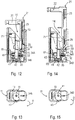
- Fig. 9 to 11 show an intermediate position of the brake disk lock with the rotated cam 41 in the unlocking position, in which the control section 43 due to the first in the direction of rotation D increasing distance of the control section 43 of the rotation axis 42, the second lever arm 34B of the pivot lever 31 in the direction of the adjacent wall of the outer housing thirteenth pivoted.
- the cam 41 may also be rotated by several (e.g., two) revolutions so that unlocking may occur even when the stirrup 21 is temporarily locked and does not jump immediately to its open position.
- FIGS. 14 and 15 show the brake disc lock with the bracket 21 in its open position and the latch 33 in its locked position.
- the brake disc lock can be fixed to a brake disc or the like and then transferred to the closed position.
- a force must be exerted on this, which compresses the temple biasing spring 26 again.
- the bolt 33 slides along the respective gate section 24 and is thereby displaced from the locking position into the unlocked position (similar to FIG Fig. 12 ).
- the bolt 33 in turn slides along the lateral wall of the respective holding portion 29 along until the bracket 21 has reached the closed position. Due to the bias of the pivot lever biasing spring 35 of the latch 33 jumps from the unlocked position in the locked position and passes with the blocking portion 15 of the outer housing 13 and the locking portion 25 of the bracket 21 in engagement.
- the brake disk lock has an automatic function which renders it unnecessary to operate the electric motor 51 to lock the brake disk lock or the closed bracket 21.
- the first lever arm 34A and the second lever arm 34B face each other. Thereby, a certain mass balance between the first lever arm 34A with the latch 33, 34B and the second lever arm 34B is achieved.
- the moment of inertia of the pivoting lever 31, including the bolt 33 is very small compared with the pulses acting on the brake disk lock from outside and against the pivot axis 32.
- an unauthorized opening of the brake disc lock by the so-called hammer blow method in which a moment of inertia of the bolt 33 is to be exploited to temporarily put this in the unlocked position, largely excluded. In principle, it is not necessary to bring about a complete mass balance on the pivot lever 31 for this purpose.
- pivot lever biasing spring 35 Any remaining low moment of inertia with respect to the pivot axis 32, which could lead to a rotational movement of the pivot lever 31 by a translational pulse acting transversely to the pivot axis 32, can be compensated by the pivot lever biasing spring 35.
Landscapes
- Engineering & Computer Science (AREA)
- Mechanical Engineering (AREA)
- Lock And Its Accessories (AREA)
- Braking Arrangements (AREA)
- Magnetically Actuated Valves (AREA)
- Devices For Conveying Motion By Means Of Endless Flexible Members (AREA)
Applications Claiming Priority (1)
| Application Number | Priority Date | Filing Date | Title |
|---|---|---|---|
| DE102018111305.6A DE102018111305A1 (de) | 2018-05-11 | 2018-05-11 | Bügelschloss |
Publications (2)
| Publication Number | Publication Date |
|---|---|
| EP3575520A1 true EP3575520A1 (fr) | 2019-12-04 |
| EP3575520B1 EP3575520B1 (fr) | 2020-12-30 |
Family
ID=66448442
Family Applications (1)
| Application Number | Title | Priority Date | Filing Date |
|---|---|---|---|
| EP19173197.5A Active EP3575520B1 (fr) | 2018-05-11 | 2019-05-08 | Cadenas à arceau |
Country Status (8)
| Country | Link |
|---|---|
| US (1) | US10774567B2 (fr) |
| EP (1) | EP3575520B1 (fr) |
| CN (1) | CN110469212B (fr) |
| AU (1) | AU2019202735A1 (fr) |
| CA (1) | CA3039969A1 (fr) |
| DE (1) | DE102018111305A1 (fr) |
| ES (1) | ES2859736T3 (fr) |
| TW (1) | TWI816780B (fr) |
Families Citing this family (5)
| Publication number | Priority date | Publication date | Assignee | Title |
|---|---|---|---|---|
| US10774566B2 (en) * | 2018-01-23 | 2020-09-15 | Purimee Qianhai (Shenzhen) Intelligent Technology Co., Ltd. | Fingerprint padlock |
| US10858864B2 (en) * | 2018-11-09 | 2020-12-08 | Schlage Lock Company Llc | Motor-driven lock with roller |
| CN111364841B (zh) * | 2020-04-26 | 2023-06-09 | 台州保镖锁业有限公司 | 一种带应急锁安全保护的智能鼓刹锁 |
| DE102021122247A1 (de) | 2021-08-27 | 2023-03-02 | ABUS August Bremicker Söhne Kommanditgesellschaft | Elektromechanisches Schloss |
| DE102022100409A1 (de) | 2022-01-10 | 2023-07-13 | ABUS August Bremicker Söhne Kommanditgesellschaft | Mobiles elektronisches Schloss |
Citations (9)
| Publication number | Priority date | Publication date | Assignee | Title |
|---|---|---|---|---|
| US105710A (en) * | 1870-07-26 | Improvement in padlocks | ||
| US848633A (en) * | 1906-06-09 | 1907-04-02 | Chester Arthur Chubb | Padlock. |
| US957033A (en) * | 1909-07-17 | 1910-05-03 | August M H De Bruycker | Padlock. |
| FR596278A (fr) * | 1925-04-04 | 1925-10-20 | Perfectionnements aux cadenas à anse sautante | |
| US1659664A (en) * | 1924-01-24 | 1928-02-21 | Sargent & Co | Padlock |
| FR644221A (fr) * | 1927-04-23 | 1928-10-04 | Perfectionnements aux cadenas à anse à enclenchement automatique | |
| US1703193A (en) * | 1927-12-07 | 1929-02-26 | Briggs & Stratton Corp | Padlock |
| EP2267256A2 (fr) * | 2009-06-23 | 2010-12-29 | ABUS August Bremicker Söhne KG | Cadenas |
| CN106836989A (zh) * | 2017-01-20 | 2017-06-13 | 浙江浦江梅花锁业集团有限公司 | 一种挂锁 |
Family Cites Families (20)
| Publication number | Priority date | Publication date | Assignee | Title |
|---|---|---|---|---|
| US1246287A (en) * | 1914-03-10 | 1917-11-13 | Om Edwards Co Inc | Padlock. |
| US1564462A (en) * | 1923-12-06 | 1925-12-08 | Frank E Best Inc | Padlock |
| US1743331A (en) * | 1929-02-02 | 1930-01-14 | Ellison Moses | Padlock |
| US2160294A (en) * | 1937-11-17 | 1939-05-30 | Master Lock Co | Padlock |
| US2281088A (en) * | 1940-06-28 | 1942-04-28 | Eagle Lock Company | Rap-proof padlock |
| US2419213A (en) * | 1945-02-14 | 1947-04-22 | Norwalk Lock Company | Padlock |
| US2678554A (en) * | 1952-06-30 | 1954-05-18 | Palmer Luther | Padlock |
| US3901057A (en) * | 1974-05-01 | 1975-08-26 | Sr Clifford L Coley | Padlock |
| US4112716A (en) * | 1976-05-18 | 1978-09-12 | Research Machine & Development, Inc. | Padlock device |
| US5791172A (en) * | 1996-09-20 | 1998-08-11 | Multacc Corporation | Electronically controlled security container for retaining door key |
| DE10026701A1 (de) * | 2000-05-30 | 2001-12-06 | Bremicker Soehne Kg A | Bügelschloß |
| US7076976B1 (en) * | 2005-04-11 | 2006-07-18 | Ilan Goldman | Inertial blocking mechanism |
| US6993943B1 (en) * | 2005-07-26 | 2006-02-07 | Ez Trend Technology Co., Ltd. | Electric Padlock |
| DE102005043927A1 (de) | 2005-09-14 | 2007-03-22 | ABUS August Bremicker Söhne KG | Bremsscheibenschloss |
| US20110023563A1 (en) * | 2009-07-29 | 2011-02-03 | Chien-Yung Huang | Two-way opened padlock |
| US20130086956A1 (en) * | 2011-09-30 | 2013-04-11 | Master Lock Company Llc | Multiple mode locking arrangements |
| DE102013207268A1 (de) * | 2013-04-22 | 2014-10-23 | ABUS August Bremicker Söhne KG | Hangschloss |
| FI126753B (fi) * | 2014-06-27 | 2017-05-15 | Abloy Oy | Riippulukko |
| TWI637099B (zh) * | 2016-10-04 | 2018-10-01 | 萊能科技私人有限公司 | 掛鎖 |
| CN206513156U (zh) * | 2017-03-01 | 2017-09-22 | 三峡大学 | 一种物流电子挂锁 |
-
2018
- 2018-05-11 DE DE102018111305.6A patent/DE102018111305A1/de active Pending
-
2019
- 2019-04-11 CA CA3039969A patent/CA3039969A1/fr active Pending
- 2019-04-18 AU AU2019202735A patent/AU2019202735A1/en active Pending
- 2019-04-25 TW TW108114499A patent/TWI816780B/zh active
- 2019-05-08 EP EP19173197.5A patent/EP3575520B1/fr active Active
- 2019-05-08 ES ES19173197T patent/ES2859736T3/es active Active
- 2019-05-09 US US16/407,563 patent/US10774567B2/en active Active
- 2019-05-10 CN CN201910388477.4A patent/CN110469212B/zh active Active
Patent Citations (10)
| Publication number | Priority date | Publication date | Assignee | Title |
|---|---|---|---|---|
| US105710A (en) * | 1870-07-26 | Improvement in padlocks | ||
| US848633A (en) * | 1906-06-09 | 1907-04-02 | Chester Arthur Chubb | Padlock. |
| US957033A (en) * | 1909-07-17 | 1910-05-03 | August M H De Bruycker | Padlock. |
| US1659664A (en) * | 1924-01-24 | 1928-02-21 | Sargent & Co | Padlock |
| FR596278A (fr) * | 1925-04-04 | 1925-10-20 | Perfectionnements aux cadenas à anse sautante | |
| FR644221A (fr) * | 1927-04-23 | 1928-10-04 | Perfectionnements aux cadenas à anse à enclenchement automatique | |
| US1703193A (en) * | 1927-12-07 | 1929-02-26 | Briggs & Stratton Corp | Padlock |
| EP2267256A2 (fr) * | 2009-06-23 | 2010-12-29 | ABUS August Bremicker Söhne KG | Cadenas |
| DE102009030031A1 (de) | 2009-06-23 | 2010-12-30 | ABUS August Bremicker Söhne KG | Bügelschloss |
| CN106836989A (zh) * | 2017-01-20 | 2017-06-13 | 浙江浦江梅花锁业集团有限公司 | 一种挂锁 |
Also Published As
| Publication number | Publication date |
|---|---|
| CN110469212A (zh) | 2019-11-19 |
| DE102018111305A1 (de) | 2019-11-14 |
| EP3575520B1 (fr) | 2020-12-30 |
| AU2019202735A1 (en) | 2019-11-28 |
| CA3039969A1 (fr) | 2019-11-11 |
| TWI816780B (zh) | 2023-10-01 |
| US10774567B2 (en) | 2020-09-15 |
| TW201947104A (zh) | 2019-12-16 |
| ES2859736T3 (es) | 2021-10-04 |
| US20190344849A1 (en) | 2019-11-14 |
| CN110469212B (zh) | 2022-06-07 |
Similar Documents
| Publication | Publication Date | Title |
|---|---|---|
| EP3575520B1 (fr) | Cadenas à arceau | |
| EP2020474B1 (fr) | Serrure | |
| EP2019178B1 (fr) | Serrure à barres articulées | |
| EP1760230B1 (fr) | Serrure | |
| EP3591147B1 (fr) | Serrure de deux roues ayant une fonction d'alarme | |
| EP2267256B1 (fr) | Cadenas | |
| EP3617428B1 (fr) | Fermeture pour deux-roues | |
| DE102007044088A1 (de) | Binär codierter Schlüssel und manipulationssicheres Schloss | |
| DE102007035218A1 (de) | Elektrisch automatisiert entriegelbares Schloss, insbesondere für schließfachartige Aufbewahrungssysteme | |
| DE102007058550A1 (de) | Bremsscheibenschloss | |
| DE202017101646U1 (de) | Flügelrahmen eines Fensters oder einer Tür | |
| DE102009006495A1 (de) | Schloss, insbesondere Schwenkriegelschloss, mit erhöhter Schutzwirkung | |
| WO2006053597A1 (fr) | Dispositif de fermeture | |
| EP0280755B1 (fr) | Serrure électrique à commande électronique; application aux serrures à mortaise | |
| DE10360225B3 (de) | Elektrisch betätigbarer Türöffner | |
| DE102009053563B4 (de) | Lenkradschlossvorrichtung | |
| EP2075177B1 (fr) | Serrure de frein à disques | |
| EP2060714A2 (fr) | Crémone-serrure | |
| EP2213818B1 (fr) | Serrure, notamment serrure à pêne dormant, de protection améliorée | |
| EP3655601B1 (fr) | Serrure | |
| DE2605763C3 (de) | Treibstangenschloß mit Falle | |
| AT522762A1 (de) | Schloss | |
| EP2738324A2 (fr) | Serrure dotée d'une unité de rotation débloquable | |
| DE4031842C2 (de) | Kraftfahrzeugtürverschluß | |
| EP0136570A2 (fr) | Dispositif pour arrêter des éléments mobiles l'un par rapport à l'autre |
Legal Events
| Date | Code | Title | Description |
|---|---|---|---|
| PUAI | Public reference made under article 153(3) epc to a published international application that has entered the european phase |
Free format text: ORIGINAL CODE: 0009012 |
|
| STAA | Information on the status of an ep patent application or granted ep patent |
Free format text: STATUS: THE APPLICATION HAS BEEN PUBLISHED |
|
| AK | Designated contracting states |
Kind code of ref document: A1 Designated state(s): AL AT BE BG CH CY CZ DE DK EE ES FI FR GB GR HR HU IE IS IT LI LT LU LV MC MK MT NL NO PL PT RO RS SE SI SK SM TR |
|
| AX | Request for extension of the european patent |
Extension state: BA ME |
|
| STAA | Information on the status of an ep patent application or granted ep patent |
Free format text: STATUS: REQUEST FOR EXAMINATION WAS MADE |
|
| 17P | Request for examination filed |
Effective date: 20200330 |
|
| RBV | Designated contracting states (corrected) |
Designated state(s): AL AT BE BG CH CY CZ DE DK EE ES FI FR GB GR HR HU IE IS IT LI LT LU LV MC MK MT NL NO PL PT RO RS SE SI SK SM TR |
|
| GRAP | Despatch of communication of intention to grant a patent |
Free format text: ORIGINAL CODE: EPIDOSNIGR1 |
|
| STAA | Information on the status of an ep patent application or granted ep patent |
Free format text: STATUS: GRANT OF PATENT IS INTENDED |
|
| RIC1 | Information provided on ipc code assigned before grant |
Ipc: E05B 47/00 20060101ALI20200612BHEP Ipc: E05B 67/22 20060101AFI20200612BHEP |
|
| INTG | Intention to grant announced |
Effective date: 20200707 |
|
| GRAS | Grant fee paid |
Free format text: ORIGINAL CODE: EPIDOSNIGR3 |
|
| GRAA | (expected) grant |
Free format text: ORIGINAL CODE: 0009210 |
|
| STAA | Information on the status of an ep patent application or granted ep patent |
Free format text: STATUS: THE PATENT HAS BEEN GRANTED |
|
| AK | Designated contracting states |
Kind code of ref document: B1 Designated state(s): AL AT BE BG CH CY CZ DE DK EE ES FI FR GB GR HR HU IE IS IT LI LT LU LV MC MK MT NL NO PL PT RO RS SE SI SK SM TR |
|
| REG | Reference to a national code |
Ref country code: GB Ref legal event code: FG4D Free format text: NOT ENGLISH |
|
| REG | Reference to a national code |
Ref country code: DE Ref legal event code: R096 Ref document number: 502019000602 Country of ref document: DE |
|
| REG | Reference to a national code |
Ref country code: AT Ref legal event code: REF Ref document number: 1350071 Country of ref document: AT Kind code of ref document: T Effective date: 20210115 Ref country code: CH Ref legal event code: NV Representative=s name: DR. GRAF AND PARTNER AG INTELLECTUAL PROPERTY, CH |
|
| REG | Reference to a national code |
Ref country code: IE Ref legal event code: FG4D Free format text: LANGUAGE OF EP DOCUMENT: GERMAN |
|
| REG | Reference to a national code |
Ref country code: SE Ref legal event code: TRGR |
|
| REG | Reference to a national code |
Ref country code: NL Ref legal event code: FP |
|
| PG25 | Lapsed in a contracting state [announced via postgrant information from national office to epo] |
Ref country code: RS Free format text: LAPSE BECAUSE OF FAILURE TO SUBMIT A TRANSLATION OF THE DESCRIPTION OR TO PAY THE FEE WITHIN THE PRESCRIBED TIME-LIMIT Effective date: 20201230 Ref country code: FI Free format text: LAPSE BECAUSE OF FAILURE TO SUBMIT A TRANSLATION OF THE DESCRIPTION OR TO PAY THE FEE WITHIN THE PRESCRIBED TIME-LIMIT Effective date: 20201230 |
|
| PG25 | Lapsed in a contracting state [announced via postgrant information from national office to epo] |
Ref country code: LV Free format text: LAPSE BECAUSE OF FAILURE TO SUBMIT A TRANSLATION OF THE DESCRIPTION OR TO PAY THE FEE WITHIN THE PRESCRIBED TIME-LIMIT Effective date: 20201230 Ref country code: BG Free format text: LAPSE BECAUSE OF FAILURE TO SUBMIT A TRANSLATION OF THE DESCRIPTION OR TO PAY THE FEE WITHIN THE PRESCRIBED TIME-LIMIT Effective date: 20210330 |
|
| REG | Reference to a national code |
Ref country code: NO Ref legal event code: T2 Effective date: 20201230 |
|
| PG25 | Lapsed in a contracting state [announced via postgrant information from national office to epo] |
Ref country code: HR Free format text: LAPSE BECAUSE OF FAILURE TO SUBMIT A TRANSLATION OF THE DESCRIPTION OR TO PAY THE FEE WITHIN THE PRESCRIBED TIME-LIMIT Effective date: 20201230 |
|
| REG | Reference to a national code |
Ref country code: LT Ref legal event code: MG9D |
|
| PG25 | Lapsed in a contracting state [announced via postgrant information from national office to epo] |
Ref country code: PT Free format text: LAPSE BECAUSE OF FAILURE TO SUBMIT A TRANSLATION OF THE DESCRIPTION OR TO PAY THE FEE WITHIN THE PRESCRIBED TIME-LIMIT Effective date: 20210430 Ref country code: RO Free format text: LAPSE BECAUSE OF FAILURE TO SUBMIT A TRANSLATION OF THE DESCRIPTION OR TO PAY THE FEE WITHIN THE PRESCRIBED TIME-LIMIT Effective date: 20201230 Ref country code: LT Free format text: LAPSE BECAUSE OF FAILURE TO SUBMIT A TRANSLATION OF THE DESCRIPTION OR TO PAY THE FEE WITHIN THE PRESCRIBED TIME-LIMIT Effective date: 20201230 Ref country code: CZ Free format text: LAPSE BECAUSE OF FAILURE TO SUBMIT A TRANSLATION OF THE DESCRIPTION OR TO PAY THE FEE WITHIN THE PRESCRIBED TIME-LIMIT Effective date: 20201230 Ref country code: SK Free format text: LAPSE BECAUSE OF FAILURE TO SUBMIT A TRANSLATION OF THE DESCRIPTION OR TO PAY THE FEE WITHIN THE PRESCRIBED TIME-LIMIT Effective date: 20201230 Ref country code: EE Free format text: LAPSE BECAUSE OF FAILURE TO SUBMIT A TRANSLATION OF THE DESCRIPTION OR TO PAY THE FEE WITHIN THE PRESCRIBED TIME-LIMIT Effective date: 20201230 |
|
| PG25 | Lapsed in a contracting state [announced via postgrant information from national office to epo] |
Ref country code: PL Free format text: LAPSE BECAUSE OF FAILURE TO SUBMIT A TRANSLATION OF THE DESCRIPTION OR TO PAY THE FEE WITHIN THE PRESCRIBED TIME-LIMIT Effective date: 20201230 |
|
| PG25 | Lapsed in a contracting state [announced via postgrant information from national office to epo] |
Ref country code: IS Free format text: LAPSE BECAUSE OF FAILURE TO SUBMIT A TRANSLATION OF THE DESCRIPTION OR TO PAY THE FEE WITHIN THE PRESCRIBED TIME-LIMIT Effective date: 20210430 |
|
| REG | Reference to a national code |
Ref country code: DE Ref legal event code: R097 Ref document number: 502019000602 Country of ref document: DE |
|
| REG | Reference to a national code |
Ref country code: ES Ref legal event code: FG2A Ref document number: 2859736 Country of ref document: ES Kind code of ref document: T3 Effective date: 20211004 |
|
| PG25 | Lapsed in a contracting state [announced via postgrant information from national office to epo] |
Ref country code: AL Free format text: LAPSE BECAUSE OF FAILURE TO SUBMIT A TRANSLATION OF THE DESCRIPTION OR TO PAY THE FEE WITHIN THE PRESCRIBED TIME-LIMIT Effective date: 20201230 |
|
| PLBE | No opposition filed within time limit |
Free format text: ORIGINAL CODE: 0009261 |
|
| STAA | Information on the status of an ep patent application or granted ep patent |
Free format text: STATUS: NO OPPOSITION FILED WITHIN TIME LIMIT |
|
| PG25 | Lapsed in a contracting state [announced via postgrant information from national office to epo] |
Ref country code: DK Free format text: LAPSE BECAUSE OF FAILURE TO SUBMIT A TRANSLATION OF THE DESCRIPTION OR TO PAY THE FEE WITHIN THE PRESCRIBED TIME-LIMIT Effective date: 20201230 |
|
| 26N | No opposition filed |
Effective date: 20211001 |
|
| PG25 | Lapsed in a contracting state [announced via postgrant information from national office to epo] |
Ref country code: LU Free format text: LAPSE BECAUSE OF NON-PAYMENT OF DUE FEES Effective date: 20210508 Ref country code: MC Free format text: LAPSE BECAUSE OF FAILURE TO SUBMIT A TRANSLATION OF THE DESCRIPTION OR TO PAY THE FEE WITHIN THE PRESCRIBED TIME-LIMIT Effective date: 20201230 |
|
| PG25 | Lapsed in a contracting state [announced via postgrant information from national office to epo] |
Ref country code: SI Free format text: LAPSE BECAUSE OF FAILURE TO SUBMIT A TRANSLATION OF THE DESCRIPTION OR TO PAY THE FEE WITHIN THE PRESCRIBED TIME-LIMIT Effective date: 20201230 |
|
| PG25 | Lapsed in a contracting state [announced via postgrant information from national office to epo] |
Ref country code: IE Free format text: LAPSE BECAUSE OF NON-PAYMENT OF DUE FEES Effective date: 20210508 |
|
| PG25 | Lapsed in a contracting state [announced via postgrant information from national office to epo] |
Ref country code: IS Free format text: LAPSE BECAUSE OF FAILURE TO SUBMIT A TRANSLATION OF THE DESCRIPTION OR TO PAY THE FEE WITHIN THE PRESCRIBED TIME-LIMIT Effective date: 20210430 |
|
| PG25 | Lapsed in a contracting state [announced via postgrant information from national office to epo] |
Ref country code: CY Free format text: LAPSE BECAUSE OF FAILURE TO SUBMIT A TRANSLATION OF THE DESCRIPTION OR TO PAY THE FEE WITHIN THE PRESCRIBED TIME-LIMIT Effective date: 20201230 |
|
| PG25 | Lapsed in a contracting state [announced via postgrant information from national office to epo] |
Ref country code: SM Free format text: LAPSE BECAUSE OF FAILURE TO SUBMIT A TRANSLATION OF THE DESCRIPTION OR TO PAY THE FEE WITHIN THE PRESCRIBED TIME-LIMIT Effective date: 20201230 Ref country code: HU Free format text: LAPSE BECAUSE OF FAILURE TO SUBMIT A TRANSLATION OF THE DESCRIPTION OR TO PAY THE FEE WITHIN THE PRESCRIBED TIME-LIMIT; INVALID AB INITIO Effective date: 20190508 Ref country code: GR Free format text: LAPSE BECAUSE OF FAILURE TO SUBMIT A TRANSLATION OF THE DESCRIPTION OR TO PAY THE FEE WITHIN THE PRESCRIBED TIME-LIMIT Effective date: 20201230 |
|
| PGFP | Annual fee paid to national office [announced via postgrant information from national office to epo] |
Ref country code: IT Payment date: 20230526 Year of fee payment: 5 |
|
| PGFP | Annual fee paid to national office [announced via postgrant information from national office to epo] |
Ref country code: DE Payment date: 20230727 Year of fee payment: 5 |
|
| PG25 | Lapsed in a contracting state [announced via postgrant information from national office to epo] |
Ref country code: MK Free format text: LAPSE BECAUSE OF FAILURE TO SUBMIT A TRANSLATION OF THE DESCRIPTION OR TO PAY THE FEE WITHIN THE PRESCRIBED TIME-LIMIT Effective date: 20201230 |
|
| PGFP | Annual fee paid to national office [announced via postgrant information from national office to epo] |
Ref country code: NL Payment date: 20240521 Year of fee payment: 6 |
|
| PGFP | Annual fee paid to national office [announced via postgrant information from national office to epo] |
Ref country code: GB Payment date: 20240521 Year of fee payment: 6 |
|
| PGFP | Annual fee paid to national office [announced via postgrant information from national office to epo] |
Ref country code: CH Payment date: 20240602 Year of fee payment: 6 |
|
| PGFP | Annual fee paid to national office [announced via postgrant information from national office to epo] |
Ref country code: ES Payment date: 20240627 Year of fee payment: 6 |
|
| PGFP | Annual fee paid to national office [announced via postgrant information from national office to epo] |
Ref country code: AT Payment date: 20240522 Year of fee payment: 6 |
|
| PGFP | Annual fee paid to national office [announced via postgrant information from national office to epo] |
Ref country code: NO Payment date: 20240528 Year of fee payment: 6 Ref country code: FR Payment date: 20240528 Year of fee payment: 6 |
|
| PGFP | Annual fee paid to national office [announced via postgrant information from national office to epo] |
Ref country code: SE Payment date: 20240521 Year of fee payment: 6 Ref country code: BE Payment date: 20240521 Year of fee payment: 6 |