EP3780184A1 - Matériau d'électrode négative servant à un accumulateur au lithium-ion, procédé de production de matériau d'électrode négative servant à un accumulateur au lithium-ion, électrode négative destinée à un accumulateur au lithium-ion au lithium-ion et accumulateur au lithium-ion - Google Patents
Matériau d'électrode négative servant à un accumulateur au lithium-ion, procédé de production de matériau d'électrode négative servant à un accumulateur au lithium-ion, électrode négative destinée à un accumulateur au lithium-ion au lithium-ion et accumulateur au lithium-ion Download PDFInfo
- Publication number
- EP3780184A1 EP3780184A1 EP18912877.0A EP18912877A EP3780184A1 EP 3780184 A1 EP3780184 A1 EP 3780184A1 EP 18912877 A EP18912877 A EP 18912877A EP 3780184 A1 EP3780184 A1 EP 3780184A1
- Authority
- EP
- European Patent Office
- Prior art keywords
- particles
- negative electrode
- secondary battery
- electrode material
- lithium ion
- Prior art date
- Legal status (The legal status is an assumption and is not a legal conclusion. Google has not performed a legal analysis and makes no representation as to the accuracy of the status listed.)
- Granted
Links
- 239000007773 negative electrode material Substances 0.000 title claims abstract description 171
- HBBGRARXTFLTSG-UHFFFAOYSA-N Lithium ion Chemical compound [Li+] HBBGRARXTFLTSG-UHFFFAOYSA-N 0.000 title claims abstract description 127
- 229910001416 lithium ion Inorganic materials 0.000 title claims abstract description 127
- 239000002002 slurry Substances 0.000 title claims abstract description 16
- 238000004519 manufacturing process Methods 0.000 title claims description 9
- 239000002245 particle Substances 0.000 claims abstract description 609
- OKTJSMMVPCPJKN-UHFFFAOYSA-N Carbon Chemical compound [C] OKTJSMMVPCPJKN-UHFFFAOYSA-N 0.000 claims abstract description 270
- 229910002804 graphite Inorganic materials 0.000 claims abstract description 226
- 239000010439 graphite Substances 0.000 claims abstract description 226
- 238000000034 method Methods 0.000 claims abstract description 67
- 239000000203 mixture Substances 0.000 claims abstract description 61
- XUIMIQQOPSSXEZ-UHFFFAOYSA-N Silicon Chemical group [Si] XUIMIQQOPSSXEZ-UHFFFAOYSA-N 0.000 claims abstract description 29
- 238000002156 mixing Methods 0.000 claims description 32
- 238000010521 absorption reaction Methods 0.000 claims description 31
- 230000008569 process Effects 0.000 claims description 30
- 239000003921 oil Substances 0.000 claims description 29
- IJGRMHOSHXDMSA-UHFFFAOYSA-N Atomic nitrogen Chemical compound N#N IJGRMHOSHXDMSA-UHFFFAOYSA-N 0.000 claims description 18
- 239000011230 binding agent Substances 0.000 claims description 18
- 239000003792 electrolyte Substances 0.000 claims description 13
- 239000002904 solvent Substances 0.000 claims description 9
- 229910001873 dinitrogen Inorganic materials 0.000 claims description 5
- 238000001179 sorption measurement Methods 0.000 claims description 5
- VYPSYNLAJGMNEJ-UHFFFAOYSA-N Silicium dioxide Chemical compound O=[Si]=O VYPSYNLAJGMNEJ-UHFFFAOYSA-N 0.000 description 76
- 229910052814 silicon oxide Inorganic materials 0.000 description 75
- 229910052799 carbon Inorganic materials 0.000 description 36
- 238000002360 preparation method Methods 0.000 description 35
- 235000019198 oils Nutrition 0.000 description 28
- 238000003825 pressing Methods 0.000 description 25
- 238000007669 thermal treatment Methods 0.000 description 23
- 238000005087 graphitization Methods 0.000 description 22
- 230000000052 comparative effect Effects 0.000 description 21
- 150000002894 organic compounds Chemical class 0.000 description 21
- 229910021382 natural graphite Inorganic materials 0.000 description 20
- 239000000126 substance Substances 0.000 description 18
- 238000005259 measurement Methods 0.000 description 17
- 239000010703 silicon Substances 0.000 description 17
- 229910052710 silicon Inorganic materials 0.000 description 17
- 238000011156 evaluation Methods 0.000 description 15
- 239000003054 catalyst Substances 0.000 description 14
- 239000011246 composite particle Substances 0.000 description 13
- 239000011271 tar pitch Substances 0.000 description 13
- 238000012360 testing method Methods 0.000 description 13
- 238000009826 distribution Methods 0.000 description 10
- 238000000465 moulding Methods 0.000 description 10
- -1 silicon oxide Chemical class 0.000 description 10
- 239000003575 carbonaceous material Substances 0.000 description 9
- 230000000694 effects Effects 0.000 description 8
- 239000000843 powder Substances 0.000 description 8
- 229910052782 aluminium Inorganic materials 0.000 description 7
- XAGFODPZIPBFFR-UHFFFAOYSA-N aluminium Chemical compound [Al] XAGFODPZIPBFFR-UHFFFAOYSA-N 0.000 description 7
- 229910021383 artificial graphite Inorganic materials 0.000 description 7
- 238000001035 drying Methods 0.000 description 7
- 229910052751 metal Inorganic materials 0.000 description 7
- 239000002184 metal Substances 0.000 description 7
- 239000004570 mortar (masonry) Substances 0.000 description 7
- 239000012299 nitrogen atmosphere Substances 0.000 description 7
- 239000000463 material Substances 0.000 description 6
- 229910052757 nitrogen Inorganic materials 0.000 description 6
- XLYOFNOQVPJJNP-UHFFFAOYSA-N water Substances O XLYOFNOQVPJJNP-UHFFFAOYSA-N 0.000 description 6
- PXHVJJICTQNCMI-UHFFFAOYSA-N Nickel Chemical compound [Ni] PXHVJJICTQNCMI-UHFFFAOYSA-N 0.000 description 5
- 238000002441 X-ray diffraction Methods 0.000 description 5
- 239000012298 atmosphere Substances 0.000 description 5
- 239000000571 coke Substances 0.000 description 5
- 239000013078 crystal Substances 0.000 description 5
- 230000002349 favourable effect Effects 0.000 description 5
- 238000004898 kneading Methods 0.000 description 5
- 238000012423 maintenance Methods 0.000 description 5
- 230000003647 oxidation Effects 0.000 description 5
- 238000007254 oxidation reaction Methods 0.000 description 5
- HBMJWWWQQXIZIP-UHFFFAOYSA-N silicon carbide Chemical compound [Si+]#[C-] HBMJWWWQQXIZIP-UHFFFAOYSA-N 0.000 description 5
- 229910010271 silicon carbide Inorganic materials 0.000 description 5
- YEJRWHAVMIAJKC-UHFFFAOYSA-N 4-Butyrolactone Chemical compound O=C1CCCO1 YEJRWHAVMIAJKC-UHFFFAOYSA-N 0.000 description 4
- NIXOWILDQLNWCW-UHFFFAOYSA-M Acrylate Chemical compound [O-]C(=O)C=C NIXOWILDQLNWCW-UHFFFAOYSA-M 0.000 description 4
- XKRFYHLGVUSROY-UHFFFAOYSA-N Argon Chemical compound [Ar] XKRFYHLGVUSROY-UHFFFAOYSA-N 0.000 description 4
- 229920002134 Carboxymethyl cellulose Polymers 0.000 description 4
- RYGMFSIKBFXOCR-UHFFFAOYSA-N Copper Chemical compound [Cu] RYGMFSIKBFXOCR-UHFFFAOYSA-N 0.000 description 4
- UFWIBTONFRDIAS-UHFFFAOYSA-N Naphthalene Chemical compound C1=CC=CC2=CC=CC=C21 UFWIBTONFRDIAS-UHFFFAOYSA-N 0.000 description 4
- 238000009825 accumulation Methods 0.000 description 4
- MWPLVEDNUUSJAV-UHFFFAOYSA-N anthracene Chemical compound C1=CC=CC2=CC3=CC=CC=C3C=C21 MWPLVEDNUUSJAV-UHFFFAOYSA-N 0.000 description 4
- 239000006229 carbon black Substances 0.000 description 4
- 238000013329 compounding Methods 0.000 description 4
- 238000000280 densification Methods 0.000 description 4
- 238000011161 development Methods 0.000 description 4
- DOIRQSBPFJWKBE-UHFFFAOYSA-N dibutyl phthalate Chemical compound CCCCOC(=O)C1=CC=CC=C1C(=O)OCCCC DOIRQSBPFJWKBE-UHFFFAOYSA-N 0.000 description 4
- 239000006185 dispersion Substances 0.000 description 4
- 238000001125 extrusion Methods 0.000 description 4
- 239000011888 foil Substances 0.000 description 4
- 239000011295 pitch Substances 0.000 description 4
- 238000010298 pulverizing process Methods 0.000 description 4
- 229920005989 resin Polymers 0.000 description 4
- 239000011347 resin Substances 0.000 description 4
- 229920003048 styrene butadiene rubber Polymers 0.000 description 4
- 239000011269 tar Substances 0.000 description 4
- 239000002562 thickening agent Substances 0.000 description 4
- VAYTZRYEBVHVLE-UHFFFAOYSA-N 1,3-dioxol-2-one Chemical compound O=C1OC=CO1 VAYTZRYEBVHVLE-UHFFFAOYSA-N 0.000 description 3
- XEKOWRVHYACXOJ-UHFFFAOYSA-N Ethyl acetate Chemical compound CCOC(C)=O XEKOWRVHYACXOJ-UHFFFAOYSA-N 0.000 description 3
- XEEYBQQBJWHFJM-UHFFFAOYSA-N Iron Chemical compound [Fe] XEEYBQQBJWHFJM-UHFFFAOYSA-N 0.000 description 3
- ZMXDDKWLCZADIW-UHFFFAOYSA-N N,N-Dimethylformamide Chemical compound CN(C)C=O ZMXDDKWLCZADIW-UHFFFAOYSA-N 0.000 description 3
- 239000004372 Polyvinyl alcohol Substances 0.000 description 3
- 238000001237 Raman spectrum Methods 0.000 description 3
- RTAQQCXQSZGOHL-UHFFFAOYSA-N Titanium Chemical compound [Ti] RTAQQCXQSZGOHL-UHFFFAOYSA-N 0.000 description 3
- 239000006230 acetylene black Substances 0.000 description 3
- 229910045601 alloy Inorganic materials 0.000 description 3
- 239000000956 alloy Substances 0.000 description 3
- 229910003481 amorphous carbon Inorganic materials 0.000 description 3
- 239000001768 carboxy methyl cellulose Substances 0.000 description 3
- 235000010948 carboxy methyl cellulose Nutrition 0.000 description 3
- 239000008112 carboxymethyl-cellulose Substances 0.000 description 3
- 229940105329 carboxymethylcellulose Drugs 0.000 description 3
- 239000003795 chemical substances by application Substances 0.000 description 3
- 230000006872 improvement Effects 0.000 description 3
- 235000021388 linseed oil Nutrition 0.000 description 3
- 239000000944 linseed oil Substances 0.000 description 3
- 239000011259 mixed solution Substances 0.000 description 3
- 229910052759 nickel Inorganic materials 0.000 description 3
- 150000004767 nitrides Chemical class 0.000 description 3
- 229920000642 polymer Polymers 0.000 description 3
- 229920002451 polyvinyl alcohol Polymers 0.000 description 3
- 239000007787 solid Substances 0.000 description 3
- 239000012798 spherical particle Substances 0.000 description 3
- 239000010936 titanium Substances 0.000 description 3
- 239000013585 weight reducing agent Substances 0.000 description 3
- HDTRYLNUVZCQOY-UHFFFAOYSA-N α-D-glucopyranosyl-α-D-glucopyranoside Natural products OC1C(O)C(O)C(CO)OC1OC1C(O)C(O)C(O)C(CO)O1 HDTRYLNUVZCQOY-UHFFFAOYSA-N 0.000 description 2
- SBLRHMKNNHXPHG-UHFFFAOYSA-N 4-fluoro-1,3-dioxolan-2-one Chemical compound FC1COC(=O)O1 SBLRHMKNNHXPHG-UHFFFAOYSA-N 0.000 description 2
- XTHFKEDIFFGKHM-UHFFFAOYSA-N Dimethoxyethane Chemical compound COCCOC XTHFKEDIFFGKHM-UHFFFAOYSA-N 0.000 description 2
- KMTRUDSVKNLOMY-UHFFFAOYSA-N Ethylene carbonate Chemical compound O=C1OCCO1 KMTRUDSVKNLOMY-UHFFFAOYSA-N 0.000 description 2
- 229910001200 Ferrotitanium Inorganic materials 0.000 description 2
- VZCYOOQTPOCHFL-OWOJBTEDSA-N Fumaric acid Chemical compound OC(=O)\C=C\C(O)=O VZCYOOQTPOCHFL-OWOJBTEDSA-N 0.000 description 2
- 229910011396 LiCoxNiyMnzO2 Inorganic materials 0.000 description 2
- 229910014623 LiNi2-xMnxO4 Inorganic materials 0.000 description 2
- 229910001290 LiPF6 Inorganic materials 0.000 description 2
- 239000004698 Polyethylene Substances 0.000 description 2
- 239000004373 Pullulan Substances 0.000 description 2
- 229920001218 Pullulan Polymers 0.000 description 2
- WYURNTSHIVDZCO-UHFFFAOYSA-N Tetrahydrofuran Chemical compound C1CCOC1 WYURNTSHIVDZCO-UHFFFAOYSA-N 0.000 description 2
- GWEVSGVZZGPLCZ-UHFFFAOYSA-N Titan oxide Chemical compound O=[Ti]=O GWEVSGVZZGPLCZ-UHFFFAOYSA-N 0.000 description 2
- HDTRYLNUVZCQOY-WSWWMNSNSA-N Trehalose Natural products O[C@@H]1[C@@H](O)[C@@H](O)[C@@H](CO)O[C@@H]1O[C@@H]1[C@H](O)[C@@H](O)[C@@H](O)[C@@H](CO)O1 HDTRYLNUVZCQOY-WSWWMNSNSA-N 0.000 description 2
- DGEZNRSVGBDHLK-UHFFFAOYSA-N [1,10]phenanthroline Chemical compound C1=CN=C2C3=NC=CC=C3C=CC2=C1 DGEZNRSVGBDHLK-UHFFFAOYSA-N 0.000 description 2
- HDTRYLNUVZCQOY-LIZSDCNHSA-N alpha,alpha-trehalose Chemical compound O[C@@H]1[C@@H](O)[C@H](O)[C@@H](CO)O[C@@H]1O[C@@H]1[C@H](O)[C@@H](O)[C@H](O)[C@@H](CO)O1 HDTRYLNUVZCQOY-LIZSDCNHSA-N 0.000 description 2
- 229910052786 argon Inorganic materials 0.000 description 2
- 229910052796 boron Inorganic materials 0.000 description 2
- 239000007833 carbon precursor Substances 0.000 description 2
- 230000008859 change Effects 0.000 description 2
- 238000006243 chemical reaction Methods 0.000 description 2
- 239000003153 chemical reaction reagent Substances 0.000 description 2
- 239000011280 coal tar Substances 0.000 description 2
- 229910052802 copper Inorganic materials 0.000 description 2
- 239000010949 copper Substances 0.000 description 2
- 239000011889 copper foil Substances 0.000 description 2
- BGTOWKSIORTVQH-UHFFFAOYSA-N cyclopentanone Chemical compound O=C1CCCC1 BGTOWKSIORTVQH-UHFFFAOYSA-N 0.000 description 2
- 239000003822 epoxy resin Substances 0.000 description 2
- JBTWLSYIZRCDFO-UHFFFAOYSA-N ethyl methyl carbonate Chemical compound CCOC(=O)OC JBTWLSYIZRCDFO-UHFFFAOYSA-N 0.000 description 2
- 230000009969 flowable effect Effects 0.000 description 2
- 239000012634 fragment Substances 0.000 description 2
- 239000007789 gas Substances 0.000 description 2
- 239000012535 impurity Substances 0.000 description 2
- 239000011261 inert gas Substances 0.000 description 2
- 229910052742 iron Inorganic materials 0.000 description 2
- 239000007788 liquid Substances 0.000 description 2
- 229910000625 lithium cobalt oxide Inorganic materials 0.000 description 2
- 229910002102 lithium manganese oxide Inorganic materials 0.000 description 2
- BFZPBUKRYWOWDV-UHFFFAOYSA-N lithium;oxido(oxo)cobalt Chemical compound [Li+].[O-][Co]=O BFZPBUKRYWOWDV-UHFFFAOYSA-N 0.000 description 2
- VROAXDSNYPAOBJ-UHFFFAOYSA-N lithium;oxido(oxo)nickel Chemical compound [Li+].[O-][Ni]=O VROAXDSNYPAOBJ-UHFFFAOYSA-N 0.000 description 2
- VLXXBCXTUVRROQ-UHFFFAOYSA-N lithium;oxido-oxo-(oxomanganiooxy)manganese Chemical compound [Li+].[O-][Mn](=O)O[Mn]=O VLXXBCXTUVRROQ-UHFFFAOYSA-N 0.000 description 2
- NUJOXMJBOLGQSY-UHFFFAOYSA-N manganese dioxide Chemical compound O=[Mn]=O NUJOXMJBOLGQSY-UHFFFAOYSA-N 0.000 description 2
- 239000011301 petroleum pitch Substances 0.000 description 2
- 239000005011 phenolic resin Substances 0.000 description 2
- 229920000647 polyepoxide Polymers 0.000 description 2
- 229920000573 polyethylene Polymers 0.000 description 2
- 239000011148 porous material Substances 0.000 description 2
- 239000007774 positive electrode material Substances 0.000 description 2
- 235000019423 pullulan Nutrition 0.000 description 2
- 230000005855 radiation Effects 0.000 description 2
- 150000003377 silicon compounds Chemical class 0.000 description 2
- LIVNPJMFVYWSIS-UHFFFAOYSA-N silicon monoxide Chemical class [Si-]#[O+] LIVNPJMFVYWSIS-UHFFFAOYSA-N 0.000 description 2
- 238000000992 sputter etching Methods 0.000 description 2
- 239000010935 stainless steel Substances 0.000 description 2
- 229910001220 stainless steel Inorganic materials 0.000 description 2
- 238000000859 sublimation Methods 0.000 description 2
- 230000008022 sublimation Effects 0.000 description 2
- 229920001187 thermosetting polymer Polymers 0.000 description 2
- VZCYOOQTPOCHFL-UHFFFAOYSA-N trans-butenedioic acid Natural products OC(=O)C=CC(O)=O VZCYOOQTPOCHFL-UHFFFAOYSA-N 0.000 description 2
- ZZXUZKXVROWEIF-UHFFFAOYSA-N 1,2-butylene carbonate Chemical compound CCC1COC(=O)O1 ZZXUZKXVROWEIF-UHFFFAOYSA-N 0.000 description 1
- WNXJIVFYUVYPPR-UHFFFAOYSA-N 1,3-dioxolane Chemical compound C1COCO1 WNXJIVFYUVYPPR-UHFFFAOYSA-N 0.000 description 1
- WKFQMDFSDQFAIC-UHFFFAOYSA-N 2,4-dimethylthiolane 1,1-dioxide Chemical compound CC1CC(C)S(=O)(=O)C1 WKFQMDFSDQFAIC-UHFFFAOYSA-N 0.000 description 1
- SMZOUWXMTYCWNB-UHFFFAOYSA-N 2-(2-methoxy-5-methylphenyl)ethanamine Chemical compound COC1=CC=C(C)C=C1CCN SMZOUWXMTYCWNB-UHFFFAOYSA-N 0.000 description 1
- JAHNSTQSQJOJLO-UHFFFAOYSA-N 2-(3-fluorophenyl)-1h-imidazole Chemical compound FC1=CC=CC(C=2NC=CN=2)=C1 JAHNSTQSQJOJLO-UHFFFAOYSA-N 0.000 description 1
- NIXOWILDQLNWCW-UHFFFAOYSA-N 2-Propenoic acid Natural products OC(=O)C=C NIXOWILDQLNWCW-UHFFFAOYSA-N 0.000 description 1
- JWUJQDFVADABEY-UHFFFAOYSA-N 2-methyltetrahydrofuran Chemical compound CC1CCCO1 JWUJQDFVADABEY-UHFFFAOYSA-N 0.000 description 1
- VWIIJDNADIEEDB-UHFFFAOYSA-N 3-methyl-1,3-oxazolidin-2-one Chemical compound CN1CCOC1=O VWIIJDNADIEEDB-UHFFFAOYSA-N 0.000 description 1
- CMJLMPKFQPJDKP-UHFFFAOYSA-N 3-methylthiolane 1,1-dioxide Chemical compound CC1CCS(=O)(=O)C1 CMJLMPKFQPJDKP-UHFFFAOYSA-N 0.000 description 1
- 229920003026 Acene Polymers 0.000 description 1
- 238000004438 BET method Methods 0.000 description 1
- ZOXJGFHDIHLPTG-UHFFFAOYSA-N Boron Chemical compound [B] ZOXJGFHDIHLPTG-UHFFFAOYSA-N 0.000 description 1
- GAWIXWVDTYZWAW-UHFFFAOYSA-N C[CH]O Chemical group C[CH]O GAWIXWVDTYZWAW-UHFFFAOYSA-N 0.000 description 1
- OIFBSDVPJOWBCH-UHFFFAOYSA-N Diethyl carbonate Chemical compound CCOC(=O)OCC OIFBSDVPJOWBCH-UHFFFAOYSA-N 0.000 description 1
- 239000001856 Ethyl cellulose Substances 0.000 description 1
- ZZSNKZQZMQGXPY-UHFFFAOYSA-N Ethyl cellulose Chemical compound CCOCC1OC(OC)C(OCC)C(OCC)C1OC1C(O)C(O)C(OC)C(CO)O1 ZZSNKZQZMQGXPY-UHFFFAOYSA-N 0.000 description 1
- 238000004566 IR spectroscopy Methods 0.000 description 1
- 229910001305 LiMPO4 Inorganic materials 0.000 description 1
- WHXSMMKQMYFTQS-UHFFFAOYSA-N Lithium Chemical compound [Li] WHXSMMKQMYFTQS-UHFFFAOYSA-N 0.000 description 1
- CERQOIWHTDAKMF-UHFFFAOYSA-N Methacrylic acid Chemical compound CC(=C)C(O)=O CERQOIWHTDAKMF-UHFFFAOYSA-N 0.000 description 1
- 229910016003 MoS3 Inorganic materials 0.000 description 1
- 229910016040 MoV2O8 Inorganic materials 0.000 description 1
- FXHOOIRPVKKKFG-UHFFFAOYSA-N N,N-Dimethylacetamide Chemical compound CN(C)C(C)=O FXHOOIRPVKKKFG-UHFFFAOYSA-N 0.000 description 1
- SECXISVLQFMRJM-UHFFFAOYSA-N N-Methylpyrrolidone Chemical compound CN1CCCC1=O SECXISVLQFMRJM-UHFFFAOYSA-N 0.000 description 1
- 241000282320 Panthera leo Species 0.000 description 1
- 229920003171 Poly (ethylene oxide) Polymers 0.000 description 1
- 239000004962 Polyamide-imide Substances 0.000 description 1
- 239000004642 Polyimide Substances 0.000 description 1
- 239000004743 Polypropylene Substances 0.000 description 1
- OFOBLEOULBTSOW-UHFFFAOYSA-N Propanedioic acid Natural products OC(=O)CC(O)=O OFOBLEOULBTSOW-UHFFFAOYSA-N 0.000 description 1
- XBDQKXXYIPTUBI-UHFFFAOYSA-M Propionate Chemical compound CCC([O-])=O XBDQKXXYIPTUBI-UHFFFAOYSA-M 0.000 description 1
- 238000001069 Raman spectroscopy Methods 0.000 description 1
- 229920002125 Sokalan® Polymers 0.000 description 1
- 229920002472 Starch Polymers 0.000 description 1
- 239000002174 Styrene-butadiene Substances 0.000 description 1
- UCKMPCXJQFINFW-UHFFFAOYSA-N Sulphide Chemical compound [S-2] UCKMPCXJQFINFW-UHFFFAOYSA-N 0.000 description 1
- 229910003092 TiS2 Inorganic materials 0.000 description 1
- ATJFFYVFTNAWJD-UHFFFAOYSA-N Tin Chemical compound [Sn] ATJFFYVFTNAWJD-UHFFFAOYSA-N 0.000 description 1
- OMOVVBIIQSXZSZ-UHFFFAOYSA-N [6-(4-acetyloxy-5,9a-dimethyl-2,7-dioxo-4,5a,6,9-tetrahydro-3h-pyrano[3,4-b]oxepin-5-yl)-5-formyloxy-3-(furan-3-yl)-3a-methyl-7-methylidene-1a,2,3,4,5,6-hexahydroindeno[1,7a-b]oxiren-4-yl] 2-hydroxy-3-methylpentanoate Chemical compound CC12C(OC(=O)C(O)C(C)CC)C(OC=O)C(C3(C)C(CC(=O)OC4(C)COC(=O)CC43)OC(C)=O)C(=C)C32OC3CC1C=1C=COC=1 OMOVVBIIQSXZSZ-UHFFFAOYSA-N 0.000 description 1
- KLARSDUHONHPRF-UHFFFAOYSA-N [Li].[Mn] Chemical compound [Li].[Mn] KLARSDUHONHPRF-UHFFFAOYSA-N 0.000 description 1
- KXKVLQRXCPHEJC-UHFFFAOYSA-N acetic acid trimethyl ester Natural products COC(C)=O KXKVLQRXCPHEJC-UHFFFAOYSA-N 0.000 description 1
- 229920006243 acrylic copolymer Polymers 0.000 description 1
- 238000004458 analytical method Methods 0.000 description 1
- 230000003466 anti-cipated effect Effects 0.000 description 1
- 239000007864 aqueous solution Substances 0.000 description 1
- 239000003125 aqueous solvent Substances 0.000 description 1
- 239000011324 bead Substances 0.000 description 1
- 230000015572 biosynthetic process Effects 0.000 description 1
- MTAZNLWOLGHBHU-UHFFFAOYSA-N butadiene-styrene rubber Chemical compound C=CC=C.C=CC1=CC=CC=C1 MTAZNLWOLGHBHU-UHFFFAOYSA-N 0.000 description 1
- CTZGGNZWFSDEGK-UHFFFAOYSA-N butyl ethyl carbonate Chemical compound [CH2]COC(=O)OCCCC CTZGGNZWFSDEGK-UHFFFAOYSA-N 0.000 description 1
- 125000000484 butyl group Chemical group [H]C([*])([H])C([H])([H])C([H])([H])C([H])([H])[H] 0.000 description 1
- FWBMVXOCTXTBAD-UHFFFAOYSA-N butyl methyl carbonate Chemical compound CCCCOC(=O)OC FWBMVXOCTXTBAD-UHFFFAOYSA-N 0.000 description 1
- 150000001732 carboxylic acid derivatives Chemical class 0.000 description 1
- 150000001733 carboxylic acid esters Chemical class 0.000 description 1
- 239000005018 casein Substances 0.000 description 1
- BECPQYXYKAMYBN-UHFFFAOYSA-N casein, tech. Chemical compound NCCCCC(C(O)=O)N=C(O)C(CC(O)=O)N=C(O)C(CCC(O)=N)N=C(O)C(CC(C)C)N=C(O)C(CCC(O)=O)N=C(O)C(CC(O)=O)N=C(O)C(CCC(O)=O)N=C(O)C(C(C)O)N=C(O)C(CCC(O)=N)N=C(O)C(CCC(O)=N)N=C(O)C(CCC(O)=N)N=C(O)C(CCC(O)=O)N=C(O)C(CCC(O)=O)N=C(O)C(COP(O)(O)=O)N=C(O)C(CCC(O)=N)N=C(O)C(N)CC1=CC=CC=C1 BECPQYXYKAMYBN-UHFFFAOYSA-N 0.000 description 1
- 235000021240 caseins Nutrition 0.000 description 1
- 230000015556 catabolic process Effects 0.000 description 1
- 230000003197 catalytic effect Effects 0.000 description 1
- 239000002734 clay mineral Substances 0.000 description 1
- 239000011248 coating agent Substances 0.000 description 1
- 238000000576 coating method Methods 0.000 description 1
- 229910052681 coesite Inorganic materials 0.000 description 1
- 150000001875 compounds Chemical class 0.000 description 1
- 230000006835 compression Effects 0.000 description 1
- 238000007906 compression Methods 0.000 description 1
- 239000000470 constituent Substances 0.000 description 1
- 229910052906 cristobalite Inorganic materials 0.000 description 1
- 230000003247 decreasing effect Effects 0.000 description 1
- IEJIGPNLZYLLBP-UHFFFAOYSA-N dimethyl carbonate Chemical compound COC(=O)OC IEJIGPNLZYLLBP-UHFFFAOYSA-N 0.000 description 1
- 238000003618 dip coating Methods 0.000 description 1
- VUPKGFBOKBGHFZ-UHFFFAOYSA-N dipropyl carbonate Chemical compound CCCOC(=O)OCCC VUPKGFBOKBGHFZ-UHFFFAOYSA-N 0.000 description 1
- 238000007323 disproportionation reaction Methods 0.000 description 1
- 238000007606 doctor blade method Methods 0.000 description 1
- 229920001971 elastomer Polymers 0.000 description 1
- 239000007772 electrode material Substances 0.000 description 1
- 238000009503 electrostatic coating Methods 0.000 description 1
- 230000007613 environmental effect Effects 0.000 description 1
- 229920001249 ethyl cellulose Polymers 0.000 description 1
- 235000019325 ethyl cellulose Nutrition 0.000 description 1
- 229960004667 ethyl cellulose Drugs 0.000 description 1
- 125000001495 ethyl group Chemical group [H]C([H])([H])C([H])([H])* 0.000 description 1
- QKBJDEGZZJWPJA-UHFFFAOYSA-N ethyl propyl carbonate Chemical compound [CH2]COC(=O)OCCC QKBJDEGZZJWPJA-UHFFFAOYSA-N 0.000 description 1
- 230000005284 excitation Effects 0.000 description 1
- 239000004744 fabric Substances 0.000 description 1
- 239000012530 fluid Substances 0.000 description 1
- 239000001530 fumaric acid Substances 0.000 description 1
- 238000007756 gravure coating Methods 0.000 description 1
- 239000001307 helium Substances 0.000 description 1
- 229910052734 helium Inorganic materials 0.000 description 1
- SWQJXJOGLNCZEY-UHFFFAOYSA-N helium atom Chemical compound [He] SWQJXJOGLNCZEY-UHFFFAOYSA-N 0.000 description 1
- 229920003063 hydroxymethyl cellulose Polymers 0.000 description 1
- 229940031574 hydroxymethyl cellulose Drugs 0.000 description 1
- 230000010354 integration Effects 0.000 description 1
- 229910000765 intermetallic Inorganic materials 0.000 description 1
- 229910052744 lithium Inorganic materials 0.000 description 1
- 229910001540 lithium hexafluoroarsenate(V) Inorganic materials 0.000 description 1
- MHCFAGZWMAWTNR-UHFFFAOYSA-M lithium perchlorate Chemical compound [Li+].[O-]Cl(=O)(=O)=O MHCFAGZWMAWTNR-UHFFFAOYSA-M 0.000 description 1
- 229910001486 lithium perchlorate Inorganic materials 0.000 description 1
- 229910003002 lithium salt Inorganic materials 0.000 description 1
- 159000000002 lithium salts Chemical class 0.000 description 1
- 229910001496 lithium tetrafluoroborate Inorganic materials 0.000 description 1
- DMEJJWCBIYKVSB-UHFFFAOYSA-N lithium vanadium Chemical compound [Li].[V] DMEJJWCBIYKVSB-UHFFFAOYSA-N 0.000 description 1
- MCVFFRWZNYZUIJ-UHFFFAOYSA-M lithium;trifluoromethanesulfonate Chemical compound [Li+].[O-]S(=O)(=O)C(F)(F)F MCVFFRWZNYZUIJ-UHFFFAOYSA-M 0.000 description 1
- 230000004807 localization Effects 0.000 description 1
- 230000014759 maintenance of location Effects 0.000 description 1
- VZCYOOQTPOCHFL-UPHRSURJSA-N maleic acid Chemical compound OC(=O)\C=C/C(O)=O VZCYOOQTPOCHFL-UPHRSURJSA-N 0.000 description 1
- 239000011976 maleic acid Substances 0.000 description 1
- 229910052748 manganese Inorganic materials 0.000 description 1
- 239000011572 manganese Substances 0.000 description 1
- 238000013507 mapping Methods 0.000 description 1
- 150000001247 metal acetylides Chemical class 0.000 description 1
- 229910044991 metal oxide Inorganic materials 0.000 description 1
- YQCIWBXEVYWRCW-UHFFFAOYSA-N methane;sulfane Chemical compound C.S YQCIWBXEVYWRCW-UHFFFAOYSA-N 0.000 description 1
- 229920000609 methyl cellulose Polymers 0.000 description 1
- 125000002496 methyl group Chemical group [H]C([H])([H])* 0.000 description 1
- KKQAVHGECIBFRQ-UHFFFAOYSA-N methyl propyl carbonate Chemical compound CCCOC(=O)OC KKQAVHGECIBFRQ-UHFFFAOYSA-N 0.000 description 1
- 239000001923 methylcellulose Substances 0.000 description 1
- 235000010981 methylcellulose Nutrition 0.000 description 1
- 229960002900 methylcellulose Drugs 0.000 description 1
- LVHBHZANLOWSRM-UHFFFAOYSA-N methylenebutanedioic acid Natural products OC(=O)CC(=C)C(O)=O LVHBHZANLOWSRM-UHFFFAOYSA-N 0.000 description 1
- 238000013508 migration Methods 0.000 description 1
- 230000005012 migration Effects 0.000 description 1
- 238000012986 modification Methods 0.000 description 1
- 230000004048 modification Effects 0.000 description 1
- 229910052961 molybdenite Inorganic materials 0.000 description 1
- CWQXQMHSOZUFJS-UHFFFAOYSA-N molybdenum disulfide Chemical compound S=[Mo]=S CWQXQMHSOZUFJS-UHFFFAOYSA-N 0.000 description 1
- 229910052982 molybdenum disulfide Inorganic materials 0.000 description 1
- TVWWSIKTCILRBF-UHFFFAOYSA-N molybdenum trisulfide Chemical compound S=[Mo](=S)=S TVWWSIKTCILRBF-UHFFFAOYSA-N 0.000 description 1
- 239000011331 needle coke Substances 0.000 description 1
- 239000004745 nonwoven fabric Substances 0.000 description 1
- 239000005486 organic electrolyte Substances 0.000 description 1
- 239000003960 organic solvent Substances 0.000 description 1
- 239000001254 oxidized starch Substances 0.000 description 1
- 235000013808 oxidized starch Nutrition 0.000 description 1
- 238000012856 packing Methods 0.000 description 1
- 230000035699 permeability Effects 0.000 description 1
- 229920002755 poly(epichlorohydrin) Polymers 0.000 description 1
- 229920002627 poly(phosphazenes) Polymers 0.000 description 1
- 239000004584 polyacrylic acid Substances 0.000 description 1
- 229920002239 polyacrylonitrile Polymers 0.000 description 1
- 229920002312 polyamide-imide Polymers 0.000 description 1
- 229920000767 polyaniline Polymers 0.000 description 1
- 229920001721 polyimide Polymers 0.000 description 1
- 238000006116 polymerization reaction Methods 0.000 description 1
- 229920000098 polyolefin Polymers 0.000 description 1
- 229920001155 polypropylene Polymers 0.000 description 1
- 229920000128 polypyrrole Polymers 0.000 description 1
- 229920001296 polysiloxane Polymers 0.000 description 1
- 229920000123 polythiophene Polymers 0.000 description 1
- 229940068984 polyvinyl alcohol Drugs 0.000 description 1
- 229920002981 polyvinylidene fluoride Polymers 0.000 description 1
- 238000000634 powder X-ray diffraction Methods 0.000 description 1
- 238000007639 printing Methods 0.000 description 1
- 230000001737 promoting effect Effects 0.000 description 1
- RUOJZAUFBMNUDX-UHFFFAOYSA-N propylene carbonate Chemical compound CC1COC(=O)O1 RUOJZAUFBMNUDX-UHFFFAOYSA-N 0.000 description 1
- 230000035484 reaction time Effects 0.000 description 1
- 230000001105 regulatory effect Effects 0.000 description 1
- 238000005096 rolling process Methods 0.000 description 1
- 239000005060 rubber Substances 0.000 description 1
- 150000003839 salts Chemical class 0.000 description 1
- 238000005070 sampling Methods 0.000 description 1
- 238000000550 scanning electron microscopy energy dispersive X-ray spectroscopy Methods 0.000 description 1
- 238000007650 screen-printing Methods 0.000 description 1
- 238000004904 shortening Methods 0.000 description 1
- 239000000377 silicon dioxide Substances 0.000 description 1
- 239000011856 silicon-based particle Substances 0.000 description 1
- 238000005245 sintering Methods 0.000 description 1
- 239000007784 solid electrolyte Substances 0.000 description 1
- 239000000243 solution Substances 0.000 description 1
- 125000006850 spacer group Chemical group 0.000 description 1
- 238000005563 spheronization Methods 0.000 description 1
- 229910052596 spinel Inorganic materials 0.000 description 1
- 239000011029 spinel Substances 0.000 description 1
- 238000005507 spraying Methods 0.000 description 1
- 239000008107 starch Substances 0.000 description 1
- 235000019698 starch Nutrition 0.000 description 1
- 238000003756 stirring Methods 0.000 description 1
- 229910052682 stishovite Inorganic materials 0.000 description 1
- 238000005728 strengthening Methods 0.000 description 1
- 239000011115 styrene butadiene Substances 0.000 description 1
- HXJUTPCZVOIRIF-UHFFFAOYSA-N sulfolane Chemical compound O=S1(=O)CCCC1 HXJUTPCZVOIRIF-UHFFFAOYSA-N 0.000 description 1
- 239000004094 surface-active agent Substances 0.000 description 1
- YLQBMQCUIZJEEH-UHFFFAOYSA-N tetrahydrofuran Natural products C=1C=COC=1 YLQBMQCUIZJEEH-UHFFFAOYSA-N 0.000 description 1
- 229920005992 thermoplastic resin Polymers 0.000 description 1
- 229910052719 titanium Inorganic materials 0.000 description 1
- 229910052905 tridymite Inorganic materials 0.000 description 1
- 229910052720 vanadium Inorganic materials 0.000 description 1
- GPPXJZIENCGNKB-UHFFFAOYSA-N vanadium Chemical compound [V]#[V] GPPXJZIENCGNKB-UHFFFAOYSA-N 0.000 description 1
- GRUMUEUJTSXQOI-UHFFFAOYSA-N vanadium dioxide Chemical compound O=[V]=O GRUMUEUJTSXQOI-UHFFFAOYSA-N 0.000 description 1
- 210000003462 vein Anatomy 0.000 description 1
Images


Classifications
-
- H—ELECTRICITY
- H01—ELECTRIC ELEMENTS
- H01M—PROCESSES OR MEANS, e.g. BATTERIES, FOR THE DIRECT CONVERSION OF CHEMICAL ENERGY INTO ELECTRICAL ENERGY
- H01M4/00—Electrodes
- H01M4/02—Electrodes composed of, or comprising, active material
- H01M4/04—Processes of manufacture in general
- H01M4/0471—Processes of manufacture in general involving thermal treatment, e.g. firing, sintering, backing particulate active material, thermal decomposition, pyrolysis
-
- H—ELECTRICITY
- H01—ELECTRIC ELEMENTS
- H01M—PROCESSES OR MEANS, e.g. BATTERIES, FOR THE DIRECT CONVERSION OF CHEMICAL ENERGY INTO ELECTRICAL ENERGY
- H01M4/00—Electrodes
- H01M4/02—Electrodes composed of, or comprising, active material
- H01M4/13—Electrodes for accumulators with non-aqueous electrolyte, e.g. for lithium-accumulators; Processes of manufacture thereof
- H01M4/131—Electrodes based on mixed oxides or hydroxides, or on mixtures of oxides or hydroxides, e.g. LiCoOx
-
- H—ELECTRICITY
- H01—ELECTRIC ELEMENTS
- H01M—PROCESSES OR MEANS, e.g. BATTERIES, FOR THE DIRECT CONVERSION OF CHEMICAL ENERGY INTO ELECTRICAL ENERGY
- H01M4/00—Electrodes
- H01M4/02—Electrodes composed of, or comprising, active material
- H01M4/13—Electrodes for accumulators with non-aqueous electrolyte, e.g. for lithium-accumulators; Processes of manufacture thereof
- H01M4/133—Electrodes based on carbonaceous material, e.g. graphite-intercalation compounds or CFx
-
- H—ELECTRICITY
- H01—ELECTRIC ELEMENTS
- H01M—PROCESSES OR MEANS, e.g. BATTERIES, FOR THE DIRECT CONVERSION OF CHEMICAL ENERGY INTO ELECTRICAL ENERGY
- H01M4/00—Electrodes
- H01M4/02—Electrodes composed of, or comprising, active material
- H01M4/13—Electrodes for accumulators with non-aqueous electrolyte, e.g. for lithium-accumulators; Processes of manufacture thereof
- H01M4/139—Processes of manufacture
- H01M4/1391—Processes of manufacture of electrodes based on mixed oxides or hydroxides, or on mixtures of oxides or hydroxides, e.g. LiCoOx
-
- H—ELECTRICITY
- H01—ELECTRIC ELEMENTS
- H01M—PROCESSES OR MEANS, e.g. BATTERIES, FOR THE DIRECT CONVERSION OF CHEMICAL ENERGY INTO ELECTRICAL ENERGY
- H01M4/00—Electrodes
- H01M4/02—Electrodes composed of, or comprising, active material
- H01M4/13—Electrodes for accumulators with non-aqueous electrolyte, e.g. for lithium-accumulators; Processes of manufacture thereof
- H01M4/139—Processes of manufacture
- H01M4/1393—Processes of manufacture of electrodes based on carbonaceous material, e.g. graphite-intercalation compounds or CFx
-
- H—ELECTRICITY
- H01—ELECTRIC ELEMENTS
- H01M—PROCESSES OR MEANS, e.g. BATTERIES, FOR THE DIRECT CONVERSION OF CHEMICAL ENERGY INTO ELECTRICAL ENERGY
- H01M4/00—Electrodes
- H01M4/02—Electrodes composed of, or comprising, active material
- H01M4/36—Selection of substances as active materials, active masses, active liquids
- H01M4/362—Composites
- H01M4/364—Composites as mixtures
-
- H—ELECTRICITY
- H01—ELECTRIC ELEMENTS
- H01M—PROCESSES OR MEANS, e.g. BATTERIES, FOR THE DIRECT CONVERSION OF CHEMICAL ENERGY INTO ELECTRICAL ENERGY
- H01M4/00—Electrodes
- H01M4/02—Electrodes composed of, or comprising, active material
- H01M4/36—Selection of substances as active materials, active masses, active liquids
- H01M4/38—Selection of substances as active materials, active masses, active liquids of elements or alloys
- H01M4/386—Silicon or alloys based on silicon
-
- H—ELECTRICITY
- H01—ELECTRIC ELEMENTS
- H01M—PROCESSES OR MEANS, e.g. BATTERIES, FOR THE DIRECT CONVERSION OF CHEMICAL ENERGY INTO ELECTRICAL ENERGY
- H01M4/00—Electrodes
- H01M4/02—Electrodes composed of, or comprising, active material
- H01M4/36—Selection of substances as active materials, active masses, active liquids
- H01M4/48—Selection of substances as active materials, active masses, active liquids of inorganic oxides or hydroxides
- H01M4/483—Selection of substances as active materials, active masses, active liquids of inorganic oxides or hydroxides for non-aqueous cells
-
- H—ELECTRICITY
- H01—ELECTRIC ELEMENTS
- H01M—PROCESSES OR MEANS, e.g. BATTERIES, FOR THE DIRECT CONVERSION OF CHEMICAL ENERGY INTO ELECTRICAL ENERGY
- H01M4/00—Electrodes
- H01M4/02—Electrodes composed of, or comprising, active material
- H01M4/36—Selection of substances as active materials, active masses, active liquids
- H01M4/58—Selection of substances as active materials, active masses, active liquids of inorganic compounds other than oxides or hydroxides, e.g. sulfides, selenides, tellurides, halogenides or LiCoFy; of polyanionic structures, e.g. phosphates, silicates or borates
- H01M4/583—Carbonaceous material, e.g. graphite-intercalation compounds or CFx
- H01M4/587—Carbonaceous material, e.g. graphite-intercalation compounds or CFx for inserting or intercalating light metals
-
- H—ELECTRICITY
- H01—ELECTRIC ELEMENTS
- H01M—PROCESSES OR MEANS, e.g. BATTERIES, FOR THE DIRECT CONVERSION OF CHEMICAL ENERGY INTO ELECTRICAL ENERGY
- H01M10/00—Secondary cells; Manufacture thereof
- H01M10/05—Accumulators with non-aqueous electrolyte
- H01M10/052—Li-accumulators
- H01M10/0525—Rocking-chair batteries, i.e. batteries with lithium insertion or intercalation in both electrodes; Lithium-ion batteries
-
- H—ELECTRICITY
- H01—ELECTRIC ELEMENTS
- H01M—PROCESSES OR MEANS, e.g. BATTERIES, FOR THE DIRECT CONVERSION OF CHEMICAL ENERGY INTO ELECTRICAL ENERGY
- H01M4/00—Electrodes
- H01M4/02—Electrodes composed of, or comprising, active material
- H01M2004/026—Electrodes composed of, or comprising, active material characterised by the polarity
- H01M2004/027—Negative electrodes
-
- H—ELECTRICITY
- H01—ELECTRIC ELEMENTS
- H01M—PROCESSES OR MEANS, e.g. BATTERIES, FOR THE DIRECT CONVERSION OF CHEMICAL ENERGY INTO ELECTRICAL ENERGY
- H01M2220/00—Batteries for particular applications
- H01M2220/30—Batteries in portable systems, e.g. mobile phone, laptop
-
- H—ELECTRICITY
- H01—ELECTRIC ELEMENTS
- H01M—PROCESSES OR MEANS, e.g. BATTERIES, FOR THE DIRECT CONVERSION OF CHEMICAL ENERGY INTO ELECTRICAL ENERGY
- H01M4/00—Electrodes
- H01M4/02—Electrodes composed of, or comprising, active material
- H01M4/36—Selection of substances as active materials, active masses, active liquids
- H01M4/362—Composites
- H01M4/366—Composites as layered products
-
- H—ELECTRICITY
- H01—ELECTRIC ELEMENTS
- H01M—PROCESSES OR MEANS, e.g. BATTERIES, FOR THE DIRECT CONVERSION OF CHEMICAL ENERGY INTO ELECTRICAL ENERGY
- H01M4/00—Electrodes
- H01M4/02—Electrodes composed of, or comprising, active material
- H01M4/62—Selection of inactive substances as ingredients for active masses, e.g. binders, fillers
- H01M4/624—Electric conductive fillers
- H01M4/625—Carbon or graphite
-
- Y—GENERAL TAGGING OF NEW TECHNOLOGICAL DEVELOPMENTS; GENERAL TAGGING OF CROSS-SECTIONAL TECHNOLOGIES SPANNING OVER SEVERAL SECTIONS OF THE IPC; TECHNICAL SUBJECTS COVERED BY FORMER USPC CROSS-REFERENCE ART COLLECTIONS [XRACs] AND DIGESTS
- Y02—TECHNOLOGIES OR APPLICATIONS FOR MITIGATION OR ADAPTATION AGAINST CLIMATE CHANGE
- Y02E—REDUCTION OF GREENHOUSE GAS [GHG] EMISSIONS, RELATED TO ENERGY GENERATION, TRANSMISSION OR DISTRIBUTION
- Y02E60/00—Enabling technologies; Technologies with a potential or indirect contribution to GHG emissions mitigation
- Y02E60/10—Energy storage using batteries
Definitions
- the invention relates to a negative electrode material for a lithium ion secondary battery, a production method for a negative electrode material for a lithium ion secondary battery, a negative electrode material slurry for a lithium ion secondary battery, a negative electrode for a lithium ion secondary battery, and a lithium ion secondary battery.
- Elements such as silicon, tin, lead and aluminum are known as specific elements.
- silicon and silicon oxides which are more advantageous than other specific elemental bodies in terms of their potential for increasing battery capacity, cost and processability, are, in particular, under active development.
- expansion of the negative electrode during charging may result in expansion of the battery cell.
- Excessive expansion of the battery cell may create a repulsive force toward electronic components around the battery cell, and may lead to breakdown of the electronic components. Therefore, expansion of the negative electrode is preferably kept as small as possible.
- Patent Document 1 describes a negative electrode material for a lithium ion secondary battery that includes composite particles in which first particles containing carbonaceous substance A and second particles containing silicon atoms are compounded with carbonaceous substance B that is different from carbonaceous substance A, and when a section of the composite particle is observed, the content of silicon atoms, inside a region up to a depth of 1/8 of the length of the short axis from the periphery of the composite particle, is not less than twice as large as the content of silicon atoms, inside a circle where the center is at the midpoint of the long axis of the composite particle and the radius is 1/8 of the length of the short axis of the composite particle.
- the long axis of the composite particle refers to an axis with the maximum diameter of the composite particle
- the short axis of the composite particle refers to an axis that orthogonally crosses the long axis at the midpoint thereof.
- the amount of second particles containing silicon atoms in the vicinity of a surface of the composite particles is greater than the amount thereof inside the composite particles.
- Patent Document 1 International Publication No. 2012/077785
- the disclosure aims to provide a negative electrode material for a lithium ion secondary battery that exhibits an excellent effect of suppressing expansion of the negative electrode during charging and can form a lithium ion secondary battery that exhibits excellent cycle characteristics, and a method of producing the same.
- the disclosure also aims to provide a negative electrode material slurry for a lithium ion secondary battery, a negative electrode for a lithium ion secondary battery and a lithium ion secondary battery, in which the negative electrode material is used.
- the means for implementing the invention includes the following embodiments.
- a negative electrode material for a lithium ion secondary battery that exhibits an excellent effect of suppressing expansion of the negative electrode during charging and can form a lithium ion secondary battery that exhibits excellent cycle characteristics, and a method of producing the same. Further, it is possible to provide a negative electrode material slurry for a lithium ion secondary battery, a negative electrode for a lithium ion secondary battery and a lithium ion secondary battery, in which the negative electrode material is used.
- step includes not only an independent step which is distinguishable from another step, but also a step which is not clearly distinguishable from another step, as long as the purpose of the step is achieved.
- any numerical range described using the expression "from...to” represents a range in which numerical values described before and after the "to” are included in the range as a minimum value and a maximum value, respectively.
- an upper limit value or a lower limit value described in one numerical range may be replaced with an upper limit value or a lower limit value in another numerical range described in stages.
- the upper limit value or the lower limit value in the numerical range may be replaced with a value shown in the Examples.
- each component may include plural kinds of substances corresponding to the component.
- the content ratio or content of each component refers to the total content ratio or content of the plural kinds of substances present in the composition, unless otherwise specified.
- particles corresponding to each component may include plural kinds of particles.
- the particle size of each component refers to the value of the particle size of a mixture of the plural kinds of particles present in the composition, unless otherwise specified.
- the layer refers not only a configuration in which the layer is formed over the entire region but also a configuration in which the layer is formed on part of the region, when the region is observed.
- the negative electrode material for lithium ion secondary battery (hereinafter, also referred to as a negative electrode material) is a mixture of first particles, in which plural flat graphite particles are aggregated or bonded such that principal surfaces of the graphite particles are not parallel to each other, and second particles including silicon atoms.
- the "mixture of first particles and second particles including silicon atoms" refers to a state in which the positional relationship between the first particles and the second particles is not fixed, for example, a state in which the first particles and the second particles are not compounded with each other via a carbonized product of an organic substance.
- being “compounded” refers to a state in which particles are aggregated or bonded to each other via a carbonized product of an organic substance.
- the negative electrode material of the disclosure may include other components than the first particles and the second particles, as necessary.
- the negative electrode material of the disclosure By using the negative electrode material of the disclosure, it is possible to produce a lithium ion secondary battery that exhibits an excellent effect of suppressing expansion of the negative electrode during charging, and excellent cycle characteristics. The reason for this is not exactly clear, but may be considered as follows.
- particles are readily movable since the positional relationship therebetween is not fixed. As a result, when the second particles become expanded upon charging, particles are allowed to move to fill the spaces among the same by an expansion-repulsion force, whereby expansion of the negative electrode is suppressed.
- the first particles have a configuration in which plural graphite particles are aggregated or bonded such that principal surfaces of the graphite particles are not parallel to each other, the particles tend to include a great amount of space inside thereof. Therefore, when the second particles expand upon charging, an increase in volume is alleviated by the spaces in the first particles, whereby expansion of the negative electrode is suppressed.
- the first particles have a configuration in which plural graphite particles are aggregated or bonded such that principal surfaces of the graphite particles are not parallel to each other, the particles tend to have a great amount of rough surfaces. Therefore, a sufficient amount of contact points between the first particles and the second particles is secured by the roughness of the surface, even when the second particles are moved, whereby electroconductivity is maintained. In addition, even when the second particles are broken into fine fragments as a result of expansion upon charging, a sufficient amount of contact points between the first particles and the second particles is secured by the roughness of the surface, whereby electroconductivity is maintained.
- the negative electrode material which can be obtained without a process of compounding the first particles with the second particles, is advantageous in terms of productivity as compared with the negative electrode material obtained by compounding the first particles and the second particles.
- whether or not the negative electrode material is in a state of a mixture of the first particles and the second particles can be determined by, for example, by the following method.
- a sample electrode or an electrode for observation is embedded in an epoxy resin, and a section of the electrode is created with an ion milling apparatus (E-3500, Hitachi High-Tech Corporation). The section is then investigated by image and element mapping with SEM-EDX.
- the sample electrode can be prepared by, for example, preparing a dispersion by adding water to a mixture of the negative electrode material (98 parts by mass), styrene-butadiene resin as an organic binder (1 part by mass) and carboxy methyl cellulose as a thickener (1 part by mass) such that the viscosity at 25°C is adjusted to from 1500 mPa ⁇ s to 2500 mPa ⁇ s, forming a layer with a thickness of approximately 70 ⁇ m (before drying) with the dispersion on a copper foil with a thickness of 10 ⁇ m, and drying the layer at 120°C for 1 hour.
- the negative electrode material preferably has a tap density of from 0.70 g/cm 3 to 1.30 g/cm 3 , more preferably from 0.85 g/cm 3 to 1.20 g/cm 3 , further preferably from 0.90 g/cm 3 to 1.10 g/cm 3 .
- the tap density is an indicator of a degree of densification of the negative electrode.
- the tap density is not less than 0.70 g/cm 3
- the negative electrode material is more susceptible to compression upon formation of the negative electrode, and a lithium ion secondary battery with a highly densified electrode and a high degree of capacity tends to be obtained.
- the tap density is not greater than 1.30 g/cm 3
- the negative electrode material is more susceptible to permeation of an electrolyte, and a lithium ion secondary battery with more improved input-output characteristics tends to be obtained.
- the tap density of the negative electrode can be measured by the following method.
- a sample powder (100 cm 3 ) is charged in a scaled flat-bottom tube with a volume of 150 cm 3 and capped. Then, the tube is dropped from a height of 5 cm for 250 times, and the density of the sample powder is calculated from the measured mass (g) and volume (cm 3 ).
- the negative electrode material preferably has a BET specific surface area based on nitrogen gas adsorption of from 1.5 m 2 /g to 8.0 m 2 /g, more preferably from 2.0 m 2 /g to 7.0 m 2 /g, further preferably from 3.0 m 2 /g to 5.0 m 2 /g.
- the specific surface area is an indicator for the area of a surface at which the negative electrode material contacts the electrolyte.
- the specific surface area is not less than 1.5 m 2 /g, a rapid increase in current density per area may be avoided and the load may be suppressed, whereby the rapid charge-discharge efficiency tends to be improved.
- the specific surface area is not greater than 8.0 m 2 /g, the surface at which the electrode material contacts the electrolyte is not too large and an increase in the amount of reaction sites at which the electrolyte decomposes is suppressed, whereby generation of a gas is suppressed. Further, the initial charge-discharge efficiency tends to be improved.
- the specific surface area of the negative electrode material is obtained by measuring the amount of nitrogen absorption at a temperature of liquid nitrogen (77K) by a 5-point method using a specific surface area/pore distribution measurement apparatus (for example, ASAP2020, Micromeritics Japan), and calculating the specific surface area by a BET method (relative pressure range: 0.05-0.2) based on the measured amount.
- the negative electrode material preferably has a density after pressing of from 1.7 g/cm 3 to 2.05 g/cm 3 , more preferably from 1.8 g/cm 3 to 2.05 g/cm 3 , further preferably from 1.85 g/cm 3 to 2.0 g/cm 3 , for example.
- the density after pressing of the negative electrode material can be measured by the following method.
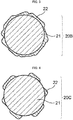
- the specimen (1.2 g) is charged in a metal case with a diameter of 13 mm (base area: 1.327 cm 2 ) and compressed with an autograph attached with a load cell (Shimadzu Corporation), having a configuration as shown in Fig. 1 , at a constant rate of 10 mm/min and a pressing force of It (surface pressure: 754 kg/cm 2 ). After the retention for 30 minutes, the pressure is released and the thickness of the specimen is measured 5 minutes after the release. The volume of the specimen is calculated based on the measured thickness, whereby the density after pressing is calculated.
- the oil absorption amount of the negative electrode material is an indicator for the proportion of voids in the negative electrode material. The greater the oil absorption amount is, the greater the proportion of the voids in the negative electrode material is.
- the negative electrode material preferably has an oil absorption amount of not less than 50 ml/100 g, more preferably not less than 55 ml/100 g, further preferably not less than 60 ml/100 g.
- the oil absorption amount of the negative electrode material can be measured by the method as described later.
- the negative electrode material includes first particles in which plural flat graphite particles are aggregated or bonded such that principal surfaces of the graphite particles are not parallel to each other.
- the negative electrode material may include a single kind of the first particles, or may include two or more kinds in combination.
- Examples of the combination of two or more kinds of first particles include a combination of two or more kinds of first particles having the same average particle size but different compositions from each other; a combination of two or more kinds of first particles having the same composition but different average particle size from each other; and a combination of two or more kinds of first particles having different compositions and different average particle size from each other.
- the configuration of the first particles is not particularly limited, as long as plural flat graphite particles are aggregated or bonded such that principal surfaces of the graphite particles are not parallel to each other.
- the first particles may include other particles, such as spherical graphite particles as mentioned later, as necessary.
- the first particles may have low-crystalline carbon that is disposed at at least a portion of a surface of the first particles.
- the flat graphite particles are non-spherical particles having an anisotropic shape.
- Examples of the flat graphite particles include scaly graphite particles, flake graphite particles and partially-vein graphite particles.
- the flat graphite particles preferably have an aspect ratio represented by A/B, in which A refers to the length of the long axis and B refers to the length of the short axis, of from 1.2 to 20, more preferably from 1.3 to 10.
- A refers to the length of the long axis
- B refers to the length of the short axis
- the aspect ratio is 1.2 or more, the contact area among the particles is increased and conductivity tends to be improved.
- the aspect ratio is 20 or less, input/output properties such as rapid charge/discharge properties of the lithium ion secondary battery tends to improve.
- the aspect ratio is obtained by observing the graphite particles and measuring the A/B of randomly selected 100 particles, and calculating the arithmetic average value of the measured values of the 100 particles.
- the length of the long axis A of a graphite particle is determined as a distance between a pair of parallel external tangent lines a1 and a2, which are most remote from each other among the parallel external tangent lines, of the projection image of the graphite particle.
- the length of the short axis B is determined as a distance between a pair of parallel external tangent lines b1 and b2, which are closest to each other among the parallel external tangent lines, of the projection image of the graphite particle.
- the term "principal surfaces of the graphite particles are not parallel to each other" refers to a state in which surfaces with the largest section of plural flat graphite particles (principal surfaces) are not oriented in a certain direction. Whether or not the principal surfaces of the graphite particles are not parallel to each other can be determined with a microscope.
- the first particles may partially include a structure in which the plural flat graphite particles are aggregated or bonded such that principal surfaces of the graphite particles are parallel to each other.
- the state in which the plural flat graphite particles are "aggregated or bonded” refers to a state in which at least two flat graphite particles are aggregated or bonded.
- the term “bonded” refers to a state in which particles are chemically bonded directly or via a carbonaceous substance.
- the term “aggregated” refers to a state in which particles maintain an aggregated state due to the particle shape or the like, without the aid of chemical bonding.
- the flat graphite particles may be aggregated or bonded via a carbonaceous substance. Examples of the carbonaceous substance include a graphitized product of the graphitizable binder. From the viewpoint of mechanical strength, a state in which two or more flat graphite particles are bonded via a carbonaceous substance is preferred. Whether or not the flat graphite particles are aggregated or bonded can be determined by observing with a scanning electron microscope, for example.
- the average particle size of the flat graphite particle is preferably from 1 ⁇ m to 50 ⁇ m, more preferably from 1 ⁇ m to 25 ⁇ m, further preferably from 1 ⁇ m to 15 ⁇ m, for example.
- the average particle size of the flat graphite particles may be measured using a laser diffraction particle distribution measurement apparatus, and is determined as a particle size at which the accumulation from the side of smaller particle size in a volume-based particle size distribution is 50% (D50).
- the flat graphite particles and the material thereof are not particularly limited, and examples thereof include artificial graphite, vein natural graphite, flake natural graphite, coke, resin, tar and pitch.
- particles of artificial graphite, natural graphite and graphite obtained from coke, which are highly crystalline and soft, are advantageous in terms of increasing the density of the negative electrode.
- the first particles may further include spherical graphite particles.
- spherical graphite particles have a higher degree of density than flat graphite particles. Therefore, by including spherical graphite particles, it is possible to increase the density of the negative electrode material, thereby reducing a pressure to be applied during a densification process. As a result, orientation of flat graphite particles in a direction along a surface of a current collector is suppressed, whereby achieving favorable migration of lithium ions.
- the flat graphite particles and the spherical graphite particles may be aggregated or bonded via a carbonaceous substance.
- the carbonaceous substance include graphite obtained by graphitization of a binder such as tar or pitch. Whether or not the first particles include spherical particles can be determined by observing the first particles with a scanning electron microscope.
- each of the first particles preferably includes the total number of flat graphite particles and spherical graphite particles of 3 or more, more preferably from 5 to 20, further preferably from 5 to 15, for example.
- the spherical graphite particles include spherical artificial graphite and spherical natural graphite. From the viewpoint of achieving a sufficient tap density of the first particles, the spherical graphite particles with a high degree of density are preferred. Specifically, spherical natural graphite obtained through a spheronization process so as to have a high tap density are preferred. Since the spherical natural graphite has a high degree of peel strength and is less likely to remove from the current collector even if the electrode is strongly pressed, it is possible to obtain a negative electrode material having a stronger peel strength by using the same as the first particles.
- the spherical graphite particles tend to be higher in density than the flat graphite particles, it is possible to reduce a pressure to be applied to the negative electrode during the densification process, and is effective for suppress the orientation of the graphite particles in a direction along the current collector.
- the average particle size of the spherical graphite particles is preferably from 5 ⁇ m to 40 ⁇ m, more preferably from 8 ⁇ m to 35 ⁇ m, further preferably from 10 ⁇ m to 30 ⁇ m, for example.
- the average particle size of the spherical graphite particles may be measured using a laser diffraction particle distribution measurement apparatus, and is determined as a particle size at which the accumulation from the side of smaller particle size in a volume-based particle size distribution is 50% (D50).
- the first particles may have low-crystallinity carbon on at least a part of a surface of the first particles.
- Existence of the low-crystallinity carbon tends to contribute to improvement in the input-output characteristics, such as rapid charge-discharge characteristics, of the lithium ion secondary battery.
- the low-crystallinity carbon refers to carbon having an R value in Raman spectrum of 0.5 or more.
- the R value of the low-crystallinity carbon is preferably from 0.5 to 1.5, more preferably from 0.7 to 1.3, further preferably from 0.8 to 1.2, for example.
- the R value is given as a value of Id/Ig, in which the Id is the intensity at a maximum peak that appears at approximately 1360 cm -1 and the Ig is the intensity at a maximum peak that appears at approximately 1580 cm -1 in the Raman spectrum obtained by laser Raman spectroscopy with an excitation wavelength of 532 nm.
- the peak that appears at approximately 1360 cm -1 is generally a peak corresponding to an amorphous structure of carbon, and is observed in a range of from 1300 cm -1 to 1400 cm -1 , for example.
- the peak that appears at approximately 1580 cm -1 is generally a peak corresponding to a graphite crystal structure of carbon, and is observed in a range of from 1530 cm -1 to 1630 cm -1 , for example.
- the R value may be measured by the following conditions using a Raman spectrum measurement apparatus (for example, NSR-1000, JASCO Corporation).
- a Raman spectrum measurement apparatus for example, NSR-1000, JASCO Corporation.
- the first particles preferably has an average particle size of from 5 ⁇ m to 40 ⁇ m, more preferably from 10 ⁇ m to 30 ⁇ m, further preferably from 10 ⁇ m to 25 ⁇ m.
- the average particle size may be measured with a laser diffraction particle size distribution measurement apparatus, and is a particle size at which the accumulation from the side of smaller particle size in the volume-based particle distribution is 50% (D50).
- examples of the method for measuring the average particle size include a method in which a sample electrode for observation is embedded in an epoxy resin, and a section of the electrode is mirror-polished and observed with a scanning electron microscope (for example, VE-7800, Keyence Corporation); and a method in which a section of the electrode is formed with an ion milling apparatus (E-3500, Hitachi High-Tech Corporation) and observed with a scanning electron microscope (for example, VE-7800, Keyence Corporation).
- a scanning electron microscope for example, VE-7800, Keyence Corporation
- the sample electrode may be prepared by the method as described above.
- the oil absorption amount of the fist particles is preferably 50 ml/100 g or more, more preferably from 50 ml/100 g to 95 ml/100 g, further preferably from 60 ml/100 g to 80 ml/100 g.
- the particles When the oil absorption amount of the fist particles is 50 ml/100 g or more, the particles have more spaces inside thereof and expansion of the negative electrode upon charging is more suppressed. Further, the cycle characteristics of the lithium ion secondary battery tends to be further improved.
- the oil absorption amount may be measured by a method described in JIS K 6217-4:2008 (Carbon Black for Rubber -basic characteristics- section IV: measurement of oil absorption amount) in which linseed oil (Kanto Kagaku Co., Ltd.) is used as the test liquid instead of dibutyl phthalate (DBP).
- JIS K 6217-4:2008 Carbon Black for Rubber -basic characteristics- section IV: measurement of oil absorption amount
- a test powder is titrated with linseed oil using a constant rate buret, and a change in the viscous characteristics is measured using a torque detector. Then, the amount of linseed oil per mass of the test powder, corresponding to a torque at 70% of the maximum torque as generated, is determined as the oil absorption amount (ml/100 g). The measurement may be performed using an absorption amount measurement apparatus available from Asahi Souken Corporation, for example.
- the first particles preferably have a degree of circularity, measured with a flow-type particle analyzer, of from 0.83 to 0.95, more preferably from 0.85 to 0.93, further preferably from 0.87 to 0.93.
- the degree of circularity may be measured by the following method.
- test tube To a 10-ml test tube, 5 ml of an aqueous solution including 0.2 % by mass of a surfactant (Liponol T/15, Lion Specialty Chemicals Co., Ltd.) were charged, and a test sample is added thereto such that the particle concentration is within 10000 to 30000 (number of particles per ⁇ l). Then, the test tube is stirred for 1 minute at a rotation rate of 2000 rpm with a vortex mixer (Corning Incorporated). Immediately after the stirring, the measurement is conducted by the following conditions using a wet flow-type particle analyzer (for example, FPIA-3000, Malvern Panalytical Ltd.)
- a wet flow-type particle analyzer for example, FPIA-3000, Malvern Panalytical Ltd.
- the tap density of the first particles is preferably from 0.70 g/cm 3 to 1.30 g/cm 3 , more preferably from 0.85 g/cm 3 to 1.20 g/cm 3 , further preferably from 0.90 g/cm 3 to 1.10 g/cm 3 .
- the tap density of the first particles may be measured by the same method for the tap density of the negative electrode material.
- the specific surface area of the first particles is preferably from 1.5 m 2 /g to 8.0 m 2 /g, more preferably from 2.0 m 2 /g to 7.0 m 2 /g, further preferably from 3.0 m 2 /g to 5.0 m 2 /g.
- the specific surface area of the first particles may be measured by the same method for the specific surface area of the negative electrode material.
- the content of the first particles with respect to the total amount of the negative electrode material is not particularly limited.
- the content of the first particles is preferably from 70% by mass to 99.5% by mass, more preferably from 80% by mass to 99% by mass, further preferably from 85% by mass to 98% by mass.
- the content of the first particles is not less than 70% by mass, expansion of the negative electrode upon charging is more suppressed, and the cycle characteristics of the lithium ion secondary battery tends to be further improved.
- the content of the first particles is not more than 99.5% by mass, the charge-discharge capacity of the lithium ion secondary battery tends to be further improved.
- the method of producing the first particles is not particularly limited.
- the method may include (a) a process of obtaining a mixture that includes a graphitizable binder and at least one selected from the group consisting of a graphitizable aggregate and graphite; and (b) a process of graphitizing the mixture.
- a mixture is obtained by mixing a graphitizable binder with at least one selected from the group consisting of a graphitizable aggregate and graphite.
- the mixture may be added with a graphitization catalyst, a fluidity-imparting agent, and the like.
- the graphitizable aggregate is not particularly limited as long as it is in the form of a powder, and examples include cokes such as fluid coke, needle coke and mosaic coke.
- cokes such as fluid coke, needle coke and mosaic coke.
- carbon black may be used.
- the graphite is not particularly limited as long as it is in the form of a powder, and examples include flaky artificial graphite, vain natural graphite, flaky natural graphite, spherical artificial graphite, and spherical natural graphite.
- graphitizable binder examples include pitch or tar of coal-type, petroleum-type or artificial, thermoplastic resins and thermosetting resins.
- the graphitization catalyst examples include a substance having a catalytic activity for graphitization, such as silicon, iron, nickel, titanium, boron, vanadium and aluminum, carbides, oxides and nitrides of these substances, and mica-like clay minerals.
- the mixture preferably includes a fluidity-imparting agent.
- a fluidity-imparting agent when the molding is performed by extrusion molding, in which the molding is performed while the mixture is in a flowable state.
- inclusion of the fluidity-imparting agent can reduce the amount of the graphitizable binder, whereby improvement in the battery properties, such as the initial charge/discharge efficiency of the negative electrode material, may be expected.
- the amount thereof with respect to 100 parts by mass of the mixture is preferably 80 parts by mass or less, more preferably 60 parts by mass or less.
- the amount of the spherical graphite particles is within the above range, it is possible to achieve an excellent balance between the effect of including flat particles and the effect of including spherical particles (i.e., exhibits a high discharge capacity, a low electrode expansion rate and favorable cycle characteristics even when the negative electrode is subjected to a densification treatment).
- the content of the graphitizable binder with respect to 100 parts by mass of the mixture obtained in process (2) is preferably from 5 parts by mass to 30 parts by mass, more preferably from 10 parts by mass to 30 parts by mass, for example.
- the method for obtaining the mixture in process (a) is not particularly limited, and may be performed using a kneader, for example.
- the mixing is preferably performed at a temperature higher than the softening point of the graphitizable binder. Specifically, when the mixing is preferably performed at from 50°C to 300°C when the graphitizable binder is pitch or tar, and at from 20°C to 100°C when the graphitizable binder is a thermosetting resin.
- the mixture obtained in process (a) is graphitized.
- components that are graphitizable in the mixture are graphitized.
- the graphitization is preferably performed in an atmosphere in which the mixture is resistant to oxidation, such as nitrogen, argon or vacuum.
- the temperature for the graphitization is not particularly limited, as long as the graphitizable components can be graphitized.
- the temperature may be 1500°C or more, 2000°C or more, 2500°C or more, or 2800°C or more.
- the upper limit of the temperature is not particularly limited, and may be 3200°C or less, for example.
- the temperature When the temperature is 1500°C or more, a change in crystals occurs may be caused. When the temperature is 2000°C or more, development of graphite crystals tends to be favorable. When the temperature is 2500°C or more, a high-capacity graphite crystals that can store more lithium ions tends to be formed, and the amount of ash tends to be suppressed due to the reduced amount of graphitization catalyst that remains after the thermal treatment. When the temperature is 3200°C or less, sublimation of a part of graphite tends to be suppressed.
- the first particles are obtained by pulverizing the product obtained by the graphitization.
- the method for the pulverization is not particularly limited, and may be performed by a known method such as a jet mill, a vibration mill, a pin mill or a hammer mill.
- the pulverized product may be subjected to classification.
- the method for the classification is not particularly limited, and may be performed by a known method using a vibration sifter, a rotary dry-type sifter or the like.
- the method for producing the negative electrode material may include, between process (a) and process (b), at least one selected from the group consisting of (c) a process of molding the mixture and (d) a process of subjecting the mixture to a thermal treatment.
- the method for molding in process (c) is not particularly limited.
- the molding may be performed by pulverizing the mixture and packing the same in a container such as a metal case.
- the mixture may be molded by extrusion molding while the mixture is in a flowable state.
- the bulk density of the mixture can be increased.
- the amount of the mixture to be introduced in the graphitization furnace can be increased, whereby the energy efficiency of the graphitization can be improved.
- the mixture includes a graphitization catalyst, a distance between the catalyst and the graphitizable aggregate is decreased, and the reaction time for graphitization becomes shortened. As a result, the energy efficiency can be improved and the effects on the environmental can be reduced. Further, since the use efficiency of the graphitization catalyst is increased, a loss due to sublimation of the unused catalyst can be reduced as a result of shortening the distance between the catalyst and the graphitizable aggregate.
- the degree of development of graphite crystals can be regulated by adjusting the conditions such as performing or not performing the molding of the mixture; the bulk density of the molded mixture; the type or the content of the graphitization catalyst; and the temperature or the time for the graphitization.
- the mixture is preferably subjected to a thermal treatment to remove volatile components from the mixture in process (d).
- the thermal treatment is more preferably performed after molding the mixture in process (c).
- the thermal treatment is preferably performed at a temperature at which the volatile components can be removed from the mixture, for example, at from 500°C to 1000°C.
- a thermal treatment may be performed on the first particles to which an organic compound is attached.
- the organic compound becomes low-crystalline carbon.
- low-crystalline carbon can be disposed at at least a part of a surface of the first particles.
- the method for attaching an organic compound to a surface of the first particles is not particularly limited, and examples thereof include a wet process of dispersing or mixing the first particles with a mixed solution in which an organic compound is dissolved or dispersed in a solvent, and then allowing the organic compound to attach to the first particles by removing the solvent; and a dry process of applying a mechanical force to a mixture obtained by mixing the first particles and a solid organic compound.
- the organic compound is not particularly limited, as long as it has an ability to turn to low-crystalline carbon by the thermal treatment (carbon precursor).
- Examples of the organic compound include petroleum pitch, naphthalene, anthracene, phenanthroline, coal tar, phenol resin and polyvinyl alcohol.
- a single kind of the organic compound may be used, or two or more kinds may be used in combination.
- the temperature for the thermal treatment on the first particles to which an organic compound is attached is not particularly limited, as long as the organic compound can be carbonized, and is preferably from 400°C to 1000°C, for example.
- the thermal treatment is preferably performed in an inert gas atmosphere, such as nitrogen.
- the negative electrode material includes second particles including silicon atoms.
- the negative electrode material may include a single kind of the second particles, or may include two or more kinds in combination.
- Examples of the combination of two or more kinds of the second particles include a combination of two or more kinds of the second particles having the same average diameter but different compositions from each other; a combination of two or more kinds of the second particles having the same composition but different average diameters from each other; and a combination of two or more kinds of the second particles having different compositions and different average diameters from each other.
- the second particles are not particularly limited, as long as silicon atoms are included therein.
- Examples of the second particles include particles including silicon, particles including a silicon compound such as silicon oxide, and particles including silicon and a silicon compound.
- the second particles are preferably particles that substantially consist of silicon or particles that substantially consist of silicon oxide, more preferably particles that substantially consist of silicon oxide.
- the term "substantially” refers to that the particles may include unintentional impurity.
- the content of the impurity in the second particles is not more than 10% by mass, preferably not more than 5% by mass, for example.
- the second particles preferably have a configuration in which silicon crystallites are dispersed in silicon oxide.
- XRD powder X-ray diffraction
- the size of the silicon crystallites is preferably from 2 nm to 8 nm, more preferably from 3 nm to 6 nm.
- the size of the silicon crystallites is not less than 2 nm, the reaction between lithium ions and silicon oxide can be controlled, and the charge-discharge efficiency of the lithium ion secondary battery tends to be further improved.
- the size of the silicon crystallites is not more than 8 nm, localization of the silicon crystallites in the silicon oxide is suppressed and lithium ions are readily dispersed in the silicon oxide, whereby a favorable charge capacity tends to be achieved.
- the X-ray diffraction measurement using CuK ⁇ line may be performed using an X-ray diffraction analyzer (for example, MultiFlex, Rigaku Corporation).
- an X-ray diffraction analyzer for example, MultiFlex, Rigaku Corporation.
- Particles having a configuration in which silicon crystallites are dispersed in silicon oxide may be obtained by, for example, causing disproportionation of silicon oxide particles by subjecting the same to a thermal treatment at a temperature of from 700°C to 1300°C in an inert atmosphere.
- a thermal treatment at a temperature of from 700°C to 1300°C in an inert atmosphere. The higher the temperature for the thermal treatment is, and the longer the time for the thermal treatment is, the size of silicone crystallites tends to increase.
- the second particles may have carbon at least at a portion of a surface thereof.
- carbon is disposed at at least a portion of a surface of the second particles, the initial capacity and the initial charge-discharge efficiency of the lithium ion secondary battery tend to be further improved.
- the content of the carbon with respect to the total amount of the second particles is preferably from 0.5% by mass to less than 5.0% by mass, more preferably from 0.5% by mass to 4.5% by mass, further preferably from 0.5% by mass to 4.0% by mass, for example.
- the content of the carbon may be measured by high-frequency sintering-infrared spectroscopy, using a carbon-sulfur simultaneous analyzer (for example, CSLS600, LECO Japan Corporation).
- a carbon-sulfur simultaneous analyzer for example, CSLS600, LECO Japan Corporation.
- the carbon disposed at at least a portion of a surface of the second particles is preferably low-crystalline carbon.
- low-crystalline carbon is disposed at at least a portion of a surface of the second particles, the charge-discharge capacity of the lithium ion secondary battery tends to be further improved.
- the R value of the second particles, having low-crystalline carbon at at least a portion of a surface thereof, is preferably from 0.5 to 1.5, more preferably from 0.7 to 1.3, further preferably from 0.8 to 1.2.
- Fig. 2 to Fig. 6 show the schematic sectional views of the exemplary configurations of the second particles.
- carbon 22 covers the entire surface of silicon oxide particle 21.
- carbon 22 covers the entire surface of silicon oxide particle 21, but not in a uniform manner.
- carbon 22 covers a portion of the surface of silicon oxide particle 21, and a portion of the surface of the silicon oxide particle 21 is exposed.
- carbon 22 is in the form of particles smaller than the silicon oxide particle 21 that exist at a surface of the silicon oxide particle 21.
- carbon 22 is in the form of particles having a flaky shape.
- the silicon oxide particle 21 is schematically described as having a spherical shape (circle in a section), the shape of the silicon oxide particle 21 is not particularly limited.
- the method for disposing carbon at at least a portion of a surface of the second particles is not particularly limited, and examples thereof include a wet method in which the second particles are dispersed or mixed in a mixed solution in which an organic compound is dissolved or dispersed in a solvent, and the organic compound is attached to the second particles by removing the solvent; and a dry method in which the second particles and a solid organic compound are mixed, and the organic compound is attached to the second particles by adding a mechanical force thereto.
- the organic compound is not particularly limited, as long as it has an ability to turn to low-crystalline carbon by a thermal treatment (carbon precursor).
- examples of the organic compound include petroleum pitch, naphthalene, anthracene, phenanthroline, coal tar, phenol resin and polyvinyl alcohol.
- a single kind of the organic compound may be used, or two or more kinds may be used in combination.
- the temperature for the thermal treatment to be performed on the second particles to which an organic compound is attached is not particularly limited as long as the organic compound can be carbonized, and is preferably from 750°C to 1300°C, for example.
- the thermal treatment is preferably performed in an inert gas atmosphere, such as nitrogen.
- the average particle size of the second particles is preferably from 0.1 ⁇ m to 20 ⁇ m, more preferably from 0.5 ⁇ m to 15 ⁇ m, further preferably from 1 ⁇ m to 15 ⁇ m, for example.
- the average particle size of the second particles may be measured using a laser diffraction particle distribution measurement apparatus, and is determined as a particle size at which the accumulation from the side of smaller particle size in a volume-based particle size distribution is 50% (D50).
- the average particle size of the second particles may be measured in the same manner as the average particle size of the first particles.
- the ratio of the average particle size of the first particles with respect to the average particle size of the second particles is preferably from 1.0 to 10.0, more preferably 1.5 to 8.0, further preferably from 1.5 to 6.0, for example.
- the second particles preferably have a tap density of from 0.7 g/cm 3 to 1.3 g/cm 3 , more preferably from 0.85 g/cm 3 to 1.25 g/cm 3 , further preferably from 0.9 g/cm 3 to 1.2 g/cm 3 .
- the tap density of the second particles may be measured in the same manner as the tap density of the negative electrode material.
- the second particles preferably have a specific surface area of 0.5 m 2 /g or more, more preferably 1.0 m 2 /g or more.
- the specific surface area of the second particles may be measured in the same manner as the specific surface area of the negative electrode material.
- the content of the second particles with respect to the total amount of the negative electrode material is preferably from 0.1% by mass to 20% by mass, more preferably from 0.5% by mass to 15% by mass, further preferably from 1% by mass to 10% by mass, for example.
- the content of the second particles is not less than 0.1% by mass, the charge-discharge capacity of the lithium ion secondary battery tends to be further improved.
- the content of the second particles is not more than 20% by mass, expansion of the negative electrode upon charging is further suppressed, and the cycle characteristics of the lithium ion secondary battery tends to be further improved.
- the negative electrode material may include particles that does not form the first particles, other than the first particles and the second particles.
- graphite particles examples include particles of artificial graphite, natural graphite, MC (mesophase carbon) and the like.
- the graphite particles may be flat graphite particles or spherical graphite particles, and may be selected according to the desired properties.
- the graphite particles may be flat graphite particles from the viewpoint of improving the cycle characteristics by improving the electroconductive contact.
- the graphite particles preferably have an average particle size of from 1 ⁇ m to 50 ⁇ m, for example. From the viewpoint of improving the electroconductive contact, the graphite particles more preferably have a smaller average particle size than the first particles, further preferably have a smaller average particle size than the second particles.
- the particle size of the flat graphite particles is preferably not more than 0.7 times as large as the average particle size of the first particles or the second particles, more preferably not more than 0.4 times as large as the average particle size of the first particles or the second particles.
- the graphite particles preferably have a tap density of from 0.25 g/cm 3 to 1.3 g/cm 3 , for example.
- the tap density is preferably as small as possible, by including graphite particles having a flat shape as much as possible. From the viewpoint of the specific surface area, the tap density is more preferably from 0.25 g/cm 3 to 0.8 g/cm 3 , further preferably from 0.3 g/cm 3 to 0.5 g/cm 3 .
- the graphite particles preferably have a specific surface area of from 0.5 m 2 /g to 25 m 2 /g.
- the specific surface area is more preferably from 7 m 2 /g to 25 m 2 /g, further preferably from 10 m 2 /g to 17 m 2 /g, when the graphite particles are natural graphite.
- the specific surface area is more preferably from 2 m 2 /g to 10 m 2 /g, further preferably from 4 m 2 /g to 7 m 2 /g, when the graphite particles are artificial graphite.
- the negative electrode may include a conduction aid other than the first particles and the second particles, as necessary.
- the conduction aid include carbon black, graphite, acetylene black, an oxide that exhibits electroconductivity, and a nitride that exhibits electroconductivity.
- the method for producing a negative electrode material for a lithium ion secondary battery includes a process of mixing the first particles, in which plural flat graphite particles are aggregated or bonded such that principal surfaces of the graphite particles are not parallel to each other, with the second particles including silicon atoms (hereinafter, also referred to as a "mixing process").
- the method for producing the negative electrode material includes a process of the first particles and the second particles as described above.
- the method for mixing the first particles and the second particles is not particularly limited, and examples thereof include a wet process and a dry process. In the mixing process, other components such as a conductive aid may be mixed with the first particles and the second particles.
- the negative electrode material slurry for a lithium ion secondary battery (hereinafter, also referred to as a "negative electrode material slurry”) includes the negative electrode material according to the disclosure, an organic binder, and a solvent. As necessary, the negative electrode material slurry may include other components such as a thickener or a conduction aid.
- the organic binder is not particularly limited, and examples thereof include styrene-butadiene copolymer (styrene-butadiene rubber), (meth)acrylic copolymers obtained by polymerization of an ethylenically unsaturated carboxylic acid ester (such as methyl(meth)acrylate, ethyl(meth)acrylate, butyl(meth)acrylate and hydroxyethyl(meth)acrylate) with an ethylenically unsaturated carboxylic acid (such as acrylic acid, methacrylic acid, itaconic acid, fumaric acid and maleic acid), and polymers such as polyvinylidene difluoride, poly(ethylene oxide), polyepichlorohydrin, polyphosphazene, polyacrylonitrile, polyimide and polyamide-imide.
- styrene-butadiene copolymer styrene-butadiene rubber
- the solvent is not particularly limited, and examples thereof include organic solvents such as N-methylpyrrolidone, dimethylacetamide, dimethylformamide and ⁇ -butyrolactone, and water.
- the negative electrode material slurry may include a thickener for adjusting the viscosity of the slurry, as necessary.
- the thickener include carboxymethyl cellulose, methyl cellulose, hydroxymethyl cellulose, ethyl cellulose, polyvinyl alcohol, polyacrylic acid and a salt thereof, oxidized starch, phosphorylated starch, and casein.
- the negative electrode material slurry may include a conduction aid, as necessary.
- the conduction aid include carbon black, graphite, acethylene black, electroconductive oxides, and electroconductive nitrides.
- the negative electrode a lithium ion secondary battery (hereinafter, also referred to as a "negative electrode”) has a current collector and a negative electrode material layer that includes the negative electrode material according to the disclosure and is formed on the current collector.
- the material and the shape of the current collector are not particularly limited, and examples thereof include a ribbon-shaped foil, a ribbon-shaped punched foil, or a ribbon-shaped mesh formed from a metal or an alloy such as aluminum, copper, nickel, titanium and stainless steel. It is also possible to use a porous material such as porous metal (foamed metal) and carbon paper.
- the method for forming a negative electrode material layer, which includes the negative electrode material according to the disclosure, on a current collector is not particularly limited, and may be performed by a known method such as metal mask printing, electrostatic coating, dip coating, spray coating, roll coating, doctor blade coating, gravure coating, and screen printing. Integration of a negative electrode material layer with a current collector may be performed by a known process such as rolling, pressing or a combination thereof.
- a thermal treatment (drying) may be performed, depending on the type of the organic binder.
- the thermal treatment may be performed in an inactive atmosphere such as helium, argon or nitrogen, or in a vacuum.
- the negative electrode Prior to the thermal treatment, the negative electrode may be subjected to a pressing treatment. By performing a pressing treatment, it is possible to adjust the density of the negative electrode.
- the density of the negative electrode is preferably from 1.5 g/cm 3 to 1.9 g/cm 3 , more preferably from 1.6 g/cm 3 to 1.8 g/cm 3 , for example. By increasing the density, it is possible to improve the capacity per volume of the negative electrode, and to improve the adhesion of the negative electrode layer to the current collector. As a result, the cycle characteristics of the lithium ion secondary battery tends to improve.
- the lithium ion secondary battery according to the disclosure has a positive electrode, an electrolyte, and the negative electrode according to the disclosure.
- the lithium-ion secondary battery has a configuration in which a negative electrode and a positive electrode are disposed to face each other via a separator, and an electrolyte is injected therein.
- the positive electrode may be prepared by forming a positive electrode layer on a current collector.
- the current collector include a ribbon-shaped foil, a ribbon-shaped punched foil, or a ribbon-shaped mesh formed from a metal or an alloy such as aluminum, titanium and stainless steel.
- the separator examples include a nonwoven fabric, a cloth, a microporous film or a combination thereof, including polyolefin such as polyethylene and polypropylene as a major component.
- an organic electrolyte solution in which a lithium salt such as LiClO 4 , LiPF 6 , LiAsF 6 , LiBF 4 or LiSO 3 CF 3 is dissolved in a non-aqueous solvent such as ethylene carbonate, propylene carbonate, butylene carbonate, vinylene carbonate, fluoroethylene carbonate, cyclopentanone, sulfolane, 3-methylsulfolane, 2,4-dimethylsulfolane, 3-methyl-1,3-oxazolidin-2-one, ⁇ -butyrolactone, dimethyl carbonate, diethyl carbonate, ethylmethyl carbonate, methylpropyl carbonate, butylmethyl carbonate, ethylpropyl carbonate, butylethyl carbonate, dipropyl carbonate, 1,2-dimethoxyethane, tetrahydrofuran, 2-methyltetrahydrofuran, 1,3-d
- an electrolyte including fluoroethylene carbonate tends to achieve a significant improvement in the cycle characteristics by forming a stable SEI (solid electrolyte interface) on a surface of the negative electrode, and is suitably used.
- the configuration of the lithium-ion secondary battery is not particularly limited, and examples thereof include a paper-shaped battery, a button-shaped battery, a coin-shaped battery, a laminate-type battery, a cylindrical battery and a rectangular battery.
- Graphite particles 1 to 7 and C1 to C3, and silicon oxide particles 1 to 4 used for the preparation of a negative electrode were prepared by the following process.
- a mixture was obtained by mixing a coke powder having an average particle size of 12 ⁇ m (55 parts by mass), tar pitch (25 parts by mass) and silicon carbide as a graphitization catalyst (20 parts by mass) and kneading for 1 hour at 100°C. Then, the mixture was molded by extrusion molding. The molded product was sintered at 1000°C in a nitrogen atmosphere. The sintered product was sintered at 2800°C in an Acheson furnace such that the graphitizable components were graphitized. The graphitized product (graphitized powder) was pulverized with a hammer mill and classified, thereby obtaining graphite particles 1 having an average particle size of 20 ⁇ m.
- graphite particles 1 included particles in which plural flat graphite particles were aggregated or bonded such that principal surfaces of the graphite particles were not parallel to each other.
- the tap density, density after pressing, oil absorption amount, degree of circularity and specific surface area of graphite particles 1 were measured by the methods as described above. The results are shown in Table 1.
- a mixture was obtained by mixing a coke powder having an average particle size of 12 ⁇ m (40 parts by mass), spherical natural graphite particles having an average particle size of 20 ⁇ m (degree of circularity: 0.91) (20 parts by mass), tar pitch (20 parts by mass) and silicon carbide as a graphitization catalyst (20 parts by mass) and kneading for 1 hour at 100°C. Then, the mixture was molded by extrusion molding. The molded product was sintered at 1000°C in a nitrogen atmosphere. The sintered product was sintered at 2800°C in an Acheson furnace such that the graphitizable components were graphitized. The graphitized product (graphitized powder) was pulverized with a hammer mill and classified, thereby obtaining graphite particles 2 having an average particle size of 23 ⁇ m.
- graphite particles 2 included particles in which plural flat graphite particles were aggregated or bonded such that principal surfaces of the graphite particles were not parallel to each other.
- the tap density, density after pressing, oil absorption amount, degree of circularity and specific surface area of graphite particles 2 are shown in Table 1.
- Graphite particles 3 having an average particle size of 18 ⁇ m were prepared in the same manner to graphite particles 2 but with different conditions for the classification.
- graphite particles 3 included particles in which plural flat graphite particles were aggregated or bonded such that principal surfaces of the graphite particles were not parallel to each other.
- the tap density, density after pressing, oil absorption amount, degree of circularity and specific surface area of graphite particles 3 are shown in Table 1.
- Graphite particles 4 having an average particle size of 10 ⁇ m were prepared in the same manner to graphite particles 2 but with different conditions for the classification.
- graphite particles 4 included particles in which plural flat graphite particles were aggregated or bonded such that principal surfaces of the graphite particles were not parallel to each other.
- the tap density, density after pressing, oil absorption amount, degree of circularity and specific surface area of graphite particles 4 are shown in Table 1.
- a mixture was obtained by mixing a coke powder having an average particle size of 12 ⁇ m (20 parts by mass), flat natural graphite particles having an average particle size of 3 ⁇ m (degree of circularity: 0.8) (20 parts by mass), spherical natural graphite particles having an average particle size of 20 ⁇ m (degree of circularity: 0.91) (20 parts by mass), tar pitch (20 parts by mass) and silicon carbide as a graphitization catalyst (20 parts by mass) and kneading for 1 hour at 100°C.
- graphite particles 5 having an average particle size of 20 ⁇ m were prepared in a similar manner to graphite particles 1.
- graphite particles 5 included particles in which plural flat graphite particles were aggregated or bonded such that principal surfaces of the graphite particles were not parallel to each other.
- the tap density, density after pressing, oil absorption amount, degree of circularity and specific surface area of graphite particles 5 are shown in Table 1.
- a mixture was obtained by mixing flat natural graphite particles having an average particle size of 3 ⁇ m (degree of circularity: 0.8) (15 parts by mass), spherical natural graphite particles having an average particle size of 15 ⁇ m (degree of circularity: 0.91) (25 parts by mass), tar pitch (25 parts by mass) and silicon carbide as a graphitization catalyst (10 parts by mass) and kneading for 1 hour at 100°C. Further, the mixture (75 parts by mass) was mixed with spherical natural graphite particles having an average particle size of 15 ⁇ m (degree of circularity: 0.91) (25 parts by mass), and sintered at 1000°C in a nitrogen atmosphere. With this sintered product, graphite particles 6 having an average particle size of 15 ⁇ m were prepared in a similar manner to graphite particles 1.
- graphite particles 6 included particles in which plural flat graphite particles were aggregated or bonded such that principal surfaces of the graphite particles were not parallel to each other.
- the tap density, density after pressing, oil absorption amount, degree of circularity and specific surface area of graphite particles 6 are shown in Table 1.
- Graphite particles 2 (70 parts by mass) and spherical natural graphite particles having an average particle size of 22 ⁇ m (degree of circularity: 0.94) (25 parts by mass) were mixed, whereby graphite particles 7 having an average particle size of 22.8 ⁇ m were obtained.
- graphite particles 7 included particles in which plural flat graphite particles were aggregated or bonded such that principal surfaces of the graphite particles were not parallel to each other.
- the tap density, density after pressing, oil absorption amount, degree of circularity and specific surface area of graphite particles 7 are shown in Table 1.
- a mixture of graphite particles 3 (96 parts by mass) and tar pitch having a softening point of 100°C (4 parts by mass) was graphitized at 1100°C, whereby graphite particles 8 having an average particle size of 18.5 ⁇ m, i.e., graphite particles 3 coated with amorphous carbon, were obtained.
- graphite particles 8 included particles in which plural flat graphite particles were aggregated or bonded such that principal surfaces of the graphite particles were not parallel to each other.
- the tap density, density after pressing, oil absorption amount, degree of circularity and specific surface area of graphite particles 8 are shown in Table 1.
- a mixture was obtained by mixing flat natural graphite particles having an average particle size of 3 ⁇ m (degree of circularity: 0.8) (5 parts by mass), spherical natural graphite particles having an average particle size of 15 ⁇ m (degree of circularity: 0.91) (55 parts by mass), tar pitch (20 parts by mass) and silicon carbide as a graphitization catalyst (20 parts by mass) and kneading for 1 hour at 100°C.
- the mixture was formed into blocks by press molding, and sintered at 1000°C in a nitrogen atmosphere. With this sintered product, graphite particles 9 having an average particle size of 17.8 ⁇ m were prepared in a similar manner to graphite particles 1.
- graphite particles 9 included particles in which plural flat graphite particles were aggregated or bonded such that principal surfaces of the graphite particles were not parallel to each other.
- the tap density, density after pressing, oil absorption amount, degree of circularity and specific surface area of graphite particles 9 are shown in Table 1.
- Spherical graphite having an average particle size of 22.0 ⁇ m (degree of circularity: 0.94) were used as graphite particles C1.
- the tap density, density after pressing, oil absorption amount, degree of circularity and specific surface area of graphite particles C1 are shown in Table 1.
- graphite particles C1 did not include particles in which plural flat graphite particles were aggregated or bonded such that principal surfaces of the graphite particles were not parallel to each other.
- Spherical graphite (92 parts by mass) and tar pitch (8 parts by mass) were mixed and sintered at not less than 1000°C, thereby obtaining graphite particles C2 coated with amorphous carbon having an average particle size of 16 ⁇ m.
- the tap density, density after pressing, oil absorption amount, degree of circularity and specific surface area of graphite particles C2 are shown in Table 1.
- graphite particles C2 did not include particles in which plural flat graphite particles were aggregated or bonded such that principal surfaces of the graphite particles were not parallel to each other.
- Spherical graphite (92 parts by mass) and tar pitch (8 parts by mass) were mixed and sintered at not less than 1000°C, thereby obtaining graphite particles C3 coated with amorphous carbon having an average particle size of 10.7 ⁇ m.
- the tap density, density after pressing, oil absorption amount, degree of circularity and specific surface area of graphite particles C3 are shown in Table 1.
- graphite particles C3 did not include particles in which plural flat graphite particles were aggregated or bonded such that principal surfaces of the graphite particles were not parallel to each other.
- Silicon oxide lumps (Kojundo Chemical Lab. Co., Ltd., 10 mm to 30 mm in size) were roughly pulverized in a mortar, thereby obtaining particles of silicon oxide. The particles were further pulverized with a vibration mill (Nitto Kagaku Co., Ltd., NB-0) and classified with a 300-mesh test sieve, thereby obtaining particles of silicon oxide having an average particle size of 10 ⁇ m.
- the obtained particles of silicon oxide (96 parts by mass) and tar pitch (fixed carbon: 50% by mass) (4 parts by mass) were mixed with a rocking mixer (Aichi Electric Co., Ltd., RM-10G) for 5 minutes, and were charged in an aluminum container and subjected to a thermal treatment at 1000°C for 5 hours in a nitrogen atmosphere. Then, the particles were pulverized in a mortar and classified with a 300-mesh test sieve, thereby obtaining silicon oxide particles 1 having an average particle size of 10.8 ⁇ m.
- the tap density and the specific surface area of silicon oxide particles 1 are shown in Table 1.
- Silicon oxide lumps (Kojundo Chemical Lab. Co., Ltd., 10 mm to 30 mm in size) were roughly pulverized in a mortar, thereby obtaining particles of silicon oxide.
- the particles were further pulverized with a vibration mill (Nitto Kagaku Co., Ltd., NB-0) and classified with a 300-mesh test sieve, thereby obtaining particles of silicon oxide having an average particle size of 5 ⁇ m.
- the obtained particles of silicon oxide (96 parts by mass) and tar pitch (fixed carbon: 50% by mass) (4 parts by mass) were mixed with a rocking mixer (Aichi Electric Co., Ltd., RM-10G) for 5 minutes, and were charged in an aluminum container and subjected to a thermal treatment at 1000°C for 5 hours in a nitrogen atmosphere. Then, the particles were pulverized in a mortar and classified with a 300-mesh test sieve, thereby obtaining silicon oxide particles 2 having an average particle size of 6.2 ⁇ m.
- the tap density and the specific surface area of silicon oxide particles 2 are shown in Table 1.
- Flaky graphite particles having an average particle size of 3 ⁇ m (KS-6, Timcal) and acetylene black (HS-100, Denka Company Limited) were used as conductive particles.
- a dispersion of the conductive particles (solid content: 25% by mass) was prepared by adding, to 800 g of water, 156 g of the flaky graphite particles, 40 g of acetylene black and 4 g of carboxymethyl cellulose, and dispersing and mixing the same with a bead mill. Then, 100 g of the dispersion of the conductive particles were added to 450 g of water, stirred with a stirrer, and 500 g of silicon oxide particles 2 were added and further stirred.
- the obtained solution in which silicon oxide particles 2 and conductive particles were dispersed, was dried at 150 °C for 12 hours in a drier. Thereafter, the remainder was pulverized in a mortar and classified with a 300-mesh test sieve, thereby obtaining particles having an average particle size of 5.7 ⁇ m (intermediary particles).
- Silicon oxide lumps (Kojundo Chemical Lab. Co., Ltd., 10 mm to 30 mm in size) were roughly pulverized in a mortar, thereby obtaining particles of silicon oxide.
- the particles were further pulverized with a vibration mill (Nitto Kagaku Co., Ltd., NB-0) and classified with a 300-mesh test sieve, thereby obtaining particles of silicon oxide having an average particle size of 0.7 ⁇ m.
- the obtained particles of silicon oxide (96 parts by mass) and tar pitch (fixed carbon: 50% by mass) (4 parts by mass) were mixed with a rocking mixer (Aichi Electric Co., Ltd., RM-10G) for 5 minutes, and were charged in an aluminum container and subjected to a thermal treatment at 1000°C for 5 hours in a nitrogen atmosphere. Then, the particles were pulverized in a mortar and classified with a 300-mesh test sieve, thereby obtaining silicon oxide particles having an average particle size of 0.8 ⁇ m (intermediary particles).
- Flat graphite particles having an average particle size of 3.3 ⁇ m were used as flat graphite particles 1.
- the tap density, density after pressing, oil absorption amount, degree of circularity and specific surface area of flat graphite particles 1 are shown in Table 1. Further, the XRD peak intensity ratio, R value and oxidation weight reduction rate are shown in Table 1.
- Flat graphite particles having an average particle size of 8.1 ⁇ m (KS-6, Timcal) were used as flat graphite particles 2.
- the tap density, density after pressing, oil absorption amount, degree of circularity and specific surface area of flat graphite particles 2 are shown in Table 1. Further, the XRD peak intensity ratio, R value and oxidation weight reduction rate are shown in Table 1.
- a negative electrode material of Example 1 was prepared by mixing graphite particles 1 (95 parts by mass) and silicon oxide particles 1 (5 parts by mass). The specific surface area and the tap density of the negative electrode material are shown in Table 2. The measurement of the specific surface area and the tap density was performed by the methods as described above.
- a uniform slurry was prepared by mixing the negative electrode material prepared above (97.6 parts by mass), carboxymethyl cellulose (CMC) (1.2 parts by mass) and styrene-butadiene rubber (SBR) (1.2 parts by mass).
- the slurry was applied onto a glossy surface of an electrolyte copper foil to form a layer at an amount of 10 g/cm 2 , and subjected to preliminary drying at 90°C for 2 hours. Then, the layer was pressed with a roll so as to adjust the density to 1.65 g/cm 3 . Thereafter, the layer was cured by drying in vacuum at 120°C for 4 hours, thereby obtaining a negative electrode.
- a 2016-type coin cell was prepared using the negative electrode as prepared above, metallic lithium as a counter electrode, a mixed solution of ethylene carbonate/ethyl methyl carbonate (3:7 by volume) and vinylene carbonate (VC) (1.0% by mass) containing 1M of LiPF 6 as an electrolyte, a polyethylene porous film with 25 ⁇ m in thickness as a separator, and a copper sheet with 250 ⁇ m in thickness as a spacer.
- VC vinylene carbonate
- the cell was charged with a constant current of 0.45 mA/cm 2 to 0V, and further charged at a constant voltage of 0V until the current was damped to a value equivalent to 0.09 mA/cm 2 , and the initial charge capacity (mAh/g) was measured.
- the cell was discharged at 0.45 mA/cm 2 to 1.5V, and the initial discharge capacity (mAh/g) was measured. The measured capacity was converted to a value per mass of the negative electrode material.
- Capacity maintenance ratio (%) (discharge capacity at 10th cycle / discharge capacity at 1st cycle) ⁇ 100
- a negative electrode material of Example 2 was prepared by mixing graphite particles 2 (95 parts by mass) and silicon oxide particles 1 (5 parts by mass). The specific surface area and the tap density of the negative electrode material are shown in Table 2.
- a negative electrode and a lithium ion secondary battery were prepared and evaluated in a similar manner to Example 1, using the negative electrode material obtained in Example 2. The results are shown in Table 2.
- a negative electrode material of Example 3 was prepared by mixing graphite particles 3 (90 parts by mass) and silicon oxide particles 2 (10 parts by mass). The specific surface area and the tap density of the negative electrode material are shown in Table 2.
- a negative electrode and a lithium ion secondary battery were prepared and evaluated in a similar manner to Example 1, using the negative electrode material obtained in Example 3. The results are shown in Table 2.
- a negative electrode material of Example 4 was prepared by mixing graphite particles 4 (85 parts by mass) and silicon oxide particles 3 (15 parts by mass). The specific surface area and the tap density of the negative electrode material are shown in Table 2.
- a negative electrode and a lithium ion secondary battery were prepared and evaluated in a similar manner to Example 1, using the negative electrode material obtained in Example 4. The results are shown in Table 2.
- a negative electrode material of Example 5 was prepared by mixing graphite particles 5 (95 parts by mass) and silicon oxide particles 4 (5 parts by mass). The specific surface area and the tap density of the negative electrode material are shown in Table 2.
- a negative electrode and a lithium ion secondary battery were prepared and evaluated in a similar manner to Example 1, using the negative electrode material obtained in Example 5. The results are shown in Table 2.
- a negative electrode material of Example 6 was prepared by mixing graphite particles 6 (95 parts by mass) and silicon oxide particles 3 (5 parts by mass). The specific surface area and the tap density of the negative electrode material are shown in Table 2.
- a negative electrode and a lithium ion secondary battery were prepared and evaluated in a similar manner to Example 1, using the negative electrode material obtained in Example 6. The results are shown in Table 2.
- a negative electrode material of Example 7 was prepared by mixing graphite particles 7 (95 parts by mass) and silicon oxide particles 1 (5 parts by mass). The specific surface area and the tap density of the negative electrode material are shown in Table 2.
- a negative electrode and a lithium ion secondary battery were prepared and evaluated in a similar manner to Example 1, using the negative electrode material obtained in Example 7. The results are shown in Table 2.
- a negative electrode material of Example 8 was prepared by mixing graphite particles 8 (95 parts by mass) and silicon oxide particles 1 (5 parts by mass). The specific surface area and the tap density of the negative electrode material are shown in Table 2.
- a negative electrode and a lithium ion secondary battery were prepared and evaluated in a similar manner to Example 1, using the negative electrode material obtained in Example 8. The results are shown in Table 2.
- a negative electrode material of Example 9 was prepared by mixing graphite particles 9 (70 parts by mass), silicon oxide particles 3 (5 parts by mass) and flat graphite particles having an average particle size of 3 ⁇ m (KS-6, Timcal) (25 parts by mass).
- the specific surface area and the tap density of the negative electrode material are shown in Table 2.
- a negative electrode and a lithium ion secondary battery were prepared and evaluated in a similar manner to Example 1, using the negative electrode material obtained in Example 9. The results are shown in Table 2.
- a negative electrode material of Example 10 was prepared by mixing graphite particles 2 (85 parts by mass), silicon oxide particles 1 (5 parts by mass) and flat graphite particles having an average particle size of 8 ⁇ m (10 parts by mass).
- the specific surface area and the tap density of the negative electrode material are shown in Table 2.
- a negative electrode and a lithium ion secondary battery were prepared and evaluated in a similar manner to Example 1, using the negative electrode material obtained in Example 10. The results are shown in Table 2.
- a negative electrode material of Comparative Example 1 was prepared by mixing graphite particles C1 (95 parts by mass) and silicon oxide particles 1 (5 parts by mass). The specific surface area and the tap density of the negative electrode material are shown in Table 2.
- a negative electrode and a lithium ion secondary battery were prepared and evaluated in a similar manner to Example 1, using the negative electrode material obtained in Comparative Example 1. The results are shown in Table 2.
- a negative electrode material of Comparative Example 2 was prepared by mixing graphite particles C2 (95 parts by mass) and silicon oxide particles 3 (5 parts by mass). The specific surface area and the tap density of the negative electrode material are shown in Table 2.
- a negative electrode and a lithium ion secondary battery were prepared and evaluated in a similar manner to Example 1, using the negative electrode material obtained in Comparative Example 2. The results are shown in Table 2.
- a negative electrode material of Comparative Example 3 was prepared by mixing graphite particles C3 (90 parts by mass) and silicon oxide particles 3 (10 parts by mass). The specific surface area and the tap density of the negative electrode material are shown in Table 2.
- a negative electrode and a lithium ion secondary battery were prepared and evaluated in a similar manner to Example 1, using the negative electrode material obtained in Comparative Example 3. The results are shown in Table 2.
- Particles in which graphite particles and silicon oxide particles were compounded via a carbonized product of an organic substance were prepared using graphite particles C2 (90 parts by mass) and silicon oxide particles 2 (10 parts by mass) as a negative electrode material of Comparative Example 4.
- the specific surface area and the tap density of the negative electrode material are shown in Table 2.
- the compounding of graphite particles and silicon oxide particles was performed by sintering a mixture of spherical graphite particles used for the preparation of graphite particles C2 (82.8 parts by mass), tar pitch (7.6 parts by mass) and silicon oxide particles 2 (9.6 parts by mass) at 1000°C and pulverizing the same.
- a negative electrode and a lithium ion secondary battery were prepared and evaluated in a similar manner to Example 1, using the negative electrode material obtained in Comparative Example 4. The results are shown in Table 2.
- a negative electrode and a lithium ion secondary battery were prepared and evaluated in a similar manner to Example 1, using the negative electrode material obtained in Comparative Example 5. The results are shown in Table 2.
- Table 1 Graphite particles 1 2 3 4 5 6 7 8 9 C1 C2 C3 Average particle size [ ⁇ m] 20.0 23.0 18.0 10.0 20.0 15.0 22.8 18.5 17.8 22.0 16.0 10.7 Tap densitiy [g/cm 3 ] 0.82 0.92 0.79 0.72 0.90 0.95 1.00 0.92 1.06 1.02 1.15 0.97 Density after pressing [g/cm 3 ] 1.98 1.92 1.88 1.78 1.73 1.72 1.90 1.55 1.50 1.70 1.65 1.55 Oil absorption amount [ml/100g] 63 62 77 92 65 55 58 70 52 50 48 55 Degree of circularity [-] 0.86 ⁇ 0.89 0.88 ⁇ 0.91 0.89 ⁇ 0.92 0.90 ⁇ 0.93 0.86 ⁇ 0.89 0.90 ⁇ 0.92 0.92 ⁇ 0.94 0.89 ⁇ 0.
- 20A second particle
- 20B second particle
- 20C second particle
- 20D second particle
- 20E second particle
- 21 silicon oxide particle
- 22 carbon
Landscapes
- Chemical & Material Sciences (AREA)
- Chemical Kinetics & Catalysis (AREA)
- Electrochemistry (AREA)
- General Chemical & Material Sciences (AREA)
- Engineering & Computer Science (AREA)
- Materials Engineering (AREA)
- Manufacturing & Machinery (AREA)
- Inorganic Chemistry (AREA)
- Composite Materials (AREA)
- Battery Electrode And Active Subsutance (AREA)
Applications Claiming Priority (1)
| Application Number | Priority Date | Filing Date | Title |
|---|---|---|---|
| PCT/JP2018/012982 WO2019186828A1 (fr) | 2018-03-28 | 2018-03-28 | Matériau d'électrode négative servant à un accumulateur au lithium-ion, procédé de production de matériau d'électrode négative servant à un accumulateur au lithium-ion, électrode négative destinée à un accumulateur au lithium-ion au lithium-ion et accumulateur au lithium-ion |
Publications (3)
| Publication Number | Publication Date |
|---|---|
| EP3780184A1 true EP3780184A1 (fr) | 2021-02-17 |
| EP3780184A4 EP3780184A4 (fr) | 2021-10-20 |
| EP3780184B1 EP3780184B1 (fr) | 2024-06-26 |
Family
ID=68058699
Family Applications (1)
| Application Number | Title | Priority Date | Filing Date |
|---|---|---|---|
| EP18912877.0A Active EP3780184B1 (fr) | 2018-03-28 | 2018-03-28 | Matériau d'électrode négative servant à un accumulateur au lithium-ion, procédé de production de matériau d'électrode négative servant à un accumulateur au lithium-ion, électrode négative destinée à un accumulateur au lithium-ion au lithium-ion et accumulateur au lithium-ion |
Country Status (3)
| Country | Link |
|---|---|
| EP (1) | EP3780184B1 (fr) |
| JP (1) | JP7226431B2 (fr) |
| WO (1) | WO2019186828A1 (fr) |
Families Citing this family (2)
| Publication number | Priority date | Publication date | Assignee | Title |
|---|---|---|---|---|
| WO2022168170A1 (fr) * | 2021-02-02 | 2022-08-11 | 昭和電工マテリアルズ株式会社 | Matériau d'électrode négative pour batterie secondaire au lithium-ion, composition de matériau d'électrode négative pour batterie secondaire au lithium-ion, électrode négative pour batterie secondaire au lithium-ion et batterie secondaire au lithium-ion |
| JPWO2023139662A1 (fr) * | 2022-01-18 | 2023-07-27 |
Family Cites Families (11)
| Publication number | Priority date | Publication date | Assignee | Title |
|---|---|---|---|---|
| JP3321782B2 (ja) * | 1996-12-26 | 2002-09-09 | 日立化成工業株式会社 | リチウム二次電池負極用黒鉛粒子 |
| JP4040606B2 (ja) * | 2003-06-06 | 2008-01-30 | Jfeケミカル株式会社 | リチウムイオン二次電池用負極材料およびその製造方法、ならびにリチウムイオン二次電池用負極およびリチウムイオン二次電池 |
| JP5563743B2 (ja) * | 2008-03-28 | 2014-07-30 | 日立化成株式会社 | リチウムイオン二次電池負極用炭素材料、それを用いたリチウムイオン二次電池用負極合剤及びリチウムイオン二次電池 |
| TWI536646B (zh) | 2010-12-10 | 2016-06-01 | 日立化成股份有限公司 | 鋰離子二次電池用負極材料及其製造方法、鋰離子二次電池用負極及鋰離子二次電池 |
| JP6087648B2 (ja) * | 2012-05-14 | 2017-03-01 | Jfeケミカル株式会社 | 複合黒鉛質材料及びその製造方法、リチウムイオン二次電池用負極材料、リチウムイオン二次電池用負極並びにリチウムイオン二次電池 |
| JP2014067583A (ja) * | 2012-09-26 | 2014-04-17 | Sanyo Electric Co Ltd | 非水電解質二次電池 |
| JP6201294B2 (ja) * | 2012-11-01 | 2017-09-27 | トヨタ自動車株式会社 | 非水電解質二次電池の負極 |
| JP2015170542A (ja) * | 2014-03-10 | 2015-09-28 | 三洋電機株式会社 | 非水電解質二次電池 |
| KR101836026B1 (ko) * | 2014-03-25 | 2018-03-07 | 히타치가세이가부시끼가이샤 | 리튬 이온 이차 전지용 부극재, 리튬 이온 이차 전지용 부극재의 제조 방법, 리튬 이온 이차 전지용 부극재 슬러리, 리튬 이온 이차 전지용 부극 및 리튬 이온 이차 전지 |
| JP2015165510A (ja) * | 2015-05-18 | 2015-09-17 | 日立化成株式会社 | リチウムイオン二次電池用負極、およびリチウムイオン二次電池 |
| CN107710467B (zh) * | 2015-07-02 | 2021-07-09 | 昭和电工株式会社 | 锂离子电池用负极材料和其用途 |
-
2018
- 2018-03-28 JP JP2020508661A patent/JP7226431B2/ja active Active
- 2018-03-28 WO PCT/JP2018/012982 patent/WO2019186828A1/fr unknown
- 2018-03-28 EP EP18912877.0A patent/EP3780184B1/fr active Active
Also Published As
| Publication number | Publication date |
|---|---|
| EP3780184A4 (fr) | 2021-10-20 |
| JPWO2019186828A1 (ja) | 2021-03-18 |
| JP7226431B2 (ja) | 2023-02-21 |
| WO2019186828A1 (fr) | 2019-10-03 |
| EP3780184B1 (fr) | 2024-06-26 |
Similar Documents
| Publication | Publication Date | Title |
|---|---|---|
| EP3133678B1 (fr) | Matériau d'électrode négative pour batterie au lithium-ion, et son utilisation | |
| EP3131143B1 (fr) | Matériau d'électrode négative pour batterie secondaire lithium-ion, procédé de fabrication de matériau d'électrode négative pour batterie secondaire au lithium-ion, suspension concentrée de matériau d'électrode négative pour batterie secondaire lithium-ion, électrode négative pour batterie secondaire lithium-ion, et batterie secondaire lithium-ion | |
| EP2913872B1 (fr) | Matériau d'électrode négative pour batterie secondaire au lithium-ion, électrode négative pour batterie secondaire au lithium-ion, et batterie secondaire au lithium-ion | |
| JP7192499B2 (ja) | 非水系二次電池用負極材、非水系二次電池用負極及び非水系二次電池 | |
| KR100722071B1 (ko) | 리튬이차전지용음극재료,그의제조방법및그를이용한이차전지 | |
| JP5346962B2 (ja) | 黒鉛質材料とその製造方法、リチウムイオン二次電池用負極材料、リチウムイオン二次電池用負極およびリチウムイオン二次電池 | |
| WO2018179813A1 (fr) | Matériau actif d'électrode négative pour batterie secondaire lithium-ion, électrode négative pour batterie secondaire lithium-ion, et batterie secondaire lithium-ion | |
| JP6511726B2 (ja) | リチウムイオン二次電池用負極材料、リチウムイオン二次電池用負極及びリチウムイオン二次電池 | |
| WO2019150511A1 (fr) | Matériau actif d'électrode négative pour batterie secondaire au lithium-ion, électrode négative pour batterie secondaire au lithium-ion et batterie secondaire au lithium-ion | |
| JP7334735B2 (ja) | 非水系二次電池用負極材、非水系二次電池用負極及び非水系二次電池 | |
| JP3305995B2 (ja) | リチウム二次電池負極用黒鉛粒子 | |
| WO2019150512A1 (fr) | Matériau actif d'électrode négative pour batterie secondaire au lithium-ion, électrode négative pour batterie secondaire au lithium-ion et batterie secondaire au lithium-ion | |
| EP4287305A1 (fr) | Matériau d'électrode négative pour batterie secondaire au lithium-ion, son procédé d'évaluation, son procédé de fabrication, électrode négative pour batterie secondaire au lithium-ion et batterie secondaire au lithium-ion | |
| JP2007173156A (ja) | リチウムイオン二次電池用負極材料、リチウムイオン二次電池用負極およびリチウムイオン二次電池 | |
| WO2019150513A1 (fr) | Matériau actif d'électrode négative pour batterie secondaire au lithium-ion, électrode négative pour batterie secondaire au lithium-ion et batterie secondaire au lithium-ion | |
| WO2022270539A1 (fr) | Particules de carbone composites et leur utilisation | |
| EP3780184B1 (fr) | Matériau d'électrode négative servant à un accumulateur au lithium-ion, procédé de production de matériau d'électrode négative servant à un accumulateur au lithium-ion, électrode négative destinée à un accumulateur au lithium-ion au lithium-ion et accumulateur au lithium-ion | |
| EP4099442A1 (fr) | Matériau d'électrode négative pour cellule secondaire au lithium-ion, son procédé de fabrication, électrode négative pour cellule secondaire au lithium-ion et cellule secondaire au lithium-ion | |
| JP3321782B2 (ja) | リチウム二次電池負極用黒鉛粒子 | |
| WO2021005689A1 (fr) | Matériau actif d'électrode négative pour batterie secondaire au lithium-ion, électrode négative pour batterie secondaire au lithium-ion, batterie secondaire au lithium-ion et procédé de fabrication de matériau actif d'électrode négative pour batterie secondaire au lithium-ion | |
| JP5990872B2 (ja) | リチウム二次電池負極材、リチウム二次電池用負極及びリチウム二次電池 | |
| EP4131488A1 (fr) | Matière active composite pour batterie secondaire au lithium, composition d'électrode pour batterie secondaire au lithium, électrode de batterie secondaire au lithium et procédé de fabrication de matière active composite pour batterie secondaire au lithium | |
| KR20200121321A (ko) | 탄소질 입자, 리튬 이온 이차 전지용 음극재, 리튬 이온 이차 전지용 음극, 및 리튬 이온 이차 전지 |
Legal Events
| Date | Code | Title | Description |
|---|---|---|---|
| STAA | Information on the status of an ep patent application or granted ep patent |
Free format text: STATUS: THE INTERNATIONAL PUBLICATION HAS BEEN MADE |
|
| PUAI | Public reference made under article 153(3) epc to a published international application that has entered the european phase |
Free format text: ORIGINAL CODE: 0009012 |
|
| STAA | Information on the status of an ep patent application or granted ep patent |
Free format text: STATUS: REQUEST FOR EXAMINATION WAS MADE |
|
| 17P | Request for examination filed |
Effective date: 20201026 |
|
| AK | Designated contracting states |
Kind code of ref document: A1 Designated state(s): AL AT BE BG CH CY CZ DE DK EE ES FI FR GB GR HR HU IE IS IT LI LT LU LV MC MK MT NL NO PL PT RO RS SE SI SK SM TR |
|
| AX | Request for extension of the european patent |
Extension state: BA ME |
|
| RAP3 | Party data changed (applicant data changed or rights of an application transferred) |
Owner name: SHOWA DENKO MATERIALS CO., LTD. |
|
| RIN1 | Information on inventor provided before grant (corrected) |
Inventor name: KOMATSU, NAOYA Inventor name: TSUCHIYA, HIDEYUKI |
|
| DAV | Request for validation of the european patent (deleted) | ||
| DAX | Request for extension of the european patent (deleted) | ||
| STAA | Information on the status of an ep patent application or granted ep patent |
Free format text: STATUS: EXAMINATION IS IN PROGRESS |
|
| A4 | Supplementary search report drawn up and despatched |
Effective date: 20210916 |
|
| RIC1 | Information provided on ipc code assigned before grant |
Ipc: H01M 4/62 20060101ALN20210910BHEP Ipc: H01M 4/02 20060101ALN20210910BHEP Ipc: H01M 10/0525 20100101ALN20210910BHEP Ipc: H01M 4/36 20060101ALI20210910BHEP Ipc: H01M 4/04 20060101ALI20210910BHEP Ipc: H01M 4/1393 20100101ALI20210910BHEP Ipc: H01M 4/1391 20100101ALI20210910BHEP Ipc: H01M 4/133 20100101ALI20210910BHEP Ipc: H01M 4/131 20100101ALI20210910BHEP Ipc: H01M 4/48 20100101ALI20210910BHEP Ipc: H01M 4/587 20100101AFI20210910BHEP |
|
| 17Q | First examination report despatched |
Effective date: 20210928 |
|
| RAP3 | Party data changed (applicant data changed or rights of an application transferred) |
Owner name: RESONAC CORPORATION |
|
| RIN1 | Information on inventor provided before grant (corrected) |
Inventor name: KOMATSU, NAOYA Inventor name: TSUCHIYA, HIDEYUKI |
|
| GRAP | Despatch of communication of intention to grant a patent |
Free format text: ORIGINAL CODE: EPIDOSNIGR1 |
|
| STAA | Information on the status of an ep patent application or granted ep patent |
Free format text: STATUS: GRANT OF PATENT IS INTENDED |
|
| RIC1 | Information provided on ipc code assigned before grant |
Ipc: H01M 4/62 20060101ALN20240110BHEP Ipc: H01M 4/02 20060101ALN20240110BHEP Ipc: H01M 10/0525 20100101ALN20240110BHEP Ipc: H01M 4/38 20060101ALI20240110BHEP Ipc: H01M 4/36 20060101ALI20240110BHEP Ipc: H01M 4/04 20060101ALI20240110BHEP Ipc: H01M 4/1393 20100101ALI20240110BHEP Ipc: H01M 4/1391 20100101ALI20240110BHEP Ipc: H01M 4/133 20100101ALI20240110BHEP Ipc: H01M 4/131 20100101ALI20240110BHEP Ipc: H01M 4/48 20100101ALI20240110BHEP Ipc: H01M 4/587 20100101AFI20240110BHEP |
|
| INTG | Intention to grant announced |
Effective date: 20240125 |
|
| RAP3 | Party data changed (applicant data changed or rights of an application transferred) |
Owner name: RESONAC CORPORATION |
|
| GRAS | Grant fee paid |
Free format text: ORIGINAL CODE: EPIDOSNIGR3 |
|
| GRAA | (expected) grant |
Free format text: ORIGINAL CODE: 0009210 |
|
| STAA | Information on the status of an ep patent application or granted ep patent |
Free format text: STATUS: THE PATENT HAS BEEN GRANTED |
|
| AK | Designated contracting states |
Kind code of ref document: B1 Designated state(s): AL AT BE BG CH CY CZ DE DK EE ES FI FR GB GR HR HU IE IS IT LI LT LU LV MC MK MT NL NO PL PT RO RS SE SI SK SM TR |
|
| REG | Reference to a national code |
Ref country code: GB Ref legal event code: FG4D |
|
| REG | Reference to a national code |
Ref country code: CH Ref legal event code: EP |
|
| REG | Reference to a national code |
Ref country code: DE Ref legal event code: R096 Ref document number: 602018071157 Country of ref document: DE |