EP3776359B1 - Moyen d'identification de véhicule - Google Patents
Moyen d'identification de véhicule Download PDFInfo
- Publication number
- EP3776359B1 EP3776359B1 EP19718246.2A EP19718246A EP3776359B1 EP 3776359 B1 EP3776359 B1 EP 3776359B1 EP 19718246 A EP19718246 A EP 19718246A EP 3776359 B1 EP3776359 B1 EP 3776359B1
- Authority
- EP
- European Patent Office
- Prior art keywords
- plate body
- identification means
- antenna
- nfc transponder
- vehicle identification
- Prior art date
- Legal status (The legal status is an assumption and is not a legal conclusion. Google has not performed a legal analysis and makes no representation as to the accuracy of the status listed.)
- Active
Links
- 230000001681 protective effect Effects 0.000 claims description 30
- 239000012876 carrier material Substances 0.000 claims description 27
- 239000000853 adhesive Substances 0.000 claims description 15
- 150000001875 compounds Chemical class 0.000 claims description 14
- 239000004020 conductor Substances 0.000 claims description 11
- 239000011248 coating agent Substances 0.000 claims description 9
- 238000000576 coating method Methods 0.000 claims description 8
- 229910052751 metal Inorganic materials 0.000 claims description 6
- 239000002184 metal Substances 0.000 claims description 6
- 239000012811 non-conductive material Substances 0.000 claims description 6
- NIXOWILDQLNWCW-UHFFFAOYSA-N acrylic acid group Chemical group C(C=C)(=O)O NIXOWILDQLNWCW-UHFFFAOYSA-N 0.000 claims description 5
- 229910052782 aluminium Inorganic materials 0.000 claims description 5
- XAGFODPZIPBFFR-UHFFFAOYSA-N aluminium Chemical compound [Al] XAGFODPZIPBFFR-UHFFFAOYSA-N 0.000 claims description 5
- 239000011324 bead Substances 0.000 claims description 5
- 239000013528 metallic particle Substances 0.000 claims description 5
- 239000011347 resin Substances 0.000 claims description 4
- 229920005989 resin Polymers 0.000 claims description 4
- 238000004891 communication Methods 0.000 claims description 3
- 239000011810 insulating material Substances 0.000 claims description 2
- 238000004804 winding Methods 0.000 claims description 2
- 238000007789 sealing Methods 0.000 claims 4
- 239000004411 aluminium Substances 0.000 claims 2
- 241000237519 Bivalvia Species 0.000 claims 1
- 235000020639 clam Nutrition 0.000 claims 1
- 239000010410 layer Substances 0.000 description 18
- 230000005672 electromagnetic field Effects 0.000 description 13
- 238000005266 casting Methods 0.000 description 10
- 230000008878 coupling Effects 0.000 description 7
- 238000010168 coupling process Methods 0.000 description 7
- 238000005859 coupling reaction Methods 0.000 description 7
- 230000007613 environmental effect Effects 0.000 description 6
- 238000002372 labelling Methods 0.000 description 4
- 239000000969 carrier Substances 0.000 description 3
- 239000000463 material Substances 0.000 description 3
- 230000005540 biological transmission Effects 0.000 description 2
- 230000006378 damage Effects 0.000 description 2
- 238000004049 embossing Methods 0.000 description 2
- 230000010354 integration Effects 0.000 description 2
- 238000002955 isolation Methods 0.000 description 2
- 239000004922 lacquer Substances 0.000 description 2
- 238000000034 method Methods 0.000 description 2
- 238000010146 3D printing Methods 0.000 description 1
- 230000001070 adhesive effect Effects 0.000 description 1
- 230000001066 destructive effect Effects 0.000 description 1
- 238000010292 electrical insulation Methods 0.000 description 1
- 230000006870 function Effects 0.000 description 1
- 230000001939 inductive effect Effects 0.000 description 1
- 238000004519 manufacturing process Methods 0.000 description 1
- 230000003287 optical effect Effects 0.000 description 1
- 230000035515 penetration Effects 0.000 description 1
- 230000000704 physical effect Effects 0.000 description 1
- 229920000642 polymer Polymers 0.000 description 1
- 238000007639 printing Methods 0.000 description 1
- 239000011241 protective layer Substances 0.000 description 1
- 238000004080 punching Methods 0.000 description 1
- 230000003595 spectral effect Effects 0.000 description 1
- 230000003313 weakening effect Effects 0.000 description 1
Images


Classifications
-
- G—PHYSICS
- G07—CHECKING-DEVICES
- G07C—TIME OR ATTENDANCE REGISTERS; REGISTERING OR INDICATING THE WORKING OF MACHINES; GENERATING RANDOM NUMBERS; VOTING OR LOTTERY APPARATUS; ARRANGEMENTS, SYSTEMS OR APPARATUS FOR CHECKING NOT PROVIDED FOR ELSEWHERE
- G07C5/00—Registering or indicating the working of vehicles
- G07C5/008—Registering or indicating the working of vehicles communicating information to a remotely located station
-
- G—PHYSICS
- G06—COMPUTING; CALCULATING OR COUNTING
- G06K—GRAPHICAL DATA READING; PRESENTATION OF DATA; RECORD CARRIERS; HANDLING RECORD CARRIERS
- G06K19/00—Record carriers for use with machines and with at least a part designed to carry digital markings
- G06K19/06—Record carriers for use with machines and with at least a part designed to carry digital markings characterised by the kind of the digital marking, e.g. shape, nature, code
- G06K19/067—Record carriers with conductive marks, printed circuits or semiconductor circuit elements, e.g. credit or identity cards also with resonating or responding marks without active components
- G06K19/07—Record carriers with conductive marks, printed circuits or semiconductor circuit elements, e.g. credit or identity cards also with resonating or responding marks without active components with integrated circuit chips
- G06K19/0723—Record carriers with conductive marks, printed circuits or semiconductor circuit elements, e.g. credit or identity cards also with resonating or responding marks without active components with integrated circuit chips the record carrier comprising an arrangement for non-contact communication, e.g. wireless communication circuits on transponder cards, non-contact smart cards or RFIDs
- G06K19/0724—Record carriers with conductive marks, printed circuits or semiconductor circuit elements, e.g. credit or identity cards also with resonating or responding marks without active components with integrated circuit chips the record carrier comprising an arrangement for non-contact communication, e.g. wireless communication circuits on transponder cards, non-contact smart cards or RFIDs the arrangement being a circuit for communicating at a plurality of frequencies, e.g. for managing time multiplexed communication over at least two antennas of different types
-
- B—PERFORMING OPERATIONS; TRANSPORTING
- B60—VEHICLES IN GENERAL
- B60R—VEHICLES, VEHICLE FITTINGS, OR VEHICLE PARTS, NOT OTHERWISE PROVIDED FOR
- B60R13/00—Elements for body-finishing, identifying, or decorating; Arrangements or adaptations for advertising purposes
- B60R13/10—Registration, licensing, or like devices
-
- G—PHYSICS
- G06—COMPUTING; CALCULATING OR COUNTING
- G06K—GRAPHICAL DATA READING; PRESENTATION OF DATA; RECORD CARRIERS; HANDLING RECORD CARRIERS
- G06K19/00—Record carriers for use with machines and with at least a part designed to carry digital markings
- G06K19/06—Record carriers for use with machines and with at least a part designed to carry digital markings characterised by the kind of the digital marking, e.g. shape, nature, code
- G06K19/067—Record carriers with conductive marks, printed circuits or semiconductor circuit elements, e.g. credit or identity cards also with resonating or responding marks without active components
- G06K19/07—Record carriers with conductive marks, printed circuits or semiconductor circuit elements, e.g. credit or identity cards also with resonating or responding marks without active components with integrated circuit chips
- G06K19/077—Constructional details, e.g. mounting of circuits in the carrier
- G06K19/07749—Constructional details, e.g. mounting of circuits in the carrier the record carrier being capable of non-contact communication, e.g. constructional details of the antenna of a non-contact smart card
- G06K19/07758—Constructional details, e.g. mounting of circuits in the carrier the record carrier being capable of non-contact communication, e.g. constructional details of the antenna of a non-contact smart card arrangements for adhering the record carrier to further objects or living beings, functioning as an identification tag
-
- G—PHYSICS
- G06—COMPUTING; CALCULATING OR COUNTING
- G06K—GRAPHICAL DATA READING; PRESENTATION OF DATA; RECORD CARRIERS; HANDLING RECORD CARRIERS
- G06K19/00—Record carriers for use with machines and with at least a part designed to carry digital markings
- G06K19/06—Record carriers for use with machines and with at least a part designed to carry digital markings characterised by the kind of the digital marking, e.g. shape, nature, code
- G06K19/067—Record carriers with conductive marks, printed circuits or semiconductor circuit elements, e.g. credit or identity cards also with resonating or responding marks without active components
- G06K19/07—Record carriers with conductive marks, printed circuits or semiconductor circuit elements, e.g. credit or identity cards also with resonating or responding marks without active components with integrated circuit chips
- G06K19/077—Constructional details, e.g. mounting of circuits in the carrier
- G06K19/07749—Constructional details, e.g. mounting of circuits in the carrier the record carrier being capable of non-contact communication, e.g. constructional details of the antenna of a non-contact smart card
- G06K19/07773—Antenna details
- G06K19/07786—Antenna details the antenna being of the HF type, such as a dipole
-
- H—ELECTRICITY
- H04—ELECTRIC COMMUNICATION TECHNIQUE
- H04B—TRANSMISSION
- H04B5/00—Near-field transmission systems, e.g. inductive or capacitive transmission systems
- H04B5/20—Near-field transmission systems, e.g. inductive or capacitive transmission systems characterised by the transmission technique; characterised by the transmission medium
- H04B5/24—Inductive coupling
- H04B5/26—Inductive coupling using coils
-
- H—ELECTRICITY
- H04—ELECTRIC COMMUNICATION TECHNIQUE
- H04B—TRANSMISSION
- H04B5/00—Near-field transmission systems, e.g. inductive or capacitive transmission systems
- H04B5/40—Near-field transmission systems, e.g. inductive or capacitive transmission systems characterised by components specially adapted for near-field transmission
- H04B5/45—Transponders
-
- H—ELECTRICITY
- H04—ELECTRIC COMMUNICATION TECHNIQUE
- H04B—TRANSMISSION
- H04B5/00—Near-field transmission systems, e.g. inductive or capacitive transmission systems
- H04B5/70—Near-field transmission systems, e.g. inductive or capacitive transmission systems specially adapted for specific purposes
- H04B5/72—Near-field transmission systems, e.g. inductive or capacitive transmission systems specially adapted for specific purposes for local intradevice communication
-
- H—ELECTRICITY
- H04—ELECTRIC COMMUNICATION TECHNIQUE
- H04B—TRANSMISSION
- H04B5/00—Near-field transmission systems, e.g. inductive or capacitive transmission systems
- H04B5/70—Near-field transmission systems, e.g. inductive or capacitive transmission systems specially adapted for specific purposes
- H04B5/77—Near-field transmission systems, e.g. inductive or capacitive transmission systems specially adapted for specific purposes for interrogation
Definitions
- the invention relates to a vehicle identification means according to the preamble of claim 1.
- the vehicle identification means claimed here serves to identify vehicles by means of a unique identifier. This identification preferably contains a combination of numbers and/or numbers or other data that can be clearly assigned.
- the vehicle identification means is attached to the front and/or rear of a body or bumper of the vehicle, for example as a so-called license plate.
- the vehicle identification means can also be attached or glued to a window or windshield, for example.
- the vehicle identification means described here serve as an additional license plate or “third license plate” in addition to the known license plates.
- vehicle identification devices against forgery has proven to be particularly problematic.
- Such identification means are very often forged, manipulated or removed from a vehicle in an unauthorized manner in order to be used for other vehicles.
- One measure to prevent this is to use vehicle identification means that have a data carrier that can be read without contact. All data that is necessary for the clear identification of the vehicle can be stored on this data carrier. For example, the letter and number combinations of the actual license plate, the type of vehicle and information about the registered owner of the vehicle can be stored in the data memory.
- the data carrier is usually read out using a reading device that is not part of the vehicle.
- reading devices can be known transmitter and receiver units, which have different ranges depending on the wavelength range used.
- This antenna or antenna structure
- the data carrier which forms a transponder
- This arrangement of the antenna structure on the license plate body is associated with a high susceptibility to interference, particularly when reading out the data carrier. This susceptibility to interference can only be avoided through a complex and complex structure of the vehicle identification means.
- WO 2014/012676 A2 reflects the preamble of claim 1.
- the invention is based on the object of creating an improved vehicle identification means which has the simplest possible structure and is less susceptible to failure.
- a vehicle identification means for solving this problem has the features of claim 1.
- the vehicle identification means in particular vehicle license plate, has a license plate body which has at least one label field with at least one label.
- At least one NFC transponder that can be read without contact is assigned to the license plate body for near-field communication.
- This NFC transponder has a data carrier and an antenna.
- a protective cover covers the license plate body including the NFC transponder.
- the license plate body has an opening to which the antenna of the NFC transponder is at least partially assigned.
- the breakthrough in the license plate body claimed here can have almost any shape. A preferred form of breakthrough occurs Rectangle, an oval or a circle or any border.
- This breakthrough is a continuous opening in the license plate body, which can also be referred to as a free space or recess.
- an external electromagnetic field for data transmission and energy supply is coupled particularly effectively and reliably to the antenna of the NFC transponder.
- This coupling allows the transponder's data carrier to be read out and written to and, if it is a passive component, supplied with electrical energy.
- the antenna partially overlaps with the opening.
- the border of the opening forms a slot antenna or a slot antenna is created by the license plate body with the opening.
- the physical properties or the antenna properties of the slot antenna or the breakthrough are comparable to those of a dipole antenna.
- the arrangement of the data carrier in the opening creates a particularly flat license plate structure. Due to this arrangement of the data carrier in or above or on the opening, the data carrier or the transponder itself is virtually no longer perceptible to an external observer due to the protective cover. This optical protection of the data carrier is particularly advantageous for possible manipulation attempts, since the data carrier or the NFC transponder is not immediately visible.
- the present invention can also provide that the data carrier and/or at least sections of the antenna of the NFC transponder are cast in the opening in an electrically non-conductive casting compound, in particular a plastic or a resin, in particular that the breakthrough is filled with the casting compound.
- an electrically non-conductive casting compound in particular a plastic or a resin
- the transponder becomes an integral part of the vehicle identification means. Releasing the transponder from the breakthrough inevitably leads to at least the antenna being destroyed.
- the casting compound offers ideal protection for the electrical components, especially the antenna and the data carrier, from environmental influences such as moisture, dirt, but also cold and heat.
- a further exemplary embodiment of the present invention can provide that the antenna of the NFC transponder, in particular windings of the antenna, includes a conductor loop or a coil, a rectangular or a round or circular surface and a side edge of this surface in its length or
- the diameter of this surface corresponds at most to a length of the opening, preferably is smaller, and a height of the opening corresponds to at least 10%, in particular at least 25%, preferably at least 50% of a width of the surface or the diameter of the surface.
- the relative dimensions of the antenna and the breakthrough represent an important property for communication with an external reader.
- the external reader generates a high-frequency alternating electromagnetic field in the frequency range of 13.56 MHz to the antenna of the NFC transponder to pair.
- This alternating field penetrates the antenna or coil surface as well as the breakthrough. This induces an electromagnetic voltage in the antenna, which supplies the NFC transponder as a passive integrated circuit with the necessary electrical energy.
- the external electromagnetic field can couple particularly well with the antenna. It is essential that the antenna area or the area enclosed by the conductor loop or the coil is smaller than the breakthrough at least in one dimension, parallel to the plane of the license plate body, i.e. the x or y direction.
- the portion of the antenna that overlaps with the license plate body, i.e. does not fall into the opening is electrically or galvanically separated from the license plate body.
- the NFC transponder in particular the antenna, is arranged at any position of the opening, with at least two opposing partial areas of the antenna being arranged above the opening.
- the NFC transponder is arranged along the slot is irrelevant for the coupling of the external electromagnetic field and thus the performance of the transponder.
- the emission characteristics of the transponder can be assigned to the license plate body or the identification means in a particularly simple and flexible way.
- the NFC transponder with the antenna and the data carrier is arranged on a, preferably self-adhesive, carrier material directly on a front side of the license plate body and at least partially above the opening and above the NFC transponder the protective cover is applied to the license plate body.
- the identification means can, on the one hand, be read out or send data particularly smoothly and, on the other hand, it represents a particularly easy-to-implement system for production.
- this layer structure makes the NFC transponder an integral part of the license plate. The NFC transponder is incorporated into the license plate.
- a further advantageous embodiment of the invention can provide that the NFC transponder with the antenna and the data carrier is arranged on a, preferably self-adhesive, carrier material directly on a back side of the license plate body and at least partially above the opening. Due to its arrangement on the back, the transponder is particularly efficiently protected against attempts at manipulation and environmental influences.
- the NFC transponder with the antenna and the data carrier are on one Carrier material is assigned to the license plate body.
- This application of the NFC transponder with the carrier material on the license plate body represents a particularly simple and secure way of equipping a vehicle identification means with an NFC transponder.
- the carrier material with which the NFC transponder is applied to the license plate body can ensure sufficient electromagnetic isolation or decoupling from the license plate body, so that the coupling of an electromagnetic field for reading out the data carrier can take place in a reliable manner.
- the NFC transponder is attached directly or on the protective cover on a front side, preferably in a trough, of the license plate body and the protective cover or a protective film is applied to the license plate body over the NFC transponder, in particular the NFC transponder Transponder is cast in the trough with a casting compound.
- the transponder is incorporated into the identification means. It therefore forms an integral part of the identification means and can only be removed from the vehicle identification means by damaging or destroying it. This integration not only creates increased protection against environmental influences, but also against mechanical influences or attempts at manipulation.
- the NFC transponder is attached directly to a back, preferably in a trough, of the license plate body, with the NFC transponder in particular being cast in the trough with a casting compound.
- an electrical insulating layer preferably a plastic or a lacquer layer, is arranged between the preferably self-adhesive carrier material of the NFC transponder and the license plate body.
- This additional insulating layer serves to further electrically decouple the NFC transponder from the license plate body.
- the electromagnetic field to which the NFC transponder is exposed is almost exclusively absorbed by the antenna of the NFC transponder and, in addition to transmitting information, also serves to supply the transponder with energy.
- the energy supply of the Transponder which is usually a passive component, is essential for emitting identification information in the form of electromagnetic waves.
- the electrical isolation of the NFC transponder from the license plate body is particularly important. Only through sufficient electrical insulation can it be ensured that enough energy is absorbed by the NFC transponder to re-emit corresponding information from the transponder.
- the NFC transponder is arranged in an electrically non-conductive housing and the housing is positioned directly on the license plate body.
- This housing can advantageously be a housing made of plastic, resin or the like. Electrically non-conductive housings can be penetrated by alternating electromagnetic fields without significant weakening or losses. At the same time, the electrical decoupling of the NFC transponder from the license plate body is sufficient to ensure particularly efficient and reliable use of the vehicle identification means.
- This housing with the transponder can also be a so-called hard tag.
- a license plate body of the vehicle identification means has a UHF antenna formed by a slot and this UHF antenna is assigned to a data carrier generating a magnetic field, with the one antenna of an NFC transponder, which is also assigned to the license plate body, assigned to this slot is, the slot serving here as a UHF antenna also acts as a breakthrough for the NFC transponder in the manner described above. Accordingly, the vehicle identification means can be read or sent in both the UHF and NFC or HF frequency ranges.
- This combination of a data carrier with a UHF antenna and an NFC transponder, both of which use the same slot or breakthrough for their application makes it particularly simple Realize the design of a vehicle identification means that works particularly reliably.
- the NFC transponder in particular with the data carrier, is arranged in a trough in the license plate body.
- This trough allows the transponder to be further integrated into the license plate body, which provides increased safety against environmental influences and mechanical damage.
- the antenna of the NFC transponder is arranged at least partially, preferably completely, in or above the slot or an opening, in particular on a front or a back of the license plate body.
- the data carrier is inductively coupled to the slot, the data carrier having a chip, at least one electrically conductive coil connected thereto and a carrier made of an insulating or non-conductive material and the chip in particular as a passive radio frequency Identification chip (RFID chip) is formed.
- This ultra-high frequency wave range also called decimeter waves or microwave range, is typically between 0.3 GHz and 3 GHz. Reading here typically takes place at a distance of several meters, but can also take place at smaller distances. Reading out a data carrier in one frequency range does not interfere with reading out another data carrier in a different frequency range. This means that different data from one or different data carriers can be read out independently of one another in several frequency ranges. This is particularly true if several separate data carriers are provided, which preferably work in different frequency ranges. Particularly preferably, a separate antenna or antenna structure is designed and/or optimized for separate readout for each of the frequency ranges.
- a preferred development of the invention can provide that the RFID chip is arranged in an electrically isolated manner in the region of one end of the slot and the NFC transponder is assigned to an opposite end region of the slot, the slot preferably being extended by the length that the NFC transponder is Transponder covers the slot.
- This arrangement of the two transponders working in different frequency ranges allows the slot to be used both as a breakthrough for the NFC transponder and as a slot antenna for the RFID chip.
- both a reliable and an efficiently working RFID and NFC transponder are assigned to a license plate body in a simple manner through a single opening or slot.
- the data carrier is arranged in an isolated manner within the slot or above the slot, preferably electrically conductive components of the data carrier are spaced from boundary surfaces of the slot.
- capacitive and/or inductive coupling of the data carrier or the RFID chip to the slot it can be used as an antenna.
- An additional antenna of the RFID chip and the slot antenna can be used as amplifier elements for increased transmission or reception power.
- the present invention can provide that the data carrier is embedded in the license plate body, in particular fixed in the slot, preferably by at least one coating on the license plate body.
- This embedding of the data carrier through a casting compound, such as a plastic or a resin protects the RFID chip or data carrier from manipulation or environmental influences.
- This fixation within the slot creates a vehicle identification means which, apart from the embossed labeling field and an embossed edge area, is flat. If the license plate body is provided with a protective layer, it cannot be seen from the outside that the identification means has a data carrier. This particularly offers protection against manipulation and destruction of the data carrier.
- At least one visible coating is designed as a particularly self-adhesive reflective film, which is preferably in the area of the data carrier and/or the slot and/or the NFC transponder is designed so that it has no electrically conductive components, in particular that the coating has a very high ohmic resistance.
- This coating which is demetallized at least in the area of the slot, is applied to the license plate via the slot in such a way that the demetallized area at least partially coincides with the slot. This allows a particularly effective coupling of an external electromagnetic field to the slot antenna.
- the coupling to the antenna of the NFC transponder, which at least partially overlaps the slot can also be improved by this demetallization of the coating, in particular the reflective film.
- the invention can provide that the data carrier is arranged in a receiving trough in the license plate body, the receiving trough preferably being assigned to one end of the slot and preferably having a bottom wall into which one end of the slot extends, or the bottom wall having an opening, which is smaller than the disk.
- the data carrier or the RFID chip By positioning the data carrier or the RFID chip in the open trough, the data carrier can be integrated into the license plate body in a particularly secure manner.
- the RFID chip and the NFC transponder form a structural unit with two antennas for the HF and UHF frequency range, which can be read out independently of one another.
- the license plate can be equipped with the electronic components in a particularly simple, inexpensive and space-saving way. Since the frequency ranges of the RFID chip and the NFC transponder do not overlap, there is no mutual interference when sending or receiving data. Rather, it is conceivable that the RFID chip and the NFC transponder share components such as a memory or other lines.
- the protective cover is designed as a flexible, self-adhesive and retroreflective film, with preferably integrated or encapsulated microglass beads or as a prismatic film, wherein metallic particles are preferably contained in at least one layer of the film, which are a have electrical conductivity, or that the protective cover is made of an electrically conductive material, in particular aluminum or sheet metal, or of an electrically non-conductive material, in particular plastic or acrylic.
- the license plate body is made of an electrically conductive material, in particular aluminum or sheet metal, or of an electrically non-conductive material, a polymer, in particular of a plastic such as acrylic, or that the license plate body is designed as a flexible, self-adhesive and / or retroreflective film with preferably integrated or encapsulated microglass beads or as a prismatic film, wherein metallic particles which have electrical conductivity are preferably contained in at least one layer of the film.
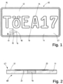
- a vehicle identification means 10 or vehicle license plate according to the invention consists of a flat license plate body 11 with a front 47 and a back 48, the license plate body 11 having a protective cover 12 ( Fig. 1 ).
- these are essentially rectangular exemplary embodiments of the vehicle identification means 10.
- almost any other geometric shape of the license plate body 11 is also possible. This depends in particular on local, regional or national regulations such as corresponding legal or other regulations.
- the vehicle identification means 10 shown in the figures has a labeling field 13 which is assigned to the front 47 of the identification means 10.
- a label 14 is provided in this label field 13, which serves for identification.
- the label 14 of the license plate 10 can be attached, for example, by printing, pasting, punching or embossing. However, it is also conceivable that the label 14 of the license plate 10 is applied using a generative process or via a 3D printing process.
- the label 14 itself is not limited to the letters and numbers shown here. Rather, it can contain any type of labeling and combination of characters or the like, including pictorial representations. However, at this point, at least the official license plate or number on a license plate is often attached to identify the vehicle.
- the vehicle identification means 10 shown here has a surrounding border 15, which is produced by embossing.
- the vehicle identification means 10 made of aluminum or sheet metal shown here it is also conceivable to produce an identification means or the license plate body 11 made of plastic or acrylic. The use of the material is usually specified by national regulations.
- the vehicle identification means 10 shown, or the license plate body 11, is assigned a rectangular opening 16.
- This opening 16 is provided as a recess or as a free space in the license plate body 11 and extends from a surface of the license plate body 11 to an underside or from the front 47 to a back 48.
- a length 17 of the rectangular opening 16 is greater than a height 18 of the opening 16.
- the length 17 is aligned parallel to a side edge of the vehicle identification means 10.
- the length 17 or the opening 16 can also have any orientation to the side edge of the vehicle identification means 10.
- An NFC transponder 19 is arranged above the opening 16 and has an antenna 20 and a data carrier 21 or chip. According to the invention, the NFC transponder 19 is positioned above the opening 16 in such a way that the antenna 20 extends at least partially over the opening 16.
- the NFC transponder 19 with the antenna 20 and the data carrier 21 is arranged on a carrier material 22.
- This carrier material 22 is electrically insulating and can be at least partially self-adhesive on one or both sides.
- This carrier material 22 together with the NFC transponder 19 is according to Fig. 2 applied to the license plate body 10 in such a way that it at least partially covers the opening 16.
- the carrier material 22 and the remaining free surface of the license plate body 11 are covered by the protective cover 12.
- This protective cover 12 can be a flexible, self-adhesive and/or retroreflective film, with preferably integrated or encapsulated microglass beads or a prismatic film and PVC film, which serve to reflect light.
- At least one layer of this protective cover 12 may contain metallic particles which have electrical conductivity.
- a further exemplary embodiment, not shown here, can provide that the NFC transponder 19 is assigned to the back 48 of the license plate body 11.
- the NFC transponder 19 is to be attached to the back 48 in the same way as previously described for the front 47. With this positioning, the NFC transponder 19 experiences increased security, since the license plate body 11 serves as a further protective shield against mechanical influences.
- the 3 and 4 show two possible exemplary embodiments of a breakthrough 16, 23 with a carrier material 22 or 24, with the carrier materials 22, 24 each being assigned an NFC transponder 19, 25 with different antenna structures 20, 26. While the antenna structure 20 of the NFC transponder 19 is rectangular is formed, the antenna structure 26 of the NFC transponder 25 describes a ring.
- the opening 16, 23 is larger than the antenna 20, 26 at least in one dimension. This is the case, for example, for the exemplary embodiment Fig. 3 It is provided that a side edge 27 of the antenna 20 or the antenna structure 20 is smaller than the height 18 of the opening 16. If this is the case, a width 28 of the antenna 20 or the antenna structure can be larger than the height 18 of the opening 16. It is important that at least one dimension of the antenna 20 is smaller than the length 17 or the height 18 of the opening 16, so that an electromagnetic field can penetrate the opening 16 or the antenna 20.
- the antenna 20, 26 of the NFC transponder 19, 25, 35, 42, in particular turns of the antenna 20, 26, a conductor loop or a coil, includes a rectangular or a round or circular surface, with a side edge 27 of this surface in Their length or a circumference of this area in its diameter is 29 at most corresponds to a length 17 of the opening 16, 23, or is smaller.
- the height 18 of the opening 16, 23 corresponds to at least 10%, in particular at least 25%, preferably at least 50% of a width 28 of the surface or the diameter 29 of the surface. Only in the case of such penetration can the in the Fig. 1 and 2 illustrated embodiment of the vehicle identification means 10 an effective coupling of the electromagnetic field to the NFC transponder 19 takes place.
- an outer diameter 29 of the antenna 26 must be smaller than at least one dimension (length/height) of the opening 23 ( Fig. 4 ). How the antenna is ultimately designed is secondary.
- the ones in the 3 and 4 Antennas 20, 26 shown are designed as coil-like conductor loops, each of which is connected to a data carrier 30, 31 and a connecting piece 32, 33.
- the data carrier 30, 31 can either also be located in the opening 16, 23 or on the license plate body 11. According to the invention, it is also conceivable that the NFC transponder 19, 25 is positioned completely in the opening 16, 23.
- the NFC transponder 19, 25 is at least partially cast in the opening 16, 23 using a casting compound. Because the NFC transponder 19, 25 is arranged with the carrier material 22, 24 both between the license plate body 11 and the protective cover 12 and is cast in the opening 16, 23, the NFC transponder 19, 25 cannot be removed from the device in a non-destructive manner Vehicle identification means 10 are removed. A simple layer structure can therefore be used to create a reliably functioning identification means with increased security against manipulation.
- a vehicle identification means 34 is structurally identical to the previously described vehicle identification means 10 with the exception that in the Fig. 5 Vehicle identification means 34 shown does not have a breakthrough 16, 23. Rather, in the exemplary embodiment shown there, an NFC transponder 35 is positioned on the front 47 of the license plate body 36, with between a carrier material 37 of the NFC transponder 35 and the License plate body 36 an electrically insulating layer 38 is arranged.
- This electrically insulating layer 38 can be designed as a double-sided adhesive plastic layer or as a lacquer layer.
- the carrier material 37 of the NFC transponder 35 on the layer 38 is covered by a protective cover 37.
- This protective cover 39 is designed in the same way as the one previously based on the exemplary embodiment Fig. 1 to 4 described.
- an antenna 40 of the NFC transponder 35 is electrically insulated from the license plate body 36 by the layer 38.
- This layer structure allows an external electromagnetic field to also couple in a very reliable manner to the antenna 40 of the NFC transponder 35 in order to both exchange data stored on a data carrier and to supply the NFC transponder, which is designed as a passive component, with sufficient electrical energy .
- the NFC transponder 35 with the carrier material 37 can be arranged at almost any position on the license plate body 36.
- the electrically insulating layer 38 is arranged only between the carrier material 37 and the license plate body 36.
- the NFC transponder 35 is assigned to the back 48 of the license plate body 36.
- the NFC transponder 35 is to be attached to the back 48 in the same way as previously described for the front 47.
- the NFC transponder 35 arranged on the back 48 of the license plate body 36 is assigned a breakthrough in the license plate body 36 in the manner described above. With this positioning, the NFC transponder 35 experiences increased security, since the license plate body 36 serves as a further protective shield against mechanical influences.
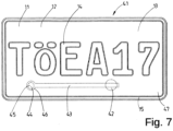
- a breakthrough for an NFC transponder 42 is designed as a slot 43. While for the NFC transponder 42 the slot 43 has the same function as before using the Fig. 1 to 4 described, the slot 43 also serves as a slot antenna for an RFID chip 44.
- the RFID chip 44 also has a data carrier 45, which is inductively coupled to the slot antenna or the slot 43 via another conductor track or coil. While the RFID chip 44 is assigned to one end of the slot 43, is located in the Fig. 7 the NFC transponder 42 at another end of the elongated, preferably rectangular, slot 43, namely on a front side 47 of the license plate body 11.
- the NFC transponder 42 is placed on the slot 43 in such a way that both a corresponding external electromagnetic field with the NFC -Transponder 42 can couple and the performance of the slot antenna or the slot 43 is not affected by the NFC transponder 42.
- the RFID chip 44 can be arranged in an expansion 46 at one end of the slot 43 or a trough and can be fixed in this expansion 46 or the trough by a casting compound.
- This casting compound can be the same compound through which the NFC transponder 42 is embedded in the slot.
- vehicle identification means 41 is designed in the same way as that in the Fig. 1 and 2 vehicle identification means 10 shown.
- both the shape and the dimension of the vehicle identification means 10, 34, 41, as well as the opening 16, 23 or the slot 43 can differ from those shown here.
- a further exemplary embodiment, not shown here, can provide that the NFC transponder 42 can be assigned to a back side 48 of the license plate body 11.
- the NFC transponder 42 is to be attached to the back 48 in the same way as previously described for the front 47.
- the NFC transponder 42 arranged on the back 48 of the license plate body 11 is assigned a breakthrough in the license plate body 11 in the manner described above. At this Positioning, the NFC transponder 42 experiences increased security since the license plate body 11 serves as a further protective shield against mechanical influences.
- a further exemplary embodiment, not shown, of the vehicle identification means 10, 34, 41 according to the invention can provide that the NFC transponder 19, 35, 42 is arranged in a trough in the license plate body 11, 36.
- the trough can be assigned to both a front 47 and a back 48.
- Reference symbol list 10 Vehicle identification means 42 NFC transponder 11 License plate body 43 slot 12 Protective cover 44 RFID chip 13 Label field 45 Disk 14 labeling 46 expansion 15 Border 47 front 16 breakthrough 48 back 17 length 18 Height 19 NFC transponder 20 antenna 21 Disk 22 Carrier material 23 breakthrough 24 Carrier material 25 NFC transponder 26 antenna 27 side edge 28 Width 29 diameter 30 Disk 31 Disk 32 connector 33 connector 34 Vehicle identification means 35 NFC transponder 36 License plate body 37 Carrier material 38 layer 39 Protective cover 40 antenna 41 Vehicle identification means
Landscapes
- Engineering & Computer Science (AREA)
- Computer Networks & Wireless Communication (AREA)
- Physics & Mathematics (AREA)
- General Physics & Mathematics (AREA)
- Microelectronics & Electronic Packaging (AREA)
- Theoretical Computer Science (AREA)
- Computer Hardware Design (AREA)
- Signal Processing (AREA)
- Mechanical Engineering (AREA)
- Details Of Aerials (AREA)
- Vehicle Waterproofing, Decoration, And Sanitation Devices (AREA)
- Near-Field Transmission Systems (AREA)
- Radar Systems Or Details Thereof (AREA)
Claims (22)
- Moyen d'identification de véhicule (10, 34, 41), en particulier plaque d'immatriculation de véhicule, comprenant un corps de plaque d'immatriculation (11, 36) qui présente au moins un champ d'inscription (13), et comprenant au moins une inscription (14) qui est associée au champ d'inscription (13) du corps de plaque d'immatriculation (11, 36), au moins un transpondeur NFC (19, 25, 35, 42) lisible sans contact pour la communication en champ proche, doté d'un support de données (21, 30, 31) et d'une antenne (20, 26), étant associé au corps de plaque d'immatriculation (11, 36), et le corps de plaque d'immatriculation (11, 36) étant recouvert d'un couvercle de protection (12, 39), caractérisé en ce que le corps de plaque d'immatriculation (11, 36) présente une perforation (16, 23) au-dessus de laquelle est disposée au moins partiellement l'antenne (20, 26) du transpondeur NFC (19, 25, 35, 42), l'antenne (20, 26) englobant une surface rectangulaire ou une surface ronde ou circulaire, et un bord latéral (27) de ladite surface dans sa longueur ou un périmètre de ladite surface dans son diamètre (29) correspondant au maximum à une longueur (17) de la perforation (16, 23), l'antenne (20, 26) étant disposée à une position quelconque de la perforation (16, 23), au moins deux zones partielles opposées de l'antenne (20, 26) étant disposées au-dessus de la perforation (16, 23) et au moins deux autres zones partielles opposées de l'antenne (20, 26) étant disposées à l'extérieur de la perforation (16, 23).
- Moyen d'identification de véhicule (10, 34, 41) selon la revendication 1, caractérisé en ce que le support de données (21, 30, 31) et/ou au moins des sections de l'antenne (20, 26) du transpondeur NFC (19, 25, 35, 42) sont coulés dans la perforation (16, 23) dans une masse de scellement non électroconductrice, notamment une matière plastique ou une résine, notamment en ce que la perforation (16, 23) est remplie de la masse de scellement.
- Moyen d'identification de véhicule (10, 34, 41) selon la revendication 1 ou 2, caractérisé en ce que des spires de l'antenne (20, 26), une boucle conductrice ou une bobine englobent une surface rectangulaire ou une surface ronde ou circulaire, et en ce qu'un bord latéral (27) de ladite surface dans sa longueur ou un périmètre de ladite surface dans son diamètre (29) correspond au plus et est de préférence inférieure à une longueur (17) de la perforation, et en ce qu'une hauteur (18) de la perforation (16, 23) correspond à au moins 10 %, notamment à au moins 25 %, de préférence à au moins 50 % d'une largeur (28) de la surface ou du diamètre (29) de la surface.
- Moyen d'identification de véhicule (10, 34, 41) selon l'une des revendications précédentes, caractérisé en ce que le transpondeur NFC (19, 25, 35, 42), doté de l'antenne (20, 26) et du support de données (21, 30, 31), est disposé sur un matériau de support, de préférence autocollant (22, 24, 37), directement sur une face avant (47) du corps de plaque d'immatriculation (11, 36) et au moins partiellement au-dessus de la perforation (16, 23), et en ce que le couvercle de protection (12, 39) est appliqué sur le corps de plaque d'immatriculation (11, 36) au-dessus du transpondeur NFC (19, 25, 35, 42).
- Moyen d'identification de véhicule (10, 34, 41) selon l'une des revendications précédentes, caractérisé en ce que le transpondeur NFC (19, 25, 35, 42), doté de l'antenne (20, 26) et du support de données (21, 30, 31) est disposé sur un matériau de support (22, 24, 37), de préférence autocollant, directement sur une face arrière (48) du corps de plaque d'immatriculation (11, 36) et au moins partiellement au-dessus de la perforation (16, 23).
- Moyen d'identification de véhicule (10, 34, 41) selon la revendication 1, caractérisé en ce que le transpondeur NFC (19, 25, 35, 42), doté de l'antenne (20, 26) et du support de données (21, 30, 31), sur un matériau de support (22, 24, 37) sont associés au corps de plaque d'immatriculation (11, 36).
- Moyen d'identification de véhicule (10, 34, 41) selon la revendication 6, caractérisé en ce que le transpondeur NFC (19, 25, 35, 42) est fixé directement, ou sur le couvercle de protection (12, 39), à une face avant (47), de préférence dans un creux, du corps de plaque d'immatriculation (11, 36), et en ce que le couvercle de protection (12, 39) ou un film de protection est appliqué sur le corps de plaque d'immatriculation (11, 36) au-dessus du transpondeur NFC (19, 25, 35, 42), le transpondeur NFC (19, 25, 35, 42) étant notamment coulé dans le creux (Z) avec une masse de scellement.
- Moyen d'identification de véhicule (10, 34, 41) selon la revendication 6, caractérisé en ce que le transpondeur NFC (19, 25, 35, 42) est fixé directement à une face arrière (48), de préférence dans un creux, du corps de plaque d'immatriculation (11, 36), le transpondeur NFC (19, 25, 35, 42) étant notamment coulé dans le creux avec une masse de scellement.
- Moyen d'identification de véhicule (10, 34, 41) selon l'une des revendications 6 à 8, caractérisé en ce qu'une couche électriquement isolante (38), de préférence une matière plastique ou une couche de vernis, est disposée entre le matériau de support (22, 24, 37), de préférence autocollant, du transpondeur NFC (19, 25, 35, 42) et le corps de plaque d'immatriculation (11, 36).
- Moyen d'identification de véhicule (10, 34, 41) selon l'une des revendications 6 à 9, caractérisé en ce que le transpondeur NFC (19, 25, 35, 42) est disposé dans un boîtier non électroconducteur, et en ce que le boîtier est positionné directement sur le corps de plaque d'immatriculation (11, 36).
- Moyen d'identification de véhicule (10, 34, 41) selon l'une des revendications 1 à 10, caractérisé en ce que le corps de plaque d'immatriculation (11, 36) comporte une antenne UHF formée par une fente (43), et en ce qu'un support de données (45) générant un champ magnétique est associé à ladite antenne UHF, l'antenne (20, 26) du transpondeur NFC (19, 25, 35, 42) étant associée au moins partiellement à la fente (43), ou le transpondeur NFC (19, 25, 35, 42), doté de l'antenne (20, 26) et du support de données (21, 30, 31), sur un matériau de support (22, 24, 37), étant associé au corps de plaque d'immatriculation (11, 36).
- Moyen d'identification de véhicule (10, 34, 41) selon la revendication 11, caractérisé en ce que le transpondeur NFC (19, 25, 35, 42), notamment doté de l'antenne (20, 26) et du support de données (21, 30, 31), est disposé dans un creux ménagé dans le corps de plaque d'immatriculation (11, 36).
- Moyen d'identification de véhicule (10, 34, 41) selon l'une des revendications précédentes, caractérisé en ce que l'antenne (20, 26) du transpondeur NFC (19, 25, 35, 42) est disposée au moins partiellement, de préférence entièrement, dans ou au-dessus de la fente (43) ou d'une perforation (16, 23), notamment sur une face avant (47) ou une face arrière (48) du corps de plaque d'immatriculation (11, 36).
- Moyen d'identification de véhicule (10, 34, 41) selon l'une des revendications 11 à 13, caractérisé en ce que le support de données (45) est couplé par induction à la fente (43), le support de données (45) comportant une puce, au moins une bobine reliée à celle-ci de manière électroconductrice et un support constitué d'un matériau isolant ou non conducteur, et la puce étant notamment conçue sous la forme d'une puce d'identification par radiofréquence (44) (puce RFID) passive.
- Moyen d'identification de véhicule (10, 34, 41) selon l'une des revendications 11 à 14, caractérisé en ce que le support de données (45) est disposé de manière électriquement isolée dans la zone d'une extrémité de la fente (43), et en ce que le transpondeur NFC (19, 25, 35, 42) est associé à une zone d'extrémité opposée de la fente (43), la fente (43) étant de préférence prolongée de la longueur sur laquelle le transpondeur NFC (19, 25, 35, 42) recouvre la fente (43).
- Moyen d'identification de véhicule (10, 34, 41) selon l'une des revendications 11 à 15, caractérisé en ce que le support de données (45) est disposé de manière isolée à l'intérieur de la fente (43) ou au-dessus de la fente (43), et de préférence en ce que des composants électriquement conducteurs du support de données (45) sont espacés des surfaces de délimitation de la fente (43) .
- Moyen d'identification de véhicule (10, 34, 41) selon l'une des revendications 11 à 16, caractérisé en ce que le support de données (45) est encastré dans le corps de plaque d'immatriculation (11, 36), et est notamment fixé dans la fente (43), de préférence par au moins un revêtement sur le corps de plaque d'immatriculation (11, 36).
- Moyen d'identification de véhicule (10, 34, 41) selon l'une des revendications précédentes, caractérisé en ce qu'au moins un revêtement visible est réalisé sous la forme d'un film réfléchissant, notamment autocollant, qui est réalisé de préférence dans la zone du support de données (45) et/ou de la fente (43) et/ou du transpondeur NFC (19, 25, 35, 42), de telle sorte qu'il ne comporte aucun composant électroconducteur, et notamment que le revêtement présente une résistance ohmique très élevée.
- Moyen d'identification de véhicule (10, 34, 41) selon l'une des revendications 11 à 18, caractérisé en ce que le support de données (45) est disposé dans un creux de réception ménagé dans le corps de plaque d'immatriculation, le creux de réception étant de préférence associé à une extrémité de la fente et présentant de préférence une paroi de fond dans laquelle s'étend une extrémité de la fente (43), ou la paroi de fond présentant une ouverture qui est plus petite que le support de données (45).
- Moyen d'identification de véhicule (10, 34, 41) selon la revendication 14, caractérisé en ce que la puce RFID et le transpondeur NFC forment une unité structurelle avec deux antennes destinées aux plages de fréquences HF et UHF, lesquelles peuvent être lues indépendamment l'une de l'autre.
- Moyen d'identification de véhicule (10, 34, 41) selon l'une des revendications précédentes, caractérisé en ce que le couvercle de protection (12, 39) est réalisé sous la forme d'un film flexible, autocollant et rétroréfléchissant, de préférence avec des microbilles de verre noyées ou encapsulées ou sous la forme d'un film prismatique, au moins une couche du film contenant de préférence des particules métalliques qui possèdent une conductivité électrique, ou en ce que le couvercle de protection est constitué d'un matériau électroconducteur, notamment constitué d'aluminium ou de tôle, ou d'un matériau non électroconducteur, notamment de matière plastique ou acrylique.
- Moyen d'identification de véhicule (10, 34, 41) selon l'une des revendications précédentes, caractérisé en ce que le corps de plaque d'immatriculation (11, 36) est constitué d'un matériau électroconducteur, notamment d'aluminium ou de tôle, ou d'un matériau non électroconducteur, notamment de matière plastique ou acrylique, ou en ce que le corps de plaque d'immatriculation est réalisé sous la forme d'un film flexible, autocollant et rétroréfléchissant, de préférence avec des microbilles de verre noyées ou encapsulées ou sous la forme d'un film prismatique, des particules métalliques qui possèdent une conductivité électrique étant de préférence contenues dans au moins une couche du film.
Priority Applications (3)
| Application Number | Priority Date | Filing Date | Title |
|---|---|---|---|
| RS20240471A RS65444B1 (sr) | 2018-03-28 | 2019-03-26 | Sredstvo za identifikaciju vozila |
| HRP20240577TT HRP20240577T1 (hr) | 2018-03-28 | 2019-03-26 | Sredstvo za identifikaciju vozila |
| EP23214221.6A EP4306366A3 (fr) | 2018-03-28 | 2019-03-26 | Moyen d'identification de véhicule |
Applications Claiming Priority (2)
| Application Number | Priority Date | Filing Date | Title |
|---|---|---|---|
| DE102018002585.4A DE102018002585A1 (de) | 2018-03-28 | 2018-03-28 | Fahrzeugidentifikationsmittel |
| PCT/EP2019/000094 WO2019185192A1 (fr) | 2018-03-28 | 2019-03-26 | Moyen d'identification de véhicule |
Related Child Applications (2)
| Application Number | Title | Priority Date | Filing Date |
|---|---|---|---|
| EP23214221.6A Division-Into EP4306366A3 (fr) | 2018-03-28 | 2019-03-26 | Moyen d'identification de véhicule |
| EP23214221.6A Division EP4306366A3 (fr) | 2018-03-28 | 2019-03-26 | Moyen d'identification de véhicule |
Publications (3)
| Publication Number | Publication Date |
|---|---|
| EP3776359A1 EP3776359A1 (fr) | 2021-02-17 |
| EP3776359B1 true EP3776359B1 (fr) | 2024-03-06 |
| EP3776359C0 EP3776359C0 (fr) | 2024-03-06 |
Family
ID=66223654
Family Applications (2)
| Application Number | Title | Priority Date | Filing Date |
|---|---|---|---|
| EP23214221.6A Pending EP4306366A3 (fr) | 2018-03-28 | 2019-03-26 | Moyen d'identification de véhicule |
| EP19718246.2A Active EP3776359B1 (fr) | 2018-03-28 | 2019-03-26 | Moyen d'identification de véhicule |
Family Applications Before (1)
| Application Number | Title | Priority Date | Filing Date |
|---|---|---|---|
| EP23214221.6A Pending EP4306366A3 (fr) | 2018-03-28 | 2019-03-26 | Moyen d'identification de véhicule |
Country Status (21)
| Country | Link |
|---|---|
| US (1) | US11935333B2 (fr) |
| EP (2) | EP4306366A3 (fr) |
| JP (1) | JP7132348B2 (fr) |
| CN (1) | CN112154457B (fr) |
| AR (1) | AR114700A1 (fr) |
| AU (1) | AU2019245602B2 (fr) |
| BR (1) | BR112020018694A2 (fr) |
| CA (1) | CA3094893A1 (fr) |
| CL (1) | CL2020002370A1 (fr) |
| DE (1) | DE102018002585A1 (fr) |
| ES (1) | ES2980157T3 (fr) |
| HR (1) | HRP20240577T1 (fr) |
| HU (1) | HUE066010T2 (fr) |
| MA (1) | MA52196A (fr) |
| MX (1) | MX2020010019A (fr) |
| NZ (1) | NZ768225A (fr) |
| PL (1) | PL3776359T3 (fr) |
| RS (1) | RS65444B1 (fr) |
| TW (1) | TWI709498B (fr) |
| WO (1) | WO2019185192A1 (fr) |
| ZA (1) | ZA202005938B (fr) |
Families Citing this family (7)
| Publication number | Priority date | Publication date | Assignee | Title |
|---|---|---|---|---|
| DE102018007679A1 (de) * | 2018-09-28 | 2020-04-02 | Tönnjes Isi Patent Holding Gmbh | Kennzeichen für ein Fahrzeug |
| DE102019121368A1 (de) * | 2019-08-07 | 2021-02-11 | Schreiner Group Gmbh & Co. Kg | Kennzeichnungsetikett, Kennzeichnungssystem und Verfahren zum Herstellen eines Kennzeichnungsetiketts |
| WO2021134059A1 (fr) * | 2019-12-28 | 2021-07-01 | Avery Dennison Retail Information Services, Llc | Dispositifs rfid bi-mode |
| DE102021113260A1 (de) * | 2021-05-21 | 2022-11-24 | Tönnjes Isi Patent Holding Gmbh | Manipulationssicherer elektronischer Chip, Kennzeichen für ein Fahrzeug und Verfahren zur Herstellung eines manipulationssicheren elektronischen Chips |
| DE102021115478A1 (de) | 2021-06-15 | 2022-12-15 | Mustafa Burma | Fahrzeug mit einer Kennzeichen-Anordnung, Verfahren zum Betrieb eines solchen Fahrzeuges sowie eine Kennzeichen-Anordnung |
| JP7412810B1 (ja) | 2022-04-28 | 2024-01-15 | 立山科学株式会社 | Rfタグ |
| EP4269125A1 (fr) * | 2022-04-28 | 2023-11-01 | Tönnjes ISI Patent Holding GmbH | Procédé et dispositif pour estamper des plaques d'immatriculation de véhicules |
Family Cites Families (28)
| Publication number | Priority date | Publication date | Assignee | Title |
|---|---|---|---|---|
| US7158031B2 (en) * | 1992-08-12 | 2007-01-02 | Micron Technology, Inc. | Thin, flexible, RFID label and system for use |
| DE59808386D1 (de) * | 1997-10-14 | 2003-06-18 | Siemens Ag | Fahrzeugkennzeichen mit berührungslos lesbarem elektronischen datenträger und herstellungsverfahren |
| US6025784A (en) * | 1998-02-12 | 2000-02-15 | Micron Technology, Inc. | Vehicles, license plate frame assemblies, methods of forming license plate frames, and methods of attaching RFIDs, transponders and modulators to vehicles |
| USD510103S1 (en) * | 2004-06-03 | 2005-09-27 | American Express Travel Related Services Company, Inc. | Transparent card with an antenna |
| USD512095S1 (en) * | 2004-06-03 | 2005-11-29 | American Express Travel Related Services Company, Inc. | Card with an antenna and a blue rectangle |
| KR100676144B1 (ko) * | 2004-12-24 | 2007-01-31 | 샬롬엔지니어링 주식회사 | 전자태그 기능을 가지는 차량 번호판 |
| DE202005018589U1 (de) * | 2005-11-29 | 2007-04-12 | Zissel Hardy | Kennzeichnungsblech für Kraftfahrzeuge mit Antenne |
| US7463150B2 (en) * | 2005-10-28 | 2008-12-09 | 3M Innovative Properties Company | Vehicle identification tag and methods of verifying the validity of a vehicle identification tag |
| US8002173B2 (en) * | 2006-07-11 | 2011-08-23 | Intermec Ip Corp. | Automatic data collection device, method and article |
| NZ549173A (en) * | 2006-08-15 | 2007-06-29 | Times 7 Holdings Ltd | Licence plate with integrated antenna |
| NL1032542C2 (nl) * | 2006-09-20 | 2008-03-21 | Knieriem B V J | Voertuigidentificatie. |
| MX2009006781A (es) * | 2006-12-21 | 2010-01-15 | Neology Inc | Sistemas y métodos para una placa de metal habilitada con identificación por radio frecuencia. |
| DE102009033559A1 (de) * | 2008-11-04 | 2010-05-06 | J.H. Tönnjes E.A.S.T. GmbH & Co. KG | Kennzeichen für ein Fahrzeug |
| US8393547B2 (en) * | 2009-08-05 | 2013-03-12 | Perfect Plastic Printing Corporation | RF proximity financial transaction card having metallic foil layer(s) |
| EP2572321A2 (fr) * | 2010-05-17 | 2013-03-27 | ZIH Corporation | Identification par radiofréquence par transpondeur double |
| US9812782B2 (en) * | 2011-08-08 | 2017-11-07 | Féinics Amatech Teoranta | Coupling frames for RFID devices |
| SI23960A (sl) * | 2011-12-10 | 2013-06-28 | Janko Cerar | Metoda daljinske kontrole skladnosti registracije vozila z identifikacijo vozila |
| DE102012106594A1 (de) * | 2012-07-20 | 2014-01-23 | J.H. Tönnjes E.A.S.T. GmbH & Co. KG | Fahrzeugidentifikationsmittel |
| RU2514025C1 (ru) * | 2012-11-16 | 2014-04-27 | Игорь Юрьевич Мацур | Индукционная система обнаружения и идентификации транспортных средств, индукционный регистрационный номерной знак и индукционный считыватель |
| KR20140101522A (ko) * | 2013-02-12 | 2014-08-20 | 김준규 | 주차위치 확인 단말기 |
| DE102014012291A1 (de) | 2014-08-22 | 2016-02-25 | Tönnjes Isi Patent Holding Gmbh | Kennzeichen für ein Fahrzeug |
| EP3076341B1 (fr) * | 2015-04-02 | 2018-01-10 | EM Microelectronic-Marin SA | Dispositif d'identification hf-uhf à double fréquence, en particulier de type passif |
| CN106997536A (zh) * | 2016-01-25 | 2017-08-01 | 黄圣傑 | 具有rfid/nfc功能的纸质、基板载具及其防伪辨识方法 |
| JP2018011111A (ja) | 2016-07-11 | 2018-01-18 | デクセリアルズ株式会社 | アンテナ装置 |
| EP3340114B1 (fr) * | 2016-12-22 | 2020-09-30 | EM Microelectronic-Marin SA | Circuit rfid a deux frequences de communication muni d'une boucle d'inviolabilite |
| US9875439B2 (en) * | 2017-06-27 | 2018-01-23 | Rfid Integrated Marketing Co., Ltd. | License plate radio electronic identifier |
| DE102018007679A1 (de) * | 2018-09-28 | 2020-04-02 | Tönnjes Isi Patent Holding Gmbh | Kennzeichen für ein Fahrzeug |
| USD898646S1 (en) * | 2020-02-21 | 2020-10-13 | Randy Vincent | Plate frame |
-
2018
- 2018-03-28 DE DE102018002585.4A patent/DE102018002585A1/de active Pending
-
2019
- 2019-03-15 AR ARP190100658A patent/AR114700A1/es active IP Right Grant
- 2019-03-19 TW TW108109366A patent/TWI709498B/zh active
- 2019-03-26 EP EP23214221.6A patent/EP4306366A3/fr active Pending
- 2019-03-26 ES ES19718246T patent/ES2980157T3/es active Active
- 2019-03-26 US US16/982,216 patent/US11935333B2/en active Active
- 2019-03-26 NZ NZ768225A patent/NZ768225A/en unknown
- 2019-03-26 PL PL19718246.2T patent/PL3776359T3/pl unknown
- 2019-03-26 MX MX2020010019A patent/MX2020010019A/es unknown
- 2019-03-26 BR BR112020018694-5A patent/BR112020018694A2/pt unknown
- 2019-03-26 MA MA052196A patent/MA52196A/fr unknown
- 2019-03-26 WO PCT/EP2019/000094 patent/WO2019185192A1/fr active Application Filing
- 2019-03-26 CA CA3094893A patent/CA3094893A1/fr active Pending
- 2019-03-26 HR HRP20240577TT patent/HRP20240577T1/hr unknown
- 2019-03-26 JP JP2020551261A patent/JP7132348B2/ja active Active
- 2019-03-26 EP EP19718246.2A patent/EP3776359B1/fr active Active
- 2019-03-26 HU HUE19718246A patent/HUE066010T2/hu unknown
- 2019-03-26 RS RS20240471A patent/RS65444B1/sr unknown
- 2019-03-26 AU AU2019245602A patent/AU2019245602B2/en active Active
- 2019-03-26 CN CN201980021365.3A patent/CN112154457B/zh active Active
-
2020
- 2020-09-14 CL CL2020002370A patent/CL2020002370A1/es unknown
- 2020-09-25 ZA ZA2020/05938A patent/ZA202005938B/en unknown
Also Published As
| Publication number | Publication date |
|---|---|
| NZ768225A (en) | 2023-03-31 |
| RS65444B1 (sr) | 2024-05-31 |
| JP2021517407A (ja) | 2021-07-15 |
| MA52196A (fr) | 2021-02-17 |
| TW201941989A (zh) | 2019-11-01 |
| CL2020002370A1 (es) | 2021-03-12 |
| EP4306366A2 (fr) | 2024-01-17 |
| WO2019185192A1 (fr) | 2019-10-03 |
| HRP20240577T1 (hr) | 2024-07-19 |
| EP4306366A3 (fr) | 2024-04-17 |
| ES2980157T3 (es) | 2024-09-30 |
| AU2019245602B2 (en) | 2022-12-08 |
| ZA202005938B (en) | 2022-03-30 |
| TWI709498B (zh) | 2020-11-11 |
| JP7132348B2 (ja) | 2022-09-06 |
| CN112154457B (zh) | 2024-07-05 |
| CN112154457A (zh) | 2020-12-29 |
| US11935333B2 (en) | 2024-03-19 |
| RU2020134525A (ru) | 2022-04-28 |
| BR112020018694A2 (pt) | 2021-01-12 |
| EP3776359C0 (fr) | 2024-03-06 |
| AU2019245602A1 (en) | 2020-11-12 |
| DE102018002585A1 (de) | 2019-10-02 |
| MX2020010019A (es) | 2020-10-14 |
| AR114700A1 (es) | 2020-10-07 |
| PL3776359T3 (pl) | 2024-07-08 |
| RU2020134525A3 (fr) | 2022-04-28 |
| US20210027553A1 (en) | 2021-01-28 |
| CA3094893A1 (fr) | 2019-10-03 |
| HUE066010T2 (hu) | 2024-07-28 |
| EP3776359A1 (fr) | 2021-02-17 |
Similar Documents
| Publication | Publication Date | Title |
|---|---|---|
| EP3776359B1 (fr) | Moyen d'identification de véhicule | |
| EP2344364B1 (fr) | Plaques minéralogiques pour véhicules | |
| EP2875472B1 (fr) | Moyen d'identification de véhicule | |
| DE102017130940B4 (de) | Chipkartenkörper, Chipkarte und Verfahren zum Herstellen eines Chipkartenkörpers | |
| EP1886263B1 (fr) | Systeme comportant un transpondeur et un element metallique | |
| EP1939793B1 (fr) | Petite plaquette de détection passive RF | |
| WO2016026543A1 (fr) | Plaque d'immatriculation pour véhicule | |
| EP1435067B8 (fr) | Dispositif pour blinder un transpondeur, procede pour produire un blindage correspondant et transpondeur equipe de ce blindage | |
| DE202019001169U1 (de) | Kennzeichen für ein Fahrzeug | |
| EP2168081B1 (fr) | Dispositif, procédé et utilisation permettant le blindage d'un transpondeur rfid contre les champs magnétiques | |
| DE102007037293A1 (de) | Vorrichtung, Verfahren und Verwendung zur Magnetfeldabschirmung eines RFID-Transponders | |
| EP3956179B1 (fr) | Plaque d'immatriculation pour un véhicule et procédé de fabrication d'une plaque d'immatriculation pour un véhicule | |
| EP3820742B1 (fr) | Plaque d'immatriculation pour véhicule et procédé de production d'une plaque d'immatriculation pour véhicule | |
| EP3769261B1 (fr) | Agencement d'une plaque et d'un support de plaque portant la plaque | |
| DE102018106401B4 (de) | NFC-Metallemblem | |
| EP3132388B1 (fr) | Appareil pour la prévention d'un vol de données, fraude d'identité et de payement lors d'une transmission sans contact de données par ondes électromagnétiques | |
| DE102021005830A1 (de) | Kartenförmiger Datenträger und Verfahren zum Herstellen eines kartenförmigen Datenträgers | |
| DE102011087928B4 (de) | Metallischer trägerkörper mit transponder | |
| DE102006051902A1 (de) | Transponderanordnung und Verfahren zum Betrieb von Transpondern | |
| DE102017001798A1 (de) | Sicherungselement für Schilder | |
| DE202013100057U1 (de) | RFID-Transponder |
Legal Events
| Date | Code | Title | Description |
|---|---|---|---|
| REG | Reference to a national code |
Ref country code: HR Ref legal event code: TUEP Ref document number: P20240577T Country of ref document: HR |
|
| STAA | Information on the status of an ep patent application or granted ep patent |
Free format text: STATUS: UNKNOWN |
|
| STAA | Information on the status of an ep patent application or granted ep patent |
Free format text: STATUS: THE INTERNATIONAL PUBLICATION HAS BEEN MADE |
|
| PUAI | Public reference made under article 153(3) epc to a published international application that has entered the european phase |
Free format text: ORIGINAL CODE: 0009012 |
|
| STAA | Information on the status of an ep patent application or granted ep patent |
Free format text: STATUS: REQUEST FOR EXAMINATION WAS MADE |
|
| 17P | Request for examination filed |
Effective date: 20200930 |
|
| AK | Designated contracting states |
Kind code of ref document: A1 Designated state(s): AL AT BE BG CH CY CZ DE DK EE ES FI FR GB GR HR HU IE IS IT LI LT LU LV MC MK MT NL NO PL PT RO RS SE SI SK SM TR |
|
| AX | Request for extension of the european patent |
Extension state: BA ME |
|
| STAA | Information on the status of an ep patent application or granted ep patent |
Free format text: STATUS: EXAMINATION IS IN PROGRESS |
|
| 17Q | First examination report despatched |
Effective date: 20220207 |
|
| GRAP | Despatch of communication of intention to grant a patent |
Free format text: ORIGINAL CODE: EPIDOSNIGR1 |
|
| STAA | Information on the status of an ep patent application or granted ep patent |
Free format text: STATUS: GRANT OF PATENT IS INTENDED |
|
| INTG | Intention to grant announced |
Effective date: 20230928 |
|
| GRAS | Grant fee paid |
Free format text: ORIGINAL CODE: EPIDOSNIGR3 |
|
| GRAA | (expected) grant |
Free format text: ORIGINAL CODE: 0009210 |
|
| STAA | Information on the status of an ep patent application or granted ep patent |
Free format text: STATUS: THE PATENT HAS BEEN GRANTED |
|
| AK | Designated contracting states |
Kind code of ref document: B1 Designated state(s): AL AT BE BG CH CY CZ DE DK EE ES FI FR GB GR HR HU IE IS IT LI LT LU LV MC MK MT NL NO PL PT RO RS SE SI SK SM TR |
|
| REG | Reference to a national code |
Ref country code: CH Ref legal event code: EP |
|
| REG | Reference to a national code |
Ref country code: DE Ref legal event code: R096 Ref document number: 502019010741 Country of ref document: DE |
|
| REG | Reference to a national code |
Ref country code: IE Ref legal event code: FG4D Free format text: LANGUAGE OF EP DOCUMENT: GERMAN |
|
| PGFP | Annual fee paid to national office [announced via postgrant information from national office to epo] |
Ref country code: IE Payment date: 20240326 Year of fee payment: 6 |
|
| U01 | Request for unitary effect filed |
Effective date: 20240319 |
|
| U07 | Unitary effect registered |
Designated state(s): AT BE BG DE DK EE FI FR IT LT LU LV MT NL PT SE SI Effective date: 20240326 |
|
| PGFP | Annual fee paid to national office [announced via postgrant information from national office to epo] |
Ref country code: GB Payment date: 20240322 Year of fee payment: 6 |
|
| U20 | Renewal fee paid [unitary effect] |
Year of fee payment: 6 Effective date: 20240327 |
|
| REG | Reference to a national code |
Ref country code: SK Ref legal event code: T3 Ref document number: E 43954 Country of ref document: SK |
|
| REG | Reference to a national code |
Ref country code: HR Ref legal event code: ODRP Ref document number: P20240577T Country of ref document: HR Payment date: 20240503 Year of fee payment: 6 |
|
| PGFP | Annual fee paid to national office [announced via postgrant information from national office to epo] |
Ref country code: GR Payment date: 20240607 Year of fee payment: 6 |
|
| PGFP | Annual fee paid to national office [announced via postgrant information from national office to epo] |
Ref country code: CH Payment date: 20240401 Year of fee payment: 6 Ref country code: HR Payment date: 20240503 Year of fee payment: 6 Ref country code: RS Payment date: 20240325 Year of fee payment: 6 |
|
| REG | Reference to a national code |
Ref country code: HR Ref legal event code: T1PR Ref document number: P20240577 Country of ref document: HR |
|
| PGFP | Annual fee paid to national office [announced via postgrant information from national office to epo] |
Ref country code: ES Payment date: 20240403 Year of fee payment: 6 |
|
| PGFP | Annual fee paid to national office [announced via postgrant information from national office to epo] |
Ref country code: CZ Payment date: 20240327 Year of fee payment: 6 |
|
| REG | Reference to a national code |
Ref country code: GR Ref legal event code: EP Ref document number: 20240401276 Country of ref document: GR Effective date: 20240716 |
|
| REG | Reference to a national code |
Ref country code: HU Ref legal event code: AG4A Ref document number: E066010 Country of ref document: HU |
|
| PGFP | Annual fee paid to national office [announced via postgrant information from national office to epo] |
Ref country code: SK Payment date: 20240326 Year of fee payment: 6 |
|
| PGFP | Annual fee paid to national office [announced via postgrant information from national office to epo] |
Ref country code: RO Payment date: 20240530 Year of fee payment: 6 Ref country code: NO Payment date: 20240424 Year of fee payment: 6 |
|
| PGFP | Annual fee paid to national office [announced via postgrant information from national office to epo] |
Ref country code: PL Payment date: 20240325 Year of fee payment: 6 |
|
| PGFP | Annual fee paid to national office [announced via postgrant information from national office to epo] |
Ref country code: TR Payment date: 20240530 Year of fee payment: 6 Ref country code: HU Payment date: 20240328 Year of fee payment: 6 |
|
| REG | Reference to a national code |
Ref country code: ES Ref legal event code: FG2A Ref document number: 2980157 Country of ref document: ES Kind code of ref document: T3 Effective date: 20240930 |