EP3770541B1 - Wick manufacturing method - Google Patents
Wick manufacturing method Download PDFInfo
- Publication number
- EP3770541B1 EP3770541B1 EP19770441.4A EP19770441A EP3770541B1 EP 3770541 B1 EP3770541 B1 EP 3770541B1 EP 19770441 A EP19770441 A EP 19770441A EP 3770541 B1 EP3770541 B1 EP 3770541B1
- Authority
- EP
- European Patent Office
- Prior art keywords
- wick
- sintered compact
- material powder
- manufacturing
- powder
- Prior art date
- Legal status (The legal status is an assumption and is not a legal conclusion. Google has not performed a legal analysis and makes no representation as to the accuracy of the status listed.)
- Active
Links
Images


Classifications
-
- B—PERFORMING OPERATIONS; TRANSPORTING
- B22—CASTING; POWDER METALLURGY
- B22F—WORKING METALLIC POWDER; MANUFACTURE OF ARTICLES FROM METALLIC POWDER; MAKING METALLIC POWDER; APPARATUS OR DEVICES SPECIALLY ADAPTED FOR METALLIC POWDER
- B22F7/00—Manufacture of composite layers, workpieces, or articles, comprising metallic powder, by sintering the powder, with or without compacting wherein at least one part is obtained by sintering or compression
- B22F7/06—Manufacture of composite layers, workpieces, or articles, comprising metallic powder, by sintering the powder, with or without compacting wherein at least one part is obtained by sintering or compression of composite workpieces or articles from parts, e.g. to form tipped tools
- B22F7/08—Manufacture of composite layers, workpieces, or articles, comprising metallic powder, by sintering the powder, with or without compacting wherein at least one part is obtained by sintering or compression of composite workpieces or articles from parts, e.g. to form tipped tools with one or more parts not made from powder
-
- F—MECHANICAL ENGINEERING; LIGHTING; HEATING; WEAPONS; BLASTING
- F28—HEAT EXCHANGE IN GENERAL
- F28D—HEAT-EXCHANGE APPARATUS, NOT PROVIDED FOR IN ANOTHER SUBCLASS, IN WHICH THE HEAT-EXCHANGE MEDIA DO NOT COME INTO DIRECT CONTACT
- F28D15/00—Heat-exchange apparatus with the intermediate heat-transfer medium in closed tubes passing into or through the conduit walls ; Heat-exchange apparatus employing intermediate heat-transfer medium or bodies
- F28D15/02—Heat-exchange apparatus with the intermediate heat-transfer medium in closed tubes passing into or through the conduit walls ; Heat-exchange apparatus employing intermediate heat-transfer medium or bodies in which the medium condenses and evaporates, e.g. heat pipes
- F28D15/04—Heat-exchange apparatus with the intermediate heat-transfer medium in closed tubes passing into or through the conduit walls ; Heat-exchange apparatus employing intermediate heat-transfer medium or bodies in which the medium condenses and evaporates, e.g. heat pipes with tubes having a capillary structure
- F28D15/046—Heat-exchange apparatus with the intermediate heat-transfer medium in closed tubes passing into or through the conduit walls ; Heat-exchange apparatus employing intermediate heat-transfer medium or bodies in which the medium condenses and evaporates, e.g. heat pipes with tubes having a capillary structure characterised by the material or the construction of the capillary structure
-
- B—PERFORMING OPERATIONS; TRANSPORTING
- B22—CASTING; POWDER METALLURGY
- B22F—WORKING METALLIC POWDER; MANUFACTURE OF ARTICLES FROM METALLIC POWDER; MAKING METALLIC POWDER; APPARATUS OR DEVICES SPECIALLY ADAPTED FOR METALLIC POWDER
- B22F3/00—Manufacture of workpieces or articles from metallic powder characterised by the manner of compacting or sintering; Apparatus specially adapted therefor ; Presses and furnaces
- B22F3/10—Sintering only
- B22F3/11—Making porous workpieces or articles
- B22F3/1103—Making porous workpieces or articles with particular physical characteristics
-
- B—PERFORMING OPERATIONS; TRANSPORTING
- B22—CASTING; POWDER METALLURGY
- B22F—WORKING METALLIC POWDER; MANUFACTURE OF ARTICLES FROM METALLIC POWDER; MAKING METALLIC POWDER; APPARATUS OR DEVICES SPECIALLY ADAPTED FOR METALLIC POWDER
- B22F3/00—Manufacture of workpieces or articles from metallic powder characterised by the manner of compacting or sintering; Apparatus specially adapted therefor ; Presses and furnaces
- B22F3/18—Manufacture of workpieces or articles from metallic powder characterised by the manner of compacting or sintering; Apparatus specially adapted therefor ; Presses and furnaces by using pressure rollers
-
- B—PERFORMING OPERATIONS; TRANSPORTING
- B22—CASTING; POWDER METALLURGY
- B22F—WORKING METALLIC POWDER; MANUFACTURE OF ARTICLES FROM METALLIC POWDER; MAKING METALLIC POWDER; APPARATUS OR DEVICES SPECIALLY ADAPTED FOR METALLIC POWDER
- B22F7/00—Manufacture of composite layers, workpieces, or articles, comprising metallic powder, by sintering the powder, with or without compacting wherein at least one part is obtained by sintering or compression
- B22F7/06—Manufacture of composite layers, workpieces, or articles, comprising metallic powder, by sintering the powder, with or without compacting wherein at least one part is obtained by sintering or compression of composite workpieces or articles from parts, e.g. to form tipped tools
- B22F7/062—Manufacture of composite layers, workpieces, or articles, comprising metallic powder, by sintering the powder, with or without compacting wherein at least one part is obtained by sintering or compression of composite workpieces or articles from parts, e.g. to form tipped tools involving the connection or repairing of preformed parts
-
- F—MECHANICAL ENGINEERING; LIGHTING; HEATING; WEAPONS; BLASTING
- F28—HEAT EXCHANGE IN GENERAL
- F28D—HEAT-EXCHANGE APPARATUS, NOT PROVIDED FOR IN ANOTHER SUBCLASS, IN WHICH THE HEAT-EXCHANGE MEDIA DO NOT COME INTO DIRECT CONTACT
- F28D15/00—Heat-exchange apparatus with the intermediate heat-transfer medium in closed tubes passing into or through the conduit walls ; Heat-exchange apparatus employing intermediate heat-transfer medium or bodies
- F28D15/02—Heat-exchange apparatus with the intermediate heat-transfer medium in closed tubes passing into or through the conduit walls ; Heat-exchange apparatus employing intermediate heat-transfer medium or bodies in which the medium condenses and evaporates, e.g. heat pipes
-
- F—MECHANICAL ENGINEERING; LIGHTING; HEATING; WEAPONS; BLASTING
- F28—HEAT EXCHANGE IN GENERAL
- F28F—DETAILS OF HEAT-EXCHANGE AND HEAT-TRANSFER APPARATUS, OF GENERAL APPLICATION
- F28F21/00—Constructions of heat-exchange apparatus characterised by the selection of particular materials
- F28F21/08—Constructions of heat-exchange apparatus characterised by the selection of particular materials of metal
-
- B—PERFORMING OPERATIONS; TRANSPORTING
- B22—CASTING; POWDER METALLURGY
- B22F—WORKING METALLIC POWDER; MANUFACTURE OF ARTICLES FROM METALLIC POWDER; MAKING METALLIC POWDER; APPARATUS OR DEVICES SPECIALLY ADAPTED FOR METALLIC POWDER
- B22F3/00—Manufacture of workpieces or articles from metallic powder characterised by the manner of compacting or sintering; Apparatus specially adapted therefor ; Presses and furnaces
- B22F3/18—Manufacture of workpieces or articles from metallic powder characterised by the manner of compacting or sintering; Apparatus specially adapted therefor ; Presses and furnaces by using pressure rollers
- B22F2003/185—Manufacture of workpieces or articles from metallic powder characterised by the manner of compacting or sintering; Apparatus specially adapted therefor ; Presses and furnaces by using pressure rollers by hot rolling, below sintering temperature
-
- B—PERFORMING OPERATIONS; TRANSPORTING
- B22—CASTING; POWDER METALLURGY
- B22F—WORKING METALLIC POWDER; MANUFACTURE OF ARTICLES FROM METALLIC POWDER; MAKING METALLIC POWDER; APPARATUS OR DEVICES SPECIALLY ADAPTED FOR METALLIC POWDER
- B22F2998/00—Supplementary information concerning processes or compositions relating to powder metallurgy
- B22F2998/10—Processes characterised by the sequence of their steps
-
- B—PERFORMING OPERATIONS; TRANSPORTING
- B22—CASTING; POWDER METALLURGY
- B22F—WORKING METALLIC POWDER; MANUFACTURE OF ARTICLES FROM METALLIC POWDER; MAKING METALLIC POWDER; APPARATUS OR DEVICES SPECIALLY ADAPTED FOR METALLIC POWDER
- B22F2999/00—Aspects linked to processes or compositions used in powder metallurgy
-
- C—CHEMISTRY; METALLURGY
- C22—METALLURGY; FERROUS OR NON-FERROUS ALLOYS; TREATMENT OF ALLOYS OR NON-FERROUS METALS
- C22C—ALLOYS
- C22C1/00—Making non-ferrous alloys
- C22C1/04—Making non-ferrous alloys by powder metallurgy
- C22C1/0425—Copper-based alloys
-
- F—MECHANICAL ENGINEERING; LIGHTING; HEATING; WEAPONS; BLASTING
- F28—HEAT EXCHANGE IN GENERAL
- F28F—DETAILS OF HEAT-EXCHANGE AND HEAT-TRANSFER APPARATUS, OF GENERAL APPLICATION
- F28F2255/00—Heat exchanger elements made of materials having special features or resulting from particular manufacturing processes
- F28F2255/18—Heat exchanger elements made of materials having special features or resulting from particular manufacturing processes sintered
Definitions
- the present invention relates to a method for manufacturing a wick used in a heat conduction member (a heat radiation member) such as a heat pipe or a vapor chamber, and more particularly to a method for manufacturing wick which facilitates forming a sheet shaped wick.
- a heat conduction member such as a heat pipe or a vapor chamber
- a calorific value and heat generation density of a heating body such as an electronic element have increased with high integration of the electronic element, miniaturization of a device, and the like, and installation of a heat conduction member configured to discharge heat of the heating body is absolutely necessary.
- a heat conduction member such as a heat pipe or a vapor chamber which moves heat from the heating body by circulation of a working fluid is installed.
- capillarity of a wick having a capillary structure produces the circulation of the working fluid.
- a wick made of a sintered compact after filling a container with metal powder, externally heating the container provides a wick made of a sintered compact in the container.
- a mold which approximates a final shape of the wick arranged in the container is prepared, this mold is filled with the metal powder, and then the mold is externally heated, thereby forming the wick made of the sintered compact.
- a method for manufacturing a wick with the features in the preamble of claim 1 is known for example from WO 2017/089960 A1 .
- the sintered compact is formed into a final shape arranged in the container.
- a void ratio of the sintered compact cannot be controlled, whereby controlling the capillarity of the wick becomes difficult.
- a problem of the present invention is to provide a method for manufacturing a wick which facilitates forming a sheet-shaped wick.
- a method for manufacturing a wick according to a first invention is defined in claim 1.
- heating the raw material supplied onto the base results in forming the sintered compact. Consequently, the wick made of the sheet-shaped sintered compact can be formed.
- a method for manufacturing a wick according to a second invention is characterized in that the raw material contains a binder.
- the density in the rolled sintered compact, can be prevented from being nonuniform, thereby avoiding the nonuniform capillarity of the wick.
- a method for manufacturing a wick according to a third invention is characterized in that the raw material on the base is heated together with the base.
- the steam passages are formed in the sintered compact having the porous structure, the steam passages can be easily formed as compared with a case where the steam passages are formed in the container.
- later-described steam passages s correspond to the steam passages.
- a method for manufacturing a wick according to a fourth invention is characterized in that the base is made of a metal.
- the protrusions configured to suppress the boiling vibration are formed in the sintered compact having the porous structure, the protrusions configured to suppress the boiling vibration can be easily formed as compared with a case where the steam passages are formed in the container.
- later-described protrusions p correspond to the protrusions configured to suppress the boiling vibration.
- forming the sheet-shaped wick can be facilitated.
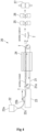
- FIGS. 1 are cross-sectional views showing the configuration of the wick 1. It is to be noted that FIG. 1(a) shows a cross section taken along a longitudinal direction of the wick 1, and FIG. 1(b) shows a cross section taken along a width direction of the wick 1.
- the wick 1 is formed into a sheet shape (a tabular shape).
- the wick 1 is formed into a rectangular sheet shape. Furthermore, of both end portions of the wick 1 in the longitudinal direction, one end portion is arranged in a heating receiving section of a heat conduction member, and the other end portion is arranged in a heat radiating section of the heat conduction member.
- the heat conduction member will be described later.
- Steam passages s through which a vaporized working fluid (steam) flows are provided on at least one surface of an upper surface and a lower surface of the wick 1.
- the steam passages s are provided on the upper surface of the wick 1.
- the steam passages s are grooves formed in a reticular pattern (a matrix pattern/line-column pattern).
- the wick 1 may be configured with no steam passages s provided thereon. When such a configuration is adopted, the steam passages are provided on a later-described container side.
- protrusions p configured to suppress boiling vibration are provided on at least one surface of the upper surface and the lower surface of the wick 1.
- the plurality of protrusions p aligned in a reticular pattern are provided on the upper surface of the wick 1. That is, on the upper surface of the wick 1, a plurality of protrusion rows each formed of the plurality of protrusions p aligned along the longitudinal direction are formed along the width direction.
- Each protrusion p is formed into a prismatic shape which protrudes upward. Further, in this embodiment, a space between two protrusions adjacent to each other constitutes the steam passage s.
- forming the steam passages s in the reticular pattern (the matrix pattern/line-column pattern) on the upper surface of the wick 1 enables forming the plurality of protrusions p aligned in the reticular pattern (the matrix pattern/line-column pattern) on the upper surface of the wick 1.
- the wick 1 may be configured with no protrusions p provided thereto.
- each steam passage s can take any shape/configuration as long as the vaporized (evaporated) working fluid can be caused to reach a portion arranged in the heat receiving section to a portion arranged in the heat radiating section in the wick 1.
- the steam passages s may be constituted by providing one or more grooves, which extend in the longitudinal direction, along the width direction.
- each steam passage s may be constituted of a space between two protrusions adjacent to each other after irregularly arranging the plurality of protrusions.
- a shape of each protrusion p may be any other shape such as a columnar shape.
- the wick 1 is made of a sintered compact and has a porous structure.
- the wick 1 is made of Cu, Fe, Ni, Cr, Ti, Al, Ag, and Sn or an alloy of these materials.
- the wick 1 is preferably made of Cu or Al.
- An average void ratio of the wick 1 (whole) preferably falls within the range of 5 to 90%. That is, when the average void ratio of the wick falls below 5%, there is a fear that voids do not become communicating holes. On the other hand, when the average void ratio of the wick 1 exceeds 90%, there is a risk that strength becomes insufficient. Thus, the average void ratio of the wick 1 preferably falls within the range of 5 to 90%, particularly the range of 10 to 70%.
- a thickness of the wick 1 preferably falls within the range of 0.05 to 1.0 mm. That is, to reduce the thickness of the wick 1 to be less than 0.05 mm, material powder must be micronized, which increases a material cost. Moreover, when the thickness of the wick 1 falls below 0.05 mm, the strength becomes insufficient, and handling becomes difficult. Additionally, with a reduction in thickness of the heat conduction material in recent years, when the thickness of the wick 1 exceeds 1.0 mm, arrangement in the heat conduction material becomes difficult. Thus, the thickness of the wick 1 preferably falls within the range of 0.05 to 1.0 mm, particularly the range of 0.1 to 0.6 mm.
- the thickness of the wick 1 refers to a dimension of a portion having a maximum thickness (a maximum dimension) in the wick 1.
- FIGS. 2 are cross-sectional views showing an example of a base.
- the material powder it is possible to use a combination of one or more metal powders (alloy powder) among Cu powder, Fe powder, Ni powder, Cr powder, Ti powder, Al powder, Ag powder, Sn powder, and the alloy powder.
- alloy powder it is possible to use alloy powder composed of one or more metals among Cu, Fe, Ni, Cr, Ti, Al, Ag, and Sn.
- a binder such as a thermoplastic resin or a wax may be added to the material powder.
- a binder such as a thermoplastic resin or wax may be added to the material powder.
- a liquid which is 0.5 ml/kg or less e.g., an oil whose viscosity is 20 mm 2 /s or less
- the segregation/size segregation can be suppressed.
- the material power is then supplied onto the base.
- the base may take any shape as long as the material powder can be mounted thereon. However, the base must be made of a material having high heat resistance such as refractory metal, ceramics, or carbon. Additionally, a surface of the base onto which the material powder is supplied is preferably flat.
- a frame body (not shown), a tray T (see FIGS. 2 , FIG. 4 , and FIG. 5 ), a metal belt 11a (see FIG. 3 ), or the like can be used.
- the tray T is configured to include a tray main body t1 and a lid body t2.
- the tray main body t1 is formed into a substantially rectangular box shape (a frame shape) whose upper surface is opened so that it can be filled with the material powder.
- the lid body t2 is formed into a substantially rectangular tabular shape so that the upper surface of the tray main body t1 can be closed. Since the tray T includes the lid body t2, the material powder filled in the tray main body t1 can be prevented from scattering.
- the material powder can be accommodated in the tray main body t1 in an uncompressed state.
- the material powder can be accommodated in the tray main body t1 in a slightly compressed state.
- the material powder which has been supplied onto the base is smoothened.
- a thickness (a height) of the material powder which has been supplied onto the base is uniformized.
- the material powder which has been supplied onto the base can be smoothened with the use of smoothening means such as a plate material or a roller.
- the tray T As the base, after filling the tray main body t1 with the material powder, leveling off the excess material powder with the upper end portion of the tray main body t1 determined as a reference by using the plate material enables smoothening the material powder. Then, to prevent the material powder from moving or scattering, the lid body t2 is put.
- the material powder can be smoothened by using a roller 13.
- the metal belt 11a may be formed into a concave shape (a frame shape) .
- bulk density of the material powder before sintering is preferably set to fall within the range of 10 to 50% to true density (material density with no void), particularly the range of 15 to 35% to the true density.
- a thickness of the material powder before sintering preferably falls within the range of 0.1 to 2.0 mm, particularly the range of 0.15 to 1.5 mm.
- the material powder which has been supplied onto the base is sintered (heated).
- the material powder on the base is sintered in a predetermined sintering atmosphere/at a predetermined sintering temperature to form a sintered compact.
- the material powder is sintered, metal particles adjacent to each other are subjected to the diffusion bonding, and the metal particles are coupled to form the porous sintered compact.
- a vacuum, a neutral gas (a nitrogen gas, an argon gas, or the like), a reducing gas (an ammonia decomposition gas, a hydrogen gas, an endothermic gas, or the like), or the like is appropriately selected in correspondence with a composition of the material powder.
- the sintering temperature is appropriately selected in the range of 400 to 1050°C in correspondence with the composition of the material powder.
- the ammonia decomposition gas is preferably selected as the sintering atmosphere, and a temperature in the range of 800 to 1050°C is preferably selected as the sintering temperature.
- the sintered compact taken out from the base is then rolled.
- the sintered compact is rolled by using a rolling apparatus.
- Rolling the sintered compact enables reducing a thickness of the sintered compact, uniformizing the thickness of the sintered compact, improving surface roughness of the sintered compact, and increasing sintering density.
- rolling the sintered compact enables controlling the thickness/density/void ratio of the sintered compact and controlling a thickness/density/void ratio/capillarity of the wick 1.
- the rolling apparatus is configured to include a pair of rollers arranged at a predetermined interval. At the time of rolling, each roller is rotated. Additionally, the sintered compact passes between the pair of rollers, whereby it is rolled with a desired thickness and desired density.
- one rolling apparatus alone may be used to roll the sintered compact, or a plurality of rolling apparatuses may be used to roll the sintered compact in a step-by-step manner.
- the sintered compact may be rolled by the rolling apparatus while being heated at a predetermined heating temperature.
- the heating temperature is appropriately selected in correspondence with the composition of the material powder.
- an average void ratio of the sintered compact (whole) after rolling preferably falls within the range of 5 to 90%, particularly the range of 10 to 70%.
- the thickness of the sintered compact after rolling preferably falls within the range of 0.05 to 1.0 mm, particularly the range of 0.1 to 0. 6 mm.
- the thickness of the sintered compact after rolling refers to a dimension of a portion having a maximum thickness (a maximum dimension) in the sintered compact.
- steam passages s, protrusions p, and the like are formed. They can be formed by press working, machining, etching processing, or the like.
- the wick 1 is formed.
- FIG. 3 is a view showing the first example of the manufacturing line of the wick 1.
- the wick 1 can be manufactured with the use of, e.g., the manufacturing line 10 shown in FIG. 3 .
- the manufacturing line 10 is configured to include a belt conveyer 11, a hopper 12, a roller 13, a sintering furnace 14, rolling apparatuses 15 and 16, and a cutting apparatus 17.
- the belt conveyer 11 is configured to include a metal belt 11a which circulates by rotation of a truck.
- the metal belt 11a is made of a refractory metal.
- the hopper 12 is configured to include a storage tank 12a which stores the material powder. Further, the hopper 12 supplies the material powder stored in the storage tank 12a onto an upper surface of the metal belt 11a. At this moment, the hopper 12 operates in such a manner that an amount of the material powder supplied per unit time becomes fixed.
- the roller 13 is arranged above the metal belt 11a so that its rotation shaft extends along a direction orthogonal to a traveling direction of the metal belt 11a.
- the roller 13 is arranged in such a manner that an interval between the metal belt 11a and itself becomes a predetermined interval.
- the sintering furnace 14 is formed into a box shape, and constituted in such a manner that the metal belt 11a passes through the inside thereof.
- a heater is arranged so that the material powder arranged on the metal belt 11a can be heated in a predetermined atmosphere.
- Each of the rolling apparatuses 15 and 16 is configured to include a pair of rollers.
- the sintered compact is rolled by the two rolling apparatuses 15 and 16 in a step-by-step manner.
- the cutting apparatus 17 is configured to include a pair of cutting blades .
- the pair of cutting blades are opened and closed at a predetermined cycle. Consequently, the sintered compact passes between the pair of cutting blades to be cut into a desired length.
- the material powder is first supplied onto the upper surface of the metal belt 11a by the hopper 12 (a filling apparatus).
- the material powder supplied to the upper surface of the metal belt 11a is carried from the upstream side toward the downstream side by the circulation of the metal belt 11a.
- the material powder which has been supplied onto the upper surface of the metal belt 11a first passes underneath the roller 12. At this moment, the material powder supplied onto the upper surface of the metal belt 11a is smoothened by an outer peripheral surface of the roller 12, and a thickness (a height) of the material power is uniformized.
- the material powder arranged on the upper surface of the metal belt 11a then passes through the inside of the sintering furnace 14. At this moment, the material powder supplied onto the upper surface of the metal belt 11a is heated by the heater, and a sintered compact is formed.
- the sintered compact arranged on the upper surface of the metal belt 11a then passes through the respective rolling apparatuses 15 and 16. At this moment, the sintered compact is rolled by the respective rolling apparatuses 15 and 16.
- the sintered compact arranged on the upper surface of the metal belt 11a then passes through the cutting apparatus 17. At this moment, the sintered compact is cut into a desired length by the pair of cutting blades.
- processing to form steam passages s, protrusions p, and the like is performed to the sintered compact. It is to be noted that, the processing to form the steam passages s, the protrusions p, and the like may be performed to the sintered compact before passing through the cutting apparatus 17.
- the wick 1 is manufactured.
- FIG. 4 is a view showing the second example of the manufacturing line of the wick 1.
- the wick 1 can be likewise manufactured with the use of a manufacturing line 20 shown in FIG. 4 .
- the manufacturing line 20 is configured to include a belt conveyer 21, a filling apparatus 22, a filling base 23, a sintering furnace 24, rolling apparatuses 25 and 26, and a press apparatus 27.
- the filling base 23 is configured to include a tray installing section on which a tray T can be installed (mounted).
- the filling apparatus 22 is configured to include a storage tank 22a which stores the material powder and a powder box 22b which reciprocate on an upper surface of the filling base 23.
- the powder box 22b is formed in to a box shape so that the material powder can be accommodated therein. Furthermore, one or more opening portions (through holes) are provided in a bottom surface of the powder box 22b. In this embodiment, each opening portion is formed into a slit shape extending in a direction orthogonal to a traveling direction of the powder box 22b. Moreover, the plurality of opening portions which are parallel to each other are provided in the bottom surface of the powder box 22b. It is to be noted that the number/shape/size of the opening portions can be appropriately set.
- the material powder stored in the storage tank 22a is supplied into the powder box 22b through a hose 22c. Additionally, the powder box 22b is reciprocated on an upper surface of the filling base 23 along a predetermined direction by a non-illustrated driving mechanism. At this moment, when the powder box 22b passes above the tray T installed on the tray installing section, the material powder accommodated in the powder box 22b is caused to fill the tray T by its own weight through the opening portions.
- the belt conveyer 21 is configured to include a metal belt 21a which circulates by rotation of a track. Further, the belt conveyer 21 can carry the tray T arranged on the metal belt 21a by the circulation of the metal belt 21a.
- the sintering furnace 24 is formed into a box shape, and configured in such a manner that the tray T installed on the metal belt 21a can pass through the inside thereof.
- a heater is arranged, and the material powder filling the tray T can be heated in a predetermined atmosphere.
- Each of the rolling apparatuses 25 and 26 is configured to include a pair of rollers. Each of the rolling apparatuses 25 and 26 can roll the sintered compact by the pair of rollers.
- the press apparatus 27 is configured to include a pair of press molds . Furthermore, the press apparatus 27 can form steam passages s, protrusions p, and the like on the sintered compact by opening/closing (compression) of the pair of press molds.
- the empty tray T is first installed on the tray installing section of the filling base 23.
- the tray T installed on the tray installing section is filled with the material powder by the filling apparatus 22. That is, on the upper surface of the filling base 23, the powder box 22b is reciprocated. Consequently, the tray T installed on the tray installing section is filled with the material powder in the powder box 22b.
- a plate material is used to level off the excess material powder with an upper end portion of a tray main body t1 determined as a reference, and then a lid body t2 is put.
- the excess material powder may be leveled off by the reciprocation of the powder box 22b with the upper end portion of the tray main body t1 determined as a reference.
- the tray T is installed on the upper surface of the metal belt 21a. Consequently, the tray T is carried from the upstream side toward the downstream side by the circulation of the metal belt 21a.
- the tray T carried by the metal belt 21a passes through the inside of the sintering furnace 24. At this moment, the material powder filling the tray T is heated by a heater 24, thereby forming a sintered compact.
- the sintered compact is taken out from the tray T, and the taken-out sintered compact is rolled by the respective rolling apparatuses 25 and 26 in a step-by-step manner. Consequently, the sintered compact can have a desired thickness/average void ratio.
- the rolled sintered compact is compressed by the press apparatus 27. Consequently, steam passages s, protrusions p, and the like are formed on the sintered compact.
- the wick 1 is manufactured.
- FIG. 5 is a view showing the third example of the manufacturing line of the wick 1.
- the wick 1 can be likewise manufactured by the manufacturing line 30 shown in FIG. 5 .
- a basic configuration of the manufacturing line 30 is the same as the manufacturing line.
- the same structures as those in the manufacturing line 20 are denoted by the same reference signs to omit a description thereof.
- the manufacturing line 30 is different from the manufacturing line 20 in that a vertical sintering furnace 34 is arranged in place of the horizontal sintering furnace 24.
- a carrier apparatus 31 is arranged in place of the belt conveyer 21 in the manufacturing line 30.
- the carrier apparatus 31 is configured to include circulating means 31a, and a plurality of tray mounting sections 31b which are circulated by rotation of the circulating means 31a. Further, the carrier apparatus 31 can carry trays T mounted on the respective tray mounting sections 31b upward (toward a vertical direction).
- the sintering furnace 34 is formed into a box shape so that the trays T mounted on the respective mounting sections 31b can pass through the inside thereof.
- a heater is arranged so that material powder filling the trays T can be heated in a predetermined atmosphere.
- the empty trays T are first installed on the tray installing sections of a filling base 23.
- the trays T installed on the tray installing sections are filled with the material powder by a filling apparatus 22.
- a plate material is used to level off the excess material powder with an upper end portion of each tray main body t1 determined as a reference, and a lid body t2 is put.
- the trays T are installed on upper surfaces of the tray mounting sections 31a. Consequently, the trays T are carried upward by rotation (circulation) of the circulating means 31a.
- the trays T carried upward pass through the inside of the sintering furnace 24. At this moment, the material powder filling the trays T is heated by the heater 34, thereby forming sintered compacts.
- the sintered compacts are taken out from the trays T, and the taken-out sintered compacts are rolled by respective rolling apparatuses 25 and 26 by a step-by-step manner. Consequently, the sintered compacts can have a desired thickness/average void ratio.
- the rolled sintered compacts are compressed by a press apparatus 27. Consequently, steam passages s, protrusions p, and the like are formed on the sintered compacts.
- the wick 1 is manufactured.
- the vertical sintering furnace 34 is applied, and the trays T are carried along the vertical direction by the carrier apparatus 31 (according to an elevator system) . Consequently, as compared with the manufacturing line 20, space saving of the facilities can be achieved.
- apparent density of the material powder before sintering changes in correspondence with a state of the material powder such as a composition (a lot) of the material powder or a working environment where the material powder is handled.
- a state of the material powder such as a composition (a lot) of the material powder or a working environment where the material powder is handled.
- natural filling density of the material powder before sintering must be adjusted (changed) in correspondence with a state of the material powder.
- sintering jigs e.g., changing a thickness of the frame body or changing a depth of the tray T enables adjusting the natural filling density of the material powder before sintering.
- preparing the sintering jigs having different configurations in accordance with a state of the material powder is not realistic.
- a mechanism which adjusts (changes) a powder height (a storage amount) of the material powder stored in the storage tank 12a of the hopper 12 may be provided.
- adjusting a weight of the material powder itself stored in the storage tank 12a enables adjusting bulk density (filling bulk density) of the material powder which is supplied (filled) onto the base (the metal belt 11a).
- a mechanism which adjusts (changes) a powder height (a storage height) of the material powder accommodated (stored) in the powder box 22b of the filling apparatus 22 may be provided.
- adjusting a weight of the material powder itself accommodated in the powder box 22b enables adjusting the bulk density (the filling bulk density) of the material powder supplied (filled) onto the base (the tray T).
- the wick 1 can be applied (used) to a heat conduction member (a heat radiation member) such as a heat pipe or a vapor chamber.
- a heat conduction member a heat radiation member
- the heat conduction member (not shown) is configured to include a container, a working fluid, and the wick 1.
- the container is configured to seal (hermetically contain) the working fluid and the wick 1 therein.
- a shape of the container a cylindrical shape, a flat shape, or the like is appropriately selected in correspondence with an intended use.
- the container is made of a material with a high heat conductivity such as Cu or Al.
- the container according to this embodiment is a rectangular sheet-shaped case made of native copper. Furthermore, in the container, one end portion of both end portions along the longitudinal direction is determined as a heat receiving section, and the other end portion is determined as a heat radiating section.
- the working fluid it is possible to use water (H2O), helium (He), nitrogen (N2), Freon 22 (CHCIF2), HFC-134a (CH2F-CF3), ammonia (NH3), Freon 113 (CCI2F-CCIF2), HCFC-123 (1, 1-dichloro-2, 2, 2-trifluoroethane), aceton (C3H6O), methanol (CH4O), dowthermA ((C6H5)2+(C6H5)20), naphthalene (C10H8), cesium (Cs), natrium (Na), lithium (Li), silver (Ag), or the like.
- the container is formed by bonding a plate material made of native copper, a sheet material, or the like in a bag-like shape by sputtering, welding, or the like.
- the wick 1 and the working fluid are sealed in the container.
- the wick 1 and the working fluid are sealed in the container in a state where the inside of the container is vacuum-deaired. Consequently, the inside of the wick having the porous structure is impregnated with the working fluid.
- the wick 1 is arranged along the container. That is, in the container, one end portion of both the end portions in the longitudinal direction of the wick 1 is arranged in the heat receiving section, and the other end portion is arranged in the heat radiating section.
- the heat receiving section of the heat conduction member is arranged in a state where it adheres to a heating body such as a CPU through heat conductive grease. Consequently, heat of the heating body is conducted to the heat receiving section.
- the working fluid is heated by the heat conducted to the heat receiving section, and the heated working fluid is vaporized (evaporated). Moreover, the working fluid vaporized by the heat receiving section passes through the steam passages s and flows into the heat radiating section.
- the heat radiating section has a relatively low temperature with respect to the heat receiving section. Consequently, the working fluid which has flowed into the heat radiating section is cooled by the heat radiating section, and the cooled working fluid is liquefied (condensed). At this moment, the heat conducted from the heating body is discharged as latent heat.
- the working fluid liquefied in the heat radiating section is absorbed into the wick 1 by the capillarity of the wick 1, passes through the inside of the wick, and is refluxed from the heat radiating section to the heat receiving section.
- repeating the circulation of the working fluid enables continuing movement of the heat from the heat receiving section to the heat radiating section, thereby continuously discharging the heat of the heating body.
- the heat conduction member can be applied to cooling of various kinds of electronic devices (a personal computer, a mobile terminal, and the like), cooling of a nickel-metal-hydride battery or a lithium battery used in a car, or the like.
- the sintered compact is formed by heating the material powder supplied onto the base. Consequently, the sheet-shaped sintered compact can be formed.
- the sintered compact is rolled. Consequently, after forming the sintered compact, a void ratio of the sintered compact can be controlled, thereby controlling the capillarity of the wick 1. In particular, after forming the sintered compact, a thickness of the sheet-shaped sintered compact can be controlled, thereby reducing a thickness of the wick 1.
- the material powder supplied onto the base is smoothened. Consequently, in the rolled sintered compact, the density can be prevented from becoming nonuniform, thus avoiding the nonuniform capillarity of the wick 1.
- the steam passages s, the protrusions p, and the like are formed on the surface of the rolled sintered compact. Consequently, in the sintered compact having the porous structure, since the steam passages s, the protrusions p, and the like are formed, the steam passages s, the protrusions p, and the like can be easily formed as compared with a case where the steam passages are formed on the container side.
- the container of the heat conduction member and the wick 1 can be individually formed. Consequently, it is not necessary to take a method for forming the wick in the container by externally heating the container after filling the container with the metal powder, and deterioration of the container due to heating can be avoided.
Landscapes
- Engineering & Computer Science (AREA)
- Mechanical Engineering (AREA)
- General Engineering & Computer Science (AREA)
- Thermal Sciences (AREA)
- Physics & Mathematics (AREA)
- Manufacturing & Machinery (AREA)
- Sustainable Development (AREA)
- Life Sciences & Earth Sciences (AREA)
- Chemical & Material Sciences (AREA)
- Composite Materials (AREA)
- Materials Engineering (AREA)
- Powder Metallurgy (AREA)
- Cooling Or The Like Of Semiconductors Or Solid State Devices (AREA)
- Organic Low-Molecular-Weight Compounds And Preparation Thereof (AREA)
Applications Claiming Priority (2)
| Application Number | Priority Date | Filing Date | Title |
|---|---|---|---|
| JP2018051832A JP2019163895A (ja) | 2018-03-19 | 2018-03-19 | ウィックの製造方法 |
| PCT/JP2019/009617 WO2019181598A1 (ja) | 2018-03-19 | 2019-03-11 | ウィックの製造方法 |
Publications (4)
| Publication Number | Publication Date |
|---|---|
| EP3770541A1 EP3770541A1 (en) | 2021-01-27 |
| EP3770541A4 EP3770541A4 (en) | 2021-12-01 |
| EP3770541C0 EP3770541C0 (en) | 2024-05-01 |
| EP3770541B1 true EP3770541B1 (en) | 2024-05-01 |
Family
ID=67986175
Family Applications (1)
| Application Number | Title | Priority Date | Filing Date |
|---|---|---|---|
| EP19770441.4A Active EP3770541B1 (en) | 2018-03-19 | 2019-03-11 | Wick manufacturing method |
Country Status (7)
Families Citing this family (4)
| Publication number | Priority date | Publication date | Assignee | Title |
|---|---|---|---|---|
| JP7608227B2 (ja) | 2021-03-22 | 2025-01-06 | 古河電気工業株式会社 | 冷却装置の蒸発面構造およびその製造方法ならびに冷却装置およびヒートパイプ |
| KR20240012365A (ko) * | 2021-03-26 | 2024-01-29 | 유니버시티 오브 매릴랜드, 칼리지 파크 | 고온 소결 용광로 시스템 및 방법 |
| JP7233584B1 (ja) | 2022-02-28 | 2023-03-06 | 古河電気工業株式会社 | ベーパーチャンバ |
| CN115178738A (zh) * | 2022-07-13 | 2022-10-14 | 航天科工哈尔滨风华有限公司 | 一种用于烧结金属粉末吸液芯的装置及方法 |
Family Cites Families (32)
| Publication number | Priority date | Publication date | Assignee | Title |
|---|---|---|---|---|
| US3762011A (en) * | 1971-12-16 | 1973-10-02 | Trw Inc | Method of fabricating a capillary heat pipe wick |
| JPS5798430A (en) * | 1980-12-11 | 1982-06-18 | Mitsubishi Metal Corp | Automatic conveying apparatus for molded bodies |
| DE3840413C1 (en) * | 1988-11-30 | 1990-04-19 | Siemens Ag, 1000 Berlin Und 8000 Muenchen, De | Installation for sheathing electrical components in plastic by the fluidised bed coating process |
| TW387826B (en) * | 1997-03-11 | 2000-04-21 | Katayama Tokushu Kogyo Kk | Method of manufacturing porous sheet porous metal sheet manufactured by method, and electrode for battery |
| JP2000054159A (ja) * | 1998-08-07 | 2000-02-22 | Hitachi Chem Co Ltd | 伝熱材及び伝熱体並びに伝熱材の製造方法及び伝熱体の製造方法 |
| CN1139781C (zh) * | 2000-04-30 | 2004-02-25 | 中国石油化工集团公司 | 一种高热通量换热管及其制造方法 |
| JP2002022380A (ja) * | 2000-07-07 | 2002-01-23 | Fujikura Ltd | エンボスウィックを備えた平板型ヒートパイプ |
| JP2003155503A (ja) * | 2001-11-15 | 2003-05-30 | Mitsubishi Materials Corp | 多孔質金属体の製造方法 |
| JP4259123B2 (ja) * | 2003-01-28 | 2009-04-30 | パナソニック電工株式会社 | 三次元形状造形物の製造方法 |
| JP4300871B2 (ja) * | 2003-05-09 | 2009-07-22 | 三菱マテリアル株式会社 | シート状多孔質金属体の製造方法 |
| JP2005229049A (ja) * | 2004-02-16 | 2005-08-25 | Internatl Business Mach Corp <Ibm> | ベーパ・チャンバ及びその製造方法、冷却装置、並びにコンピュータ |
| CN100386588C (zh) * | 2004-12-30 | 2008-05-07 | 南京理工大学 | 两相毛细泵环路复合毛细芯及其制备方法 |
| TWI261659B (en) * | 2005-03-25 | 2006-09-11 | Delta Electronics Inc | Manufacturing method of heat dissipation apparatus |
| JP2007017038A (ja) * | 2005-07-06 | 2007-01-25 | Fujikura Ltd | ヒートパイプおよびその製造方法 |
| KR20100007897A (ko) * | 2007-06-15 | 2010-01-22 | 아사히 가세이 셍이 가부시키가이샤 | 루프 히트 파이프형 전열 장치 |
| JP2009092344A (ja) * | 2007-10-11 | 2009-04-30 | Hitachi Metals Ltd | 熱輸送特性に優れたベーパチャンバ |
| TWI427256B (zh) * | 2009-02-13 | 2014-02-21 | Foxconn Tech Co Ltd | 熱管及其毛細結構之製作方法 |
| TW201042228A (en) * | 2009-05-19 | 2010-12-01 | Tai Sol Electronics Co Ltd | Method for disposing capillary material in heat pipe |
| US8231827B2 (en) * | 2009-06-17 | 2012-07-31 | The Gates Corporation | Method of manufacturing powder metal plates |
| JP5568289B2 (ja) * | 2009-11-30 | 2014-08-06 | 新光電気工業株式会社 | 放熱部品及びその製造方法 |
| JP5526941B2 (ja) * | 2010-03-31 | 2014-06-18 | 三菱マテリアル株式会社 | アルミニウム多孔質焼結体の製造方法 |
| CN201715908U (zh) * | 2010-06-07 | 2011-01-19 | 锘威科技(深圳)有限公司 | 一体式烧结型平板热管 |
| JP5902404B2 (ja) * | 2011-06-10 | 2016-04-13 | 株式会社フジクラ | 扁平型ヒートパイプおよびその製造方法 |
| JP2013072135A (ja) * | 2011-09-29 | 2013-04-22 | Toho Titanium Co Ltd | シート状多孔体の製造方法 |
| TW201333407A (zh) * | 2012-02-13 | 2013-08-16 | Hao Pai | 板狀熱管之毛細組織成形方法及其成品(二) |
| TWI582364B (zh) * | 2012-04-16 | 2017-05-11 | 鴻準精密工業股份有限公司 | 熱管殼體的製造方法 |
| CN103372650B (zh) * | 2012-04-16 | 2016-12-14 | 富瑞精密组件(昆山)有限公司 | 热管壳体的制造方法 |
| JP6147969B2 (ja) | 2012-07-05 | 2017-06-14 | 株式会社フジクラ | ヒートパイプのウイック構成体の製造方法 |
| JP6033029B2 (ja) | 2012-10-01 | 2016-11-30 | 株式会社フジクラ | ウイックの製造方法 |
| JP5713058B2 (ja) * | 2013-07-12 | 2015-05-07 | 三菱マテリアル株式会社 | 金属多孔質体の製造方法 |
| JP6668649B2 (ja) * | 2015-09-17 | 2020-03-18 | 株式会社リコー | 立体造形装置、プログラム |
| WO2017089960A1 (en) * | 2015-11-23 | 2017-06-01 | Victoria Link Ltd | Microstructured surfaces for enhanced phase change heat transfer |
-
2018
- 2018-03-19 JP JP2018051832A patent/JP2019163895A/ja active Pending
-
2019
- 2019-03-11 WO PCT/JP2019/009617 patent/WO2019181598A1/ja unknown
- 2019-03-11 KR KR1020207023859A patent/KR102622534B1/ko active Active
- 2019-03-11 CN CN201980011770.7A patent/CN111684231B/zh active Active
- 2019-03-11 US US16/982,913 patent/US12064815B2/en active Active
- 2019-03-11 EP EP19770441.4A patent/EP3770541B1/en active Active
- 2019-03-18 TW TW108109121A patent/TWI812686B/zh active
-
2024
- 2024-06-07 US US18/736,877 patent/US20240316639A1/en active Pending
Also Published As
| Publication number | Publication date |
|---|---|
| TW201940830A (zh) | 2019-10-16 |
| KR20200128521A (ko) | 2020-11-13 |
| US20210016354A1 (en) | 2021-01-21 |
| US12064815B2 (en) | 2024-08-20 |
| CN111684231A (zh) | 2020-09-18 |
| EP3770541C0 (en) | 2024-05-01 |
| WO2019181598A1 (ja) | 2019-09-26 |
| JP2019163895A (ja) | 2019-09-26 |
| EP3770541A1 (en) | 2021-01-27 |
| EP3770541A4 (en) | 2021-12-01 |
| US20240316639A1 (en) | 2024-09-26 |
| TWI812686B (zh) | 2023-08-21 |
| CN111684231B (zh) | 2023-02-28 |
| KR102622534B1 (ko) | 2024-01-09 |
Similar Documents
| Publication | Publication Date | Title |
|---|---|---|
| US20240316639A1 (en) | Method for manufacturing wick | |
| CN109014218B (zh) | 烧结轴承 | |
| EP1160860B1 (en) | Heat sink material and manufacturing method thereof | |
| CN111414056A (zh) | 带有结构化芯吸部的超薄两相热交换器 | |
| Huang et al. | An anti-leakage liquid metal thermal interface material | |
| EP2962791B1 (en) | Porous aluminum sintered compact | |
| US20090294104A1 (en) | Vapor chamber | |
| US9555473B2 (en) | System and method for increasing the bulk density of metal powder | |
| US9702028B2 (en) | Magnesium-based alloy powder and magnesium-based alloy molded article | |
| AT524235B1 (de) | Wärmetransportvorrichtung | |
| EP1333710A3 (en) | Method and apparatus for absorbing thermal energy | |
| WO2016014654A1 (en) | Monolithic porous open-cell structures | |
| US20150004041A1 (en) | Method for manufacturing porous aluminum | |
| JP5526941B2 (ja) | アルミニウム多孔質焼結体の製造方法 | |
| US10035187B2 (en) | Aluminum material for sintering, method for producing aluminum material for sintering, and method for producing porous aluminum sintered compact | |
| US20140144609A1 (en) | Evaporator for looped heat pipe system and method of manufacturing the same | |
| CN211147408U (zh) | 热管 | |
| CN103443315A (zh) | 包含由复合材料制成的衬底的复合构件 | |
| Xin et al. | Development of sintered Ni-Cu wicks for loop heat pipes | |
| Mishra et al. | Studies on the processing of nickel base porous wicks for capillary pumped loop for thermal management of spacecrafts | |
| JPH11248097A (ja) | 水素吸蔵合金の容器およびその製造方法 | |
| JP5526940B2 (ja) | アルミニウム多孔質焼結体の製造方法 | |
| CN117039238A (zh) | 电池组件 | |
| JP2004221605A (ja) | ヒートシンク材及びその製造方法 | |
| RU2106931C1 (ru) | Способ получения изделий из пористого бериллия |
Legal Events
| Date | Code | Title | Description |
|---|---|---|---|
| STAA | Information on the status of an ep patent application or granted ep patent |
Free format text: STATUS: THE INTERNATIONAL PUBLICATION HAS BEEN MADE |
|
| PUAI | Public reference made under article 153(3) epc to a published international application that has entered the european phase |
Free format text: ORIGINAL CODE: 0009012 |
|
| STAA | Information on the status of an ep patent application or granted ep patent |
Free format text: STATUS: REQUEST FOR EXAMINATION WAS MADE |
|
| 17P | Request for examination filed |
Effective date: 20200714 |
|
| AK | Designated contracting states |
Kind code of ref document: A1 Designated state(s): AL AT BE BG CH CY CZ DE DK EE ES FI FR GB GR HR HU IE IS IT LI LT LU LV MC MK MT NL NO PL PT RO RS SE SI SK SM TR |
|
| AX | Request for extension of the european patent |
Extension state: BA ME |
|
| DAV | Request for validation of the european patent (deleted) | ||
| DAX | Request for extension of the european patent (deleted) | ||
| A4 | Supplementary search report drawn up and despatched |
Effective date: 20211102 |
|
| RIC1 | Information provided on ipc code assigned before grant |
Ipc: F28F 21/08 20060101ALI20211026BHEP Ipc: F28D 15/02 20060101ALI20211026BHEP Ipc: B22F 3/18 20060101ALI20211026BHEP Ipc: F28D 15/04 20060101AFI20211026BHEP |
|
| GRAP | Despatch of communication of intention to grant a patent |
Free format text: ORIGINAL CODE: EPIDOSNIGR1 |
|
| STAA | Information on the status of an ep patent application or granted ep patent |
Free format text: STATUS: GRANT OF PATENT IS INTENDED |
|
| INTG | Intention to grant announced |
Effective date: 20231004 |
|
| GRAJ | Information related to disapproval of communication of intention to grant by the applicant or resumption of examination proceedings by the epo deleted |
Free format text: ORIGINAL CODE: EPIDOSDIGR1 |
|
| STAA | Information on the status of an ep patent application or granted ep patent |
Free format text: STATUS: REQUEST FOR EXAMINATION WAS MADE |
|
| GRAP | Despatch of communication of intention to grant a patent |
Free format text: ORIGINAL CODE: EPIDOSNIGR1 |
|
| STAA | Information on the status of an ep patent application or granted ep patent |
Free format text: STATUS: GRANT OF PATENT IS INTENDED |
|
| INTC | Intention to grant announced (deleted) | ||
| GRAS | Grant fee paid |
Free format text: ORIGINAL CODE: EPIDOSNIGR3 |
|
| INTG | Intention to grant announced |
Effective date: 20240226 |
|
| GRAA | (expected) grant |
Free format text: ORIGINAL CODE: 0009210 |
|
| STAA | Information on the status of an ep patent application or granted ep patent |
Free format text: STATUS: THE PATENT HAS BEEN GRANTED |
|
| AK | Designated contracting states |
Kind code of ref document: B1 Designated state(s): AL AT BE BG CH CY CZ DE DK EE ES FI FR GB GR HR HU IE IS IT LI LT LU LV MC MK MT NL NO PL PT RO RS SE SI SK SM TR |
|
| REG | Reference to a national code |
Ref country code: GB Ref legal event code: FG4D |
|
| REG | Reference to a national code |
Ref country code: CH Ref legal event code: EP |
|
| REG | Reference to a national code |
Ref country code: DE Ref legal event code: R096 Ref document number: 602019051454 Country of ref document: DE |
|
| REG | Reference to a national code |
Ref country code: IE Ref legal event code: FG4D |
|
| U01 | Request for unitary effect filed |
Effective date: 20240515 |
|
| U07 | Unitary effect registered |
Designated state(s): AT BE BG DE DK EE FI FR IT LT LU LV MT NL PT SE SI Effective date: 20240527 |
|
| PG25 | Lapsed in a contracting state [announced via postgrant information from national office to epo] |
Ref country code: IS Free format text: LAPSE BECAUSE OF FAILURE TO SUBMIT A TRANSLATION OF THE DESCRIPTION OR TO PAY THE FEE WITHIN THE PRESCRIBED TIME-LIMIT Effective date: 20240901 |
|
| PG25 | Lapsed in a contracting state [announced via postgrant information from national office to epo] |
Ref country code: HR Free format text: LAPSE BECAUSE OF FAILURE TO SUBMIT A TRANSLATION OF THE DESCRIPTION OR TO PAY THE FEE WITHIN THE PRESCRIBED TIME-LIMIT Effective date: 20240501 |
|
| PG25 | Lapsed in a contracting state [announced via postgrant information from national office to epo] |
Ref country code: GR Free format text: LAPSE BECAUSE OF FAILURE TO SUBMIT A TRANSLATION OF THE DESCRIPTION OR TO PAY THE FEE WITHIN THE PRESCRIBED TIME-LIMIT Effective date: 20240802 |
|
| PG25 | Lapsed in a contracting state [announced via postgrant information from national office to epo] |
Ref country code: ES Free format text: LAPSE BECAUSE OF FAILURE TO SUBMIT A TRANSLATION OF THE DESCRIPTION OR TO PAY THE FEE WITHIN THE PRESCRIBED TIME-LIMIT Effective date: 20240501 |
|
| PG25 | Lapsed in a contracting state [announced via postgrant information from national office to epo] |
Ref country code: PL Free format text: LAPSE BECAUSE OF FAILURE TO SUBMIT A TRANSLATION OF THE DESCRIPTION OR TO PAY THE FEE WITHIN THE PRESCRIBED TIME-LIMIT Effective date: 20240501 |
|
| PG25 | Lapsed in a contracting state [announced via postgrant information from national office to epo] |
Ref country code: PL Free format text: LAPSE BECAUSE OF FAILURE TO SUBMIT A TRANSLATION OF THE DESCRIPTION OR TO PAY THE FEE WITHIN THE PRESCRIBED TIME-LIMIT Effective date: 20240501 Ref country code: NO Free format text: LAPSE BECAUSE OF FAILURE TO SUBMIT A TRANSLATION OF THE DESCRIPTION OR TO PAY THE FEE WITHIN THE PRESCRIBED TIME-LIMIT Effective date: 20240801 Ref country code: IS Free format text: LAPSE BECAUSE OF FAILURE TO SUBMIT A TRANSLATION OF THE DESCRIPTION OR TO PAY THE FEE WITHIN THE PRESCRIBED TIME-LIMIT Effective date: 20240901 Ref country code: HR Free format text: LAPSE BECAUSE OF FAILURE TO SUBMIT A TRANSLATION OF THE DESCRIPTION OR TO PAY THE FEE WITHIN THE PRESCRIBED TIME-LIMIT Effective date: 20240501 Ref country code: GR Free format text: LAPSE BECAUSE OF FAILURE TO SUBMIT A TRANSLATION OF THE DESCRIPTION OR TO PAY THE FEE WITHIN THE PRESCRIBED TIME-LIMIT Effective date: 20240802 Ref country code: ES Free format text: LAPSE BECAUSE OF FAILURE TO SUBMIT A TRANSLATION OF THE DESCRIPTION OR TO PAY THE FEE WITHIN THE PRESCRIBED TIME-LIMIT Effective date: 20240501 Ref country code: RS Free format text: LAPSE BECAUSE OF FAILURE TO SUBMIT A TRANSLATION OF THE DESCRIPTION OR TO PAY THE FEE WITHIN THE PRESCRIBED TIME-LIMIT Effective date: 20240801 |
|
| PG25 | Lapsed in a contracting state [announced via postgrant information from national office to epo] |
Ref country code: CZ Free format text: LAPSE BECAUSE OF FAILURE TO SUBMIT A TRANSLATION OF THE DESCRIPTION OR TO PAY THE FEE WITHIN THE PRESCRIBED TIME-LIMIT Effective date: 20240501 |
|
| PG25 | Lapsed in a contracting state [announced via postgrant information from national office to epo] |
Ref country code: SK Free format text: LAPSE BECAUSE OF FAILURE TO SUBMIT A TRANSLATION OF THE DESCRIPTION OR TO PAY THE FEE WITHIN THE PRESCRIBED TIME-LIMIT Effective date: 20240501 Ref country code: RO Free format text: LAPSE BECAUSE OF FAILURE TO SUBMIT A TRANSLATION OF THE DESCRIPTION OR TO PAY THE FEE WITHIN THE PRESCRIBED TIME-LIMIT Effective date: 20240501 |
|
| PG25 | Lapsed in a contracting state [announced via postgrant information from national office to epo] |
Ref country code: SM Free format text: LAPSE BECAUSE OF FAILURE TO SUBMIT A TRANSLATION OF THE DESCRIPTION OR TO PAY THE FEE WITHIN THE PRESCRIBED TIME-LIMIT Effective date: 20240501 |
|
| PG25 | Lapsed in a contracting state [announced via postgrant information from national office to epo] |
Ref country code: SM Free format text: LAPSE BECAUSE OF FAILURE TO SUBMIT A TRANSLATION OF THE DESCRIPTION OR TO PAY THE FEE WITHIN THE PRESCRIBED TIME-LIMIT Effective date: 20240501 Ref country code: SK Free format text: LAPSE BECAUSE OF FAILURE TO SUBMIT A TRANSLATION OF THE DESCRIPTION OR TO PAY THE FEE WITHIN THE PRESCRIBED TIME-LIMIT Effective date: 20240501 Ref country code: RO Free format text: LAPSE BECAUSE OF FAILURE TO SUBMIT A TRANSLATION OF THE DESCRIPTION OR TO PAY THE FEE WITHIN THE PRESCRIBED TIME-LIMIT Effective date: 20240501 Ref country code: CZ Free format text: LAPSE BECAUSE OF FAILURE TO SUBMIT A TRANSLATION OF THE DESCRIPTION OR TO PAY THE FEE WITHIN THE PRESCRIBED TIME-LIMIT Effective date: 20240501 |
|
| REG | Reference to a national code |
Ref country code: DE Ref legal event code: R097 Ref document number: 602019051454 Country of ref document: DE |
|
| PLBE | No opposition filed within time limit |
Free format text: ORIGINAL CODE: 0009261 |
|
| STAA | Information on the status of an ep patent application or granted ep patent |
Free format text: STATUS: NO OPPOSITION FILED WITHIN TIME LIMIT |
|
| 26N | No opposition filed |
Effective date: 20250204 |
|
| PGFP | Annual fee paid to national office [announced via postgrant information from national office to epo] |
Ref country code: GB Payment date: 20250331 Year of fee payment: 7 |
|
| U20 | Renewal fee for the european patent with unitary effect paid |
Year of fee payment: 7 Effective date: 20250331 |