EP3769797B1 - Bioresorbierbarer stent - Google Patents
Bioresorbierbarer stent Download PDFInfo
- Publication number
- EP3769797B1 EP3769797B1 EP19771463.7A EP19771463A EP3769797B1 EP 3769797 B1 EP3769797 B1 EP 3769797B1 EP 19771463 A EP19771463 A EP 19771463A EP 3769797 B1 EP3769797 B1 EP 3769797B1
- Authority
- EP
- European Patent Office
- Prior art keywords
- corrosion resistant
- stent
- resistant layer
- parylene
- magnesium alloy
- Prior art date
- Legal status (The legal status is an assumption and is not a legal conclusion. Google has not performed a legal analysis and makes no representation as to the accuracy of the status listed.)
- Active
Links
Images


Classifications
-
- A—HUMAN NECESSITIES
- A61—MEDICAL OR VETERINARY SCIENCE; HYGIENE
- A61F—FILTERS IMPLANTABLE INTO BLOOD VESSELS; PROSTHESES; DEVICES PROVIDING PATENCY TO, OR PREVENTING COLLAPSING OF, TUBULAR STRUCTURES OF THE BODY, e.g. STENTS; ORTHOPAEDIC, NURSING OR CONTRACEPTIVE DEVICES; FOMENTATION; TREATMENT OR PROTECTION OF EYES OR EARS; BANDAGES, DRESSINGS OR ABSORBENT PADS; FIRST-AID KITS
- A61F2/00—Filters implantable into blood vessels; Prostheses, i.e. artificial substitutes or replacements for parts of the body; Appliances for connecting them with the body; Devices providing patency to, or preventing collapsing of, tubular structures of the body, e.g. stents
- A61F2/82—Devices providing patency to, or preventing collapsing of, tubular structures of the body, e.g. stents
-
- A—HUMAN NECESSITIES
- A61—MEDICAL OR VETERINARY SCIENCE; HYGIENE
- A61L—METHODS OR APPARATUS FOR STERILISING MATERIALS OR OBJECTS IN GENERAL; DISINFECTION, STERILISATION OR DEODORISATION OF AIR; CHEMICAL ASPECTS OF BANDAGES, DRESSINGS, ABSORBENT PADS OR SURGICAL ARTICLES; MATERIALS FOR BANDAGES, DRESSINGS, ABSORBENT PADS OR SURGICAL ARTICLES
- A61L31/00—Materials for other surgical articles, e.g. stents, stent-grafts, shunts, surgical drapes, guide wires, materials for adhesion prevention, occluding devices, surgical gloves, tissue fixation devices
- A61L31/02—Inorganic materials
- A61L31/022—Metals or alloys
-
- A—HUMAN NECESSITIES
- A61—MEDICAL OR VETERINARY SCIENCE; HYGIENE
- A61L—METHODS OR APPARATUS FOR STERILISING MATERIALS OR OBJECTS IN GENERAL; DISINFECTION, STERILISATION OR DEODORISATION OF AIR; CHEMICAL ASPECTS OF BANDAGES, DRESSINGS, ABSORBENT PADS OR SURGICAL ARTICLES; MATERIALS FOR BANDAGES, DRESSINGS, ABSORBENT PADS OR SURGICAL ARTICLES
- A61L31/00—Materials for other surgical articles, e.g. stents, stent-grafts, shunts, surgical drapes, guide wires, materials for adhesion prevention, occluding devices, surgical gloves, tissue fixation devices
- A61L31/08—Materials for coatings
-
- A—HUMAN NECESSITIES
- A61—MEDICAL OR VETERINARY SCIENCE; HYGIENE
- A61L—METHODS OR APPARATUS FOR STERILISING MATERIALS OR OBJECTS IN GENERAL; DISINFECTION, STERILISATION OR DEODORISATION OF AIR; CHEMICAL ASPECTS OF BANDAGES, DRESSINGS, ABSORBENT PADS OR SURGICAL ARTICLES; MATERIALS FOR BANDAGES, DRESSINGS, ABSORBENT PADS OR SURGICAL ARTICLES
- A61L31/00—Materials for other surgical articles, e.g. stents, stent-grafts, shunts, surgical drapes, guide wires, materials for adhesion prevention, occluding devices, surgical gloves, tissue fixation devices
- A61L31/08—Materials for coatings
- A61L31/082—Inorganic materials
- A61L31/088—Other specific inorganic materials not covered by A61L31/084 or A61L31/086
-
- A—HUMAN NECESSITIES
- A61—MEDICAL OR VETERINARY SCIENCE; HYGIENE
- A61L—METHODS OR APPARATUS FOR STERILISING MATERIALS OR OBJECTS IN GENERAL; DISINFECTION, STERILISATION OR DEODORISATION OF AIR; CHEMICAL ASPECTS OF BANDAGES, DRESSINGS, ABSORBENT PADS OR SURGICAL ARTICLES; MATERIALS FOR BANDAGES, DRESSINGS, ABSORBENT PADS OR SURGICAL ARTICLES
- A61L31/00—Materials for other surgical articles, e.g. stents, stent-grafts, shunts, surgical drapes, guide wires, materials for adhesion prevention, occluding devices, surgical gloves, tissue fixation devices
- A61L31/08—Materials for coatings
- A61L31/10—Macromolecular materials
-
- A—HUMAN NECESSITIES
- A61—MEDICAL OR VETERINARY SCIENCE; HYGIENE
- A61L—METHODS OR APPARATUS FOR STERILISING MATERIALS OR OBJECTS IN GENERAL; DISINFECTION, STERILISATION OR DEODORISATION OF AIR; CHEMICAL ASPECTS OF BANDAGES, DRESSINGS, ABSORBENT PADS OR SURGICAL ARTICLES; MATERIALS FOR BANDAGES, DRESSINGS, ABSORBENT PADS OR SURGICAL ARTICLES
- A61L31/00—Materials for other surgical articles, e.g. stents, stent-grafts, shunts, surgical drapes, guide wires, materials for adhesion prevention, occluding devices, surgical gloves, tissue fixation devices
- A61L31/14—Materials characterised by their function or physical properties, e.g. injectable or lubricating compositions, shape-memory materials, surface modified materials
- A61L31/148—Materials at least partially resorbable by the body
-
- A—HUMAN NECESSITIES
- A61—MEDICAL OR VETERINARY SCIENCE; HYGIENE
- A61L—METHODS OR APPARATUS FOR STERILISING MATERIALS OR OBJECTS IN GENERAL; DISINFECTION, STERILISATION OR DEODORISATION OF AIR; CHEMICAL ASPECTS OF BANDAGES, DRESSINGS, ABSORBENT PADS OR SURGICAL ARTICLES; MATERIALS FOR BANDAGES, DRESSINGS, ABSORBENT PADS OR SURGICAL ARTICLES
- A61L31/00—Materials for other surgical articles, e.g. stents, stent-grafts, shunts, surgical drapes, guide wires, materials for adhesion prevention, occluding devices, surgical gloves, tissue fixation devices
- A61L31/14—Materials characterised by their function or physical properties, e.g. injectable or lubricating compositions, shape-memory materials, surface modified materials
- A61L31/16—Biologically active materials, e.g. therapeutic substances
-
- C—CHEMISTRY; METALLURGY
- C08—ORGANIC MACROMOLECULAR COMPOUNDS; THEIR PREPARATION OR CHEMICAL WORKING-UP; COMPOSITIONS BASED THEREON
- C08L—COMPOSITIONS OF MACROMOLECULAR COMPOUNDS
- C08L65/00—Compositions of macromolecular compounds obtained by reactions forming a carbon-to-carbon link in the main chain; Compositions of derivatives of such polymers
- C08L65/04—Polyxylenes
-
- A—HUMAN NECESSITIES
- A61—MEDICAL OR VETERINARY SCIENCE; HYGIENE
- A61F—FILTERS IMPLANTABLE INTO BLOOD VESSELS; PROSTHESES; DEVICES PROVIDING PATENCY TO, OR PREVENTING COLLAPSING OF, TUBULAR STRUCTURES OF THE BODY, e.g. STENTS; ORTHOPAEDIC, NURSING OR CONTRACEPTIVE DEVICES; FOMENTATION; TREATMENT OR PROTECTION OF EYES OR EARS; BANDAGES, DRESSINGS OR ABSORBENT PADS; FIRST-AID KITS
- A61F2/00—Filters implantable into blood vessels; Prostheses, i.e. artificial substitutes or replacements for parts of the body; Appliances for connecting them with the body; Devices providing patency to, or preventing collapsing of, tubular structures of the body, e.g. stents
- A61F2/82—Devices providing patency to, or preventing collapsing of, tubular structures of the body, e.g. stents
- A61F2/86—Stents in a form characterised by the wire-like elements; Stents in the form characterised by a net-like or mesh-like structure
- A61F2/90—Stents in a form characterised by the wire-like elements; Stents in the form characterised by a net-like or mesh-like structure characterised by a net-like or mesh-like structure
- A61F2/91—Stents in a form characterised by the wire-like elements; Stents in the form characterised by a net-like or mesh-like structure characterised by a net-like or mesh-like structure made from perforated sheets or tubes, e.g. perforated by laser cuts or etched holes
- A61F2/915—Stents in a form characterised by the wire-like elements; Stents in the form characterised by a net-like or mesh-like structure characterised by a net-like or mesh-like structure made from perforated sheets or tubes, e.g. perforated by laser cuts or etched holes with bands having a meander structure, adjacent bands being connected to each other
-
- A—HUMAN NECESSITIES
- A61—MEDICAL OR VETERINARY SCIENCE; HYGIENE
- A61F—FILTERS IMPLANTABLE INTO BLOOD VESSELS; PROSTHESES; DEVICES PROVIDING PATENCY TO, OR PREVENTING COLLAPSING OF, TUBULAR STRUCTURES OF THE BODY, e.g. STENTS; ORTHOPAEDIC, NURSING OR CONTRACEPTIVE DEVICES; FOMENTATION; TREATMENT OR PROTECTION OF EYES OR EARS; BANDAGES, DRESSINGS OR ABSORBENT PADS; FIRST-AID KITS
- A61F2/00—Filters implantable into blood vessels; Prostheses, i.e. artificial substitutes or replacements for parts of the body; Appliances for connecting them with the body; Devices providing patency to, or preventing collapsing of, tubular structures of the body, e.g. stents
- A61F2/82—Devices providing patency to, or preventing collapsing of, tubular structures of the body, e.g. stents
- A61F2/86—Stents in a form characterised by the wire-like elements; Stents in the form characterised by a net-like or mesh-like structure
- A61F2/90—Stents in a form characterised by the wire-like elements; Stents in the form characterised by a net-like or mesh-like structure characterised by a net-like or mesh-like structure
- A61F2/91—Stents in a form characterised by the wire-like elements; Stents in the form characterised by a net-like or mesh-like structure characterised by a net-like or mesh-like structure made from perforated sheets or tubes, e.g. perforated by laser cuts or etched holes
- A61F2/915—Stents in a form characterised by the wire-like elements; Stents in the form characterised by a net-like or mesh-like structure characterised by a net-like or mesh-like structure made from perforated sheets or tubes, e.g. perforated by laser cuts or etched holes with bands having a meander structure, adjacent bands being connected to each other
- A61F2002/91533—Stents in a form characterised by the wire-like elements; Stents in the form characterised by a net-like or mesh-like structure characterised by a net-like or mesh-like structure made from perforated sheets or tubes, e.g. perforated by laser cuts or etched holes with bands having a meander structure, adjacent bands being connected to each other characterised by the phase between adjacent bands
- A61F2002/91541—Adjacent bands are arranged out of phase
-
- A—HUMAN NECESSITIES
- A61—MEDICAL OR VETERINARY SCIENCE; HYGIENE
- A61F—FILTERS IMPLANTABLE INTO BLOOD VESSELS; PROSTHESES; DEVICES PROVIDING PATENCY TO, OR PREVENTING COLLAPSING OF, TUBULAR STRUCTURES OF THE BODY, e.g. STENTS; ORTHOPAEDIC, NURSING OR CONTRACEPTIVE DEVICES; FOMENTATION; TREATMENT OR PROTECTION OF EYES OR EARS; BANDAGES, DRESSINGS OR ABSORBENT PADS; FIRST-AID KITS
- A61F2/00—Filters implantable into blood vessels; Prostheses, i.e. artificial substitutes or replacements for parts of the body; Appliances for connecting them with the body; Devices providing patency to, or preventing collapsing of, tubular structures of the body, e.g. stents
- A61F2/82—Devices providing patency to, or preventing collapsing of, tubular structures of the body, e.g. stents
- A61F2/86—Stents in a form characterised by the wire-like elements; Stents in the form characterised by a net-like or mesh-like structure
- A61F2/90—Stents in a form characterised by the wire-like elements; Stents in the form characterised by a net-like or mesh-like structure characterised by a net-like or mesh-like structure
- A61F2/91—Stents in a form characterised by the wire-like elements; Stents in the form characterised by a net-like or mesh-like structure characterised by a net-like or mesh-like structure made from perforated sheets or tubes, e.g. perforated by laser cuts or etched holes
- A61F2/915—Stents in a form characterised by the wire-like elements; Stents in the form characterised by a net-like or mesh-like structure characterised by a net-like or mesh-like structure made from perforated sheets or tubes, e.g. perforated by laser cuts or etched holes with bands having a meander structure, adjacent bands being connected to each other
- A61F2002/9155—Adjacent bands being connected to each other
- A61F2002/91575—Adjacent bands being connected to each other connected peak to trough
-
- A—HUMAN NECESSITIES
- A61—MEDICAL OR VETERINARY SCIENCE; HYGIENE
- A61F—FILTERS IMPLANTABLE INTO BLOOD VESSELS; PROSTHESES; DEVICES PROVIDING PATENCY TO, OR PREVENTING COLLAPSING OF, TUBULAR STRUCTURES OF THE BODY, e.g. STENTS; ORTHOPAEDIC, NURSING OR CONTRACEPTIVE DEVICES; FOMENTATION; TREATMENT OR PROTECTION OF EYES OR EARS; BANDAGES, DRESSINGS OR ABSORBENT PADS; FIRST-AID KITS
- A61F2/00—Filters implantable into blood vessels; Prostheses, i.e. artificial substitutes or replacements for parts of the body; Appliances for connecting them with the body; Devices providing patency to, or preventing collapsing of, tubular structures of the body, e.g. stents
- A61F2/82—Devices providing patency to, or preventing collapsing of, tubular structures of the body, e.g. stents
- A61F2/86—Stents in a form characterised by the wire-like elements; Stents in the form characterised by a net-like or mesh-like structure
- A61F2/90—Stents in a form characterised by the wire-like elements; Stents in the form characterised by a net-like or mesh-like structure characterised by a net-like or mesh-like structure
- A61F2/91—Stents in a form characterised by the wire-like elements; Stents in the form characterised by a net-like or mesh-like structure characterised by a net-like or mesh-like structure made from perforated sheets or tubes, e.g. perforated by laser cuts or etched holes
- A61F2/915—Stents in a form characterised by the wire-like elements; Stents in the form characterised by a net-like or mesh-like structure characterised by a net-like or mesh-like structure made from perforated sheets or tubes, e.g. perforated by laser cuts or etched holes with bands having a meander structure, adjacent bands being connected to each other
- A61F2002/9155—Adjacent bands being connected to each other
- A61F2002/91583—Adjacent bands being connected to each other by a bridge, whereby at least one of its ends is connected along the length of a strut between two consecutive apices within a band
-
- A—HUMAN NECESSITIES
- A61—MEDICAL OR VETERINARY SCIENCE; HYGIENE
- A61F—FILTERS IMPLANTABLE INTO BLOOD VESSELS; PROSTHESES; DEVICES PROVIDING PATENCY TO, OR PREVENTING COLLAPSING OF, TUBULAR STRUCTURES OF THE BODY, e.g. STENTS; ORTHOPAEDIC, NURSING OR CONTRACEPTIVE DEVICES; FOMENTATION; TREATMENT OR PROTECTION OF EYES OR EARS; BANDAGES, DRESSINGS OR ABSORBENT PADS; FIRST-AID KITS
- A61F2210/00—Particular material properties of prostheses classified in groups A61F2/00 - A61F2/26 or A61F2/82 or A61F9/00 or A61F11/00 or subgroups thereof
- A61F2210/0004—Particular material properties of prostheses classified in groups A61F2/00 - A61F2/26 or A61F2/82 or A61F9/00 or A61F11/00 or subgroups thereof bioabsorbable
-
- A—HUMAN NECESSITIES
- A61—MEDICAL OR VETERINARY SCIENCE; HYGIENE
- A61F—FILTERS IMPLANTABLE INTO BLOOD VESSELS; PROSTHESES; DEVICES PROVIDING PATENCY TO, OR PREVENTING COLLAPSING OF, TUBULAR STRUCTURES OF THE BODY, e.g. STENTS; ORTHOPAEDIC, NURSING OR CONTRACEPTIVE DEVICES; FOMENTATION; TREATMENT OR PROTECTION OF EYES OR EARS; BANDAGES, DRESSINGS OR ABSORBENT PADS; FIRST-AID KITS
- A61F2210/00—Particular material properties of prostheses classified in groups A61F2/00 - A61F2/26 or A61F2/82 or A61F9/00 or A61F11/00 or subgroups thereof
- A61F2210/0076—Particular material properties of prostheses classified in groups A61F2/00 - A61F2/26 or A61F2/82 or A61F9/00 or A61F11/00 or subgroups thereof multilayered, e.g. laminated structures
-
- A—HUMAN NECESSITIES
- A61—MEDICAL OR VETERINARY SCIENCE; HYGIENE
- A61F—FILTERS IMPLANTABLE INTO BLOOD VESSELS; PROSTHESES; DEVICES PROVIDING PATENCY TO, OR PREVENTING COLLAPSING OF, TUBULAR STRUCTURES OF THE BODY, e.g. STENTS; ORTHOPAEDIC, NURSING OR CONTRACEPTIVE DEVICES; FOMENTATION; TREATMENT OR PROTECTION OF EYES OR EARS; BANDAGES, DRESSINGS OR ABSORBENT PADS; FIRST-AID KITS
- A61F2250/00—Special features of prostheses classified in groups A61F2/00 - A61F2/26 or A61F2/82 or A61F9/00 or A61F11/00 or subgroups thereof
- A61F2250/0058—Additional features; Implant or prostheses properties not otherwise provided for
- A61F2250/0067—Means for introducing or releasing pharmaceutical products into the body
- A61F2250/0068—Means for introducing or releasing pharmaceutical products into the body the pharmaceutical product being in a reservoir
-
- A—HUMAN NECESSITIES
- A61—MEDICAL OR VETERINARY SCIENCE; HYGIENE
- A61L—METHODS OR APPARATUS FOR STERILISING MATERIALS OR OBJECTS IN GENERAL; DISINFECTION, STERILISATION OR DEODORISATION OF AIR; CHEMICAL ASPECTS OF BANDAGES, DRESSINGS, ABSORBENT PADS OR SURGICAL ARTICLES; MATERIALS FOR BANDAGES, DRESSINGS, ABSORBENT PADS OR SURGICAL ARTICLES
- A61L2300/00—Biologically active materials used in bandages, wound dressings, absorbent pads or medical devices
- A61L2300/40—Biologically active materials used in bandages, wound dressings, absorbent pads or medical devices characterised by a specific therapeutic activity or mode of action
- A61L2300/416—Anti-neoplastic or anti-proliferative or anti-restenosis or anti-angiogenic agents, e.g. paclitaxel, sirolimus
-
- A—HUMAN NECESSITIES
- A61—MEDICAL OR VETERINARY SCIENCE; HYGIENE
- A61L—METHODS OR APPARATUS FOR STERILISING MATERIALS OR OBJECTS IN GENERAL; DISINFECTION, STERILISATION OR DEODORISATION OF AIR; CHEMICAL ASPECTS OF BANDAGES, DRESSINGS, ABSORBENT PADS OR SURGICAL ARTICLES; MATERIALS FOR BANDAGES, DRESSINGS, ABSORBENT PADS OR SURGICAL ARTICLES
- A61L2420/00—Materials or methods for coatings medical devices
- A61L2420/02—Methods for coating medical devices
-
- A—HUMAN NECESSITIES
- A61—MEDICAL OR VETERINARY SCIENCE; HYGIENE
- A61L—METHODS OR APPARATUS FOR STERILISING MATERIALS OR OBJECTS IN GENERAL; DISINFECTION, STERILISATION OR DEODORISATION OF AIR; CHEMICAL ASPECTS OF BANDAGES, DRESSINGS, ABSORBENT PADS OR SURGICAL ARTICLES; MATERIALS FOR BANDAGES, DRESSINGS, ABSORBENT PADS OR SURGICAL ARTICLES
- A61L2420/00—Materials or methods for coatings medical devices
- A61L2420/08—Coatings comprising two or more layers
-
- C—CHEMISTRY; METALLURGY
- C08—ORGANIC MACROMOLECULAR COMPOUNDS; THEIR PREPARATION OR CHEMICAL WORKING-UP; COMPOSITIONS BASED THEREON
- C08L—COMPOSITIONS OF MACROMOLECULAR COMPOUNDS
- C08L2201/00—Properties
- C08L2201/06—Biodegradable
-
- C—CHEMISTRY; METALLURGY
- C08—ORGANIC MACROMOLECULAR COMPOUNDS; THEIR PREPARATION OR CHEMICAL WORKING-UP; COMPOSITIONS BASED THEREON
- C08L—COMPOSITIONS OF MACROMOLECULAR COMPOUNDS
- C08L2203/00—Applications
- C08L2203/02—Applications for biomedical use
Definitions
- the present invention relates to a bioabsorbable stent configured to be implanted in a stenosis part or an occlusion part in lumen of living body, especially in the coronary arteries, so as to keep the inserted part open, and to be gradually degraded in the living body.
- Ischemic heart disease (such as myocardial infarction and angina) caused by stenosis or occlusion of coronary arteries is a serious disease that interferes with supply of blood (nutrition, oxygen, etc.) to the myocardium and is the second leading cause of deaths in Japan.
- a minimally invasive surgical procedure using a catheter percutaneous coronary angioplasty
- coronary stent implantation is considered to be the most effective treatment because of the lower incidence of recurrent stenosis (restenosis) than that caused by conventional balloon plasty.
- bioabsorbable stents have been referred to as bioabsorbable scaffolds so that the term "bioabsorbable stent" as used herein also embraces the meaning of a bioabsorbable scaffold.
- the bioabsorbable stent Since the bioabsorbable stent has an innovative function of gradually degrading after it is used for treatment of inserted affected area, the bioabsorbable stent is considered to be best choice for eliminating such stimuli soon and restoring normal vasomotion in the affected area. This function is also advantageous for shortening the period of taking antiplatelet drugs to prevent complications and for providing more options for postoperative retreatment.
- a bare metal stent containing a bioabsorbable magnesium alloy as a base material cannot be practically applied because the bare metal stent has a problem that where the stent is expanded in an aqueous solution, the stent is decomposed (corroded) on the entire surface thereof on which water molecules come into contact so that mechanical strength of the stent is immediately impaired.
- a stent must maintain a sufficient vascular support force (radial force) for 3 to 6 months after stent implantation, as the magnesium alloy has a considerably higher rate of degradation in the living environment when compared with that of polylactic acid, it cannot be said that the bare metal stent has suitable characteristics.
- Patent Document 1 US 2016/0129162 disclosing a biodegradable magnesium stent, a magnesium-alloy (AE42) base material (biodegradable metal) containing aluminum and a rare earth metal is used in both Example 1 and Example 2, which disclose preferred aspects.
- Patent Document 1 also discloses, as a method for suppressing corrosion of the magnesium alloy by a waterproof barrier, a processing method including: forming a magnesium fluoride layer on the surface of the base material; and further forming a chemical conversion coating layer [layers of aluminum oxide and a poly(aluminum polyethylene glycol), i.e., alucone] on the magnesium fluoride layer because the magnesium fluoride layer alone cannot sufficiently delay corrosion of the magnesium alloy.
- Patent Document 2 ( US 2014/0277396 ) disclosing a biodegradable magnesium stent, describes: forming a hydrothermal conversion film containing hydrated magnesium oxide or magnesium hydroxide on a magnesium alloy; and coating the film with a non-biodegradable polymer (a parylene, a polymethacrylate, or a polyurethane) in order to delay corrosion of the magnesium-alloy (AE42) base material (biodegradable metal) containing aluminum and a rare earth metal.
- a non-biodegradable polymer a parylene, a polymethacrylate, or a polyurethane
- Patent Document 1 an alloy (AE42) containing aluminum and a rare earth metal is used as a magnesium alloy (Example 1 and Example 2), a magnesium fluoride layer is formed on a surface of the magnesium alloy as a barrier layer for delaying corrosion of the magnesium alloy, and chemical conversion coating layers [layers of aluminum oxide and a poly(aluminum polyethylene glycol), i.e., alucone)] are formed thereon.
- a magnesium alloy (AE42) containing aluminum and a rare earth metal is used to form a stent.
- An object of the present invention is to provide a highly-safe bioabsorbable stent comprising a magnesium alloy and a surface treatment agent in which the magnesium alloy is free of a rare earth element and aluminum and harmless to the human body
- Conventional bioabsorbable stents contain a magnesium alloy containing a rare earth element(s) and/or aluminum so as to have improved strength and corrosion resistance.
- a magnesium alloy free of rare earth elements and aluminum is expected to have a higher level of safety to the living body, the inventors of the present invention have made extensive efforts to improve corrosion resistance of a stent comprising a magnesium alloy that contains 90 wt% or more of magnesium as a main component; and zinc, zirconium, and manganese as accessary components and is free of a rare earth element(s) and aluminum.
- the inventors have found that although corrosion resistance of a stent comprising a magnesium alloy free of a rare earth element and aluminum can be improved by forming a magnesium fluoride layer on the stent surface, the stent still does not have sufficient corrosion resistance such that the stent can function for a predetermined period after implantation to the body.
- a stent that has a high level of safety to the living body and a practical level of corrosion resistance can be obtained by fluorinating the surface of the magnesium stent so as to form a first corrosion resistant layer and coating the surface of the first corrosion resistant layer with a layer of parylene (which collectively refers to paraxylenes and/or derivatives thereof and, hereinafter, may also referred to as paraxylylene resin) so as to form a second corrosion resistant layer.
- parylene which collectively refers to paraxylenes and/or derivatives thereof and, hereinafter, may also referred to as paraxylylene resin
- a bioabsorbable stent comprises:
- the content of magnesium may more preferably be 93 wt% or more and further preferably be 95 wt% or more.
- the first corrosion resistant layer may preferably have a layer thickness from 0.5 to 1.5 ⁇ m.
- the parylene layer constituting the second corrosion resistant layer may preferably comprise a parylene N (chemical formula 1 below), a parylene C (chemical formula 2 below), a parylene M (chemical formula 3 below), a parylene F (chemical formula 4 below), a parylene D (chemical formula 5 below), or a parylene HT (chemical formula 6 below).
- the second corrosion resistant layer may preferably have a layer thickness from 0.05 to 1 ⁇ m.
- a biodegradable polymer layer may be preferably formed on at least a part of the second corrosion resistant layer surface.
- the biodegradable polymer may preferably be an aliphatic polyester.
- the biodegradable polymer layer may preferably contain an intimal thickening inhibitor.
- the inhibitor may preferably be a limus drug.
- a method for producing a bioabsorbable stent including a core structure comprising a magnesium alloy containing 90 wt% or more of magnesium as a main component, and 0.95 to 2.00 wt. % of zinc, 0.05 to 0.80 wt. % of zirconium, and 0.05 to 0.40 wt. % of manganese as accessory components, the magnesium alloy being free of a rare earth element and aluminum, wherein in the magnesium alloy, unavoidable impurities selected from the group consisting of Fe, Ni, Co, and Cu are contained in a total content of 30 ppm or less, the method comprises:
- desired corrosion resistance can be imparted to a magnesium alloy constituting a stent structure by forming a first corrosion resistant layer containing magnesium fluoride as a main component on the surface of the magnesium alloy and then forming a second corrosion resistant layer comprising a parylene on the first corrosion resistant layer.
- the stent having the above constituents can sustain mechanical strength in an expanded state in a simulated plasma solution (EMEM + 10% FBS) at 37°C under 5% CO 2 atmosphere over one month.
- the magnesium alloy and the magnesium fluoride coating on the alloy surface can function as constituents of the stent in the living body for a predetermined period and are gradually degraded to disappear, whereas the thin parylene layer formed on the magnesium fluoride layer is embedded to the surface of the blood vessels and becomes harmless because of its small thickness, though parylene is not biodegradable.
- the stent structure disclosed in Patent Document 1 may have a safety problem to the human body because the stent structure is composed of the magnesium alloy containing a rare earth metal, a corrosion resistant layer of magnesium fluoride that is formed on the surface of the magnesium alloy, and chemical conversion coating layers containing aluminum [layers of aluminum oxide and a poly(aluminum polyethylene glycol) (i.e., alucone)] that is formed the corrosion resistant layer.
- Patent Document 2 may also have a safety problem to the human body because the stent is composed of a magnesium alloy containing a rare earth metal. Contrarily, according to the present invention, the stent has a higher level of safety to the human body because the stent comprises a magnesium alloy free of a rare earth element and an aluminum-free corrosion resistant layer formed on the surface of magnesium alloy.
- the magnesium alloy used in the first aspect of the present invention contains: 90 wt% or more of magnesium (Mg); and zinc (Zn), zirconium (Zr), and manganese (Mn) as accessary components.
- the magnesium alloy used in the present invention contains Zn in a proportion of 0.95 wt% or higher and 2.0 wt% or lower so that a solid solution of Zn in Mg is formed so as to enhance the strength of the alloy, as well as Zr in a proportion of 0.05 wt% or higher and 0.80 wt% or lower so as to prevent the magnesium alloy from having coarse crystal grains.
- the magnesium alloy used in the present invention has a grain size distribution with an average crystal grain size from 1.0 to 3.0 ⁇ m and a standard deviation of 0.7 or lower and has excellent deformability (extensibility, ductility).
- the magnesium alloy contains Mn in proportion from 0.05 wt% or higher and 0.40 wt% or lower, so that the magnesium alloy provides an effect of enhancing corrosion resistance. Thanks to the above properties, the magnesium alloy used in the present invention can form a core structure of a bioabsorbable stent without a rare earth element(s) and aluminum which are often contained as accessary components of a biodegradable magnesium
- the rare earth element refers to at least one of Sc, Y, Dy, Sm, Ce, Gd, La, and Nd, and the magnesium alloy used in the present invention does not contain the rare earth element(s) and aluminum.
- the unavoidable impurities although Fe, Ni, Co, and Cu are unavoidable impurities, it is preferable that a content of each of the unavoidable impurities is suppressed below 10 ppm, and a total content of the unavoidable impurities is suppressed to 30 ppm or lower because the unavoidable impurities have an effect of promoting corrosion of the magnesium alloy.
- the magnesium alloy contains certain amounts of zinc, zirconium, and manganese, so that the magnesium alloy has a fine and uniform microstructure with an average crystal grain size from 1.0 to 3.0 ⁇ m, zirconium-containing precipitates each has a grain size smaller than 500 nm, and a matrix phase excluding zirconium forms an all-proportional solid solution of the Mg-Zn-Mn ternary alloy.
- This alloy has a tensile strength from 230 to 380 MPa, a proof strength from 145 to 300 MPa, and a fracture elongation from 15 to 50% in accordance with JIS Z2241, and satisfies the conditions for the core structure constituting the bioabsorbable stent.
- the first corrosion resistant layer may preferably have a layer thickness from 0.5 ⁇ m to 1.5 ⁇ m.
- the first corrosion resistant layer preferably has a larger layer thickness in order to improve corrosion resistance such that the stent having the magnesium-alloy core structure can function in the blood vessel for a predetermined period of time, there is a limit to the layer thickness of the magnesium fluoride layer formed by fluorination, and it may be difficult to form a magnesium fluoride layer having a layer thickness exceeding 1.5 ⁇ m. Therefore, it is necessary to supplementarily impart corrosion resistance by a second corrosion resistant layer.
- the second corrosion resistant layer has good deformation followability because it comprises, e.g., a parylene N, a parylene C, a parylene M, a parylene F, a parylene D, or a parylene HT as mentioned above.
- the second corrosion resistant layer comprising a parylene C is preferable because of enhanced stretchability.
- the second corrosion resistant layer may preferably have a layer thickness in a range from 0.05 to 1 ⁇ m. Since the parylene constituting the second corrosion resistant layer is not biodegradable and remains in the blood vessels, the second corrosion resistant layer is required to have a minimal thickness necessary to supplement the corrosion resistance of the first corrosion resistant layer (magnesium fluoride layer). Where the layer thickness of the second corrosion resistant layer is too small, the second corrosion resistant layer is not able to complement a shortfall in the corrosion resistance of the first corrosion resistant layer. In contrast, where the layer thickness is too large, the second corrosion resistant layer may provide a too much anticorrosive effect that influences bioabsorbability of the stent, and parylene remaining in the blood vessels could have an adverse effect on the blood vessels.
- a biodegradable polymer layer may preferably be formed on at least a part of the second corrosion resistant layer surface.
- the biodegradable polymer layer enables smooth insertion of the stent into blood vessels.
- the biodegradable polymer layer may contain a drug (such as a limus type intimal thickening inhibitor).
- the biodegradable polymer layer may include two layers: a first layer on the second corrosion resistant layer side and a second layer on the blood side.
- the second layer that comes into contact with the blood may contain a medicine.
- the biodegradable polymer layer is intended to disappear from the body after a predetermined period has passed.
- an anticorrosive stent can be obtained by the following steps: electropolishing a stent structure comprising the magnesium alloy so as to make the stent surface smooth; treating the stent surface with hydrogen fluoride so as to form a magnesium fluoride layer on the stent surface; and then vapor-depositing a paraxylylene resin on the magnesium fluoride layer.
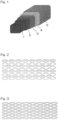
- an example of a stent of the present invention comprises: a core structure 1 comprising a magnesium alloy (Mg alloy); a first corrosion resistant layer 2 formed on an entire surface of the core structure 1 and comprising magnesium fluoride (MgF 2 ) [the first corrosion resistant layer contains Mg(OH) 2 etc.
- Mg alloy magnesium alloy
- MgF 2 magnesium fluoride
- biodegradable resin layer 4 may contain a medicine or a drug, instead of providing a biodegradable resin layer 5 containing a medicine).
- an element for selecting a composition of the magnesium alloy for constituting the core structure having a biodegradability and excellent deformability an element for forming the first corrosion resistant layer containing MgF 2 as a main component over the entire surface of the core structure so as to control corrosion of the core structure comprising the selected magnesium alloy; an element for forming the second corrosion resistant layer comprising a parylene on the first corrosion resistant layer; and an element for forming a biodegradable resin layer coated on the core structure and containing a medicine or a drug.
- the core structure of the stent according to the present invention comprises a bioabsorbable magnesium alloy.
- the core structure of the stent comprises a magnesium alloy that contains 90 wt% or more of magnesium (Mg) as a main component; and zinc (Zn), zirconium (Zr), and manganese (Mn) as accessary components and is free of a rare earth element(s) and aluminum (Al).
- Mg magnesium
- Zr zirconium
- Mn manganese
- the content of Mg may more suitably be 93 wt% or more and further suitably be 95 wt% or more.
- the magnesium alloy does not contain a rare earth element(s).
- the rare earth element may refer to at least one selected from the group consisting of scandium (Sc), yttrium (Y), dysprosium (Dy), samarium (Sm), cerium (Ce), gadolinium (Gd), lantern (La), and neodymium (Nd). Absence of the rare earth element(s) and aluminum can prevent a potential harmful effect to the human body.
- the magnesium alloy contains 0.95 to 2.0 wt% of Zn, 0.05 to 0.80 wt% of Zr, and 0.05 to 0.40 wt% of Mn as accessory components.
- Zn is added in order to enhance the strength and ductility of the alloy by forming a solid solution with Mg.
- a too small amount of Zn may be not preferable because of insufficient desired effect.
- a too large amount of Zn may be not preferable because such an amount may exceed a solid solubility limit of Zn in Mg that Zn-rich precipitates are formed, resulting in reduced corrosion resistance.
- Zr hardly forms a solid solution in Mg, and forms fine precipitates, providing an effect of preventing the alloy from having coarse crystal grains. Where a too small amount of Zr is added, the effect of addition cannot be obtained. Where a too large amount of Zr is added, the amount of precipitates increases and the processability decreases, which is not preferable.
- Mn allows alloy structure (crystal structure) to be extremely fine so as to have improved corrosion resistance. Where the content of Mn is too small, the desired effect cannot be obtained. Where the content of Mn is too large, plastic working of the alloy tends to decrease.
- Calcium (Ca) may further be added to the above accessary components in a proportion of 0.05 wt% or more and less than 0.20 wt%. Since Ca is expected to have the effect of improving the corrosion resistance while maintaining the strength of the magnesium alloy, Ca may be added depending on needs. Where the content of Ca is too small, the effect of addition cannot be obtained. A too large content of Ca is not preferable because of a possibility of precipitate formation, making it difficult to obtain a single-phase complete solid solution.
- the magnesium alloy may contain unavoidable impurities selected from the group consisting of iron (Fe), nickel (Ni), cobalt (Co), and copper (Cu), the content of each of the unavoidable impurities preferably being lower than 10 ppm, and the total content of the unavoidable impurities being 30 ppm or lower.
- the contents of the unavoidable impurities are preferably controlled. Since Fe, Ni, Co, and Cu promote corrosion of the magnesium alloy, the content of each of the unavoidable impurities may be lower than 10 ppm and further preferably 5 ppm or lower. The total content of the unavoidable impurities is 30 ppm or lower and further preferably lower than 10 ppm. The contents of the unavoidable impurities can be determined by, for example, ICP atomic emission spectroscopy.
- the magnesium alloy may be produced by throwing ground metals or alloys of Mg, Zn, Zr, Mn and, if needed, Ca into a crucible, melting the ground metals and/or alloys in the crucible at a temperature from 650 to 800 °C, and casting the molten alloy. Where necessary, the cast alloy may be subjected to solution heat treatment.
- the ground metals do not contain the rare earth element(s) and aluminum. It is possible to suppress the amounts of Fe, Ni, and Cu in the impurities by the use of high purity ground metals. Fe, Ni, and Co in the impurities of the molten alloy may be removed by de-ironing treatment. In addition, or alternatively, it is possible to use ground metals produced by distillation refining.
- the magnesium alloy used in the present invention can have a fine and uniform structure in terms of a grain size distribution with an average crystal grain size from 1.0 to 3.0 ⁇ m (preferably from 1.0 to 2.0 ⁇ m) and a standard deviation of 0.7 or lower (preferably from 0.5 to 0.7), thanks to the composition as described above and controlled production method.
- Fine precipitates containing Zr may each have a particle diameter smaller than 500 nm (preferably smaller than 100 nm).
- a matrix phase excluding the Zr-precipitates may preferably be an all-proportional solid solution of the Mg-Zn-Mn ternary alloy.
- the magnesium alloy used in the present invention preferably has mechanical properties such as a tensile strength from 230 to 380 MPa (preferably from 250 to 300 MPa), a proof strength from 145 to 220 MPa, and a fracture elongation from 15 to 50% (preferably from 25 to 40%) when measured in accordance with JIS Z2241.
- the magnesium alloy further preferably has a tensile strength exceeding 280 MPa and a fracture elongation exceeding 30%.
- the ingots prepared in the above-described manner are subjected to hot extrusion to produce a magnesium alloy tubular material, and the thus-obtained magnesium alloy tubular material is laser-processed to form a stent scaffold (core structure).
- the stent of the present invention may be formed into various scaffold shapes including conventional ones.
- the stent may have the scaffold shape shown in Fig. 2 or Fig. 3 .
- a preferable method of producing a core structure having an arbitrary size includes: connecting a laser-processed stent scaffold and a metal plate to an anode and a cathode, respectively, via a direct current (DC) power source in an electrolytic solution; and applying a voltage to them so as to electropolish the stent scaffold on the side of the anode.
- DC direct current
- the mirror-finished core structure by electropolishing is subjected to fluorination.
- the condition of fluorination is not particularly limited.
- the core structure may be immersed in a treatment liquid such as an aqueous solution of hydrofluoric acid (HF) to carry out fluorination. It is preferable to shake the core structure at a speed of, for example, 50 to 200 rpm (preferably 80 to 150 rpm) during immersion. Then, the core structure on the surface of which the MgF 2 layer is formed is taken out and sufficiently washed with a cleaning solution (for example, acetone and water).
- the core structure is, for example, washed by ultrasonic cleaning. Where the core structure is dried after cleaning, the core structure is preferably dried at a temperature from 50 to 60°C under reduced pressure for 24 hours or longer.
- the first corrosion resistant layer of the stent according to the present invention contains magnesium fluoride as a main component.
- the first corrosion resistant layer may contain 90% or more of MgF 2 as a main component.
- the first corrosion resistant layer may also contain oxides and hydroxides such as MgO and Mg(OH) 2 as accessary components. It should be noted that the first corrosion resistant layer may also contain oxides and hydroxides of metals other than magnesium which constitute the stent.
- the first corrosion resistant layer of the stent according to the present invention suitably has a layer thickness of 0.5 ⁇ m or larger in order to exhibit corrosion resistance and a layer thickness of 1.5 ⁇ m or smaller in order to exhibit deformation followability. A layer thickness exceeding 1.5 ⁇ m may be avoided because too high corrosion resistance impairs bioabsorbability.
- a thin second corrosion resistant layer comprising a parylene and having a thickness from 0.05 to 1 ⁇ m (preferably from 0.08 to 0.8 ⁇ m) is formed on the first corrosion resistant layer so as to remarkably improve corrosion resistance of the magnesium alloy without impairing bioabsorbability.
- the second corrosion resistant layer is too thin, the anticorrosion effect tends to be insufficient; where the second corrosion resistant layer is too thick, bioabsorbability tends to be impaired.
- Parylene collectively refers to paraxylylenes and derivatives thereof.
- Examples of parylenes may include: a parylene N having no functional group in the aromatic ring [the following formula (1)], a parylene C in which one of the hydrogens in the aromatic ring is substituted with chlorine [the following formula (2)], a parylene M in which one of the hydrogens in the aromatic ring is substituted with a methyl group [the following formula (3)], a parylene F in which one of the methylene groups of the parylene M is fluorinated [the following formula (4)], a parylene D in which hydrogens at the 2,5-positions of the aromatic ring of the parylene N are replaced by chlorine [the following formula (5)], and a parylene HT in which both the methylene groups of the parylene N are fluorinated [the following formula (6)].
- These parylenes are commercially available; for example, a parylene N and a parylene C can be obtained from Dai San
- the second corrosion resistant layer comprising a parylene is typically formed by CVD process.
- the CVD process of parylene itself is known, and the process includes: in a device system having a vaporization furnace, a decomposition furnace and a vapor deposition chamber, (a) subjecting the device system to be vacuumed to have a pressure inside the device system of approximately 1 to 4 Pa using a vacuum pump; (b) heating dimers in the vaporization furnace to a temperature of 100 to 180°C so as to sublimate the dimers; (c) passing the dimers through the decomposition furnace pipe at 650 to 700°C so as to convert the dimers into monomers; and (d) polymerizing the monomers to a parylene in the vapor deposition chamber to be deposited on the surface of a first corrosion resistant layer at a predetermined thickness so as to form a second corrosion resistant layer.
- a cover layer comprising a biodegradable polymer and an intimal thickening inhibitor may be formed on the entirety or a part of a surface of the second corrosion resistant layer.
- the biodegradable polymers may include polyesters, such as a poly-L-lactic acid (PLLA), a poly-D,L-lactic acid (PDLLA), a poly(lactic acid-glycolic acid) (PLGA), a polyglycolic acid (PGA), a polycaprolactone (PCL), a polylactic acid- ⁇ -caprolactone (PLCL), a poly(glycolic acid- ⁇ -caprolactone) (PGCL), a poly-p-dioxanone, a poly(glycolic acid-trimethylene carbonate), a poly- ⁇ -hydroxybutyric acid, and others.
- PLLA poly-L-lactic acid
- PLLA poly(lactic acid-glycolic acid)
- PGA polyglycolic acid
- PCL polycaprolactone
- intimal thickening inhibitor examples include sirolimus, everolimus, biolimus A9, zotarolimus, paclitaxel, etc.
- the stent on which the corrosion resistant layer having the smooth surface is formed as described above can have a significantly suppressed temporal reduction of a radial force in a simulated plasma solution (EMEM + 10% FBS) at 37°C under 5% CO 2 atmosphere as well as in pig coronary arteries, when compared with a stent that does not fall within the scope of the present invention or a stent without a corrosion resistant layer (core structure alone) (see Examples and Comparative Examples below).
- EMEM + 10% FBS simulated plasma solution
- High purity ground metals of Mg, Zn, Mn, and Zr were prepared as initial materials. Each of the metals was weighed so as to have a component concentration as described below and was thrown into a crucible. Then, at 730°C the metals were molten with stirring, and a thus-obtained melt was cast to form ingots.
- the initial materials used did not contain rare earth elements or aluminum even as unavoidable impurities.
- the ingots had the following component concentrations (wt%): Mg balance with Zn 1.5%, Mn 0.4%, and Zr 0.4%.
- the ingots did not contain aluminum and rare earth elements.
- the ingots contained Fe, Ni, Co and Cu as unavoidable impurities at the following concentrations: Fe 5 ppm, Ni 5 ppm, Co ND: undetectable (below detection limit), and Cu 1 ppm.
- the magnesium alloy ingot was subjected to extrusion processing to produce a thin tube having a thickness of 150 ⁇ m (outer diameter 1.8 mm / inner diameter 1.5 mm), and the thin tube was laser-processed into the shape shown in Fig. 2 to obtain a stent scaffold.
- the surface of the thus-obtained stent scaffold was cleaned with an acidic solution to remove oxides on the surface. Then, the stent scaffold was immersed in an electrolytic solution. The stent scaffold was connected to an anode side and a metal plate was connected to a cathode side, via a DC power source. A voltage was then applied such that the stent scaffold on the anode side was mirror-polished until the stent scaffold had a thickness of 100 ⁇ m (outer diameter 1.75 mm / inner diameter 1.55 mm) so as to make the stent surface smooth. During voltage application, the electrolytic solution was stirred with keeping a constant temperature in order to stabilize a viscous liquid layer. Also, in order to suppress bubbles generated on the cathode, the voltage was intermittently applied as appropriate. It should be noted that adherence of bubbles released from the cathode to the stent scaffold may cause poor surface precision.
- a stent sample later-described in each of the Examples and Comparative Examples was prepared from the stent scaffold.
- the stent sample was positioned (crimped) on a balloon attached to a distal end portion of a balloon catheter such that the stent sample had an outer diameter of 1.2 mm.
- a layer thickness of a first corrosion resistant layer of a stent sample was measured in the following way.
- the stent sample on which the first corrosion resistant layer was formed as described in the Examples and Comparative Examples was subjected to gold sputtering and then embedded into an epoxy resin. Thereafter, the layer thickness was measured on a cut surface of the stent sample using an SEM-EDX.
- a layer thickness of a second corrosion resistant layer was measured using an ellipsometer or a spectrographic film thickness meter, from a surface of a stent sample having the second corrosion resistant layer as described in the Examples and Comparative Examples.
- a surface having excellent corrosion resistance and deformation followability is capable of delaying decrease in mechanical strength associated with accelerated corrosion of a core structure in the blood vessels.
- corrosion resistance and deformation followability can be evaluated by determining a weight change and a radial force residual ratio of the core structure in a simulated plasma solution (EMEM + 10% FBS) at 37°C under 5% CO 2 atmosphere.
- a stent sample crimped at a balloon catheter was immersed in a 37°C simulated plasma solution (EMEM + 10% FBS) for 2 minutes, then was uniformly expanded to have an inner diameter of 3 mm ( Fig. 5 ), and was shaken at 100 rpm with keeping immersion at 37°C under 5% CO 2 atmosphere. It means that the stent at this stage was exposed to plastic elastic deformation (physical change) by crimping (reducing diameter) to a balloon catheter and stenting (expanding diameter) ( Fig. 4 ). The sample was taken out after 28 days of immersion, and the radial force of the sample was measured.
- EMEM + 10% FBS a 37°C simulated plasma solution
- a chromic acid solution to completely remove corrosion products such as magnesium hydroxide, etc.
- RX550/650 produced by Machine Solutions Inc.
- Mg ion measurement a magnesium B-test Wako (produced by Fujifilm Wako Pure Chemical Industries, Ltd.) was used
- the stent surface was observed using a scanning electron microscope (SEM) before expansion, after expansion to an inner diameter of 3 mm, and after 28 days of immersion in the simulated plasma solution.
- SEM scanning electron microscope
- Example 2 immersion Comparative Example 2 As for each of the samples of Example 2 immersion Comparative Example 2, the stent cross section was observed using an optical interference tomographic meter (OCT) immediately after implantation in pig coronary artery and at 28 days after implantation in pig coronary artery.
- OCT optical interference tomographic meter
- a core structure comprising the above-described stent scaffold was immersed in a 27 M hydrofluoric-acid aqueous solution (2 mL) and reciprocally moved at a rate of 100 rpm. Then, the stent was taken out after 24 hours, and subjected to ultrasonic cleaning sufficiently with water and acetone followed by drying the core structure for 24 hours at 60°C under vacuum to prepare a core structure on which a first corrosion resistant layer (thickness: 1 ⁇ m) was formed.
- a parylene C layer having a thickness of 100 nm was formed on this structure by CVD process so as to form a second corrosion resistant layer.
- a first cover layer containing 400 ⁇ g of a first polymer PCL was spray-coated, and then a second cover layer containing 150 ⁇ g of a second polymer PDLLA and 100 ⁇ g of sirolimus was spray-coated so as to obtain a stent sample shown in Fig. 1 .
- a core structure comprising the above-described stent scaffold was immersed in a 27 M hydrofluoric-acid aqueous solution (2 mL) and reciprocally moved at a rate of 100 rpm. Then, the stent was taken out after 24 hours, and subjected to ultrasonic cleaning sufficiently with water and acetone followed by drying the core structure for 24 hours at 60°C under vacuum to prepare a core structure on which a first corrosion resistant layer (thickness: 1 ⁇ m) was formed.
- a parylene C layer having a thickness of 500 nm was formed on this structure by CVD process so as to form a second corrosion resistant layer.
- a first cover layer containing 400 ⁇ g of a first polymer PCL was spray-coated, and then a second cover layer containing 150 ⁇ g of a second polymer PDLLA and 100 ⁇ g of sirolimus was spray-coated so as to obtain a stent sample shown in Fig. 1 .
- a (non-fluorinated) core structure having an above-described stent scaffold was prepared as a stent sample.
- a core structure comprising the above-described stent scaffold was immersed in a 27 M hydrofluoric-acid aqueous solution (2 mL) and reciprocally moved at a rate of 100 rpm. Then, the stent was taken out after 24 hours, and subjected to ultrasonic cleaning sufficiently with water and acetone followed by drying the core structure for 24 hours at 60°C under vacuum to prepare a core structure on which a first corrosion resistant layer (thickness: 1 ⁇ m) was formed.
- a first cover layer containing 400 ⁇ g of a first polymer PCL was spray-coated, and then a second cover layer containing 150 ⁇ g of a second polymer PDLLA and 100 ⁇ g of sirolimus was spray-coated so as to obtain a stent sample shown in Fig. 7 .
- a parylene C layer having a thickness of 500 nm was formed by CVD process so as to form a second corrosion resistant layer.
- a first cover layer containing 400 ⁇ g of a first polymer PCL was spray-coated, and then a second cover layer containing 150 ⁇ g of a second polymer PDLLA and 100 ⁇ g of sirolimus was spray-coated so as to obtain a stent sample shown in Fig. 8 .
- Each of the samples before immersion had a weight of 5.92 ⁇ 0.32 g, and each of the core structures before immersion had a radial force of 63.12 ⁇ 5.36 N/mm.
- Ex. 1 100 99.1 ⁇ 1.3
- Fig. 1 Ex. 2 100 99.3 ⁇ 1.2
- Ex. 1 100 79.5 ⁇ 2.9 Fig. 6 Com.
- Ex. 1
- Example 1 The samples having the constituting elements according to the present invention (Example 1, Example 2) had smaller changes in weight and radial force when compared with those of the sample without a corrosion resistant layer 2 (Comparative Example 2) and the sample without a corrosion resistant layer 1 (Comparative Example 3). Thus, it was indicated that the double layer structure of the first corrosion resistant layer and the second corrosion resistant layer provided an excellent anticorrosion effect. In contrast, the sample having none of the corrosion resistant layers (Comparative Example 1) showed considerable decrease in radial force associated with corrosion.
- [Table 3] Decomposition Behavior of Stent Samples Before and After Immersion (Mg Ion Elution Rate [%]) After 7 days of immersion After 14 days of immersion After 21 days of immersion After 28 days of immersion (Remark)
- Ex. 2 0.1 ⁇ 0.1 0.1 0.1 0.1 0.1 0.1 0.5 ⁇ 0.2 1.1 ⁇ 0.2 1.2 ⁇ 0.4
- Com. Ex.
- Ex. 3 0.9 ⁇ 2.5 3.5 ⁇ 1.9 6.6 ⁇ 2.8 8.9 ⁇ 3.1 Fig. 8
- Example 2 The samples having the constituting elements according to the present invention (Example 2) had an extremely smaller amount of Mg ions eluted over time when compared with those of the sample without a corrosion resistant layer 2 (Comparative Example 2) and the sample without a corrosion resistant layer 1 (Comparative Example 3). Thus, it was confirmed that provision of both of the first corrosion resistant layer and the second corrosion resistant layer advantageously provided a synergetic effect. That is, a desired anticorrosive effect that makes a bioabsorbable stent practically applicable cannot be obtained by providing only one of the corrosion resistant layer 2 and the corrosion resistant layer 3.
- Fig. 9 to Fig. 14 show results of SEM observation of each stent surface of the samples of Example 2 and Comparative Example 2 before expansion, after expansion, and after 28 days of immersion in the simulated plasma solution.
- Fig. 9 to Fig. 11 show the stent surfaces of the samples of Example 2 before expansion ( Fig. 9 ), after expansion ( Fig. 10 ), and after 28 days of immersion in the simulated plasma solution ( Fig. 11 ).
- Fig. 12 to Fig. 14 show the stent surfaces of the samples of the Comparative Example 2 before expansion ( Fig. 12 ), after expansion ( Fig. 13 ), and after 28 days of immersion in the simulated plasma solution ( Fig. 14 ).
- Example 2 As for the respective samples of Example 2 and Comparative Example 2, OCT observation images of cross sections of pig coronary arteries immediately after stent implantation and at 28 days after stent implantation are shown in Fig. 15 (Example 2 immediately after implantation), Fig. 16 (Example 2 at 28 days after implantation), Fig. 17 (Comparative Example 2 immediately after implantation), Fig. 18 (Comparative Example 2 at 28 days after implantation).
- Recoil values of the respective stent samples of Example 2 and Comparative Example 2 were determined at 28 days after implantation in pig coronary arteries.
- Table 4 shows calculation results of the recoil values at 28 days after implantation relative to stent inner areas before implantation.
- Recoil Values of Stents at 28 Days After Implantation [%] 28 days after implantation Ex. 2 13 ⁇ 4 Com. Ex. 2 25 ⁇ 5
- Example 2 The samples having the constituting elements according to the present invention (Example 2) had significantly smaller recoil values when compared with those of the samples without the scope of the present invention (Comparative Example 2). The obtained recoil values corresponded to the other results.
- the present invention can provide a stent comprising a core structure comprising a magnesium alloy free of a rare earth element and aluminum and highly safe to the living body and, as well as a first corrosion resistant layer and a second corrosion resistant layer that effectively delay decrease in mechanical strength associated with accelerated corrosion of the core structure. Therefore, the present invention contributes to development of medical technology and thus has remarkable industrial applicability.
Landscapes
- Health & Medical Sciences (AREA)
- Life Sciences & Earth Sciences (AREA)
- Vascular Medicine (AREA)
- Heart & Thoracic Surgery (AREA)
- Animal Behavior & Ethology (AREA)
- General Health & Medical Sciences (AREA)
- Public Health (AREA)
- Veterinary Medicine (AREA)
- Surgery (AREA)
- Epidemiology (AREA)
- Chemical & Material Sciences (AREA)
- Inorganic Chemistry (AREA)
- Engineering & Computer Science (AREA)
- Biomedical Technology (AREA)
- Medicinal Chemistry (AREA)
- Molecular Biology (AREA)
- Chemical Kinetics & Catalysis (AREA)
- Polymers & Plastics (AREA)
- Organic Chemistry (AREA)
- Cardiology (AREA)
- Oral & Maxillofacial Surgery (AREA)
- Transplantation (AREA)
- Materials For Medical Uses (AREA)
- Media Introduction/Drainage Providing Device (AREA)
Claims (9)
- Bioabsorbierbarer Stent, umfassend:eine Kernstruktur, umfassend eine Magnesiumlegierung, die 90 Gewichts-% oder mehr Magnesium als Hauptkomponente und 0,95 bis 2,00 Gewichts-% Zink, 0,05 bis 0,80 Gewichts-% Zirkonium und 0,05 bis 0,40 Gewichts-% Mangan als Nebenkomponenten enthält, wobei die Magnesiumlegierung frei von einem Seltenerdelement und Aluminium ist; wobei in der Magnesiumlegierung unvermeidbare Verunreinigungen, ausgewählt aus der Gruppe, bestehend aus Fe, Ni, Co und Cu, in einem Gesamtgehalt von 30 ppm oder weniger enthalten sind,wobei eine erste korrosionsbeständige Schicht auf der Kernstruktur der Magnesiumlegierung gebildet ist und Magnesiumfluorid als Hauptkomponente enthält; undeine zweite korrosionsbeständige Schicht auf der ersten korrosionsbeständigen Schicht gebildet ist und ein Parylen umfasst.
- Bioabsorbierbarer Stent nach Anspruch 1, wobei die erste korrosionsbeständige Schicht eine Schichtstärke von 0,5 bis 1,5 µm aufweist.
- Bioabsorbierbarer Stent nach Anspruch 1 oder Anspruch 2, wobei die Parylenschicht, die die zweite korrosionsbeständige Schicht darstellt, ein Parylen N (chemische Formel 1 unten), ein Parylen C (chemische Formel 2 unten), ein Parylen M (chemische Formel 3 unten), ein Parylen F (chemische Formel 4 unten), ein Parylen D (chemische Formel 5 unten) oder ein Parylen HT (chemische Formel 6 unten) umfasst.


- Bioabsorbierbarer Stent nach einem der Ansprüche 1 bis 3, wobei die zweite korrosionsbeständige Schicht eine Schichtstärke von 0,05 bis 1 µm aufweist.
- Bioabsorbierbarer Stent nach einem der Ansprüche 1 bis 4, wobei auf mindestens einem Teil der Oberfläche der zweiten korrosionsbeständigen Schicht eine biologisch abbaubare Polymerschicht gebildet ist.
- Bioabsorbierbarer Stent nach Anspruch 5, wobei das biologisch abbaubare Polymer ein aliphatischer Polyester ist.
- Bioabsorbierbarer Stent nach Anspruch 5 oder 6, wobei die biologisch abbaubare Polymerschicht einen Intimaverdickungshemmer enthält.
- Bioabsorbierbarer Stent nach Anspruch 7, wobei der Hemmer ein Limus-Arzneimittel ist.
- Verfahren zum Herstellen eines bioabsorbierbaren Stents, der eine Kernstruktur beinhaltet, umfassend eine Magnesiumlegierung, die 90 Gewichts-% oder mehr Magnesium als Hauptkomponente und 0,95 bis 2,00 Gewichts-% Zink, 0,05 bis 0,80 Gewichts-% Zirkonium und 0,05 bis 0,40 Gewichts-% Mangan als Nebenkomponenten enthält, wobei die Magnesiumlegierung frei von einem Seltenerdelement und Aluminium ist; wobei in der Magnesiumlegierung unvermeidbare Verunreinigungen, ausgewählt aus der Gruppe, bestehend aus Fe, Ni, Co und Cu, in einem Gesamtgehalt von 30 ppm oder weniger enthalten sind, das Verfahren umfassend:Herstellen der Kernstruktur, umfassend die Magnesiumlegierung;Elektropolieren der Kernstruktur und Durchführen von Fluorierung an einer Oberfläche der elektropolierten Kernstruktur, um eine erste korrosionsbeständige Schicht zu bilden, die Magnesiumfluorid als Hauptkomponente enthält; undAufdampfen eines Paraxylylenharzes auf die erste korrosionsbeständige Schicht, um eine zweite korrosionsbeständige Schicht, umfassend ein Parylen, zu bilden.
Applications Claiming Priority (3)
| Application Number | Priority Date | Filing Date | Title |
|---|---|---|---|
| JP2018054300 | 2018-03-22 | ||
| JP2018144220 | 2018-07-31 | ||
| PCT/JP2019/011667 WO2019182003A1 (ja) | 2018-03-22 | 2019-03-20 | 生体吸収性ステント |
Publications (3)
| Publication Number | Publication Date |
|---|---|
| EP3769797A1 EP3769797A1 (de) | 2021-01-27 |
| EP3769797A4 EP3769797A4 (de) | 2021-12-15 |
| EP3769797B1 true EP3769797B1 (de) | 2025-05-28 |
Family
ID=67986531
Family Applications (1)
| Application Number | Title | Priority Date | Filing Date |
|---|---|---|---|
| EP19771463.7A Active EP3769797B1 (de) | 2018-03-22 | 2019-03-20 | Bioresorbierbarer stent |
Country Status (6)
| Country | Link |
|---|---|
| US (1) | US12109333B2 (de) |
| EP (1) | EP3769797B1 (de) |
| JP (2) | JP6678982B2 (de) |
| CN (2) | CN114177366A (de) |
| CA (1) | CA3094504A1 (de) |
| WO (1) | WO2019182003A1 (de) |
Families Citing this family (12)
| Publication number | Priority date | Publication date | Assignee | Title |
|---|---|---|---|---|
| CN110234366B (zh) | 2017-01-30 | 2021-11-02 | 株式会社日本医疗机器技研 | 高功能生物可吸收支架 |
| CA3094504A1 (en) | 2018-03-22 | 2019-09-26 | Japan Medical Device Technology Co., Ltd. | Bioabsorbable stent |
| CA3104447C (en) | 2018-07-09 | 2022-02-15 | Japan Medical Device Technology Co., Ltd. | Magnesium alloy |
| WO2020158761A1 (ja) * | 2019-01-30 | 2020-08-06 | 株式会社日本医療機器技研 | 生体吸収性ステント |
| CA3134811A1 (en) | 2019-03-28 | 2020-10-01 | Japan Medical Device Technology Co., Ltd. | Surface-modified magnesium alloy |
| EP3950989A4 (de) | 2019-03-28 | 2023-04-12 | JAPAN Medical Device Technology Co., Ltd. | Implantat für nichtluminalen bereich |
| CN110468319B (zh) * | 2019-08-13 | 2021-05-18 | 中国兵器科学研究院宁波分院 | 一种Mg-Y-Nd-(La+Ce)-Zr生物可降解镁合金及其制备方法 |
| DE202021100450U1 (de) * | 2021-01-29 | 2021-02-18 | Biotronik Ag | Schnell resorbierbares intravaskuläres Implantat |
| CN113694262A (zh) * | 2021-08-26 | 2021-11-26 | 苏州脉悦医疗科技有限公司 | 一种生物可吸收的镁合金支架及其制备方法 |
| CN114767950B (zh) * | 2022-04-26 | 2023-06-20 | 大连理工大学 | 一种镁合金支架用的防腐与载药复合涂层及其制备方法 |
| CN115531606B (zh) * | 2022-09-30 | 2024-03-26 | 珠海奥华复维医疗技术有限公司 | 一种梯度降解的网状植入物、其制备方法及其用途 |
| CN119656394B (zh) * | 2024-12-20 | 2025-09-09 | 河南省科学院材料研究所 | 一种带有纳米斥水层和生物活性涂层的镁合金血管支架材料及其制备方法 |
Family Cites Families (31)
| Publication number | Priority date | Publication date | Assignee | Title |
|---|---|---|---|---|
| GB851871A (en) | 1957-10-25 | 1960-10-19 | British Thomson Houston Co Ltd | Improved magnesium alloys |
| GB9023270D0 (en) | 1990-10-25 | 1990-12-05 | Castex Prod | Magnesium manganese alloy |
| JP3518704B2 (ja) | 1995-06-22 | 2004-04-12 | 株式会社ニコン | 接眼レンズ |
| JP2005531391A (ja) * | 2002-06-27 | 2005-10-20 | 微創医療器械(上海)有限公司 | 薬剤放出ステント |
| JP2004183062A (ja) | 2002-12-04 | 2004-07-02 | Sumitomo Denko Steel Wire Kk | マグネシウム基合金線及びその製造方法 |
| EP2146209B1 (de) * | 2005-04-06 | 2011-11-16 | University of Antwerp | Neurodegenerative Marker für Alzheimer-Krankheit |
| WO2007108450A1 (ja) | 2006-03-20 | 2007-09-27 | National Institute For Materials Science | 医療用生分解性マグネシウム材 |
| US20100145436A1 (en) * | 2006-09-18 | 2010-06-10 | Boston Scientific Scimed, Inc. | Bio-erodible Stent |
| CN101468216A (zh) * | 2007-12-26 | 2009-07-01 | 中国科学院金属研究所 | 一种带药可降解镁合金心血管支架及其制备方法 |
| JP5467294B2 (ja) | 2008-06-05 | 2014-04-09 | 独立行政法人産業技術総合研究所 | 易成形性マグネシウム合金板材及びその作製方法 |
| CN101629260A (zh) | 2008-07-18 | 2010-01-20 | 中国科学院金属研究所 | 医用可吸收Mg-Zn-Mn-Ca镁合金 |
| US20100057188A1 (en) | 2008-08-28 | 2010-03-04 | Boston Scientific Scimed, Inc. | Endoprostheses with porous regions and non-polymeric coating |
| DE102008054400A1 (de) | 2008-12-09 | 2010-06-10 | Biotronik Vi Patent Ag | Implantat und Verfahren zur Herstellung desselben |
| DE102008054920A1 (de) * | 2008-12-18 | 2010-07-01 | Biotronik Vi Patent Ag | Implantat sowie Verfahren zur Herstellung einer Schichtstruktur |
| US9254350B2 (en) * | 2009-04-10 | 2016-02-09 | Medtronic Vascular, Inc. | Implantable medical devices having bioabsorbable primer polymer coatings |
| US8382823B2 (en) * | 2009-05-28 | 2013-02-26 | Snu R&Db Foundation | Biodegradable stent and method for manufacturing the same |
| JP5720926B2 (ja) | 2010-10-12 | 2015-05-20 | 住友電気工業株式会社 | マグネシウム合金の線状体及びボルト、ナット並びにワッシャー |
| US20130090741A1 (en) | 2011-10-07 | 2013-04-11 | Medtronic Vascular, Inc. | Magnesium Alloys for Bioabsorbable Stent |
| US9504554B2 (en) | 2013-01-16 | 2016-11-29 | Biotronik Ag | Microstructured absorbable implant |
| US9155637B2 (en) | 2013-03-13 | 2015-10-13 | Medtronic Vascular, Inc. | Bioabsorbable stent with hydrothermal conversion film and coating |
| JP6502315B2 (ja) | 2013-03-14 | 2019-04-17 | デピュイ・シンセス・プロダクツ・インコーポレイテッド | 分解速度が調整可能なマグネシウム合金 |
| CN104046867B (zh) | 2014-06-26 | 2017-01-25 | 宝山钢铁股份有限公司 | 一种高塑性导热镁合金及其制备方法 |
| CN107106736B (zh) | 2014-11-06 | 2020-08-04 | 美敦力瓦斯科尔勒公司 | 用于生物可吸收性支架的保护的镁合金 |
| CN104498790B (zh) | 2014-12-01 | 2017-04-26 | 中国兵器科学研究院宁波分院 | 一种可降解镁合金生物植入材料及其制备方法 |
| CN104630587A (zh) | 2015-02-28 | 2015-05-20 | 天津理工大学 | 一种骨折内固定用可降解镁合金板、棒材及其制备方法 |
| CN105256213A (zh) * | 2015-12-01 | 2016-01-20 | 天津东义镁制品股份有限公司 | 生物医用Mg-Zn-Zr-Mn镁合金及其制备方法 |
| EP3342433A1 (de) * | 2016-12-27 | 2018-07-04 | MeKo Laserstrahl-Materialbearbeitungen e.K. | Stent aus einer biologisch abbaubaren magnesiumlegierung mit einer magnesiumfluorid-beschichtung und einer organischen beschichtung |
| CN110234366B (zh) | 2017-01-30 | 2021-11-02 | 株式会社日本医疗机器技研 | 高功能生物可吸收支架 |
| US10201639B2 (en) * | 2017-05-01 | 2019-02-12 | 480 Biomedical, Inc. | Drug-eluting medical implants |
| CN107385419B (zh) * | 2017-06-28 | 2019-02-15 | 河南工业大学 | 一种提高医用镁合金表面耐腐蚀及亲水性能的涂层及其制备方法 |
| CA3094504A1 (en) | 2018-03-22 | 2019-09-26 | Japan Medical Device Technology Co., Ltd. | Bioabsorbable stent |
-
2019
- 2019-03-20 CA CA3094504A patent/CA3094504A1/en active Pending
- 2019-03-20 WO PCT/JP2019/011667 patent/WO2019182003A1/ja not_active Ceased
- 2019-03-20 JP JP2019552935A patent/JP6678982B2/ja active Active
- 2019-03-20 CN CN202111300689.6A patent/CN114177366A/zh active Pending
- 2019-03-20 CN CN201980005605.0A patent/CN111315420A/zh active Pending
- 2019-03-20 EP EP19771463.7A patent/EP3769797B1/de active Active
-
2020
- 2020-03-04 JP JP2020036796A patent/JP7298917B2/ja active Active
- 2020-09-17 US US17/024,262 patent/US12109333B2/en active Active
Also Published As
| Publication number | Publication date |
|---|---|
| CA3094504A1 (en) | 2019-09-26 |
| CN111315420A (zh) | 2020-06-19 |
| US12109333B2 (en) | 2024-10-08 |
| JPWO2019182003A1 (ja) | 2020-04-30 |
| WO2019182003A1 (ja) | 2019-09-26 |
| EP3769797A4 (de) | 2021-12-15 |
| EP3769797A1 (de) | 2021-01-27 |
| JP7298917B2 (ja) | 2023-06-27 |
| JP2020093117A (ja) | 2020-06-18 |
| US20210001013A1 (en) | 2021-01-07 |
| JP6678982B2 (ja) | 2020-04-15 |
| CN114177366A (zh) | 2022-03-15 |
Similar Documents
| Publication | Publication Date | Title |
|---|---|---|
| US12109333B2 (en) | Bioabsorbable stent | |
| EP3574928B1 (de) | Hochleistungsfähiger bioresorbierbarer stent | |
| Hanawa | Materials for metallic stents | |
| CA2758255C (en) | Bioerodible, implantable medical devices incorporating supersaturated magnesium alloys | |
| US20120215301A1 (en) | Biodegradable implantable medical devices formed from super - pure magnesium-based material | |
| US10960110B2 (en) | Iron-based biodegradable metals for implantable medical devices | |
| US20210353836A1 (en) | Bioabsorbable stent | |
| US9259516B2 (en) | Implant and method for manufacturing | |
| JP7428698B2 (ja) | 非管腔領域用インプラント | |
| US12264395B2 (en) | Surface-modified magnesium alloy | |
| WO2011119603A1 (en) | Bioerodible medical implants |
Legal Events
| Date | Code | Title | Description |
|---|---|---|---|
| STAA | Information on the status of an ep patent application or granted ep patent |
Free format text: STATUS: THE INTERNATIONAL PUBLICATION HAS BEEN MADE |
|
| PUAI | Public reference made under article 153(3) epc to a published international application that has entered the european phase |
Free format text: ORIGINAL CODE: 0009012 |
|
| STAA | Information on the status of an ep patent application or granted ep patent |
Free format text: STATUS: REQUEST FOR EXAMINATION WAS MADE |
|
| 17P | Request for examination filed |
Effective date: 20200928 |
|
| AK | Designated contracting states |
Kind code of ref document: A1 Designated state(s): AL AT BE BG CH CY CZ DE DK EE ES FI FR GB GR HR HU IE IS IT LI LT LU LV MC MK MT NL NO PL PT RO RS SE SI SK SM TR |
|
| AX | Request for extension of the european patent |
Extension state: BA ME |
|
| DAV | Request for validation of the european patent (deleted) | ||
| DAX | Request for extension of the european patent (deleted) | ||
| A4 | Supplementary search report drawn up and despatched |
Effective date: 20211117 |
|
| RIC1 | Information provided on ipc code assigned before grant |
Ipc: A61L 31/14 20060101ALI20211111BHEP Ipc: A61L 31/12 20060101ALI20211111BHEP Ipc: A61L 31/10 20060101ALI20211111BHEP Ipc: A61L 31/08 20060101ALI20211111BHEP Ipc: A61L 31/04 20060101ALI20211111BHEP Ipc: A61F 2/915 20130101ALI20211111BHEP Ipc: A61F 2/07 20130101ALI20211111BHEP Ipc: A61L 31/02 20060101AFI20211111BHEP |
|
| GRAP | Despatch of communication of intention to grant a patent |
Free format text: ORIGINAL CODE: EPIDOSNIGR1 |
|
| STAA | Information on the status of an ep patent application or granted ep patent |
Free format text: STATUS: GRANT OF PATENT IS INTENDED |
|
| INTG | Intention to grant announced |
Effective date: 20250110 |
|
| GRAS | Grant fee paid |
Free format text: ORIGINAL CODE: EPIDOSNIGR3 |
|
| GRAA | (expected) grant |
Free format text: ORIGINAL CODE: 0009210 |
|
| STAA | Information on the status of an ep patent application or granted ep patent |
Free format text: STATUS: THE PATENT HAS BEEN GRANTED |
|
| AK | Designated contracting states |
Kind code of ref document: B1 Designated state(s): AL AT BE BG CH CY CZ DE DK EE ES FI FR GB GR HR HU IE IS IT LI LT LU LV MC MK MT NL NO PL PT RO RS SE SI SK SM TR |
|
| REG | Reference to a national code |
Ref country code: GB Ref legal event code: FG4D |
|
| REG | Reference to a national code |
Ref country code: CH Ref legal event code: EP |
|
| P01 | Opt-out of the competence of the unified patent court (upc) registered |
Free format text: CASE NUMBER: APP_19871/2025 Effective date: 20250425 |
|
| REG | Reference to a national code |
Ref country code: IE Ref legal event code: FG4D Ref country code: DE Ref legal event code: R096 Ref document number: 602019070540 Country of ref document: DE |
|
| REG | Reference to a national code |
Ref country code: NL Ref legal event code: MP Effective date: 20250528 |
|
| PG25 | Lapsed in a contracting state [announced via postgrant information from national office to epo] |
Ref country code: FI Free format text: LAPSE BECAUSE OF FAILURE TO SUBMIT A TRANSLATION OF THE DESCRIPTION OR TO PAY THE FEE WITHIN THE PRESCRIBED TIME-LIMIT Effective date: 20250528 Ref country code: ES Free format text: LAPSE BECAUSE OF FAILURE TO SUBMIT A TRANSLATION OF THE DESCRIPTION OR TO PAY THE FEE WITHIN THE PRESCRIBED TIME-LIMIT Effective date: 20250528 |
|
| REG | Reference to a national code |
Ref country code: LT Ref legal event code: MG9D |
|
| PG25 | Lapsed in a contracting state [announced via postgrant information from national office to epo] |
Ref country code: NO Free format text: LAPSE BECAUSE OF FAILURE TO SUBMIT A TRANSLATION OF THE DESCRIPTION OR TO PAY THE FEE WITHIN THE PRESCRIBED TIME-LIMIT Effective date: 20250828 Ref country code: GR Free format text: LAPSE BECAUSE OF FAILURE TO SUBMIT A TRANSLATION OF THE DESCRIPTION OR TO PAY THE FEE WITHIN THE PRESCRIBED TIME-LIMIT Effective date: 20250829 |
|
| PG25 | Lapsed in a contracting state [announced via postgrant information from national office to epo] |
Ref country code: PL Free format text: LAPSE BECAUSE OF FAILURE TO SUBMIT A TRANSLATION OF THE DESCRIPTION OR TO PAY THE FEE WITHIN THE PRESCRIBED TIME-LIMIT Effective date: 20250528 Ref country code: NL Free format text: LAPSE BECAUSE OF FAILURE TO SUBMIT A TRANSLATION OF THE DESCRIPTION OR TO PAY THE FEE WITHIN THE PRESCRIBED TIME-LIMIT Effective date: 20250528 |
|
| PG25 | Lapsed in a contracting state [announced via postgrant information from national office to epo] |
Ref country code: BG Free format text: LAPSE BECAUSE OF FAILURE TO SUBMIT A TRANSLATION OF THE DESCRIPTION OR TO PAY THE FEE WITHIN THE PRESCRIBED TIME-LIMIT Effective date: 20250528 |
|
| PG25 | Lapsed in a contracting state [announced via postgrant information from national office to epo] |
Ref country code: HR Free format text: LAPSE BECAUSE OF FAILURE TO SUBMIT A TRANSLATION OF THE DESCRIPTION OR TO PAY THE FEE WITHIN THE PRESCRIBED TIME-LIMIT Effective date: 20250528 |
|
| PG25 | Lapsed in a contracting state [announced via postgrant information from national office to epo] |
Ref country code: RS Free format text: LAPSE BECAUSE OF FAILURE TO SUBMIT A TRANSLATION OF THE DESCRIPTION OR TO PAY THE FEE WITHIN THE PRESCRIBED TIME-LIMIT Effective date: 20250828 |
|
| PG25 | Lapsed in a contracting state [announced via postgrant information from national office to epo] |
Ref country code: IS Free format text: LAPSE BECAUSE OF FAILURE TO SUBMIT A TRANSLATION OF THE DESCRIPTION OR TO PAY THE FEE WITHIN THE PRESCRIBED TIME-LIMIT Effective date: 20250928 |
|
| PG25 | Lapsed in a contracting state [announced via postgrant information from national office to epo] |
Ref country code: LV Free format text: LAPSE BECAUSE OF FAILURE TO SUBMIT A TRANSLATION OF THE DESCRIPTION OR TO PAY THE FEE WITHIN THE PRESCRIBED TIME-LIMIT Effective date: 20250528 |
|
| REG | Reference to a national code |
Ref country code: AT Ref legal event code: MK05 Ref document number: 1798269 Country of ref document: AT Kind code of ref document: T Effective date: 20250528 |
|
| PG25 | Lapsed in a contracting state [announced via postgrant information from national office to epo] |
Ref country code: DK Free format text: LAPSE BECAUSE OF FAILURE TO SUBMIT A TRANSLATION OF THE DESCRIPTION OR TO PAY THE FEE WITHIN THE PRESCRIBED TIME-LIMIT Effective date: 20250528 Ref country code: AT Free format text: LAPSE BECAUSE OF FAILURE TO SUBMIT A TRANSLATION OF THE DESCRIPTION OR TO PAY THE FEE WITHIN THE PRESCRIBED TIME-LIMIT Effective date: 20250528 Ref country code: SM Free format text: LAPSE BECAUSE OF FAILURE TO SUBMIT A TRANSLATION OF THE DESCRIPTION OR TO PAY THE FEE WITHIN THE PRESCRIBED TIME-LIMIT Effective date: 20250528 |
|
| PG25 | Lapsed in a contracting state [announced via postgrant information from national office to epo] |
Ref country code: CZ Free format text: LAPSE BECAUSE OF FAILURE TO SUBMIT A TRANSLATION OF THE DESCRIPTION OR TO PAY THE FEE WITHIN THE PRESCRIBED TIME-LIMIT Effective date: 20250528 |
|
| PG25 | Lapsed in a contracting state [announced via postgrant information from national office to epo] |
Ref country code: EE Free format text: LAPSE BECAUSE OF FAILURE TO SUBMIT A TRANSLATION OF THE DESCRIPTION OR TO PAY THE FEE WITHIN THE PRESCRIBED TIME-LIMIT Effective date: 20250528 |
|
| PG25 | Lapsed in a contracting state [announced via postgrant information from national office to epo] |
Ref country code: RO Free format text: LAPSE BECAUSE OF FAILURE TO SUBMIT A TRANSLATION OF THE DESCRIPTION OR TO PAY THE FEE WITHIN THE PRESCRIBED TIME-LIMIT Effective date: 20250528 Ref country code: SK Free format text: LAPSE BECAUSE OF FAILURE TO SUBMIT A TRANSLATION OF THE DESCRIPTION OR TO PAY THE FEE WITHIN THE PRESCRIBED TIME-LIMIT Effective date: 20250528 |
|
| PG25 | Lapsed in a contracting state [announced via postgrant information from national office to epo] |
Ref country code: IT Free format text: LAPSE BECAUSE OF FAILURE TO SUBMIT A TRANSLATION OF THE DESCRIPTION OR TO PAY THE FEE WITHIN THE PRESCRIBED TIME-LIMIT Effective date: 20250528 |
|
| REG | Reference to a national code |
Ref country code: DE Ref legal event code: R097 Ref document number: 602019070540 Country of ref document: DE |
|
| PLBE | No opposition filed within time limit |
Free format text: ORIGINAL CODE: 0009261 |
|
| STAA | Information on the status of an ep patent application or granted ep patent |
Free format text: STATUS: NO OPPOSITION FILED WITHIN TIME LIMIT |
|
| PGFP | Annual fee paid to national office [announced via postgrant information from national office to epo] |
Ref country code: GB Payment date: 20260324 Year of fee payment: 8 |
|
| REG | Reference to a national code |
Ref country code: CH Ref legal event code: L10 Free format text: ST27 STATUS EVENT CODE: U-0-0-L10-L00 (AS PROVIDED BY THE NATIONAL OFFICE) Effective date: 20260409 |
|
| PGFP | Annual fee paid to national office [announced via postgrant information from national office to epo] |
Ref country code: DE Payment date: 20260319 Year of fee payment: 8 |
|
| PGFP | Annual fee paid to national office [announced via postgrant information from national office to epo] |
Ref country code: FR Payment date: 20260323 Year of fee payment: 8 |
|
| 26N | No opposition filed |
Effective date: 20260303 |