EP3767715B1 - Sulfur-carbon composite, preparation method thereof, positive electrode for lithium secondary battery and lithium secondary battery comprising same - Google Patents
Sulfur-carbon composite, preparation method thereof, positive electrode for lithium secondary battery and lithium secondary battery comprising same Download PDFInfo
- Publication number
- EP3767715B1 EP3767715B1 EP19863294.5A EP19863294A EP3767715B1 EP 3767715 B1 EP3767715 B1 EP 3767715B1 EP 19863294 A EP19863294 A EP 19863294A EP 3767715 B1 EP3767715 B1 EP 3767715B1
- Authority
- EP
- European Patent Office
- Prior art keywords
- sulfur
- carbon
- carbon material
- functional group
- porous carbon
- Prior art date
- Legal status (The legal status is an assumption and is not a legal conclusion. Google has not performed a legal analysis and makes no representation as to the accuracy of the status listed.)
- Active
Links
Images


Classifications
-
- H—ELECTRICITY
- H01—ELECTRIC ELEMENTS
- H01M—PROCESSES OR MEANS, e.g. BATTERIES, FOR THE DIRECT CONVERSION OF CHEMICAL ENERGY INTO ELECTRICAL ENERGY
- H01M4/00—Electrodes
- H01M4/02—Electrodes composed of, or comprising, active material
- H01M4/36—Selection of substances as active materials, active masses, active liquids
- H01M4/362—Composites
-
- H—ELECTRICITY
- H01—ELECTRIC ELEMENTS
- H01M—PROCESSES OR MEANS, e.g. BATTERIES, FOR THE DIRECT CONVERSION OF CHEMICAL ENERGY INTO ELECTRICAL ENERGY
- H01M4/00—Electrodes
- H01M4/02—Electrodes composed of, or comprising, active material
- H01M4/13—Electrodes for accumulators with non-aqueous electrolyte, e.g. for lithium-accumulators; Processes of manufacture thereof
- H01M4/133—Electrodes based on carbonaceous material, e.g. graphite-intercalation compounds or CFx
-
- C—CHEMISTRY; METALLURGY
- C01—INORGANIC CHEMISTRY
- C01B—NON-METALLIC ELEMENTS; COMPOUNDS THEREOF; METALLOIDS OR COMPOUNDS THEREOF NOT COVERED BY SUBCLASS C01C
- C01B17/00—Sulfur; Compounds thereof
- C01B17/02—Preparation of sulfur; Purification
- C01B17/0243—Other after-treatment of sulfur
- C01B17/0248—Other after-treatment of sulfur of particulate sulfur
-
- C—CHEMISTRY; METALLURGY
- C01—INORGANIC CHEMISTRY
- C01B—NON-METALLIC ELEMENTS; COMPOUNDS THEREOF; METALLOIDS OR COMPOUNDS THEREOF NOT COVERED BY SUBCLASS C01C
- C01B17/00—Sulfur; Compounds thereof
-
- C—CHEMISTRY; METALLURGY
- C01—INORGANIC CHEMISTRY
- C01B—NON-METALLIC ELEMENTS; COMPOUNDS THEREOF; METALLOIDS OR COMPOUNDS THEREOF NOT COVERED BY SUBCLASS C01C
- C01B32/00—Carbon; Compounds thereof
- C01B32/15—Nano-sized carbon materials
- C01B32/158—Carbon nanotubes
- C01B32/168—After-treatment
- C01B32/174—Derivatisation; Solubilisation; Dispersion in solvents
-
- H—ELECTRICITY
- H01—ELECTRIC ELEMENTS
- H01M—PROCESSES OR MEANS, e.g. BATTERIES, FOR THE DIRECT CONVERSION OF CHEMICAL ENERGY INTO ELECTRICAL ENERGY
- H01M10/00—Secondary cells; Manufacture thereof
- H01M10/05—Accumulators with non-aqueous electrolyte
- H01M10/052—Li-accumulators
-
- H—ELECTRICITY
- H01—ELECTRIC ELEMENTS
- H01M—PROCESSES OR MEANS, e.g. BATTERIES, FOR THE DIRECT CONVERSION OF CHEMICAL ENERGY INTO ELECTRICAL ENERGY
- H01M10/00—Secondary cells; Manufacture thereof
- H01M10/05—Accumulators with non-aqueous electrolyte
- H01M10/052—Li-accumulators
- H01M10/0525—Rocking-chair batteries, i.e. batteries with lithium insertion or intercalation in both electrodes; Lithium-ion batteries
-
- H—ELECTRICITY
- H01—ELECTRIC ELEMENTS
- H01M—PROCESSES OR MEANS, e.g. BATTERIES, FOR THE DIRECT CONVERSION OF CHEMICAL ENERGY INTO ELECTRICAL ENERGY
- H01M4/00—Electrodes
- H01M4/02—Electrodes composed of, or comprising, active material
- H01M4/13—Electrodes for accumulators with non-aqueous electrolyte, e.g. for lithium-accumulators; Processes of manufacture thereof
- H01M4/136—Electrodes based on inorganic compounds other than oxides or hydroxides, e.g. sulfides, selenides, tellurides, halogenides or LiCoFy
-
- H—ELECTRICITY
- H01—ELECTRIC ELEMENTS
- H01M—PROCESSES OR MEANS, e.g. BATTERIES, FOR THE DIRECT CONVERSION OF CHEMICAL ENERGY INTO ELECTRICAL ENERGY
- H01M4/00—Electrodes
- H01M4/02—Electrodes composed of, or comprising, active material
- H01M4/13—Electrodes for accumulators with non-aqueous electrolyte, e.g. for lithium-accumulators; Processes of manufacture thereof
- H01M4/139—Processes of manufacture
- H01M4/1393—Processes of manufacture of electrodes based on carbonaceous material, e.g. graphite-intercalation compounds or CFx
-
- H—ELECTRICITY
- H01—ELECTRIC ELEMENTS
- H01M—PROCESSES OR MEANS, e.g. BATTERIES, FOR THE DIRECT CONVERSION OF CHEMICAL ENERGY INTO ELECTRICAL ENERGY
- H01M4/00—Electrodes
- H01M4/02—Electrodes composed of, or comprising, active material
- H01M4/36—Selection of substances as active materials, active masses, active liquids
- H01M4/362—Composites
- H01M4/364—Composites as mixtures
-
- H—ELECTRICITY
- H01—ELECTRIC ELEMENTS
- H01M—PROCESSES OR MEANS, e.g. BATTERIES, FOR THE DIRECT CONVERSION OF CHEMICAL ENERGY INTO ELECTRICAL ENERGY
- H01M4/00—Electrodes
- H01M4/02—Electrodes composed of, or comprising, active material
- H01M4/36—Selection of substances as active materials, active masses, active liquids
- H01M4/58—Selection of substances as active materials, active masses, active liquids of inorganic compounds other than oxides or hydroxides, e.g. sulfides, selenides, tellurides, halogenides or LiCoFy; of polyanionic structures, e.g. phosphates, silicates or borates
- H01M4/581—Chalcogenides or intercalation compounds thereof
- H01M4/5815—Sulfides
-
- H—ELECTRICITY
- H01—ELECTRIC ELEMENTS
- H01M—PROCESSES OR MEANS, e.g. BATTERIES, FOR THE DIRECT CONVERSION OF CHEMICAL ENERGY INTO ELECTRICAL ENERGY
- H01M4/00—Electrodes
- H01M4/02—Electrodes composed of, or comprising, active material
- H01M4/36—Selection of substances as active materials, active masses, active liquids
- H01M4/58—Selection of substances as active materials, active masses, active liquids of inorganic compounds other than oxides or hydroxides, e.g. sulfides, selenides, tellurides, halogenides or LiCoFy; of polyanionic structures, e.g. phosphates, silicates or borates
- H01M4/583—Carbonaceous material, e.g. graphite-intercalation compounds or CFx
- H01M4/587—Carbonaceous material, e.g. graphite-intercalation compounds or CFx for inserting or intercalating light metals
-
- H—ELECTRICITY
- H01—ELECTRIC ELEMENTS
- H01M—PROCESSES OR MEANS, e.g. BATTERIES, FOR THE DIRECT CONVERSION OF CHEMICAL ENERGY INTO ELECTRICAL ENERGY
- H01M4/00—Electrodes
- H01M4/02—Electrodes composed of, or comprising, active material
- H01M2004/021—Physical characteristics, e.g. porosity, surface area
-
- H—ELECTRICITY
- H01—ELECTRIC ELEMENTS
- H01M—PROCESSES OR MEANS, e.g. BATTERIES, FOR THE DIRECT CONVERSION OF CHEMICAL ENERGY INTO ELECTRICAL ENERGY
- H01M4/00—Electrodes
- H01M4/02—Electrodes composed of, or comprising, active material
- H01M2004/026—Electrodes composed of, or comprising, active material characterised by the polarity
- H01M2004/028—Positive electrodes
-
- Y—GENERAL TAGGING OF NEW TECHNOLOGICAL DEVELOPMENTS; GENERAL TAGGING OF CROSS-SECTIONAL TECHNOLOGIES SPANNING OVER SEVERAL SECTIONS OF THE IPC; TECHNICAL SUBJECTS COVERED BY FORMER USPC CROSS-REFERENCE ART COLLECTIONS [XRACs] AND DIGESTS
- Y02—TECHNOLOGIES OR APPLICATIONS FOR MITIGATION OR ADAPTATION AGAINST CLIMATE CHANGE
- Y02E—REDUCTION OF GREENHOUSE GAS [GHG] EMISSIONS, RELATED TO ENERGY GENERATION, TRANSMISSION OR DISTRIBUTION
- Y02E60/00—Enabling technologies; Technologies with a potential or indirect contribution to GHG emissions mitigation
- Y02E60/10—Energy storage using batteries
Definitions
- the present invention relates to a sulfur-carbon composite, a preparation method thereof, a positive electrode for a lithium secondary battery, and a lithium secondary battery comprising the same.
- a lithium-sulfur battery is a secondary battery that uses sulfur-based compounds having a sulfur-sulfur bond as a positive electrode active material, and uses alkali metals such as lithium, carbon-based materials in which intercalation and deintercalation of metal ions such as lithium ions occur, or silicon or tin, which forms an alloy with lithium, as a negative electrode active material.
- alkali metals such as lithium, carbon-based materials in which intercalation and deintercalation of metal ions such as lithium ions occur, or silicon or tin, which forms an alloy with lithium, as a negative electrode active material.
- sulfur used as a positive electrode active material in lithium-sulfur batteries has a theoretical energy density of 1.675 mAh/g, and thus has a theoretical energy density of about five times higher than the positive electrode active material used in conventional lithium secondary batteries, thereby enabling batteries to express high power and high energy density.
- sulfur since sulfur has the advantage of being cheap and rich in resources and thus being readily available and environmentally friendly, sulfur is drawing attention as an energy source not only for portable electronic devices but also for medium and large devices such as electric vehicles.
- sulfur is an insulator with no electrical conductivity, which has an electrical conductivity of 5 ⁇ 10 -30 S/cm, sulfur has a problem that the movement of electrons generated by the electrochemical reaction is difficult. Therefore, sulfur is being used as a sulfur-carbon composite by complexing it with a conductive material such as carbon that can provide an electrochemical reaction site.
- the carbon material whose surface is modified by a functional group having a hydrophilic group has excellent electrical conductivity. Accordingly, if the sulfur-carbon composite is prepared using the carbon material, it can be expected to improve the reactivity by efficient electron transfer.
- hydrophilic functional group of the carbon material has poor affinity with sulfur having hydrophobicity, sulfur is not evenly impregnated into the carbon material, and thus a problem of poor reactivity and life characteristics of the battery occurs.
- US 2014/287306 A1 discloses a sulfur-carbon composite comprising a porous carbon material and sulfur deposited within and on a surface of the porous carbon material.
- the inventors of the present invention have prepared a sulfur-carbon composite by complexing sulfur with a porous carbon material from which a functional group was removed by heat-treating a porous carbon material surface-modified with a functional group, and then have completed the present invention by confirming that due to the high specific surface area and pore volume of the sulfur-carbon composite thus prepared, sulfur is evenly supported in the inside and on the surface of the porous carbon material, and when used as a positive electrode active material, it exhibits the effect of excellent electrical conductivity, discharging effect, and lifetime characteristics.
- the present invention provides a sulfur-carbon composite comprising a porous carbon material; and sulfur contained in at least a part of the inside and on the surface of the porous carbon material, wherein the sulfur-carbon composite has a specific surface area of 7 to 15 m 2 /g and a pore volume of 0.1 to 0.3 cm 3 /g.
- the present invention provides a method for preparing a sulfur-carbon composite comprising the steps of:
- the present invention provides a positive electrode for a lithium secondary battery comprising the sulfur-carbon composite of the present invention described above.
- the present invention provides a lithium secondary battery comprising a positive electrode; a negative electrode; a separator interposed between the positive electrode and the negative electrode; and an electrolyte solution, wherein the positive electrode is the positive electrode of the present invention described above.
- the overvoltage of the battery may be improved, and the discharge capacity and lifetime characteristics may be improved.
- the preparation method of the sulfur-carbon composite of the present invention can remove the functional group of the porous carbon material surface-modified with a functional group, and thus not only can facilitate the support of sulfur, but also can evenly support sulfur in the pores and on the surface of the porous carbon material.
- the present invention relates to a sulfur-carbon composite comprising a porous carbon material; and sulfur contained in at least a part of the inside and on the surface of the porous carbon material, wherein the sulfur-carbon composite has a specific surface area of 7 to 15 m 2 /g and a pore volume of 0.1 to 0.3 cm 3 /g.
- the specific surface area of the sulfur-carbon composite of the present invention is 7 to 15 m 2 /g, preferably 8 to 15 m 2 /g. If the specific surface area of the sulfur-carbon composite is less than 7 m 2 /g, it means that sulfur is covering the surface of the porous carbon material, and that sulfur is not evenly supported on the porous carbon material, and thus the electrical conductivity of the sulfur-carbon composite can be reduced. If the specific surface area of the sulfur-carbon composite exceeds 20 m 2 /g, it means that sulfur is not properly supported inside the porous carbon material.
- the pore volume of the sulfur-carbon composite of the present invention is 0.1 to 0.3 cm 3 /g, preferably 0.1 to 0.15 cm 3 /g. If the pore volume of the sulfur-carbon composite is less than 0.1 cm 3 /g, it means that sulfur is covering the surface of the porous carbon material, and that sulfur is not evenly supported on the porous carbon material, and thus the electrical conductivity of the sulfur-carbon composite can be reduced. If the pore volume of the sulfur-carbon composite exceeds 0.3 cm 3 /g, it means that sulfur is not properly supported inside the porous carbon material.
- sulfur-carbon composite of the present invention it can be seen that sulfur is evenly supported on at least part of the surface and the inside of the porous carbon material due to the specific surface area described above, and that sulfur is evenly supported inside the porous carbon material due to the pore volume described above.
- the sulfur-carbon composite of the present invention has sulfur evenly supported on at least one part of the inside and on the surface of the porous carbon material, thereby improving the electrical conductivity of the sulfur-carbon composite, and improving the operation characteristics, preferably the discharging capacity and life characteristics of the battery comprising it as an electrode active material.
- the specific surface area and pore volume of the sulfur-carbon composite of the present invention can be obtained by heat-treating the porous carbon material surface-modified with a hydrophilic functional group to remove the functional group and then allowing sulfur to be supported.
- the porous carbon material of the sulfur-carbon composite of the present invention is a porous carbon material from which a functional group is removed by heat-treating the porous carbon material surface-modified with a hydrophilic functional group.
- the porous carbon material surface-modified with a hydrophilic functional group may generally be prepared by treating the porous carbon material with an acid, and the hydrophilic functional group may be a hydroxyl group or a carboxyl group.
- the porous carbon material surface-modified with the hydrophilic functional group may exhibit excellent electrical conductivity due to the hydrophilic functional group.
- the hydrophilic functional group of the porous carbon material does not have good affinity with sulfur, which shows hydrophobicity, and thus does not evenly support sulfur, and also may significantly reduce the electrical conductivity of the sulfur-carbon composite because sulfur covers the surface of the porous carbon material when sulfur is supported. Therefore, even if the electrical conductivity of the porous carbon material surface-modified with the hydrophilic functional group is excellent, since sulfur is not evenly supported, when the sulfur-carbon composite comprising the same is used as an electrode active material, the battery may not operate normally.
- a porous carbon material from which the functional group was removed by heat-treating the porous carbon material surface-modified with a hydrophilic functional group is used.
- the sulfur-carbon composite of the present invention comprising the porous carbon material has a specific surface area and pore volume in the above-described range, which means that sulfur is evenly supported on the porous carbon material, and thus may exhibit excellent electrical conductivity.
- the porous carbon material of the sulfur-carbon composite of the present invention from which the functional group is removed, can solve the problem of uneven supporting of sulfur generated by the hydrophilic functional group as described above, and thus may provide a sulfur-carbon composite having excellent electrical conductivity.
- the porous carbon material surface-modified with the hydrophilic functional group does not support sulfur evenly due to the hydrophilic functional group and thus does not operate the battery normally, but the porous carbon material from which the functional group is removed by heat treatment has no functional group so that sulfur can be evenly supported, thereby providing excellent electrical conductivity and improving the discharging capacity and life characteristics of the battery.
- thermogravimetric analyzer TGA
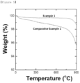
- the weight loss rate is 1% or less when heated up from 0 °C to 900 °C. Since the removal of the functional group was carried out through heat treatment, the weight loss was very slight in thermogravimetric analysis.
- the porous carbon material surface-modified with the hydrophilic functional group contains the functional group, resulting in a weight loss of 2% or more.
- the porous carbon material from which the functional group is removed by the heat treatment has a D/G peak ratio of 0.8 to 1.5 at the Raman measurement. If the ratio is less than 0.8, it means that the heat treatment has been performed at a high temperature of 2000 °C or higher, and thus the graphitization reaction occurs due to the high temperature, and damage to the porous carbon material occurs. If the ratio is higher than 1.5, the conductivity is greatly reduced.
- the porous carbon material may be at least one selected from the group consisting of carbon nanotubes, graphene, graphite, amorphous carbon, carbon black, and activated carbon.
- carbon nanotubes, graphite, and carbon black are preferable in terms of excellent electrical conductivity, specific surface area, and supported amount of sulfur.
- the carbon nanotubes may be single-walled carbon nanotubes (SWCNT) or multi-walled carbon nanotubes (MWCNT).
- the carbon nanotubes preferably have a diameter of 1 to 200 nm, more preferably 1 to 100 nm, and most preferably 1 to 50 nm. If the diameter of the carbon nanotubes exceeds 200 nm, there is a problem that the specific surface area is reduced, thereby reducing the reaction area with the electrolyte solution.
- the graphite may be one or more of artificial graphite and natural graphite.
- the natural graphite comprises flake graphite, high crystalline graphite, microcrystalline (or cryptocrystalline; amorphous) graphite and the like
- the artificial graphite comprises primary or electrographite, secondary graphite, graphite fiber and the like.
- the graphite particle can be used alone in one type or in combination of 2 or more types of graphite mentioned above.
- the graphite particles are not particularly limited in their crystal structures as long as they can reversibly intercalate lithium ions during charging/discharging.
- the graphite particles may have a plane spacing of 0.335 nm or more and less than 0.337 nm, for example, 0.335 nm or more and less than 0.337 nm, as measured by X-ray wide-angle diffraction.
- the size of the graphite particles is preferably the same or smaller than the size of the silicon-based particles in terms of uniform mixing and mixture density improvement.
- the average particle diameter of the graphite particles may be 20 ⁇ m or less, specifically for example 0.1 to 20 ⁇ m or less, more specifically 0.1 to 10 ⁇ m, 1 to 10 ⁇ m, or 1 to 5 ⁇ m.
- the carbon black may be, for example, at least one selected from the group consisting of acetylene black, Ketjen black, furnace black, oil-furnace black, Columbia carbon, channel black, lamp black, and thermal black.
- the particle size of the carbon black is not limited, but an average particle diameter of 0.01 to 0.5 ⁇ m is preferable in terms of securing a reaction area with an electrolyte solution.
- the sulfur is preferably inorganic sulfur or elemental sulfur (S 8 ).
- the porous carbon material and the sulfur are preferably mixed in a weight ratio of 1 : 1 to 1 : 9. If the content of the porous carbon material exceeds the above range, the content of sulfur, which is an active material, is lowered, causing problems in securing battery capacity. If the content of the porous carbon material is less than the above range, the content of the porous carbon material is insufficient to impart electrical conductivity. Therefore, the content of porous carbon material is properly adjusted within the above range.
- the method of complexing the sulfur-carbon composite of the present invention is not particularly limited in the present invention, and a method commonly used in the art may be used.
- a complexing method by simply mixing the porous carbon material having a specific surface area in the above range and sulfur and then heat-treating them may be used.
- the sulfur is supported on at least a portion of the inside and on the surface of the porous carbon material, and more sulfur is supported in the interior than on the surface.
- the inside of the porous carbon material means the pores of the porous carbon material.
- the diameter of the sulfur-carbon composite of the present invention is not particularly limited in the present invention, and may vary, but may be preferably 0.1 to 20 ⁇ m, more preferably 1 to 10 ⁇ m. When satisfying the above range, it is possible to manufacture the electrode with high loading.
- the present invention relates to a method for preparing a sulfur-carbon composite comprising the steps of:
- Step (a) is a step of heat-treating the porous carbon material surface-modified with the functional group to remove the functional group of the porous carbon material.
- the functional group is a hydrophilic functional group, preferably a hydroxyl group or a carboxyl group.
- the porous carbon material surface-modified with the functional group may be prepared by treating with acid.
- the acid may be at least one selected from nitric acid, sulfuric acid, and a mixed solution thereof.
- the porous carbon material which is surface-modified with a functional group, may be manufactured by a simple process of sonication or heat treatment after immersing the porous carbon material in an acid.
- the sonication may be performed by a sonicator commonly used in the art, and the treatment temperature is not particularly limited but is preferably 15 to 35 °C, preferably room temperature.
- the heat treatment it may be carried out in a heat resistant and pressure resistant container such as an autoclave, and the heating temperature is preferably 90 to 120 °C.
- This mixed solution treatment is carried out for 30 minutes to 4 hours, preferably 1 to 3 hours.
- the sonication and the heat treatment may be performed simultaneously, or they may be sequentially performed, such as the heat treatment after the sonication.
- the functional group of the porous carbon material is removed by heat-treating the porous carbon material surface-modified with the functional group.
- the heat treatment may be performed by heating up to 500 to 1000 °C at a rate of 5 to 20 °C/min, and then heat treatment for 1 to 5 hours at that temperature.
- rate of temperature increase is less than 5 °C/min, side reactions other than the functional group removal reaction may occur. If the rate of temperature increase exceeds 20 °C/min, the reaction may be proceeded at the exceeded temperature, which is not appropriate.
- the functional group may not be sufficiently removed. If the temperature exceeds 1000 °C, graphitization of the porous carbon material may be proceeded.
- the functional group may not be sufficiently removed. If the heat treatment time after the temperature increase exceeds 5 hours, side reactions other than the functional group removal reaction may occur.
- a porous carbon material from which the functional group of the porous carbon material surface-modified with the functional group was removed may be prepared.
- the heat treatment temperature is about 1500 °C or higher. At this temperature, not only the functional groups are removed from the porous carbon material but also the graphitization reaction occurs.
- thermogravimetric analysis TGA
- the weight loss rate is 1% or less when heated up from 0 °C to 900 °C. Since the removal of the functional group was carried out through heat treatment, the weight loss was very slight in thermogravimetric analysis.
- the porous carbon material surface-modified with the hydrophilic functional group contains the functional group, resulting in a weight loss of 2% or more.
- the porous carbon material from which the functional group is removed by the heat treatment has a D/G peak ratio of 0.8 to 1.5 at the Raman measurement. If the ratio is less than 0.8, it means that the heat treatment has been performed at a high temperature of 2000 °C or higher, and thus the graphitization reaction occurs due to the high temperature, and damage to the porous carbon material occurs. If the ratio is higher than 1.5, the conductivity is greatly reduced.
- Step (b) is a step of complexing the porous carbon material prepared in step (a), from which the functional group is removed, with sulfur powder to prepare a sulfur-carbon composite.
- the porous carbon material from which the functional group has been removed and sulfur are preferably combined in a weight ratio of 1 : 1 to 1 : 9. If the sulfur content is less than the above range, the amount of active material is insufficient to be used as a positive electrode active material, and if the porous carbon material is less than the above range, the electrical conductivity of the sulfur-carbon composite will not be sufficient. Therefore, the content of sulfur and carbon material is properly adjusted within the above range.
- the complexing method is not particularly limited, and methods commonly used in the art may be used, such as dry complexation or wet complexation such as spray coating. More specifically, a method can be used that allows molten sulfur to be evenly supported on the inside and on the surface of the porous carbon material from which the functional groups have been removed, by ball-milling and pulverizing the sulfur powder and the functional group-removed porous carbon material and then placing in an oven at 120 to 160 °C for 20 minutes to 1 hour.
- the specific surface area of the sulfur-carbon composite is 7 to 15 m 2 /g, preferably 8 to 15 m 2 /g. If the specific surface area of the sulfur-carbon composite is less than 7 m 2 /g, it means that sulfur is covering the surface of the porous carbon material, and that sulfur is not evenly supported on the porous carbon material, and thus the electrical conductivity of the sulfur-carbon composite can be reduced. If the specific surface area of the sulfur-carbon composite exceeds 20 m 2 /g, it means that sulfur is not properly supported inside the porous carbon material.
- the pore volume of the sulfur-carbon composite of the present invention is 0.1 to 0.3 cm 3 /g, preferably 0.1 to 0.15 cm 3 /g. If the pore volume of the sulfur-carbon composite is less than 0.1 cm 3 /g, it means that sulfur is covering the surface of the porous carbon material, and that sulfur is not evenly supported on the porous carbon material, and thus the electrical conductivity of the sulfur-carbon composite can be reduced. If the pore volume of the sulfur-carbon composite exceeds 0.3 cm 3 /g, it means that sulfur is not properly supported inside the porous carbon material.
- the present invention relates to a positive electrode for a lithium secondary battery comprising the sulfur-carbon composite of the present invention described above.
- the sulfur-carbon composite may be used as a positive electrode active material of a positive electrode for a lithium secondary battery, and the positive electrode for a lithium secondary battery may be preferably a positive electrode for a lithium-sulfur battery.
- the positive electrode may be formed by applying a positive electrode composition to the current collector and vacuum-drying it.
- the positive electrode current collector generally can be made in a thickness of 3 to 500 ⁇ m and is not particularly limited as long as it has high electrical conductivity without causing chemical changes in the battery.
- a conductive metal such as stainless steel, aluminum, copper, or titanium, etc.
- an aluminum current collector can be used as the positive electrode current collector, and preferably an aluminum current collector can be used.
- the positive electrode current collector may be formed in various forms such as film, sheet, foil, net, porous body, foam, or nonwoven fabric.
- the positive electrode composition may comprise the sulfur-carbon composite of the present invention as a positive electrode active material, and may further comprise a conductive material and a binder.
- the conductive material imparts additional conductivity to the positive electrode active material and serves to cause electrons to move smoothly in the positive electrode, and is not particularly limited as long as it does not cause chemical changes in the battery and provides an excellent electrical conductivity and a large surface area, but preferably a carbon-based material is used.
- the carbon-based material may be one selected from the group consisting of graphite-based materials such as natural graphite, artificial graphite, expanded graphite, and graphene; active carbon-based material; carbon black-based materials such as channel black, furnace black, thermal black, contact black, lamp black, and acetylene black; carbon fiber-based material; carbon nano structures such as carbon nanotube (CNT) and fullerene; and a combination thereof.
- graphite-based materials such as natural graphite, artificial graphite, expanded graphite, and graphene
- active carbon-based material such as channel black, furnace black, thermal black, contact black, lamp black, and acetylene black
- carbon fiber-based material carbon nano structures such as carbon nanotube (CNT) and fullerene
- metallic fiber such as metal mesh
- metallic powder such as copper (Cu), silver (Ag), nickel (Ni), and aluminum (Al)
- organic conductive materials such as polyphenylene derivatives may also be used according to purpose.
- the conductive materials may be used alone or in a combination thereof.
- the binder provides the positive electrode active material with the adhesion to the current collector.
- the binder should be well dissolved in a solvent, and the binder not only has to constitute a conductive network between the positive electrode active material and the conductive material, but also should have a moderate impregnation property for an electrolyte solution.
- the binder applicable to the present invention may be any binder known in the art, and specifically may be at least one selected from the group consisting of fluororesin-based binders comprising polyvinylidene fluoride (PVdF) or polytetrafluoroethylene (PTFE); rubber-based binders comprising styrene-butadiene rubber, acrylonitrile-butadiene rubber, and styrene-isoprene rubber; cellulosic binders comprising carboxy methyl cellulose (CMC), starch, hydroxypropyl cellulose, and regenerated cellulose; polyalcohol-based binder; polyolefin-based binders comprising polyethylene and polypropylene; polyimide-based binders, polyester-based binders, and silane-based binders, or a mixture or copolymer of two or more of these, but is not limited thereto.
- fluororesin-based binders comprising polyvinylidene flu
- the content of the binder resin may be, but is not limited to, 0.5 to 30 wt.% based on the total weight of the positive electrode composition. If the content of the binder resin is less than 0.5 wt.%, the physical properties of the positive electrode may be degraded and thus the positive electrode active material and conductive material may be eliminated. If the content exceeds 30 wt.%, the ratio of the active material and the conductive material in the positive electrode is relatively reduced and thus the capacity of the battery can be reduced.
- the positive electrode composition is prepared in slurry state and applied on the positive electrode current collector.
- the solvent according to the present invention may be water or an organic solvent.
- the organic solvent may be an organic solvent comprising at least one selected from the group consisting of dimethylformamide, isopropyl alcohol, acetonitrile, methanol, ethanol, and tetrahydrofuran.
- the mixing of the positive electrode composition can be carried out by a conventional method using a conventional mixer such as a paste mixer, a high-speed shear mixer, or a homo-mixer.
- a conventional mixer such as a paste mixer, a high-speed shear mixer, or a homo-mixer.
- the slurry can be coated on the current collector in an appropriate thickness depending on the viscosity of the slurry and the thickness of the positive electrode to be formed, and can be suitably selected within the range of 10 to 300 ⁇ m.
- the method of coating the slurry there is no limitation on the method of coating the slurry, and examples thereof may comprise doctor blade coating, dip coating, gravure coating, slit die coating, spin coating, comma coating, bar coating, reverse roll coating, screen coating, and cap coating methods.
- the present invention relates to a lithium secondary battery comprising a positive electrode; a negative electrode; a separator interposed between the positive electrode and the negative electrode; and an electrolyte solution, wherein the positive electrode is the positive electrode for the lithium secondary battery of the present invention described above.
- the lithium secondary battery of the present invention may be preferably a lithium-sulfur battery.
- the negative electrode may be composed of a current collector and a negative electrode active material layer formed on one or both surfaces thereof.
- the negative electrode may be a lithium metal plate.
- the current collector is for supporting the negative electrode active material and is not particularly limited as long as it is electrochemically stable in the voltage range of the lithium secondary battery while having excellent conductivity, and for example, copper, stainless steel, aluminum, nickel, titanium, palladium, sintered carbon, or copper or stainless steel whose surface is treated with carbon, nickel, silver or the like, or aluminum-cadmium alloy or the like may be used.
- the negative electrode current collector can enhance the bonding force with the negative electrode active material by having fine irregularities on its surface, and may be formed in various forms such as film, sheet, foil, mesh, net, porous body, foam, or nonwoven fabric.
- the negative electrode active material may comprise a material capable of reversibly intercalating or deintercalating lithium ion, a material capable of reacting with lithium ion to reversibly form lithium containing compounds, or lithium metal or lithium alloy.
- the material capable of reversibly intercalating or deintercalating lithium ion can be, for example, crystalline carbon, amorphous carbon, or a mixture thereof.
- the material capable of reacting with lithium ion to reversibly form lithium containing compounds may be, for example, tin oxide, titanium nitrate, or silicon.
- the lithium alloy may be, for example, an alloy of lithium (Li) and a metal selected from the group consisting of sodium (Na), potassium (K), rubidium (Rb), cesium (Cs), francium (Fr), beryllium (Be), magnesium (Mg), calcium (Ca), strontium (Sr), barium (Ba), radium (Ra), aluminum (Al), and tin (Sn).
- a metal selected from the group consisting of sodium (Na), potassium (K), rubidium (Rb), cesium (Cs), francium (Fr), beryllium (Be), magnesium (Mg), calcium (Ca), strontium (Sr), barium (Ba), radium (Ra), aluminum (Al), and tin (Sn).
- a separator is additionally comprised between the positive electrode and the negative electrode.
- the separator enables the transport of lithium ions between the positive electrode and the negative electrode while separating or insulating the positive electrode and the negative electrode from each other.
- the separator may be made of a porous, nonconductive or insulating material.
- the separator may be an independent member such as a film or a coating layer added to the positive electrode and/or the negative electrode.
- the material constituting the separator comprises, for example, but is not limited to, polyolefins such as polyethylene and polypropylene, glass fiber filter paper, and ceramic materials, and the thickness thereof may be about 5 to about 50 ⁇ m, preferably about 5 to about 25 ⁇ m.
- the electrolyte solution is a non-aqueous electrolyte containing lithium salts and is composed of a lithium salt and an electrolyte solution.
- the electrolyte solution non-aqueous organic solvents, organic solid electrolytes, and inorganic solid electrolytes may be used.
- lithium salts conventionally used in the electrolyte solution for the lithium-sulfur battery may be used without limitation.
- the lithium salt may comprise, for example, at least one selected from the group consisting of LiSCN, LiBr, LiI, LiPF 6 , LiBF 4 , LiB 10 Cl 10 , LiSO 3 CF 3 , LiCl, LiClO 4 , LiSO 3 CH 3 , LiB(Ph) 4 , LiC(SO 2 CF 3 ) 3 , LiN(SO 2 CF 3 ) 2 , LiCF 3 CO 2 , LiAsF 6 , LiSbF 6 , LiAlCl 4 , LiFSI, lithium chloroborane, lithium lower aliphatic carboxylate and the like.
- the concentration of the lithium salt in the electrolyte solution may be 0.2 to 2 M, preferably 0.6 to 2 M, more preferably, 0.7 to 1.7 M. If the concentration of the lithium salt is less than 0.2 M, the conductivity of the electrolyte solution may be lowered and thus the performance of the electrolyte solution may be deteriorated. If the concentration of the lithium salt exceeds 2 M, the viscosity of the electrolyte solution may increase and thus the mobility of the lithium ion may be reduced.
- the non-aqueous organic solvent should dissolve the lithium salt well, and the non-aqueous organic solvent of the present invention may comprise, for example, aprotic organic solvents such as N-methyl-2-pyrrolidinone, propylene carbonate, ethylene carbonate, butylene carbonate, dimethyl carbonate, diethyl carbonate, ethyl methyl carbonate, gamma-butyrolactone, 1,2-dimethoxyethane, 1,2-diethoxyethane, tetrahydroxy franc, 2-methyl tetrahydrofuran, dimethylsulfoxide, 1,3-dioxolane, 4-methyl-1,3-dioxen, diethylether, formamide, dimethylformamide, dioxolane, acetonitrile, nitromethane, methyl formate, methyl acetate, phosphate triester, trimethoxymethane, dioxolane derivatives, sulfolane, methyl sulfolane
- organic solid electrolyte for example, polyethylene derivatives, polyethylene oxide derivatives, polypropylene oxide derivatives, phosphate ester polymers, polyalginate lysine, polyester sulfide, polyvinyl alcohol, polyvinylidene fluoride, and polymers comprising ionic dissociation groups and the like can be used.
- the inorganic solid electrolyte for example, nitrides, halides, sulfates and the like of Li such as Li 3 N, LiI, Li 5 NI 2 , Li 3 N-LiI-LiOH, LiSiO 4 , LiSiO 4 -LiI-LiOH, Li 2 SiS 3 , Li 4 SiO 4 , Li 4 SiO 4 -LiI-LiOH, Li 3 PO 4 -Li 2 S-SiS 2 may be used.
- the electrolyte of the present invention for example, pyridine, triethylphosphite, triethanolamine, cyclic ether, ethylene diamine, n-glyme, hexaphosphoric triamide, nitrobenzene derivatives, sulfur, quinone imine dyes, N-substituted oxazolidinone, N,N-substituted imidazolidine, ethylene glycol dialkyl ether, ammonium salt, pyrrole, 2-methoxy ethanol, or aluminum trichloride, etc. may also be added for the purpose of improving charging/discharging characteristics, flame retardancy and the like.
- a halogen-containing solvent such as carbon tetrachloride, ethylene trifluoride or the like can be also added for the purpose of imparting nonflammability, and carbon dioxide gas can be further comprised for the purpose of improving storage characteristics at a high temperature, and fluoro-ethylene carbonate (FEC), propene sultone (PRS), fluoro-propylene carbonate (FPC) and the like can be further comprised.
- FEC fluoro-ethylene carbonate
- PRS propene sultone
- FPC fluoro-propylene carbonate
- a liquid electrolyte may be used or also an electrolyte separator form in a solid state may be used.
- a separator made of porous glass, plastic, ceramic, or polymer is further comprised as a physical separator having a function of physically separating the electrodes.
- the carbon nanotubes, from which the functional groups were removed, and sulfur were mixed at a weight ratio of 25:75, and reacted for 35 minutes at a temperature of 155 °C to prepare the sulfur-carbon composite having sulfur supported in the inside (pores) and on the surface of the carbon nanotubes ( FIGs. 1 and 2 ).
- Sulfur-carbon composites having sulfur supported in the inside (pores) and on the surface of carbon nanotubes were prepared in the same manner as in Example 1, except that carbon nanotubes (SUSN, HCNTS10) were used ( FIGs. 3 and 4 ).
- the carbon nanotubes (CNano, FT6120) surface-modified with a hydrophilic functional group and sulfur were mixed in a weight ratio of 25:75, and then reacted at a temperature of 155 °C for 35 minutes to form sulfur-carbon composite having sulfur supported in the inside (pores) and on the surface of the carbon nanotubes.
- Sulfur-carbon composite having sulfur supported in the inside (pores) and on the surface of the carbon nanotubes were prepared in the same manner as in Comparative Example 1, except that carbon nanotubes (SUSN, HCNTS10) surface-modified with hydrophilic functional groups were used.
- the carbon nanotubes, from which the functional groups were removed, and sulfur were mixed at a weight ratio of 25:75, and reacted for 35 minutes at a temperature of 155 °C to prepare sulfur-carbon composite having sulfur supported in the inside (pores) and on the surface of the carbon nanotubes.
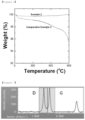
- Thermogravimetric analysis (TGA) of the carbon nanotubes of Examples 1 and 2, Comparative Example 1, and Comparative Example 2 was performed. The temperature was raised from 0 °C to 900 °C. At this time, the weight reduction rate was measured to determine whether the functional groups of the carbon nanotubes were removed.
- the carbon nanotubes of Examples 1 and 2 showed a weight reduction rate of about 1% or less even when the temperature was increased, thereby maintaining the weight. Accordingly, it can be seen through the heat treatment process of Examples 1 and 2 that the functional groups of the carbon nanotubes are removed, and that the functional groups of about 2 to 4% by weight are removed.
- the carbon nanotubes of Example 2 from which the functional group was removed by low temperature heat treatment at a temperature of 500 to 1000 °C of Comparative Example 2, showed a D/G ratio of 1.03. It was confirmed that the carbon nanotubes of Comparative Example 2 before the heat treatment showed a D/G ratio of 0.94, thereby indicating that the D/G ratio before and after the heat treatment was not significantly changed. From this, it can be seen that during the removal of functional groups, the degree of graphitization of carbon nanotubes does not change significantly.
- the carbon nanotubes of Comparative Example 3 which was heat-treated at a high temperature of 2000 °C, showed a D/G ratio of 0.51. The reason may be that the graphitization of the carbon nanotubes was progressed at that temperature and thus the G peak was increased.
- the heat treatment process for removing the functional group of the present invention selectively removes only the functional group without significantly changing the graphitization degree of the porous carbon material.
- Example 1 Example 2 Comparative Example 1 Comparative Example 2 Specific surface area 8.359m 2 /g 13.726m 2 /g 5.863m 2 /g 6.864m 2 /g Pore volume 0.106cm 3 /g 0.13cm 3 /g 0.08cm 3 /g 0.08cm 3 /g
- the sulfur-carbon composite comprising carbon nanotubes from which functional groups have been removed, has high specific surface area and pore volume, since sulfur is evenly supported in the pores and on the surfaces of the carbon nanotubes.
- the electrical conductivity of the sulfur-carbon composites prepared in Examples 1 and 2 and Comparative Examples 1 and 2 was measured using a powder resistance meter from HANTECH company.
- the sulfur-carbon composite comprising carbon nanotubes from which the functional groups were removed may have high electrical conductivity since sulfur is evenly supported in the pores and on the surfaces of the carbon nanotubes.
- the sulfur-carbon composites comprising the carbon nanotubes containing the functional groups did not show high electrical conductivity because sulfur covered the surface of the porous carbon material.
- Lithium-sulfur batteries (coin cells) were manufactured using the sulfur-carbon composites prepared in Examples 1 and 2 and Comparative Examples 1 and 2 as a positive electrode active material, respectively.
- a conductive material (Denka black) and 5 g of carboxymethyl cellulose (CMC) were added and mixed together with zirconia balls. Then, 3.6 g of sulfur-carbon composite and a predetermined amount of water were added and mixed again. Finally, 0.35 g of styrene-butadiene rubber (SBR) was added and mixed again to prepare a slurry.
- SBR styrene-butadiene rubber
- the prepared slurry was poured onto aluminum foil, coated with a blade coater to a thickness of 200 ⁇ m, and dried in an oven at 50 °C to prepare a positive electrode for a lithium-sulfur battery.
- a coin cell was assembled by placing a positive electrode, a separator (polyethylene), a lithium negative electrode, a gasket, a stainless steel coin, a spring, and an upper plate of stainless steel in turn on a lower plate of stainless steel and applying pressure thereto.
- a mixed solution of 1,3-dioxolane (DOL) : diethylene glycol dimethyl ether (DEGDME) 4 : 6 (v/v), into which 1 wt.% LiNO 3 in 1M LiTFSI was dissolved, as the electrolyte solution was injected onto the punched positive electrode.
- DOL 1,3-dioxolane
- DEGDME diethylene glycol dimethyl ether
- the lithium-sulfur batteries of Examples 1 and 2 and Comparative Examples 1 and 2 were tested for changes in charging/discharging characteristics using a charging/discharging measuring device.
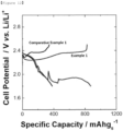
- the obtained battery was examined for initial capacity under the conditions of 0.1C/0.1C charging/discharging, and the results are shown in FIGs. 12 and 13 .
- the lithium-sulfur batteries comprising the sulfur-carbon composites of Examples 1 and 2 were found to have improved discharge capacity and overvoltage as compared to the lithium-sulfur batteries comprising the sulfur-carbon composites of Comparative Examples 1 and 2.
- the sulfur-carbon composites of Examples 1 and 2 evenly support sulfur. It was confirmed that the evenly supported sulfur improved the reactivity of the sulfur reduction reaction (S 8 + 16Li ⁇ 8Li 2 S), thereby increasing the discharge capacity and improving the overvoltage.
- sulfur covers the surface of the porous carbon material so that the reactivity of the sulfur reduction reaction did not improve, showing a lower result than Examples 1 and 2.
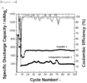
- the lifetime characteristics were measured by repeating 0.1C/0.1C charging/discharging for the first 3 cycles, then 0.2C/0.2C charging/discharging for 3 cycles, and then 0.5C/0.5C charging/discharging for 100 cycles, using the charging/discharging measuring device, and the results are shown in FIGs. 14 and 15 .
- the lithium-sulfur battery comprising sulfur-carbon composites of Examples 1 and 2 showed a result of maintaining capacity for 100 cycles.
- the lithium-sulfur battery comprising sulfur-carbon composites of Comparative Examples 1 and 2 showed a result of not maintaining capacity for 100 cycles.
- the lithium-sulfur batteries comprising the sulfur-carbon composites of Examples 1 and 2 have improved lifetime characteristics as compared to the lithium-sulfur batteries comprising the sulfur-carbon composites of Comparative Examples 1 and 2.
- carbon nanotubes of the sulfur-carbon composites of Examples 1 and 2 carry sulfur evenly as the functional groups are removed, thereby improving the lifetime characteristics of the battery comprising the same.
Landscapes
- Chemical & Material Sciences (AREA)
- General Chemical & Material Sciences (AREA)
- Chemical Kinetics & Catalysis (AREA)
- Electrochemistry (AREA)
- Engineering & Computer Science (AREA)
- Inorganic Chemistry (AREA)
- Materials Engineering (AREA)
- Organic Chemistry (AREA)
- Manufacturing & Machinery (AREA)
- Composite Materials (AREA)
- Nanotechnology (AREA)
- Battery Electrode And Active Subsutance (AREA)
- Carbon And Carbon Compounds (AREA)
Applications Claiming Priority (3)
| Application Number | Priority Date | Filing Date | Title |
|---|---|---|---|
| KR20180112639 | 2018-09-20 | ||
| KR1020190109637A KR102854271B1 (ko) | 2018-09-20 | 2019-09-04 | 황-탄소 복합체, 이의 제조방법, 이를 포함하는 리튬 이차전지용 양극 및 리튬 이차전지 |
| PCT/KR2019/011540 WO2020060084A1 (ko) | 2018-09-20 | 2019-09-06 | 황-탄소 복합체, 이의 제조방법, 이를 포함하는 리튬 이차전지용 양극 및 리튬 이차전지 |
Publications (3)
| Publication Number | Publication Date |
|---|---|
| EP3767715A1 EP3767715A1 (en) | 2021-01-20 |
| EP3767715A4 EP3767715A4 (en) | 2021-06-30 |
| EP3767715B1 true EP3767715B1 (en) | 2023-11-01 |
Family
ID=70003408
Family Applications (1)
| Application Number | Title | Priority Date | Filing Date |
|---|---|---|---|
| EP19863294.5A Active EP3767715B1 (en) | 2018-09-20 | 2019-09-06 | Sulfur-carbon composite, preparation method thereof, positive electrode for lithium secondary battery and lithium secondary battery comprising same |
Country Status (7)
| Country | Link |
|---|---|
| US (2) | US12191477B2 (enExample) |
| EP (1) | EP3767715B1 (enExample) |
| JP (1) | JP7167299B2 (enExample) |
| KR (2) | KR102854271B1 (enExample) |
| CN (1) | CN112088453B (enExample) |
| ES (1) | ES2972060T3 (enExample) |
| HU (1) | HUE064994T2 (enExample) |
Families Citing this family (2)
| Publication number | Priority date | Publication date | Assignee | Title |
|---|---|---|---|---|
| KR102848102B1 (ko) * | 2021-01-08 | 2025-08-19 | 주식회사 엘지에너지솔루션 | 황-탄소 복합체, 이의 제조방법, 및 이를 포함하는 리튬-황 전지 |
| CN119111002A (zh) * | 2022-04-27 | 2024-12-10 | 日亚化学工业株式会社 | 锂硫电池用碳材料及其制造方法 |
Family Cites Families (16)
| Publication number | Priority date | Publication date | Assignee | Title |
|---|---|---|---|---|
| CN102530926A (zh) * | 2010-12-10 | 2012-07-04 | 东丽纤维研究所(中国)有限公司 | 一种基于连二亚硫酸盐制备石墨烯的方法 |
| CN104094457B (zh) | 2011-09-30 | 2017-06-23 | 加州大学校务委员会 | 在高性能锂/硫电池中作为硫固定剂的氧化石墨烯 |
| DE102012209635A1 (de) * | 2012-06-08 | 2013-12-12 | Robert Bosch Gmbh | Verfahren zum Herstellen eines Polyacrylnitril-Schwefel-Kompositwerkstoffs |
| JP6011787B2 (ja) | 2012-08-09 | 2016-10-19 | ソニー株式会社 | 電極材料及びその製造方法、並びに、リチウム−硫黄二次電池 |
| KR20140079036A (ko) | 2012-12-18 | 2014-06-26 | 삼성전기주식회사 | 절연층 조성물, 및 이를 이용한 절연층을 포함하는 기판, 및 상기 기판의 제조방법 |
| KR101686640B1 (ko) | 2015-05-14 | 2016-12-14 | 부산대학교 산학협력단 | 고분자 코팅층을 갖는 질소도핑된 그래핀-유황 복합체의 제조방법, 이에 의하여 제조된 복합체 및 이를 이용한 리튬-황 이차전지 |
| KR101775782B1 (ko) | 2015-08-31 | 2017-09-11 | 국방과학연구소 | 단일벽 탄소나노튜브의 작용기 제거 방법 |
| EP3377444A4 (en) * | 2015-11-13 | 2019-04-03 | Robert Bosch GmbH | SULFUR-CARBON COMPOUND WITH HIGHLY GRAPHITE CARBON MATERIAL FOR LITHIUM SULFUR BATTERIES AND METHOD FOR THE PRODUCTION THEREOF |
| US10381646B2 (en) | 2015-12-24 | 2019-08-13 | Semiconductor Energy Laboratory Co., Ltd. | Secondary battery, graphene oxide, and manufacturing method thereof |
| KR101951275B1 (ko) | 2016-05-30 | 2019-02-22 | 한국화학연구원 | 카본블랙의 표면처리 방법 |
| KR20180017796A (ko) | 2016-08-11 | 2018-02-21 | 주식회사 엘지화학 | 황-탄소 복합체, 이의 제조방법 및 이를 포함하는 리튬-황 전지 |
| CN106602063B (zh) | 2016-12-30 | 2020-08-11 | 长兴德烯科技有限公司 | 一种石墨烯花的制备方法及其在锂硫电池中的应用 |
| CN107611395B (zh) | 2017-09-08 | 2020-10-27 | 中国科学院山西煤炭化学研究所 | 小尺寸石墨烯锂硫电池正极材料、其制备的锂硫电池及制备方法 |
| CN107946553B (zh) | 2017-10-25 | 2021-03-26 | 温州大学 | 高石墨化三维碳纳米管石墨烯复合材料及其制备与应用 |
| US11658293B2 (en) * | 2017-11-16 | 2023-05-23 | Lg Energy Solution, Ltd. | Sulfur-carbon composite, preparation method therefor, and lithium secondary battery comprising same |
| KR102229453B1 (ko) * | 2017-11-24 | 2021-03-17 | 주식회사 엘지화학 | 황-탄소 복합체, 그의 제조방법 및 이를 포함하는 리튬 이차전지 |
-
2019
- 2019-09-04 KR KR1020190109637A patent/KR102854271B1/ko active Active
- 2019-09-06 EP EP19863294.5A patent/EP3767715B1/en active Active
- 2019-09-06 HU HUE19863294A patent/HUE064994T2/hu unknown
- 2019-09-06 JP JP2021502687A patent/JP7167299B2/ja active Active
- 2019-09-06 US US17/043,877 patent/US12191477B2/en active Active
- 2019-09-06 CN CN201980030242.6A patent/CN112088453B/zh active Active
- 2019-09-06 ES ES19863294T patent/ES2972060T3/es active Active
-
2024
- 2024-10-23 US US18/924,219 patent/US20250046787A1/en active Pending
-
2025
- 2025-06-05 KR KR1020250073617A patent/KR20250088696A/ko active Pending
Also Published As
| Publication number | Publication date |
|---|---|
| EP3767715A4 (en) | 2021-06-30 |
| JP2021517110A (ja) | 2021-07-15 |
| KR102854271B1 (ko) | 2025-09-03 |
| ES2972060T3 (es) | 2024-06-11 |
| US12191477B2 (en) | 2025-01-07 |
| US20250046787A1 (en) | 2025-02-06 |
| KR20200033736A (ko) | 2020-03-30 |
| EP3767715A1 (en) | 2021-01-20 |
| JP7167299B2 (ja) | 2022-11-08 |
| KR20250088696A (ko) | 2025-06-17 |
| CN112088453B (zh) | 2023-11-24 |
| US20210036306A1 (en) | 2021-02-04 |
| CN112088453A (zh) | 2020-12-15 |
| HUE064994T2 (hu) | 2024-04-28 |
Similar Documents
| Publication | Publication Date | Title |
|---|---|---|
| KR102024900B1 (ko) | 금속 황화물 나노입자를 포함하는 리튬-황 전지용 양극 활물질 및 이의 제조방법 | |
| US20250046785A1 (en) | Cathode active material for lithium secondary battery, manufacturing method thereof, and lithium secondary battery comprising same | |
| KR101494715B1 (ko) | 리튬 이차 전지용 음극 활물질, 이의 제조 방법, 그리고 이를 포함하는 음극 및 리튬 이차 전지 | |
| JP6522167B2 (ja) | 金属ナノ粒子を含む正極活物質及び正極、それを含むリチウム−硫黄電池 | |
| EP3670449B1 (en) | Method for manufacture of sulfur-carbon composite | |
| US20250046787A1 (en) | Sulfur-carbon composite, preparation method thereof, positive electrode for lithium secondary battery and lithium second | |
| US11611066B2 (en) | Sulfur-carbon composite and method for preparing same | |
| KR102268182B1 (ko) | 황-탄소 복합체, 그의 제조방법 및 이를 포함하는 리튬 이차전지 | |
| US11652208B2 (en) | Sulfur-carbon composite, method for preparing same and lithium secondary battery comprising same | |
| KR20210016887A (ko) | 양극 활물질 제조 방법 및 양극 활물질 | |
| JP2022530839A (ja) | 表面にリン酸陰イオンが吸着されたオキシ水酸化硝酸鉄、この製造方法、上記表面にリン酸陰イオンが吸着されたオキシ水酸化硝酸鉄を含むリチウム二次電池用正極及びこれを含むリチウム二次電池 | |
| EP3809498B1 (en) | Cathode active material for lithium secondary battery | |
| KR20200121498A (ko) | 리튬 이차전지용 양극 슬러리 조성물, 이를 포함하는 양극 및 리튬 이차전지 | |
| KR102229459B1 (ko) | 리튬 이차전지용 양극 첨가제 및 이의 제조방법 | |
| KR20210004295A (ko) | 리튬 이차전지용 양극 및 리튬 이차전지 | |
| KR102864158B1 (ko) | 표면에 인산 음이온이 흡착된 옥시수산화질산철, 이의 제조방법, 상기 표면에 인산 음이온이 흡착된 옥시수산화질산철을 포함하는 리튬 이차전지용 양극 및 이를 포함하는 리튬 이차전지 | |
| CN121359250A (zh) | 用于制造用于锂离子电池的负极和负极材料的方法及其区分方法 | |
| KR20220103390A (ko) | 리튬 이차 전지용 양극 활물질, 이의 제조방법 및 이를 포함하는 리튬 이차 전지 |
Legal Events
| Date | Code | Title | Description |
|---|---|---|---|
| STAA | Information on the status of an ep patent application or granted ep patent |
Free format text: STATUS: THE INTERNATIONAL PUBLICATION HAS BEEN MADE |
|
| PUAI | Public reference made under article 153(3) epc to a published international application that has entered the european phase |
Free format text: ORIGINAL CODE: 0009012 |
|
| STAA | Information on the status of an ep patent application or granted ep patent |
Free format text: STATUS: REQUEST FOR EXAMINATION WAS MADE |
|
| 17P | Request for examination filed |
Effective date: 20201013 |
|
| AK | Designated contracting states |
Kind code of ref document: A1 Designated state(s): AL AT BE BG CH CY CZ DE DK EE ES FI FR GB GR HR HU IE IS IT LI LT LU LV MC MK MT NL NO PL PT RO RS SE SI SK SM TR |
|
| AX | Request for extension of the european patent |
Extension state: BA ME |
|
| A4 | Supplementary search report drawn up and despatched |
Effective date: 20210531 |
|
| RIC1 | Information provided on ipc code assigned before grant |
Ipc: H01M 4/36 20060101AFI20210525BHEP Ipc: H01M 4/38 20060101ALI20210525BHEP Ipc: H01M 4/62 20060101ALI20210525BHEP Ipc: H01M 10/052 20100101ALI20210525BHEP Ipc: C01B 17/02 20060101ALI20210525BHEP Ipc: C01B 32/168 20170101ALI20210525BHEP Ipc: H01M 4/04 20060101ALI20210525BHEP Ipc: H01M 4/133 20100101ALI20210525BHEP Ipc: H01M 4/1393 20100101ALI20210525BHEP Ipc: H01M 4/583 20100101ALI20210525BHEP Ipc: C01B 17/00 20060101ALI20210525BHEP Ipc: C01B 32/174 20170101ALI20210525BHEP Ipc: H01M 4/02 20060101ALN20210525BHEP |
|
| DAV | Request for validation of the european patent (deleted) | ||
| DAX | Request for extension of the european patent (deleted) | ||
| RAP1 | Party data changed (applicant data changed or rights of an application transferred) |
Owner name: LG ENERGY SOLUTION LTD. |
|
| RAP3 | Party data changed (applicant data changed or rights of an application transferred) |
Owner name: LG ENERGY SOLUTION, LTD. |
|
| GRAP | Despatch of communication of intention to grant a patent |
Free format text: ORIGINAL CODE: EPIDOSNIGR1 |
|
| STAA | Information on the status of an ep patent application or granted ep patent |
Free format text: STATUS: GRANT OF PATENT IS INTENDED |
|
| RIC1 | Information provided on ipc code assigned before grant |
Ipc: H01M 4/02 20060101ALN20230330BHEP Ipc: H01M 4/58 20100101ALI20230330BHEP Ipc: C01B 32/174 20170101ALI20230330BHEP Ipc: C01B 17/00 20060101ALI20230330BHEP Ipc: H01M 4/583 20100101ALI20230330BHEP Ipc: H01M 4/1393 20100101ALI20230330BHEP Ipc: H01M 4/133 20100101ALI20230330BHEP Ipc: H01M 4/04 20060101ALI20230330BHEP Ipc: C01B 32/168 20170101ALI20230330BHEP Ipc: C01B 17/02 20060101ALI20230330BHEP Ipc: H01M 10/052 20100101ALI20230330BHEP Ipc: H01M 4/62 20060101ALI20230330BHEP Ipc: H01M 4/38 20060101ALI20230330BHEP Ipc: H01M 4/36 20060101AFI20230330BHEP |
|
| INTG | Intention to grant announced |
Effective date: 20230417 |
|
| P01 | Opt-out of the competence of the unified patent court (upc) registered |
Effective date: 20230526 |
|
| GRAS | Grant fee paid |
Free format text: ORIGINAL CODE: EPIDOSNIGR3 |
|
| GRAA | (expected) grant |
Free format text: ORIGINAL CODE: 0009210 |
|
| STAA | Information on the status of an ep patent application or granted ep patent |
Free format text: STATUS: THE PATENT HAS BEEN GRANTED |
|
| AK | Designated contracting states |
Kind code of ref document: B1 Designated state(s): AL AT BE BG CH CY CZ DE DK EE ES FI FR GB GR HR HU IE IS IT LI LT LU LV MC MK MT NL NO PL PT RO RS SE SI SK SM TR |
|
| REG | Reference to a national code |
Ref country code: GB Ref legal event code: FG4D |
|
| REG | Reference to a national code |
Ref country code: CH Ref legal event code: EP |
|
| REG | Reference to a national code |
Ref country code: IE Ref legal event code: FG4D |
|
| REG | Reference to a national code |
Ref country code: DE Ref legal event code: R096 Ref document number: 602019040779 Country of ref document: DE |
|
| REG | Reference to a national code |
Ref country code: LT Ref legal event code: MG9D |
|
| REG | Reference to a national code |
Ref country code: NL Ref legal event code: MP Effective date: 20231101 |
|
| PG25 | Lapsed in a contracting state [announced via postgrant information from national office to epo] |
Ref country code: GR Free format text: LAPSE BECAUSE OF FAILURE TO SUBMIT A TRANSLATION OF THE DESCRIPTION OR TO PAY THE FEE WITHIN THE PRESCRIBED TIME-LIMIT Effective date: 20240202 |
|
| PG25 | Lapsed in a contracting state [announced via postgrant information from national office to epo] |
Ref country code: IS Free format text: LAPSE BECAUSE OF FAILURE TO SUBMIT A TRANSLATION OF THE DESCRIPTION OR TO PAY THE FEE WITHIN THE PRESCRIBED TIME-LIMIT Effective date: 20240301 |
|
| PG25 | Lapsed in a contracting state [announced via postgrant information from national office to epo] |
Ref country code: LT Free format text: LAPSE BECAUSE OF FAILURE TO SUBMIT A TRANSLATION OF THE DESCRIPTION OR TO PAY THE FEE WITHIN THE PRESCRIBED TIME-LIMIT Effective date: 20231101 |
|
| REG | Reference to a national code |
Ref country code: AT Ref legal event code: MK05 Ref document number: 1628252 Country of ref document: AT Kind code of ref document: T Effective date: 20231101 |
|
| PG25 | Lapsed in a contracting state [announced via postgrant information from national office to epo] |
Ref country code: NL Free format text: LAPSE BECAUSE OF FAILURE TO SUBMIT A TRANSLATION OF THE DESCRIPTION OR TO PAY THE FEE WITHIN THE PRESCRIBED TIME-LIMIT Effective date: 20231101 |
|
| PG25 | Lapsed in a contracting state [announced via postgrant information from national office to epo] |
Ref country code: AT Free format text: LAPSE BECAUSE OF FAILURE TO SUBMIT A TRANSLATION OF THE DESCRIPTION OR TO PAY THE FEE WITHIN THE PRESCRIBED TIME-LIMIT Effective date: 20231101 |
|
| REG | Reference to a national code |
Ref country code: HU Ref legal event code: AG4A Ref document number: E064994 Country of ref document: HU |
|
| PG25 | Lapsed in a contracting state [announced via postgrant information from national office to epo] |
Ref country code: NL Free format text: LAPSE BECAUSE OF FAILURE TO SUBMIT A TRANSLATION OF THE DESCRIPTION OR TO PAY THE FEE WITHIN THE PRESCRIBED TIME-LIMIT Effective date: 20231101 Ref country code: LT Free format text: LAPSE BECAUSE OF FAILURE TO SUBMIT A TRANSLATION OF THE DESCRIPTION OR TO PAY THE FEE WITHIN THE PRESCRIBED TIME-LIMIT Effective date: 20231101 Ref country code: IS Free format text: LAPSE BECAUSE OF FAILURE TO SUBMIT A TRANSLATION OF THE DESCRIPTION OR TO PAY THE FEE WITHIN THE PRESCRIBED TIME-LIMIT Effective date: 20240301 Ref country code: GR Free format text: LAPSE BECAUSE OF FAILURE TO SUBMIT A TRANSLATION OF THE DESCRIPTION OR TO PAY THE FEE WITHIN THE PRESCRIBED TIME-LIMIT Effective date: 20240202 Ref country code: BG Free format text: LAPSE BECAUSE OF FAILURE TO SUBMIT A TRANSLATION OF THE DESCRIPTION OR TO PAY THE FEE WITHIN THE PRESCRIBED TIME-LIMIT Effective date: 20240201 Ref country code: AT Free format text: LAPSE BECAUSE OF FAILURE TO SUBMIT A TRANSLATION OF THE DESCRIPTION OR TO PAY THE FEE WITHIN THE PRESCRIBED TIME-LIMIT Effective date: 20231101 Ref country code: PT Free format text: LAPSE BECAUSE OF FAILURE TO SUBMIT A TRANSLATION OF THE DESCRIPTION OR TO PAY THE FEE WITHIN THE PRESCRIBED TIME-LIMIT Effective date: 20240301 |
|
| PG25 | Lapsed in a contracting state [announced via postgrant information from national office to epo] |
Ref country code: SE Free format text: LAPSE BECAUSE OF FAILURE TO SUBMIT A TRANSLATION OF THE DESCRIPTION OR TO PAY THE FEE WITHIN THE PRESCRIBED TIME-LIMIT Effective date: 20231101 Ref country code: RS Free format text: LAPSE BECAUSE OF FAILURE TO SUBMIT A TRANSLATION OF THE DESCRIPTION OR TO PAY THE FEE WITHIN THE PRESCRIBED TIME-LIMIT Effective date: 20231101 Ref country code: PL Free format text: LAPSE BECAUSE OF FAILURE TO SUBMIT A TRANSLATION OF THE DESCRIPTION OR TO PAY THE FEE WITHIN THE PRESCRIBED TIME-LIMIT Effective date: 20231101 Ref country code: NO Free format text: LAPSE BECAUSE OF FAILURE TO SUBMIT A TRANSLATION OF THE DESCRIPTION OR TO PAY THE FEE WITHIN THE PRESCRIBED TIME-LIMIT Effective date: 20240201 Ref country code: LV Free format text: LAPSE BECAUSE OF FAILURE TO SUBMIT A TRANSLATION OF THE DESCRIPTION OR TO PAY THE FEE WITHIN THE PRESCRIBED TIME-LIMIT Effective date: 20231101 Ref country code: HR Free format text: LAPSE BECAUSE OF FAILURE TO SUBMIT A TRANSLATION OF THE DESCRIPTION OR TO PAY THE FEE WITHIN THE PRESCRIBED TIME-LIMIT Effective date: 20231101 |
|
| REG | Reference to a national code |
Ref country code: ES Ref legal event code: FG2A Ref document number: 2972060 Country of ref document: ES Kind code of ref document: T3 Effective date: 20240611 |
|
| PG25 | Lapsed in a contracting state [announced via postgrant information from national office to epo] |
Ref country code: DK Free format text: LAPSE BECAUSE OF FAILURE TO SUBMIT A TRANSLATION OF THE DESCRIPTION OR TO PAY THE FEE WITHIN THE PRESCRIBED TIME-LIMIT Effective date: 20231101 |
|
| PG25 | Lapsed in a contracting state [announced via postgrant information from national office to epo] |
Ref country code: CZ Free format text: LAPSE BECAUSE OF FAILURE TO SUBMIT A TRANSLATION OF THE DESCRIPTION OR TO PAY THE FEE WITHIN THE PRESCRIBED TIME-LIMIT Effective date: 20231101 |
|
| PG25 | Lapsed in a contracting state [announced via postgrant information from national office to epo] |
Ref country code: SK Free format text: LAPSE BECAUSE OF FAILURE TO SUBMIT A TRANSLATION OF THE DESCRIPTION OR TO PAY THE FEE WITHIN THE PRESCRIBED TIME-LIMIT Effective date: 20231101 |
|
| PG25 | Lapsed in a contracting state [announced via postgrant information from national office to epo] |
Ref country code: SM Free format text: LAPSE BECAUSE OF FAILURE TO SUBMIT A TRANSLATION OF THE DESCRIPTION OR TO PAY THE FEE WITHIN THE PRESCRIBED TIME-LIMIT Effective date: 20231101 Ref country code: SK Free format text: LAPSE BECAUSE OF FAILURE TO SUBMIT A TRANSLATION OF THE DESCRIPTION OR TO PAY THE FEE WITHIN THE PRESCRIBED TIME-LIMIT Effective date: 20231101 Ref country code: IT Free format text: LAPSE BECAUSE OF FAILURE TO SUBMIT A TRANSLATION OF THE DESCRIPTION OR TO PAY THE FEE WITHIN THE PRESCRIBED TIME-LIMIT Effective date: 20231101 Ref country code: EE Free format text: LAPSE BECAUSE OF FAILURE TO SUBMIT A TRANSLATION OF THE DESCRIPTION OR TO PAY THE FEE WITHIN THE PRESCRIBED TIME-LIMIT Effective date: 20231101 Ref country code: DK Free format text: LAPSE BECAUSE OF FAILURE TO SUBMIT A TRANSLATION OF THE DESCRIPTION OR TO PAY THE FEE WITHIN THE PRESCRIBED TIME-LIMIT Effective date: 20231101 Ref country code: CZ Free format text: LAPSE BECAUSE OF FAILURE TO SUBMIT A TRANSLATION OF THE DESCRIPTION OR TO PAY THE FEE WITHIN THE PRESCRIBED TIME-LIMIT Effective date: 20231101 |
|
| REG | Reference to a national code |
Ref country code: DE Ref legal event code: R097 Ref document number: 602019040779 Country of ref document: DE |
|
| PLBE | No opposition filed within time limit |
Free format text: ORIGINAL CODE: 0009261 |
|
| STAA | Information on the status of an ep patent application or granted ep patent |
Free format text: STATUS: NO OPPOSITION FILED WITHIN TIME LIMIT |
|
| 26N | No opposition filed |
Effective date: 20240802 |
|
| PG25 | Lapsed in a contracting state [announced via postgrant information from national office to epo] |
Ref country code: SI Free format text: LAPSE BECAUSE OF FAILURE TO SUBMIT A TRANSLATION OF THE DESCRIPTION OR TO PAY THE FEE WITHIN THE PRESCRIBED TIME-LIMIT Effective date: 20231101 |
|
| PG25 | Lapsed in a contracting state [announced via postgrant information from national office to epo] |
Ref country code: SI Free format text: LAPSE BECAUSE OF FAILURE TO SUBMIT A TRANSLATION OF THE DESCRIPTION OR TO PAY THE FEE WITHIN THE PRESCRIBED TIME-LIMIT Effective date: 20231101 |
|
| PGFP | Annual fee paid to national office [announced via postgrant information from national office to epo] |
Ref country code: ES Payment date: 20241010 Year of fee payment: 6 |
|
| PG25 | Lapsed in a contracting state [announced via postgrant information from national office to epo] |
Ref country code: MC Free format text: LAPSE BECAUSE OF FAILURE TO SUBMIT A TRANSLATION OF THE DESCRIPTION OR TO PAY THE FEE WITHIN THE PRESCRIBED TIME-LIMIT Effective date: 20231101 |
|
| REG | Reference to a national code |
Ref country code: CH Ref legal event code: PL |
|
| PG25 | Lapsed in a contracting state [announced via postgrant information from national office to epo] |
Ref country code: LU Free format text: LAPSE BECAUSE OF NON-PAYMENT OF DUE FEES Effective date: 20240906 |
|
| PG25 | Lapsed in a contracting state [announced via postgrant information from national office to epo] |
Ref country code: CH Free format text: LAPSE BECAUSE OF NON-PAYMENT OF DUE FEES Effective date: 20240930 |
|
| PG25 | Lapsed in a contracting state [announced via postgrant information from national office to epo] |
Ref country code: IE Free format text: LAPSE BECAUSE OF NON-PAYMENT OF DUE FEES Effective date: 20240906 |
|
| PG25 | Lapsed in a contracting state [announced via postgrant information from national office to epo] |
Ref country code: FI Free format text: LAPSE BECAUSE OF FAILURE TO SUBMIT A TRANSLATION OF THE DESCRIPTION OR TO PAY THE FEE WITHIN THE PRESCRIBED TIME-LIMIT Effective date: 20231101 |
|
| PGFP | Annual fee paid to national office [announced via postgrant information from national office to epo] |
Ref country code: DE Payment date: 20250820 Year of fee payment: 7 |
|
| PGFP | Annual fee paid to national office [announced via postgrant information from national office to epo] |
Ref country code: BE Payment date: 20250820 Year of fee payment: 7 Ref country code: HU Payment date: 20250929 Year of fee payment: 7 Ref country code: GB Payment date: 20250820 Year of fee payment: 7 |
|
| PGFP | Annual fee paid to national office [announced via postgrant information from national office to epo] |
Ref country code: FR Payment date: 20250821 Year of fee payment: 7 |
|
| PG25 | Lapsed in a contracting state [announced via postgrant information from national office to epo] |
Ref country code: RO Free format text: LAPSE BECAUSE OF FAILURE TO SUBMIT A TRANSLATION OF THE DESCRIPTION OR TO PAY THE FEE WITHIN THE PRESCRIBED TIME-LIMIT Effective date: 20231101 |