EP3766612B1 - Rohrbearbeitungsvorrichtung - Google Patents
Rohrbearbeitungsvorrichtung Download PDFInfo
- Publication number
- EP3766612B1 EP3766612B1 EP20188101.8A EP20188101A EP3766612B1 EP 3766612 B1 EP3766612 B1 EP 3766612B1 EP 20188101 A EP20188101 A EP 20188101A EP 3766612 B1 EP3766612 B1 EP 3766612B1
- Authority
- EP
- European Patent Office
- Prior art keywords
- cutting
- pipe
- tool base
- cutting insert
- insert
- Prior art date
- Legal status (The legal status is an assumption and is not a legal conclusion. Google has not performed a legal analysis and makes no representation as to the accuracy of the status listed.)
- Active
Links
Images




Classifications
-
- B—PERFORMING OPERATIONS; TRANSPORTING
- B23—MACHINE TOOLS; METAL-WORKING NOT OTHERWISE PROVIDED FOR
- B23B—TURNING; BORING
- B23B5/00—Turning-machines or devices specially adapted for particular work; Accessories specially adapted therefor
- B23B5/16—Turning-machines or devices specially adapted for particular work; Accessories specially adapted therefor for bevelling, chamfering, or deburring the ends of bars or tubes
- B23B5/167—Tools for chamfering the ends of bars or tubes
-
- B—PERFORMING OPERATIONS; TRANSPORTING
- B23—MACHINE TOOLS; METAL-WORKING NOT OTHERWISE PROVIDED FOR
- B23B—TURNING; BORING
- B23B27/00—Tools for turning or boring machines; Tools of a similar kind in general; Accessories therefor
- B23B27/06—Profile cutting tools, i.e. forming-tools
-
- B—PERFORMING OPERATIONS; TRANSPORTING
- B23—MACHINE TOOLS; METAL-WORKING NOT OTHERWISE PROVIDED FOR
- B23B—TURNING; BORING
- B23B27/00—Tools for turning or boring machines; Tools of a similar kind in general; Accessories therefor
- B23B27/14—Cutting tools of which the bits or tips or cutting inserts are of special material
- B23B27/141—Specially shaped plate-like cutting inserts, i.e. length greater or equal to width, width greater than or equal to thickness
- B23B27/145—Specially shaped plate-like cutting inserts, i.e. length greater or equal to width, width greater than or equal to thickness characterised by having a special shape
-
- B—PERFORMING OPERATIONS; TRANSPORTING
- B23—MACHINE TOOLS; METAL-WORKING NOT OTHERWISE PROVIDED FOR
- B23B—TURNING; BORING
- B23B3/00—General-purpose turning-machines or devices, e.g. centre lathes with feed rod and lead screw; Sets of turning-machines
- B23B3/22—Turning-machines or devices with rotary tool heads
- B23B3/26—Turning-machines or devices with rotary tool heads the tools of which perform a radial movement; Rotary tool heads thereof
-
- B—PERFORMING OPERATIONS; TRANSPORTING
- B23—MACHINE TOOLS; METAL-WORKING NOT OTHERWISE PROVIDED FOR
- B23B—TURNING; BORING
- B23B5/00—Turning-machines or devices specially adapted for particular work; Accessories specially adapted therefor
- B23B5/16—Turning-machines or devices specially adapted for particular work; Accessories specially adapted therefor for bevelling, chamfering, or deburring the ends of bars or tubes
- B23B5/161—Devices attached to the workpiece
-
- B—PERFORMING OPERATIONS; TRANSPORTING
- B23—MACHINE TOOLS; METAL-WORKING NOT OTHERWISE PROVIDED FOR
- B23B—TURNING; BORING
- B23B2200/00—Details of cutting inserts
- B23B2200/04—Overall shape
- B23B2200/0447—Parallelogram
-
- B—PERFORMING OPERATIONS; TRANSPORTING
- B23—MACHINE TOOLS; METAL-WORKING NOT OTHERWISE PROVIDED FOR
- B23B—TURNING; BORING
- B23B2200/00—Details of cutting inserts
- B23B2200/36—Other features of cutting inserts not covered by B23B2200/04 - B23B2200/32
- B23B2200/3627—Indexing
-
- B—PERFORMING OPERATIONS; TRANSPORTING
- B23—MACHINE TOOLS; METAL-WORKING NOT OTHERWISE PROVIDED FOR
- B23B—TURNING; BORING
- B23B2205/00—Fixation of cutting inserts in holders
- B23B2205/10—Fixation of cutting inserts in holders using two or more fixation screws
-
- B—PERFORMING OPERATIONS; TRANSPORTING
- B23—MACHINE TOOLS; METAL-WORKING NOT OTHERWISE PROVIDED FOR
- B23B—TURNING; BORING
- B23B2210/00—Details of turning tools
- B23B2210/02—Tool holders having multiple cutting inserts
-
- B—PERFORMING OPERATIONS; TRANSPORTING
- B23—MACHINE TOOLS; METAL-WORKING NOT OTHERWISE PROVIDED FOR
- B23B—TURNING; BORING
- B23B2215/00—Details of workpieces
- B23B2215/72—Tubes, pipes
-
- B—PERFORMING OPERATIONS; TRANSPORTING
- B23—MACHINE TOOLS; METAL-WORKING NOT OTHERWISE PROVIDED FOR
- B23B—TURNING; BORING
- B23B2220/00—Details of turning, boring or drilling processes
- B23B2220/04—Chamferring
-
- B—PERFORMING OPERATIONS; TRANSPORTING
- B23—MACHINE TOOLS; METAL-WORKING NOT OTHERWISE PROVIDED FOR
- B23B—TURNING; BORING
- B23B2220/00—Details of turning, boring or drilling processes
- B23B2220/28—Parting off and chamferring simultaneously
-
- B—PERFORMING OPERATIONS; TRANSPORTING
- B23—MACHINE TOOLS; METAL-WORKING NOT OTHERWISE PROVIDED FOR
- B23B—TURNING; BORING
- B23B5/00—Turning-machines or devices specially adapted for particular work; Accessories specially adapted therefor
- B23B5/16—Turning-machines or devices specially adapted for particular work; Accessories specially adapted therefor for bevelling, chamfering, or deburring the ends of bars or tubes
- B23B5/161—Devices attached to the workpiece
- B23B5/163—Devices attached to the workpiece with an external clamping device
Definitions
- the present disclosure generally relates to pipe machining apparatuses and cutting tools and, more particularly, to pipe machining apparatuses and cutting tools including cutting inserts.
- Pipe machining apparatuses are capable of machining objects, such as pipes, in a variety of different manners.
- pipes are cut along a plane perpendicular to a longitudinal axis of the pipe, thereby provided a flat-cut end of the pipe.
- pipes may be cut with a bevel along an axis or plane transverse to a longitudinal axis of the pipe.
- Pipe machining apparatuses may also include multiple cutting tools for cutting multiple bevels into a pipe. For example, when a pipe is cut, it is cut into two pieces.
- the pipe machining apparatus may include a first cutting tool to bevel an end of the first cut piece of pipe and a second cutting tool to bevel an end of the second cut piece of pipe.
- Pipe machining apparatuses may also be capable of cutting bevels into the ends of the pipe at multiple angles.
- a large variety of cutting tools are required to provide the variety of bevel cuts.
- a user would be required to keep track of the large variety of tools, which can be cumbersome and the possibility of losing one or more cutting tools is high.
- cutting tools due to the types of objects cut and the conditions in which the pipe machining apparatus operates, cutting tools must be made of durable and expensive material. Thus, such cutting tools are expensive. Expensive cutting tools combined with the requirement of maintaining large quantities of tools in order to perform the wide variety of bevel cuts results in an expensive endeavor. Additionally, losing and damaging cutting tools results in expensive replacement of the cutting tools.
- prior patent document US 20140096663A1 An example of a pipe machining apparatus in accordance with the preamble of claim is described in prior patent document US 20140096663A1 .
- the pipe machining apparatus is formed of two joined-together semicircular sections and includes a frame and a tool carrier.
- the tool carrier includes one or more tool supports which support tools for performing a cutting or machining operation on the pipe as the tools rotate circumferentially about the pipe.
- prior patent document US 20090052999A1 describes an example of an indexable cutting insert used with a tool holder for a pipe beveling machine.
- the present invention provides a pipe machining apparatus as defined in appended claim 1.
- a pipe machining apparatus 20 configured to machine pipes P of varying diameters.
- the apparatus 20 completely cuts through pipes P.
- the apparatus 20 prepares an end of a pipe P for coupling to another pipe.
- the apparatus 20 both completely cuts and prepares a pipe P for coupling to another pipe.
- cutting and/or preparing an end of a pipe P may result in a cut end of the pipe P being cut along a plane generally perpendicular to a longitudinal axis A of the pipe P or cut along a plane transverse to the longitudinal axis A of the pipe P.
- cutting an end of the pipe P along a transverse plane may be referred to as a bevel cut and result in a beveled end of the pipe P.
- Beveled ends of a pipe may be cut along a wide variety of transverse planes and at a wide variety of angles relative to the longitudinal axis A of the pipe P.
- the beveled ends may be cut along a plane that is traverse to the longitudinal axis A of the pipe at about a 30 degree angle.
- the beveled ends may be cut along a plane that is traverse to the longitudinal axis A of the pipe at about a 37.5 degree angle.
- the pipe machining apparatus 20 is formed of two joined-together semicircular sections 24A, 24B and includes a frame 28 and a tool carrier 32.
- the two sections 24A, 24B together comprise the frame 28 and the tool carrier 32 such that a first portion of the frame 28 and a first portion of the tool carrier 32 are included in one section 24A and a second portion of the frame 28 and a second portion of the tool carrier 32 are included in the other section 24B.
- the frame 28 has a column 36 extending outwardly of the two semicircular sections 24A, 24B and houses a pinion gear configured to couple with a suitable drive motor, such as, for example, an air motor, with suitable gear reduction means.
- the frame 28 is configured to couple and be fixed relative to a pipe P, and the tool carrier 32 is rotatable relative to the fixed frame 28 and the pipe P.
- the motor is configured to rotate the tool carrier 32 relative to the frame 28 through a gear train in the column 36.
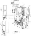
- the rotatable tool carrier 32 includes one or more tool supports 48 (two tool supports 48 shown in the illustrated example), which support tools 52, 53, 54 for performing cutting or machining operations on the pipe P as the tools 52, 53, 54 rotate circumferentially about the pipe P.
- the tool supports 48 are coupled to the tool carrier 32 by a plurality of coupling members 50.
- the machining operation performed by the tool 52 may form a straight edge generally perpendicular to a longitudinal axis A of the pipe P.
- the tools 53, 54 form bevels on ends 56, 58 of the two cut pieces P1, P2 of the pipe P that are along planes 60, 62 transverse to the longitudinal axis A of the pipe P.
- the transverse planes 60, 62 may be at any angle relative to the longitudinal axis A of the pipe P other than ninety degrees. For purposes of demonstrating principles of the present disclosure, the transverse planes 60, 62 will be described as being at about 30 degrees from perpendicularity to the longitudinal axis A of the pipe P or at about 37.5 degrees from perpendicularity to the longitudinal axis A of the pipe P.
- the apparatus 20 includes four adjustable clamp members or coupling members 68 engageable with an exterior of the pipe P and having suitable adjustability to couple and concentrically locate the apparatus 20 to the pipe P.
- One or more projections may be adjustably movable into and out of a path of an advancement member 84 coupled to each tool support 48 to advance the tools 52, 53, 54 toward the pipe P.
- the apparatus 20 may include any number of projections for engaging advancement members 84.
- Tool 52 cuts a groove 86 into the pipe P and tools 53, 54 are configured to bevel ends 56, 58 of cut pieces P1, P2 of a pipe P at desired angles.
- the tool 53 bevels an end 56 of a first cut piece P1 of pipe and tool 54 bevels an end 58 of a second cut piece P2 of pipe.
- the tool support 48 supports both tools 53, 54 for beveling ends 56, 58 of both cut pieces P1, P2 of a pipe.
- tools 53, 54 cut bevels along planes 60, 62 that are transverse to the longitudinal axis A of the pipe and at about 37.5 degrees from perpendicularity to the longitudinal axis A.
- Tools 53, 54 are interchangeable with other tools that cut bevels along planes that are transverse to the longitudinal axis A of the pipe and at different angles from perpendicularity to the longitudinal axis A.
- tools 53A, 54A may be interchanged with tools 53, 54 and may bevel ends 56, 58 of the two cut pieces P1, P2 of pipe at about 30 degrees from perpendicularity to the longitudinal axis A of the pipe.
- the tool 53A is illustrated and is configured to bevel an end 56 of a first cut piece P1 of the pipe.
- the bevel cut into the end 56 of the first cut piece P1 of pipe may be referred to as an inside bevel and tool 53A may be referred to as an inside bevel tool.
- the tool 53A includes a base 100A and a cutting insert 104 coupled to the base 100A.
- the cutting insert 104 may be coupled to the base 100A in a variety of manners. .In the illustrated example, the cutting insert 104 is coupled to the base 100A with two coupling members or fasteners 108. In other examples, the cutting insert 104 may be coupled to the base 100A using any number of fasteners.
- base 100A defines a projection or lip 112A having an engagement surface 116A that is configured to be engaged by the cutting insert 104.
- the base 100A also defines coupling apertures 120A therein configured to receive the coupling members 108 therein.
- the base 100A may include any number of coupling apertures 120A to correspond to the number of coupling members 108.
- the cutting insert 104 includes a first cutting edge 136, a second cutting edge 132 positioned opposite the first cutting edge 136, and third and fourth edges 124, 128 opposite each other and between the first and second cutting edges 136, 132.
- the first and second cutting edges 136, 132 are generally parallel to each other and the third and fourth edges 124, 128 are generally parallel to each other.
- the edges of the cutting insert 104 may be oriented differently relative to each other.
- the cutting insert 104 also defines apertures 140 there through that are alignable with coupling apertures 120A defined in the base 100A.
- the coupling members 108 are positioned in the aligned apertures 120A, 140 therein to couple the insert 104 to the base 100A.
- the cutting insert 104 may include any number of apertures 140 to correspond to the number of coupling members 108 and coupling apertures 120A in the base 100A.
- the second cutting edge 132 of the cutting insert 104 engages the engagement surface 116A of the base 100A.
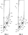
- the lip 112A, the engagement surface 116A, the location of the coupling apertures 120A and the shape of the cutting insert 104 cooperate to ensure the cutting insert 104 is at an appropriate orientation to bevel the end 56 of the first cut piece P1 of the pipe at an appropriate angle ⁇ .
- the cutting insert 104 may also be rotated 180 degrees to bring the first cutting edge 136 of the cutting insert 104 into engagement with the engagement surface 116A of the lip 112A.
- the two cutting edges 132, 136 may provide the cutting insert 104 with additional life compared to a cutting insert that only includes one cutting edge.
- the cutting insert 104 is the portion of the cutting tool 53A that engages, cuts and bevels the pipe P.
- the cutting insert 104 may be made of a material appropriate for cutting a pipe P while the base 100A of the cutting tool 53A may be made of a different material.
- the material from which the cutting insert 104 is made may be more expensive of a material than the material from which the base 100A is made.
- Typical cutting tools may be made completely of the material required to cut a pipe.
- the total cost of the cutting tool 53A may be reduced from past cutting tools made completely of a material required to cut a pipe.
- the tool 53 is illustrated and is configured to bevel an end 56 of a first cut piece P1 of the pipe.
- Tools 53 and 53A may be interchangeably coupled to the tool support 48 to bevel an end 56 of the first cut piece P1 of the pipe at various angles ⁇ or ⁇ .
- the bevel cut into the end 56 of the first cut piece P1 of pipe by the tool 53 may be referred to as an inside bevel and tool 53 may be referred to as an inside bevel tool.
- the tool 53 includes a base 100 and the cutting insert 104 coupled to the base 100.
- the cutting insert 104 is the same cutting insert 104 that is coupled to the base 100A of the tool 53A.
- the cutting insert 104 is configured to be interchangeably coupled to either the base 100A of tool 53A or the base 100 of tool 53. In this manner, only one cutting insert 104 is required to bevel the end 56 of the first cut piece P1 of the pipe at varying angles ⁇ , ⁇ and along various transverse planes 60, 60A.
- the cutting insert 104 is coupled to the base 100 of tool 53 in a similar manner to the base 100A of tool 53A since the cutting insert 104 is the same. That is, in the illustrated example, the cutting insert 104 is coupled to the base 100 with the two coupling members or fasteners 108.
- the same alternative examples described above in connection with coupling the cutting insert 104 to the base 100A of tool 53A also apply to coupling the cutting insert 104 to the base 100 of tool 53 since the cutting insert 104 is coupled similarly to both the base 100A of tool 53A and the base 100 of tool 53.
- the base 100 of tool 53 also defines a projection or lip 112 having an engagement surface 116 that is configured to be engaged by the cutting insert 104.
- the base 100 also defines coupling apertures 120 therein configured to receive the coupling members 108 therein.
- the lip 112 the engagement surface 116, the location of the coupling apertures 120 and the shape of the cutting insert 104 cooperate to ensure the cutting insert 104 is at an appropriate orientation to bevel the end 56 of the first cut piece P1 of the pipe at an appropriate angle ⁇ .
- the cutting insert 104 may also be rotated 180 degrees to bring the first cutting edge 136 of the cutting insert 104 into engagement with the engagement surface 116 of the lip 112.
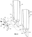
- the cutting insert 104 is illustrated in a manner that demonstrates interchangeable coupling of the cutting insert 104 with either the base 100A of tool 53A or the base 100 of cutting tool 53.
- the elements of the bases 100, 100A and the cutting insert 104 position the cutting insert 104 in the appropriate orientation to bevel the end 56 of the first cut piece P1 of pipe at multiple angles ⁇ , ⁇ and along multiple planes 60, 60A transverse to the longitudinal axis A of the pipe P.
- the tool 54A is illustrated and is configured to bevel an end 58 of a second cut piece P2 of the pipe.
- the bevel cut into the end 58 of the second cut piece P2 of pipe may be referred to as an outside bevel and tool 54A may be referred to as an outside bevel tool.
- the tool 54A includes a base 200A and a cutting insert 204 coupled to the base 200A.
- the cutting insert 204 may be coupled to the base 200A in a variety of manners.
- the cutting insert 204 is coupled to the base 200A with two coupling members or fasteners 208.
- the cutting insert 204 may be coupled to the base 200A using any number of fasteners 208.
- the base 200A defines a projection or lip 212A having an engagement surface 216A that is configured to be engaged by the cutting insert 204.
- the base 200A also defines coupling apertures 220A therein configured to receive the coupling members 208 therein.
- the base 200A may include any number of coupling apertures 220A to correspond to the number of coupling members 208.
- the cutting insert 204 includes a first cutting edge 236, a second cutting edge 232 positioned opposite the first cutting edge 236, and third and fourth edges 224, 228 opposite each other and between the first and second cutting edges 236, 232.
- the first and second cutting edges 236, 232 are generally parallel to each other and the third and fourth edges 224, 228 are generally parallel to each other.
- the edges of the cutting insert 204 may be oriented differently relative to each other.
- the cutting insert 204 also defines apertures 240 there through that are alignable with coupling apertures 220A defined in the base 200A.
- the coupling members 208 are positionable in the aligned apertures 220A, 240 to couple the insert 204 to the base 200A.
- the cutting insert 204 may include any number of apertures 240 to correspond to the number of coupling members 208 and coupling apertures 220A in the base 200A.
- the second cutting edge 232 of the cutting insert 204 engages the engagement surface 216A of the base 200A.
- the lip 212A, the engagement surface 216A, the location of the coupling apertures 220A and the shape of the cutting insert 204 cooperate to ensure the cutting insert 204 is at an appropriate orientation to bevel the end 58 of the second cut piece P2 of the pipe at an appropriate angle a.
- the two cutting edges 232, 236 may provide the cutting insert with additional life compared to a cutting insert that only includes one cutting edge.
- the cutting insert 204 is the portion of the cutting tool 54A that engages, cuts and bevels the pipe P.
- the cutting insert 204 may be made of a material appropriate for cutting a pipe P while the base 200A of the cutting tool 54A may be made of a different material.
- the material from which the cutting insert 204 is made may be more expensive of a material than the material from which the base 200A is made.
- Typical cutting tools may be made completely of the material required to cut a pipe.
- the total cost of the cutting tool 54A may be reduced from past cutting tools made completely of a material required to cut a pipe P.
- the tool 54 is illustrated and is configured to bevel an end 58 of a second cut piece P2 of the pipe.
- Tools 54 and 54A may be interchangeably coupled to the tool support 48 to bevel an end 58 of the second cut piece P2 of the pipe at various angles ⁇ or ⁇ .
- the bevel cut into the end 58 of the second cut piece P2 of pipe by the tool 54 may be referred to as an outside bevel and tool 54 may be referred to as an outside bevel tool.
- the tool 54 includes a base 200 and the cutting insert 204 coupled to the base 200.
- the cutting insert 204 is the same cutting insert 204 that is coupled to the base 200A of the tool 54A.
- the cutting insert 204 is configured to be interchangeably coupled to either the base 200A of tool 54A or the base 200 of tool 54. In this manner, only one cutting insert 204 is required to bevel the end 58 of the second cut piece P2 of the pipe at varying angles ⁇ , ⁇ and along various transverse planes 62, 62A.
- the cutting insert 204 is coupled to the base 200 of tool 54 in a similar manner to the base 200A of tool 54A since the cutting insert 204 is the same. That is, in the illustrated example, the cutting insert 204 is coupled to the base 200 with two coupling members or fasteners 208.
- the same alternative examples described above in connection with coupling the cutting insert 204 to the base 200A of tool 54A also apply to coupling the cutting insert 204 to the base 200 of tool 54 since the cutting insert 204 is coupled similarly to both the base 200A of tool 54A and the base 200 of tool 54.
- the base 200 of tool 54 also defines a projection or lip 212 having an engagement surface 216 that is configured to be engaged by the cutting insert 204.
- the base 200 also defines coupling apertures 220 therein configured to receive the coupling members 208 therein.
- the lip 212, the engagement surface 216, the location of the coupling apertures 220 and the shape of the cutting insert 204 cooperate to ensure the cutting insert 204 is at an appropriate orientation to bevel the end 58 of the second cut piece P2 of the pipe at an appropriate angle ⁇ .
- the cutting insert 204 may also be rotated 180 degrees to bring the first cutting edge 236 of the cutting insert 204 into engagement with the engagement surface 216 of the lip 212.
- the cutting insert 204 is illustrated in a manner that demonstrates interchangeable coupling of the cutting insert 204 with either the base 200A of tool 54A or the base 200 of cutting tool 54.
- the elements of the bases 200, 200A and the cutting insert 204 position the cutting insert 204 in the appropriate orientation to bevel the end 58 of the second cut piece P2 of pipe at multiple angles ⁇ , ⁇ and along multiple planes 62, 62A transverse to the longitudinal axis A of the pipe P.
- any orientation or directional terms herein such as, for example, “top”, “bottom, “front, “rear”, “back”, “left”, “right”, “side”, etc., is not intended to imply only a single orientation of the item with which it is associated or to limit the present disclosure in any manner.
- the use of such orientation or directional terms is intended to assist with the understanding of principles disclosed herein and to correspond to the exemplary orientation illustrated in the drawings.
- the pipe machining apparatus and cutting tools may be utilized in any orientation and use of such terms is intended to correspond to the exemplary orientation of the pipe machining apparatus and cutting tools illustrated in the drawings.
- the use of these terms in association with the pipe machining apparatus and cutting tools is not intended to limit the pipe machining apparatus and cutting tools to a single orientation or to limit the pipe machining apparatus and cutting tools in any manner.
Landscapes
- Engineering & Computer Science (AREA)
- Mechanical Engineering (AREA)
- Cutting Tools, Boring Holders, And Turrets (AREA)
- Turning (AREA)
Claims (12)
- Rohrbearbeitungsvorrichtung (20), aufweisend:einen Rahmen (28), der so konfiguriert ist, dass er um eine Außenfläche eines Rohrs (P) herum montiert und relativ zu dem Rohr (P) fixiert werden kann;einen Werkzeugträger (32), der beweglich mit dem Rahmen (28) gekoppelt ist, sodass er sich um das Rohr (P) drehen kann;einen Werkzeughalter (48), der mit dem Werkzeugträger (32) gekoppelt und mit diesem beweglich ist;eine erste Schneidwerkzeugbasis (100), eine zweite Schneidwerkzeugbasis (100A), eine dritte Schneidwerkzeugbasis (200) und eine vierte Schneidwerkzeugbasis (200A);wobei die erste Schneidwerkzeugbasis (100) und die zweite Schneidwerkzeugbasis (100A) konfiguriert sind, austauschbar mit dem Werkzeughalter (48) gekoppelt zu werden;wobei die dritte Schneidwerkzeugbasis (200) und die vierte Schneidwerkzeugbasis (200A) konfiguriert sind, austauschbar mit dem Werkzeughalter (48) gekoppelt zu werden;dadurch gekennzeichnet, dass die Vorrichtung einen ersten Schneideinsatz (104) und einen zweiten Schneideinsatz (204) aufweist;
dass der Werkzeughalter (48) konfiguriert ist, gleichzeitig eine der ersten und zweiten Schneidwerkzeugbasen (100, 100A) und eine der dritten und vierten Schneidwerkzeugbasen (200, 200A) so zu halten, dass der erste Schneideinsatz (104) so positioniert ist, dass er ein Ende (56) eines ersten Schnittstücks (Pl) eines Rohrs (P) anschrägt, und der zweite Schneideinsatz (204) so positioniert ist, dass er ein Ende (58) eines zweiten Schnittstücks (P2) eines Rohrs (P) anschrägt, das an das Ende (56) des ersten Schnittstücks (Pl) angrenzt;dass die erste Schneidwerkzeugbasis (100) eine erste Lippe (112) und eine erste Fläche (116) auf der ersten Lippe (112) beinhaltet, wobei sich die erste Fläche (116) in einem ersten Winkel erstreckt; unddie zweite Schneidwerkzeugbasis (100A) eine zweite Lippe (112A) und eine zweite Fläche (116A) auf der zweiten Lippe (112A) beinhaltet, wobei sich die zweite Fläche (116A) in einem zweiten Winkel erstreckt, der sich von dem ersten Winkel unterscheidet;dass der erste Schneideinsatz (104) austauschbar mit der ersten Schneidwerkzeugbasis (100) und der zweiten Schneidwerkzeugbasis (100A) gekoppelt ist, wobei der erste Schneideinsatz (104) eine Schneidkante (124) beinhaltet, die konfiguriert ist, das Ende (56) des ersten Schnittstücks (Pl) zu schneiden,wobei der erste Schneideinsatz (104) konfiguriert ist, mit der ersten Fläche (116) auf der ersten Lippe (112) in Eingriff zu kommen, wenn er mit der ersten Schneidwerkzeugbasis (100) gekoppelt ist, sodass der erste Schneideinsatz (104) in einem ersten Schneidwinkel ausgerichtet ist, um einen ersten Schnitt durchzuführen; undwobei der erste Schneideinsatz (104) konfiguriert ist, mit der zweiten Fläche (116A) auf der zweiten Lippe (112A) in Eingriff zu kommen, wenn er mit der zweiten Schneidwerkzeugbasis (100A) gekoppelt ist, sodass der erste Schneideinsatz (104) in einem zweiten Schneidwinkel ausgerichtet ist, um einen zweiten Schnitt durchzuführen, wobei sich der zweite Schneidwinkel von dem ersten Schneidwinkel unterscheidet;dass die dritte Schneidwerkzeugbasis (200) eine dritte Lippe (212) und eine dritte Fläche (216) auf der dritten Lippe (212) beinhaltet, wobei sich die dritte Fläche (216) in einem dritten Winkel erstreckt; unddie vierte Schneidwerkzeugbasis (200A) eine vierte Lippe (212A) und eine vierte Fläche (216A) auf der vierten Lippe (212A) beinhaltet, wobei sich die vierte Fläche (216A) in einem vierten Winkel erstreckt, der sich von dem dritten Winkel unterscheidet; unddass der zweite Schneideinsatz (204) austauschbar mit der dritten Schneidwerkzeugbasis (200) und der vierten Schneidwerkzeugbasis (200A) gekoppelt ist, wobei der zweite Schneideinsatz (204) eine Schneidkante (224) beinhaltet, die konfiguriert ist, das Ende (58) des zweiten Schnittstücks (P2) zu schneiden,wobei der zweite Schneideinsatz (204) konfiguriert ist, mit der dritten Fläche (216) auf der dritten Lippe (212) in Eingriff zu kommen, wenn er mit der dritten Schneidwerkzeugbasis (200) gekoppelt ist, sodass der zweite Schneideinsatz (204) in einem dritten Schneidwinkel ausgerichtet ist, um einen dritten Schnitt durchzuführen; undwobei der zweite Schneideinsatz (204) konfiguriert ist, mit der vierten Fläche (216A) auf der vierten Lippe (212A) in Eingriff zu kommen, wenn er mit der vierten Schneidwerkzeugbasis (200A) gekoppelt ist, sodass der zweite Schneideinsatz (204) in einem vierten Schneidwinkel ausgerichtet ist, um einen vierten Schnitt durchzuführen, wobei sich der vierte Schneidwinkel von dem dritten Schneidwinkel unterscheidet. - Rohrbearbeitungsvorrichtung (20) nach Anspruch 1, wobei der erste und dritte Winkel etwa 30 Grad und der zweite und vierte Winkel etwa 37,5 Grad betragen.
- Rohrbearbeitungsvorrichtung (20) nach Anspruch 1, wobei die Schneidkante jedes des ersten und zweiten Schneideinsatzes (104, 204) eine erste Schneidkante (136, 236) ist und jeder des ersten und zweiten Schneideinsatzes (104, 204) ferner eine zweite Schneidkante (132, 232) beinhaltet.
- Rohrbearbeitungsvorrichtung (20) nach Anspruch 1, wobei der erste und der zweite Schneideinsatz (104, 204) aus einem ersten Material hergestellt sind, zumindest eine der ersten Schneidwerkzeugbasis (100) und der zweiten Schneidwerkzeugbasis (100A) aus einem zweiten Material hergestellt ist, das sich von dem ersten Material unterscheidet, und zumindest eine der dritten Schneidwerkzeugbasis (200) und der vierten Schneidwerkzeugbasis (200A) aus dem zweiten Material hergestellt ist.
- Rohrbearbeitungsvorrichtung (20) nach Anspruch 1, wobei jede Schneidwerkzeugbasis (100, 100A, 200, 200A) eine Kopplungsöffnung (120, 120A, 220, 220A) definiert und jeder Schneideinsatz (104, 204) eine Einsatzöffnung (140, 240) definiert, wobei die Rohrbearbeitungsvorrichtung (20) ferner Kopplungselemente (108) aufweist, die austauschbar in die Einsatzöffnungen (140, 204) und die Kopplungsöffnungen (120, 240) eingesetzt werden können, wenn sie zum austauschbaren Koppeln des ersten und zweiten Schneideinsatzes (104, 204) mit der jeweiligen Schneidwerkzeugbasis (100, 100A, 200, 200A) ausgerichtet sind.
- Rohrbearbeitungsvorrichtung (20) nach Anspruch 1, wobei der erste und der zweite Schneideinsatz (104, 204) jeweils aufweisen:eine erste Schneidkante (136, 236);eine zweite Schneidkante (132, 232) gegenüber der ersten Schneidkante;eine dritte Kante (124, 224), die sich zwischen der ersten Schneidkante und der zweiten Schneidkante erstreckt; undeine vierte Kante (128, 228), die der dritten Kante gegenüberliegt und sich zwischen der ersten Schneidkante und der zweiten Schneidkante erstreckt.
- Rohrbearbeitungsvorrichtung (20) nach Anspruch 6, wobei die erste Schneidkante (136, 236) und die zweite Schneidkante (132, 232) im Allgemeinen parallel zueinander sind.
- Rohrbearbeitungsvorrichtung (20) nach Anspruch 7, wobei die dritte Kante (124, 224) und die vierte Kante (128, 228) im Allgemeinen parallel zueinander sind.
- Rohrbearbeitungsvorrichtung (20) nach Anspruch 6, wobei die erste Schneidkante (136, 236) und die zweite Schneidkante (132, 232) nicht senkrecht zu den dritten und vierten Kanten (124, 128, 224, 228) stehen.
- Rohrbearbeitungsvorrichtung (20) nach Anspruch 6, ferner aufweisend eine Kopplungsöffnung (140, 240), die durch jeden des ersten und zweiten Schneideinsatzes (104, 204) definiert ist.
- Rohrbearbeitungsvorrichtung (20) nach Anspruch 9, wobei jeder des ersten und zweiten Schneideinsatzes (104, 204) konfiguriert ist, mit einer entsprechenden Schneidwerkzeugbasis (100, 100A, 200, 200A) in einer ersten Ausrichtung gekoppelt zu werden, in der die erste Schneidkante (136, 236) zum Schneiden des Rohrs (P) positioniert ist, und in einer zweiten Ausrichtung, in der die zweite Schneidkante (132, 232) zum Schneiden des Rohrs (P) positioniert ist.
- Rohrbearbeitungsvorrichtung (20) nach Anspruch 11, wobei die zweite Schneidkante (132, 232) konfiguriert ist, mit dem Schneideinsatz (104, 204) in der ersten Ausrichtung in die jeweilige Schneidwerkzeugbasis (100, 100A, 200, 200A) einzugreifen und die erste Kante (136, 236) konfiguriert ist, mit dem Schneideinsatz (104, 204) in der zweiten Ausrichtung in die Schneidwerkzeugbasis (100, 100A, 200, 200A) einzugreifen.
Applications Claiming Priority (3)
| Application Number | Priority Date | Filing Date | Title |
|---|---|---|---|
| US14/527,141 US20160121406A1 (en) | 2014-10-29 | 2014-10-29 | Interchangeable cutting inserts and methods associated with the same |
| PCT/US2015/043356 WO2016069076A1 (en) | 2014-10-29 | 2015-08-03 | Interchangeable cutting inserts and methods associated with the same |
| EP15756266.1A EP3212355A1 (de) | 2014-10-29 | 2015-08-03 | Austauschbare schneideinsätze und verfahren in verbindung damit |
Related Parent Applications (1)
| Application Number | Title | Priority Date | Filing Date |
|---|---|---|---|
| EP15756266.1A Division EP3212355A1 (de) | 2014-10-29 | 2015-08-03 | Austauschbare schneideinsätze und verfahren in verbindung damit |
Publications (2)
| Publication Number | Publication Date |
|---|---|
| EP3766612A1 EP3766612A1 (de) | 2021-01-20 |
| EP3766612B1 true EP3766612B1 (de) | 2024-10-02 |
Family
ID=54011071
Family Applications (3)
| Application Number | Title | Priority Date | Filing Date |
|---|---|---|---|
| EP17203518.0A Withdrawn EP3308885A1 (de) | 2014-10-29 | 2015-08-03 | Einheit zum schneiden von rohren und rohrbearbeitungsvorrichtung |
| EP20188101.8A Active EP3766612B1 (de) | 2014-10-29 | 2015-08-03 | Rohrbearbeitungsvorrichtung |
| EP15756266.1A Withdrawn EP3212355A1 (de) | 2014-10-29 | 2015-08-03 | Austauschbare schneideinsätze und verfahren in verbindung damit |
Family Applications Before (1)
| Application Number | Title | Priority Date | Filing Date |
|---|---|---|---|
| EP17203518.0A Withdrawn EP3308885A1 (de) | 2014-10-29 | 2015-08-03 | Einheit zum schneiden von rohren und rohrbearbeitungsvorrichtung |
Family Applications After (1)
| Application Number | Title | Priority Date | Filing Date |
|---|---|---|---|
| EP15756266.1A Withdrawn EP3212355A1 (de) | 2014-10-29 | 2015-08-03 | Austauschbare schneideinsätze und verfahren in verbindung damit |
Country Status (3)
| Country | Link |
|---|---|
| US (2) | US20160121406A1 (de) |
| EP (3) | EP3308885A1 (de) |
| WO (1) | WO2016069076A1 (de) |
Families Citing this family (11)
| Publication number | Priority date | Publication date | Assignee | Title |
|---|---|---|---|---|
| US20160121406A1 (en) | 2014-10-29 | 2016-05-05 | Illinois Tool Works Inc. | Interchangeable cutting inserts and methods associated with the same |
| NL1041522B1 (en) * | 2015-10-15 | 2017-05-02 | Wavin Bv | A cutting tool and a branch connection device comprising a cutting tool. |
| US10675692B2 (en) * | 2016-08-25 | 2020-06-09 | Illinois Tool Works Inc. | Systems, apparatuses and methods of machining pipes and/or pipe flanges |
| CN110997199B (zh) * | 2017-08-18 | 2023-08-25 | 伊利诺斯工具制品有限公司 | 可互换切削刀片及包括其的管材切削组装件/加工设备 |
| WO2019083961A1 (en) | 2017-10-27 | 2019-05-02 | Tri Tool Inc. | PIPE CHAMFINTING MACHINE SYSTEM |
| US11282591B2 (en) | 2018-02-05 | 2022-03-22 | Optum, Inc. | Device for the centralized management of medical tests and methods for using the same |
| IT201900002815A1 (it) * | 2019-02-27 | 2020-08-27 | Blm Spa | Apparecchiatura per il taglio orbitale e la calibratura di tubi |
| US20220355386A1 (en) * | 2019-09-27 | 2022-11-10 | Team Industrial Services, Inc. | Pipe cutting apparatus having a hand guard |
| DE102020214901A1 (de) | 2020-11-26 | 2022-06-02 | MAPAL Fabrik für Präzisionswerkzeuge Dr. Kress KG | Schneidplatte zur Einstichbearbeitung, Schneidplatten-Kit mit zwei solchen Schneidplatten, Schneidplattenhalter für solche Schneidplatten, und Verfahren zum Herstellen eines Einstichs |
| US11980954B1 (en) * | 2021-02-23 | 2024-05-14 | ABG Design LLC | Portable automated notching machine |
| CN114473574B (zh) * | 2022-03-01 | 2024-03-15 | 重庆太仓科技有限公司 | 一种用于摩托车气缸体的车削一体化智能加工设备 |
Citations (5)
| Publication number | Priority date | Publication date | Assignee | Title |
|---|---|---|---|---|
| DE3303058A1 (de) * | 1983-01-29 | 1984-08-02 | Eugen 7250 Leonberg Hausch | Einrichtung an drehmaschinen zur lagerung eines drehstahl-einsatzes |
| US7104171B1 (en) * | 2005-05-14 | 2006-09-12 | Kennametal Inc. | Toolholder and toolholder assembly for a cutting insert positioned at a non-conventional height |
| US20070098509A1 (en) * | 2005-11-03 | 2007-05-03 | Hall J Randall | Milling head for removing heat dissipating elements from a tube |
| EP1920862A2 (de) * | 2006-11-07 | 2008-05-14 | SCF Snc di Colpani Gianfranco e Pier Giuseppe | Schneideinsatz und Werkzeughalter |
| DE102009040840A1 (de) * | 2009-09-09 | 2011-03-10 | Illinois Tool Works Inc., Glenview | Rohrbearbeitungsvorrichtung mit einer Schneideinrichtung |
Family Cites Families (87)
| Publication number | Priority date | Publication date | Assignee | Title |
|---|---|---|---|---|
| US2734256A (en) | 1956-02-14 | Cutting tool | ||
| US1459805A (en) | 1920-11-17 | 1923-06-26 | Tasker Walter Tom | Tool and tool holder for turning, planing, and like operations |
| US1634394A (en) * | 1922-08-26 | 1927-07-05 | Henry R Bernard | Method of and device for preventing freezing of motor-cooling systems |
| GB320809A (en) | 1928-12-05 | 1929-10-24 | Cammell Laird & Co Ltd | Improvements in or relating to turning and boring tools |
| US2201183A (en) | 1938-08-31 | 1940-05-21 | Elmer E Kelley | Machine tool |
| US2363160A (en) | 1943-09-21 | 1944-11-21 | Sundstrom Henry | Toolholder |
| US2598581A (en) | 1948-09-04 | 1952-05-27 | Kennametal Inc | Cutting tool |
| US2800703A (en) | 1953-07-08 | 1957-07-30 | Ford Motor Co | Rotating tool bit |
| GB810512A (en) * | 1956-08-10 | 1959-03-18 | Liverpool Tool And Gauge Ltd | Improvements in or relating to lathe and like cutting tools |
| US3097417A (en) | 1957-10-25 | 1963-07-16 | Tool holder with replaceable tip | |
| DE1054805B (de) * | 1957-12-17 | 1959-04-09 | Immelborn Hartmetallwerk | Achtschneidige, an Klemmstahlhaltern geklemmte Wegwerfplatte und deren Anordnung auf einem Klemmstahlhalter |
| US3084416A (en) | 1959-12-28 | 1963-04-09 | Gen Electric | Cutting tool |
| NL255794A (de) * | 1960-09-12 | |||
| US3136031A (en) | 1961-07-11 | 1964-06-09 | James P Cassidy | Tool holder |
| DE1477396B2 (de) | 1963-09-05 | 1971-04-01 | Hertel, Karl, 8500 Nürnberg | Schneidwerkzeug insbesondere zum drehen |
| US3176377A (en) | 1964-02-26 | 1965-04-06 | Valeron Corp | Pressed pin cutting tool holder |
| US3286562A (en) | 1964-12-09 | 1966-11-22 | Robert E Curran | Tangent form tool |
| GB1099961A (en) | 1965-03-24 | 1968-01-17 | Marwin Anstey Ltd | Improvements in or relating to tool holders |
| CH454574A (it) | 1966-05-14 | 1968-04-15 | U S A P Utensileria Speciale A | Testa di fresa a lame poligonali |
| US3339256A (en) | 1967-01-20 | 1967-09-05 | Arthur A Melinder | Turning and boring tool |
| CH480117A (de) | 1967-09-16 | 1969-10-31 | Reinert Robert | Stahlhalterspannkopf für Drehbänke |
| US3546759A (en) | 1967-11-01 | 1970-12-15 | Frank Sirola | Cutting tool |
| US3545060A (en) | 1968-05-20 | 1970-12-08 | Mitchell Kezran | Interchangeable insert and holder assembly |
| FR1598540A (de) | 1968-12-12 | 1970-07-06 | ||
| US3595107A (en) * | 1969-11-05 | 1971-07-27 | Stephen Dackow | Plastic pipe tapering device |
| DE2004387A1 (de) | 1970-01-31 | 1971-09-30 | Deutsche Edelstahlwerke Ag | Wendeschneidplatte für Kopierdrehmeißel |
| US3848303A (en) | 1971-05-28 | 1974-11-19 | Sandvik Ab | Cutting insert and cutting tool assembly |
| GB1380523A (en) | 1973-02-07 | 1975-01-15 | Santana A Z | Apparatus for cutting and or bevelling pipes |
| CH570840A5 (de) | 1973-03-20 | 1975-12-31 | Zabaleta Santana Agustin | |
| CH569539A5 (en) | 1973-09-24 | 1975-11-28 | Stoll Herbert | Lathe tool cutting insert holder - has hard metal insert pulled onto seat by clamp through holder |
| DE2363660A1 (de) | 1973-12-20 | 1975-06-26 | Kraftwerk Union Ag | Doppeldrehmeissel |
| AT361269B (de) | 1978-09-28 | 1981-02-25 | Ver Edelstahlwerke Ag | Prismatischer schneideinsatz |
| IL58006A (en) | 1979-08-08 | 1983-02-23 | Iscar Ltd | Cutting insert with chip control means |
| US4340324A (en) | 1980-08-28 | 1982-07-20 | Kennametal Inc. | Cutting insert |
| DE3128121C2 (de) | 1981-07-16 | 1983-08-18 | Komet Stahlhalter- Und Werkzeugfabrik Robert Breuning Gmbh, 7122 Besigheim | Drehwerkzeug für die Endenbearbeitung von Wellen, Zapfen, Rohren und dergleichen |
| DE8120797U1 (de) * | 1981-07-16 | 1982-12-30 | Komet Stahlhalter- Und Werkzeugfabrik Robert Breuning Gmbh, 7122 Besigheim | Drehwerkzeug fuer die endenbearbeitung von wellen, zapfen, rohren u.dgl. |
| CH667407A5 (fr) * | 1986-03-27 | 1988-10-14 | Stellram Sa | Fraise a plaquettes de coupe amovibles. |
| AT386144B (de) | 1986-05-23 | 1988-07-11 | Muellheim Ag Utilis | Drehstahl mit einem auswechselbaren drei- oder viereckigen wendeschneidplaettchen |
| US4739685A (en) * | 1987-01-12 | 1988-04-26 | Ricci Donato L | Split frame portable machining lathe |
| US4919573A (en) | 1987-09-22 | 1990-04-24 | Mitsubishi Kinzoku Kabushiki Kaisha | Ball end mill |
| SU1634394A1 (ru) * | 1988-07-13 | 1991-03-15 | Фрунзенский Филиал Головного Специального Производственного Конструкторско-Технологического Бюро По Рациональному Применению Режущего Инструмента | Торцова фреза |
| US5054342A (en) * | 1989-05-09 | 1991-10-08 | The E.H. Wachs Company | Pipe machining apparatus |
| US5082401A (en) | 1990-12-18 | 1992-01-21 | Kennametal Inc. | Cutting insert for light feed rate |
| DE4207353C2 (de) | 1992-03-05 | 1997-06-05 | Schmidt Hans Guenter | Werkzeughalter für ein Schneidwerkzeug |
| US5503507A (en) | 1994-03-04 | 1996-04-02 | Valenite Inc. | High speed cutting insert with improved chip groove |
| DE4437426A1 (de) | 1994-10-20 | 1996-04-25 | Widia Heinlein Gmbh | Fräser |
| JP3147762B2 (ja) | 1996-01-31 | 2001-03-19 | 三菱マテリアル株式会社 | スローアウェイチップのクランプ機構 |
| US5893683A (en) | 1997-04-29 | 1999-04-13 | Ingersoll Cutting Tool Company | Indexable insert router |
| US6079302A (en) * | 1999-01-12 | 2000-06-27 | Gudleske; Gustave F. | Saw and saw blade for simultaneously cutting and beveling |
| US6409435B1 (en) | 2000-07-03 | 2002-06-25 | Valenite Inc. | Cutting tool and method of locating cutting insert |
| SE524560C2 (sv) | 2001-01-30 | 2004-08-24 | Sandvik Ab | Verktygshållare med flexibelt fastspänningsorgan |
| EP1240961A1 (de) | 2001-03-13 | 2002-09-18 | Applitec Moutier S.A. | Schneidwerkzeug |
| DE10163473C1 (de) * | 2001-12-17 | 2003-07-10 | Mapal Fab Praezision | Werkzeug zur spanabtragenden Bearbeitung von Rohrenden |
| DE50313469D1 (de) | 2002-06-21 | 2011-03-31 | Utilis Ag | Decolletagewerkzeug in der Form einer Wendeschneidplatte |
| EP1470878A1 (de) | 2003-04-22 | 2004-10-27 | Applitec Moutier S.A. | Schneidwerkzeug mit Schneideinsatz |
| SE526586C2 (sv) | 2003-11-25 | 2005-10-11 | Sandvik Intellectual Property | Verktyg för spånavskiljande bearbetning innefattande en han/hon-koppling mellan skärdel och hållardel |
| US7004689B2 (en) | 2004-01-09 | 2006-02-28 | Kennametal Inc. | High-speed milling cutter and insert |
| JP4639862B2 (ja) | 2004-03-26 | 2011-02-23 | 三菱マテリアル株式会社 | スローアウェイチップのクランプ機構 |
| US20050271483A1 (en) | 2004-06-02 | 2005-12-08 | Sandvik Ab | Indexable cutting inserts and methods for producing the same |
| JP4427689B2 (ja) | 2004-07-08 | 2010-03-10 | オークマ株式会社 | 工作機械 |
| SE527613C2 (sv) | 2004-10-15 | 2006-04-25 | Seco Tools Ab | Verktyg för skärande bearbetning med en underläggsplatta med urtagningar |
| US7090444B1 (en) | 2005-06-13 | 2006-08-15 | Kennametal Inc. | Helical cutting insert with axial clearance slash |
| WO2007056857A1 (en) | 2005-11-16 | 2007-05-24 | Les Équipments Prenbec Inc. | Reversible saw tooth |
| JP5076438B2 (ja) | 2006-01-30 | 2012-11-21 | 三菱マテリアル株式会社 | インサート式切削工具及びインサート式切削工具におけるインサートの固定方法 |
| US20090052999A1 (en) * | 2007-08-24 | 2009-02-26 | Aggressive Equipment, Inc. | Cutting insert and method |
| DE102008006262B4 (de) | 2008-01-25 | 2009-11-26 | Präzisions-Drehteile Löcher GmbH | Zerspanungswerkzeug |
| EP2186583B1 (de) | 2008-11-18 | 2016-09-07 | Almac S.A. | Simultanes Abtrenn- und Berichtigungsverfahren |
| SE533269C2 (sv) | 2008-12-17 | 2010-08-03 | Sandvik Intellectual Property | Dubbelsidigt, indexerbart planfrässkär |
| US8584557B2 (en) | 2008-12-31 | 2013-11-19 | H&S Tool, Inc. | Clamshell lathe |
| IL198376A (en) | 2009-04-26 | 2013-04-30 | Iscar Ltd | Put cutting and assembling the task |
| US8534170B2 (en) | 2010-03-15 | 2013-09-17 | Illinois Tool Works Inc. | Rotating pipe machining device |
| US9221102B2 (en) * | 2010-11-24 | 2015-12-29 | Actuant Corporation | Portable machining apparatus tool module |
| US8974154B2 (en) | 2011-03-11 | 2015-03-10 | Sandvik Intellectual Property Ab | Cutting insert and shim for milling cutters |
| CH705289A2 (de) | 2011-07-19 | 2013-01-31 | Erne Fittings Gmbh | Metallrohr. |
| US9050669B2 (en) | 2012-10-04 | 2015-06-09 | Illinois Tool Works Inc. | Rapidly retractable tool support for a pipe machining apparatus |
| US10710177B2 (en) | 2012-10-04 | 2020-07-14 | Illinois Tool Works Inc | Coupling members for pipe machining apparatuses |
| US9638245B2 (en) * | 2012-10-04 | 2017-05-02 | Illinois Tool Works Inc. | Bearing assembly for a pipe machining apparatus |
| KR101447002B1 (ko) * | 2013-01-08 | 2014-10-07 | 한전원자력연료 주식회사 | 피복관 및 전열관 면취용 디버링툴 |
| US9352396B2 (en) | 2013-03-05 | 2016-05-31 | Oberg Industries | Lathe for machining a workpiece and related methods and toolholders |
| US9770761B2 (en) * | 2013-08-22 | 2017-09-26 | MacTech, Inc. | Tool bit apparatus, system, and method for cutting an object |
| CN105992664B (zh) | 2013-10-17 | 2017-11-24 | Tri器械有限公司 | 用于旋转加工装置的刀具进给系统 |
| EP2893995B1 (de) | 2014-01-08 | 2019-03-27 | Sandvik Intellectual Property AB | Schneideinsatz und Fräswerkzeug |
| US20160121406A1 (en) | 2014-10-29 | 2016-05-05 | Illinois Tool Works Inc. | Interchangeable cutting inserts and methods associated with the same |
| DE202015000913U1 (de) * | 2015-02-06 | 2016-05-09 | Dwt Gmbh | Verstellbarer Anfaskopf für eine Rohrendenbearbeitungsstation sowie Rohrendenbearbeitungsstation |
| DE102016103565A1 (de) | 2016-02-29 | 2017-08-31 | Hartmetall-Werkzeugfabrik Paul Horn Gmbh | Schneidplatte, Werkzeughalter und Werkzeug zur spanenden Bearbeitung eines Werkstücks |
| US10471517B2 (en) | 2017-07-18 | 2019-11-12 | Iscar Ltd. | Cutting tool and cutting tool body with a holding member for holding a coupling screw |
| US10384270B1 (en) | 2018-03-08 | 2019-08-20 | Honda Motor Co., Ltd. | Cutting tool |
-
2014
- 2014-10-29 US US14/527,141 patent/US20160121406A1/en not_active Abandoned
-
2015
- 2015-08-03 WO PCT/US2015/043356 patent/WO2016069076A1/en not_active Ceased
- 2015-08-03 EP EP17203518.0A patent/EP3308885A1/de not_active Withdrawn
- 2015-08-03 EP EP20188101.8A patent/EP3766612B1/de active Active
- 2015-08-03 EP EP15756266.1A patent/EP3212355A1/de not_active Withdrawn
-
2017
- 2017-07-26 US US15/659,839 patent/US11453060B2/en active Active
Patent Citations (5)
| Publication number | Priority date | Publication date | Assignee | Title |
|---|---|---|---|---|
| DE3303058A1 (de) * | 1983-01-29 | 1984-08-02 | Eugen 7250 Leonberg Hausch | Einrichtung an drehmaschinen zur lagerung eines drehstahl-einsatzes |
| US7104171B1 (en) * | 2005-05-14 | 2006-09-12 | Kennametal Inc. | Toolholder and toolholder assembly for a cutting insert positioned at a non-conventional height |
| US20070098509A1 (en) * | 2005-11-03 | 2007-05-03 | Hall J Randall | Milling head for removing heat dissipating elements from a tube |
| EP1920862A2 (de) * | 2006-11-07 | 2008-05-14 | SCF Snc di Colpani Gianfranco e Pier Giuseppe | Schneideinsatz und Werkzeughalter |
| DE102009040840A1 (de) * | 2009-09-09 | 2011-03-10 | Illinois Tool Works Inc., Glenview | Rohrbearbeitungsvorrichtung mit einer Schneideinrichtung |
Also Published As
| Publication number | Publication date |
|---|---|
| EP3212355A1 (de) | 2017-09-06 |
| US20160121406A1 (en) | 2016-05-05 |
| WO2016069076A1 (en) | 2016-05-06 |
| EP3308885A1 (de) | 2018-04-18 |
| US11453060B2 (en) | 2022-09-27 |
| EP3766612A1 (de) | 2021-01-20 |
| US20170320140A1 (en) | 2017-11-09 |
Similar Documents
| Publication | Publication Date | Title |
|---|---|---|
| EP3308885A1 (de) | Einheit zum schneiden von rohren und rohrbearbeitungsvorrichtung | |
| US11471960B2 (en) | Systems, apparatuses and methods of machining pipes and/or pipe flanges | |
| US10710177B2 (en) | Coupling members for pipe machining apparatuses | |
| US10661350B2 (en) | Method of using laser line generator tool of a pipe machining apparatus | |
| KR102205391B1 (ko) | 파이프 가공 장치 및 파이프 가공 장치의 작동 방법 | |
| US20170173710A1 (en) | C-type tubing cutter | |
| US8651777B2 (en) | Adjustable doweling jig | |
| US10434584B2 (en) | Coupling members for pipe machining apparatuses | |
| US20170341150A1 (en) | Interchangeable cutting inserts and methods associated with the same | |
| CN210998988U (zh) | 一种epe板辅助切角架 | |
| WO2019036159A1 (en) | INTERCHANGEABLE CUTTING PADS AND METHODS RELATING THERETO | |
| EP3325200B1 (de) | Selbsteinstellendes anfaswerkzeug | |
| US7712404B1 (en) | Pipe chamfering tool | |
| EP3215291A1 (de) | Kupplungselemente für rohrbearbeitungsvorrichtungen | |
| KR20150077247A (ko) | 환봉 가공장치 |
Legal Events
| Date | Code | Title | Description |
|---|---|---|---|
| PUAI | Public reference made under article 153(3) epc to a published international application that has entered the european phase |
Free format text: ORIGINAL CODE: 0009012 |
|
| STAA | Information on the status of an ep patent application or granted ep patent |
Free format text: STATUS: THE APPLICATION HAS BEEN PUBLISHED |
|
| AC | Divisional application: reference to earlier application |
Ref document number: 3212355 Country of ref document: EP Kind code of ref document: P |
|
| AK | Designated contracting states |
Kind code of ref document: A1 Designated state(s): AL AT BE BG CH CY CZ DE DK EE ES FI FR GB GR HR HU IE IS IT LI LT LU LV MC MK MT NL NO PL PT RO RS SE SI SK SM TR |
|
| STAA | Information on the status of an ep patent application or granted ep patent |
Free format text: STATUS: REQUEST FOR EXAMINATION WAS MADE |
|
| 17P | Request for examination filed |
Effective date: 20210610 |
|
| RBV | Designated contracting states (corrected) |
Designated state(s): AL AT BE BG CH CY CZ DE DK EE ES FI FR GB GR HR HU IE IS IT LI LT LU LV MC MK MT NL NO PL PT RO RS SE SI SK SM TR |
|
| GRAP | Despatch of communication of intention to grant a patent |
Free format text: ORIGINAL CODE: EPIDOSNIGR1 |
|
| STAA | Information on the status of an ep patent application or granted ep patent |
Free format text: STATUS: GRANT OF PATENT IS INTENDED |
|
| INTG | Intention to grant announced |
Effective date: 20240521 |
|
| P01 | Opt-out of the competence of the unified patent court (upc) registered |
Free format text: CASE NUMBER: APP_37947/2024 Effective date: 20240625 |
|
| GRAS | Grant fee paid |
Free format text: ORIGINAL CODE: EPIDOSNIGR3 |
|
| GRAA | (expected) grant |
Free format text: ORIGINAL CODE: 0009210 |
|
| STAA | Information on the status of an ep patent application or granted ep patent |
Free format text: STATUS: THE PATENT HAS BEEN GRANTED |
|
| AC | Divisional application: reference to earlier application |
Ref document number: 3212355 Country of ref document: EP Kind code of ref document: P |
|
| AK | Designated contracting states |
Kind code of ref document: B1 Designated state(s): AL AT BE BG CH CY CZ DE DK EE ES FI FR GB GR HR HU IE IS IT LI LT LU LV MC MK MT NL NO PL PT RO RS SE SI SK SM TR |
|
| REG | Reference to a national code |
Ref country code: GB Ref legal event code: FG4D |
|
| REG | Reference to a national code |
Ref country code: CH Ref legal event code: EP |
|
| REG | Reference to a national code |
Ref country code: IE Ref legal event code: FG4D |
|
| REG | Reference to a national code |
Ref country code: DE Ref legal event code: R096 Ref document number: 602015090064 Country of ref document: DE |
|
| REG | Reference to a national code |
Ref country code: LT Ref legal event code: MG9D |
|
| REG | Reference to a national code |
Ref country code: NL Ref legal event code: MP Effective date: 20241002 |
|
| REG | Reference to a national code |
Ref country code: AT Ref legal event code: MK05 Ref document number: 1728120 Country of ref document: AT Kind code of ref document: T Effective date: 20241002 |
|
| PG25 | Lapsed in a contracting state [announced via postgrant information from national office to epo] |
Ref country code: NL Free format text: LAPSE BECAUSE OF FAILURE TO SUBMIT A TRANSLATION OF THE DESCRIPTION OR TO PAY THE FEE WITHIN THE PRESCRIBED TIME-LIMIT Effective date: 20241002 |
|
| PG25 | Lapsed in a contracting state [announced via postgrant information from national office to epo] |
Ref country code: NL Free format text: LAPSE BECAUSE OF FAILURE TO SUBMIT A TRANSLATION OF THE DESCRIPTION OR TO PAY THE FEE WITHIN THE PRESCRIBED TIME-LIMIT Effective date: 20241002 |
|
| PG25 | Lapsed in a contracting state [announced via postgrant information from national office to epo] |
Ref country code: IS Free format text: LAPSE BECAUSE OF FAILURE TO SUBMIT A TRANSLATION OF THE DESCRIPTION OR TO PAY THE FEE WITHIN THE PRESCRIBED TIME-LIMIT Effective date: 20250202 Ref country code: HR Free format text: LAPSE BECAUSE OF FAILURE TO SUBMIT A TRANSLATION OF THE DESCRIPTION OR TO PAY THE FEE WITHIN THE PRESCRIBED TIME-LIMIT Effective date: 20241002 Ref country code: PT Free format text: LAPSE BECAUSE OF FAILURE TO SUBMIT A TRANSLATION OF THE DESCRIPTION OR TO PAY THE FEE WITHIN THE PRESCRIBED TIME-LIMIT Effective date: 20250203 |
|
| PG25 | Lapsed in a contracting state [announced via postgrant information from national office to epo] |
Ref country code: FI Free format text: LAPSE BECAUSE OF FAILURE TO SUBMIT A TRANSLATION OF THE DESCRIPTION OR TO PAY THE FEE WITHIN THE PRESCRIBED TIME-LIMIT Effective date: 20241002 |
|
| PG25 | Lapsed in a contracting state [announced via postgrant information from national office to epo] |
Ref country code: BG Free format text: LAPSE BECAUSE OF FAILURE TO SUBMIT A TRANSLATION OF THE DESCRIPTION OR TO PAY THE FEE WITHIN THE PRESCRIBED TIME-LIMIT Effective date: 20241002 |
|
| PG25 | Lapsed in a contracting state [announced via postgrant information from national office to epo] |
Ref country code: ES Free format text: LAPSE BECAUSE OF FAILURE TO SUBMIT A TRANSLATION OF THE DESCRIPTION OR TO PAY THE FEE WITHIN THE PRESCRIBED TIME-LIMIT Effective date: 20241002 |
|
| PG25 | Lapsed in a contracting state [announced via postgrant information from national office to epo] |
Ref country code: NO Free format text: LAPSE BECAUSE OF FAILURE TO SUBMIT A TRANSLATION OF THE DESCRIPTION OR TO PAY THE FEE WITHIN THE PRESCRIBED TIME-LIMIT Effective date: 20250102 |
|
| PG25 | Lapsed in a contracting state [announced via postgrant information from national office to epo] |
Ref country code: LV Free format text: LAPSE BECAUSE OF FAILURE TO SUBMIT A TRANSLATION OF THE DESCRIPTION OR TO PAY THE FEE WITHIN THE PRESCRIBED TIME-LIMIT Effective date: 20241002 Ref country code: AT Free format text: LAPSE BECAUSE OF FAILURE TO SUBMIT A TRANSLATION OF THE DESCRIPTION OR TO PAY THE FEE WITHIN THE PRESCRIBED TIME-LIMIT Effective date: 20241002 Ref country code: GR Free format text: LAPSE BECAUSE OF FAILURE TO SUBMIT A TRANSLATION OF THE DESCRIPTION OR TO PAY THE FEE WITHIN THE PRESCRIBED TIME-LIMIT Effective date: 20250103 |
|
| PG25 | Lapsed in a contracting state [announced via postgrant information from national office to epo] |
Ref country code: CZ Free format text: LAPSE BECAUSE OF FAILURE TO SUBMIT A TRANSLATION OF THE DESCRIPTION OR TO PAY THE FEE WITHIN THE PRESCRIBED TIME-LIMIT Effective date: 20241002 Ref country code: PL Free format text: LAPSE BECAUSE OF FAILURE TO SUBMIT A TRANSLATION OF THE DESCRIPTION OR TO PAY THE FEE WITHIN THE PRESCRIBED TIME-LIMIT Effective date: 20241002 |
|
| PG25 | Lapsed in a contracting state [announced via postgrant information from national office to epo] |
Ref country code: RS Free format text: LAPSE BECAUSE OF FAILURE TO SUBMIT A TRANSLATION OF THE DESCRIPTION OR TO PAY THE FEE WITHIN THE PRESCRIBED TIME-LIMIT Effective date: 20250102 |
|
| PG25 | Lapsed in a contracting state [announced via postgrant information from national office to epo] |
Ref country code: SM Free format text: LAPSE BECAUSE OF FAILURE TO SUBMIT A TRANSLATION OF THE DESCRIPTION OR TO PAY THE FEE WITHIN THE PRESCRIBED TIME-LIMIT Effective date: 20241002 |
|
| REG | Reference to a national code |
Ref country code: DE Ref legal event code: R097 Ref document number: 602015090064 Country of ref document: DE |
|
| PG25 | Lapsed in a contracting state [announced via postgrant information from national office to epo] |
Ref country code: DK Free format text: LAPSE BECAUSE OF FAILURE TO SUBMIT A TRANSLATION OF THE DESCRIPTION OR TO PAY THE FEE WITHIN THE PRESCRIBED TIME-LIMIT Effective date: 20241002 |
|
| PG25 | Lapsed in a contracting state [announced via postgrant information from national office to epo] |
Ref country code: EE Free format text: LAPSE BECAUSE OF FAILURE TO SUBMIT A TRANSLATION OF THE DESCRIPTION OR TO PAY THE FEE WITHIN THE PRESCRIBED TIME-LIMIT Effective date: 20241002 |
|
| PG25 | Lapsed in a contracting state [announced via postgrant information from national office to epo] |
Ref country code: RO Free format text: LAPSE BECAUSE OF FAILURE TO SUBMIT A TRANSLATION OF THE DESCRIPTION OR TO PAY THE FEE WITHIN THE PRESCRIBED TIME-LIMIT Effective date: 20241002 |
|
| PG25 | Lapsed in a contracting state [announced via postgrant information from national office to epo] |
Ref country code: SK Free format text: LAPSE BECAUSE OF FAILURE TO SUBMIT A TRANSLATION OF THE DESCRIPTION OR TO PAY THE FEE WITHIN THE PRESCRIBED TIME-LIMIT Effective date: 20241002 |
|
| PG25 | Lapsed in a contracting state [announced via postgrant information from national office to epo] |
Ref country code: IT Free format text: LAPSE BECAUSE OF FAILURE TO SUBMIT A TRANSLATION OF THE DESCRIPTION OR TO PAY THE FEE WITHIN THE PRESCRIBED TIME-LIMIT Effective date: 20241002 |
|
| PLBE | No opposition filed within time limit |
Free format text: ORIGINAL CODE: 0009261 |
|
| STAA | Information on the status of an ep patent application or granted ep patent |
Free format text: STATUS: NO OPPOSITION FILED WITHIN TIME LIMIT |
|
| PG25 | Lapsed in a contracting state [announced via postgrant information from national office to epo] |
Ref country code: SE Free format text: LAPSE BECAUSE OF FAILURE TO SUBMIT A TRANSLATION OF THE DESCRIPTION OR TO PAY THE FEE WITHIN THE PRESCRIBED TIME-LIMIT Effective date: 20241002 |
|
| 26N | No opposition filed |
Effective date: 20250703 |
|
| REG | Reference to a national code |
Ref country code: DE Ref legal event code: R119 Ref document number: 602015090064 Country of ref document: DE |
|
| REG | Reference to a national code |
Ref country code: CH Ref legal event code: H13 Free format text: ST27 STATUS EVENT CODE: U-0-0-H10-H13 (AS PROVIDED BY THE NATIONAL OFFICE) Effective date: 20260324 |
|
| PG25 | Lapsed in a contracting state [announced via postgrant information from national office to epo] |
Ref country code: MC Free format text: LAPSE BECAUSE OF FAILURE TO SUBMIT A TRANSLATION OF THE DESCRIPTION OR TO PAY THE FEE WITHIN THE PRESCRIBED TIME-LIMIT Effective date: 20241002 |
|
| PG25 | Lapsed in a contracting state [announced via postgrant information from national office to epo] |
Ref country code: LU Free format text: LAPSE BECAUSE OF NON-PAYMENT OF DUE FEES Effective date: 20250803 |
|
| PG25 | Lapsed in a contracting state [announced via postgrant information from national office to epo] |
Ref country code: CH Free format text: LAPSE BECAUSE OF NON-PAYMENT OF DUE FEES Effective date: 20250831 |
|
| GBPC | Gb: european patent ceased through non-payment of renewal fee |
Effective date: 20250803 |