US9638245B2 - Bearing assembly for a pipe machining apparatus - Google Patents
Bearing assembly for a pipe machining apparatus Download PDFInfo
- Publication number
- US9638245B2 US9638245B2 US13/796,211 US201313796211A US9638245B2 US 9638245 B2 US9638245 B2 US 9638245B2 US 201313796211 A US201313796211 A US 201313796211A US 9638245 B2 US9638245 B2 US 9638245B2
- Authority
- US
- United States
- Prior art keywords
- roller
- frame
- machining apparatus
- shaft
- pipe machining
- Prior art date
- Legal status (The legal status is an assumption and is not a legal conclusion. Google has not performed a legal analysis and makes no representation as to the accuracy of the status listed.)
- Active, expires
Links
Images


Classifications
-
- F—MECHANICAL ENGINEERING; LIGHTING; HEATING; WEAPONS; BLASTING
- F16—ENGINEERING ELEMENTS AND UNITS; GENERAL MEASURES FOR PRODUCING AND MAINTAINING EFFECTIVE FUNCTIONING OF MACHINES OR INSTALLATIONS; THERMAL INSULATION IN GENERAL
- F16C—SHAFTS; FLEXIBLE SHAFTS; ELEMENTS OR CRANKSHAFT MECHANISMS; ROTARY BODIES OTHER THAN GEARING ELEMENTS; BEARINGS
- F16C19/00—Bearings with rolling contact, for exclusively rotary movement
- F16C19/54—Systems consisting of a plurality of bearings with rolling friction
-
- B—PERFORMING OPERATIONS; TRANSPORTING
- B23—MACHINE TOOLS; METAL-WORKING NOT OTHERWISE PROVIDED FOR
- B23B—TURNING; BORING
- B23B3/00—General-purpose turning-machines or devices, e.g. centre lathes with feed rod and lead screw; Sets of turning-machines
- B23B3/22—Turning-machines or devices with rotary tool heads
- B23B3/26—Turning-machines or devices with rotary tool heads the tools of which perform a radial movement; Rotary tool heads thereof
- B23B3/265—Surfacing or grooving flanges
-
- B—PERFORMING OPERATIONS; TRANSPORTING
- B23—MACHINE TOOLS; METAL-WORKING NOT OTHERWISE PROVIDED FOR
- B23B—TURNING; BORING
- B23B5/00—Turning-machines or devices specially adapted for particular work; Accessories specially adapted therefor
- B23B5/16—Turning-machines or devices specially adapted for particular work; Accessories specially adapted therefor for bevelling, chamfering, or deburring the ends of bars or tubes
- B23B5/161—Devices attached to the workpiece
- B23B5/162—Devices attached to the workpiece with an internal clamping device
-
- B—PERFORMING OPERATIONS; TRANSPORTING
- B23—MACHINE TOOLS; METAL-WORKING NOT OTHERWISE PROVIDED FOR
- B23B—TURNING; BORING
- B23B5/00—Turning-machines or devices specially adapted for particular work; Accessories specially adapted therefor
- B23B5/16—Turning-machines or devices specially adapted for particular work; Accessories specially adapted therefor for bevelling, chamfering, or deburring the ends of bars or tubes
- B23B5/161—Devices attached to the workpiece
- B23B5/163—Devices attached to the workpiece with an external clamping device
-
- B—PERFORMING OPERATIONS; TRANSPORTING
- B23—MACHINE TOOLS; METAL-WORKING NOT OTHERWISE PROVIDED FOR
- B23D—PLANING; SLOTTING; SHEARING; BROACHING; SAWING; FILING; SCRAPING; LIKE OPERATIONS FOR WORKING METAL BY REMOVING MATERIAL, NOT OTHERWISE PROVIDED FOR
- B23D21/00—Machines or devices for shearing or cutting tubes
- B23D21/04—Tube-severing machines with rotating tool-carrier
-
- B—PERFORMING OPERATIONS; TRANSPORTING
- B23—MACHINE TOOLS; METAL-WORKING NOT OTHERWISE PROVIDED FOR
- B23Q—DETAILS, COMPONENTS, OR ACCESSORIES FOR MACHINE TOOLS, e.g. ARRANGEMENTS FOR COPYING OR CONTROLLING; MACHINE TOOLS IN GENERAL CHARACTERISED BY THE CONSTRUCTION OF PARTICULAR DETAILS OR COMPONENTS; COMBINATIONS OR ASSOCIATIONS OF METAL-WORKING MACHINES, NOT DIRECTED TO A PARTICULAR RESULT
- B23Q1/00—Members which are comprised in the general build-up of a form of machine, particularly relatively large fixed members
- B23Q1/25—Movable or adjustable work or tool supports
- B23Q1/26—Movable or adjustable work or tool supports characterised by constructional features relating to the co-operation of relatively movable members; Means for preventing relative movement of such members
- B23Q1/40—Movable or adjustable work or tool supports characterised by constructional features relating to the co-operation of relatively movable members; Means for preventing relative movement of such members using ball, roller or wheel arrangements
-
- B—PERFORMING OPERATIONS; TRANSPORTING
- B23—MACHINE TOOLS; METAL-WORKING NOT OTHERWISE PROVIDED FOR
- B23Q—DETAILS, COMPONENTS, OR ACCESSORIES FOR MACHINE TOOLS, e.g. ARRANGEMENTS FOR COPYING OR CONTROLLING; MACHINE TOOLS IN GENERAL CHARACTERISED BY THE CONSTRUCTION OF PARTICULAR DETAILS OR COMPONENTS; COMBINATIONS OR ASSOCIATIONS OF METAL-WORKING MACHINES, NOT DIRECTED TO A PARTICULAR RESULT
- B23Q9/00—Arrangements for supporting or guiding portable metal-working machines or apparatus
- B23Q9/0014—Portable machines provided with or cooperating with guide means supported directly by the workpiece during action
- B23Q9/0021—Portable machines provided with or cooperating with guide means supported directly by the workpiece during action the tool being guided in a circular path
-
- B—PERFORMING OPERATIONS; TRANSPORTING
- B23—MACHINE TOOLS; METAL-WORKING NOT OTHERWISE PROVIDED FOR
- B23Q—DETAILS, COMPONENTS, OR ACCESSORIES FOR MACHINE TOOLS, e.g. ARRANGEMENTS FOR COPYING OR CONTROLLING; MACHINE TOOLS IN GENERAL CHARACTERISED BY THE CONSTRUCTION OF PARTICULAR DETAILS OR COMPONENTS; COMBINATIONS OR ASSOCIATIONS OF METAL-WORKING MACHINES, NOT DIRECTED TO A PARTICULAR RESULT
- B23Q9/00—Arrangements for supporting or guiding portable metal-working machines or apparatus
- B23Q9/02—Arrangements for supporting or guiding portable metal-working machines or apparatus for securing machines or apparatus to workpieces, or other parts, of particular shape, e.g. to beams of particular cross-section
-
- B—PERFORMING OPERATIONS; TRANSPORTING
- B23—MACHINE TOOLS; METAL-WORKING NOT OTHERWISE PROVIDED FOR
- B23B—TURNING; BORING
- B23B2260/00—Details of constructional elements
- B23B2260/008—Bearings
-
- Y—GENERAL TAGGING OF NEW TECHNOLOGICAL DEVELOPMENTS; GENERAL TAGGING OF CROSS-SECTIONAL TECHNOLOGIES SPANNING OVER SEVERAL SECTIONS OF THE IPC; TECHNICAL SUBJECTS COVERED BY FORMER USPC CROSS-REFERENCE ART COLLECTIONS [XRACs] AND DIGESTS
- Y10—TECHNICAL SUBJECTS COVERED BY FORMER USPC
- Y10T—TECHNICAL SUBJECTS COVERED BY FORMER US CLASSIFICATION
- Y10T83/00—Cutting
- Y10T83/667—Tool carrier or guide affixed to work during cutting
- Y10T83/68—Entirely work supported
Definitions
- the present disclosure generally relates to pipe machining apparatuses and, more particularly, to pipe machining apparatuses for machining large diameter pipes.
- One such process includes cutting pipes.
- Large diameter pipes may be cut with a split frame pipe machining apparatus, which includes two frame halves that surround the pipe from respective sides and are fixedly coupled together around the pipe and fixedly coupled to the pipe.
- a pipe cutter includes a tool carrier for supporting a tool or cutting device and the tool carrier encircles the pipe and moves toward the pipe in small increments during the cutting process in order to slowly cut into the pipe. Eventually, after many small increments of adjustment toward the pipe, the pipe will be completely cut.
- a bearing assembly comprising a plurality of roller bearings is disposed between the fixed frame and the rotatable tool carrier.
- roller bearings undergo significant and various forces due to the numerous encirclements of the tool carrier relative to the frame, which can provide a detrimental effect to the machining capability of the pipe machining apparatus or may prematurely wear the roller bearings or other components of the pipe machining apparatus.
- these roller bearings create chatter or unwanted vibrations during operation of the pipe machining apparatus.
- a pipe machining apparatus in one aspect, includes a frame, a tool carrier coupled to and movable relative to the frame, and the tool carrier defines a race therein.
- the pipe machining apparatus also includes a first roller bearing including a first shaft and a first roller rotatably coupled to the first shaft, the first roller is at least partially positioned in the race and is rotatable about a first roller bearing axis adapted to remain substantially fixed relative to the frame.
- the pipe machining apparatus further including a second roller bearing including a second shaft and a second roller rotatably coupled to the second shaft, the second roller is at least partially positioned in the race and is rotatable about a second roller bearing axis, and the second roller bearing is adjustable to move the second roller bearing axis relative to the frame.
- a second roller bearing including a second shaft and a second roller rotatably coupled to the second shaft, the second roller is at least partially positioned in the race and is rotatable about a second roller bearing axis, and the second roller bearing is adjustable to move the second roller bearing axis relative to the frame.
- a pipe machining apparatus in another aspect, includes a frame and a tool carrier coupled to and movable relative to the frame, the tool carrier defining a race therein.
- the race includes an interior bearing surface including an indentation and an exterior bearing surface that is substantially flat.
- the pipe machining apparatus also includes a first roller bearing including a first shaft and a first roller rotatably coupled to the first shaft, the first roller is at least partially positioned in the race and engages the exterior bearing surface.
- the pipe machining apparatus further includes a second roller bearing including a second shaft and a second roller rotatably coupled to the second shaft, the second roller is at least partially positioned in the race and engages the interior bearing surface in the indentation.
- a bearing assembly for a pipe machining apparatus includes a plurality of fixed roller bearings with each fixed roller bearing including a first shaft and a first roller rotatably coupled to the first shaft, the first roller is rotatable about a first roller bearing axis adapted to remain substantially fixed.
- the pipe machining apparatus also includes a plurality of adjustable roller bearings with each adjustable roller bearing including a second shaft and a second roller rotatably coupled to the second shaft, the second roller is rotatable about a second roller bearing axis adapted to move.
- the plurality of fixed roller bearings and the plurality of adjustable roller bearings alternate relative to each other.
- FIG. 1 is a top front perspective view of an exemplary pipe machining apparatus coupled to a pipe, in accordance with one embodiment.
- FIG. 2 is a bottom rear perspective view of the pipe machining apparatus illustrated in FIG. 1 , in accordance with one embodiment.
- FIG. 3 is a front view of the pipe machining apparatus illustrated in FIG. 1 with a portion thereof broken away to show internal components, including a portion of an exemplary bearing assembly, of the pipe machining apparatus, in accordance with one embodiment.
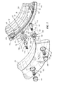
- FIG. 4 is another front view of a portion of the pipe machining apparatus with a portion thereof broken away to show a portion of the bearing assembly of the pipe machining apparatus, in accordance with one embodiment.
- FIG. 5 is cross-sectional view taken along line 5 - 5 in FIG. 4 , in accordance with one embodiment.
- FIG. 6 is a rear perspective view of a portion of the pipe machining apparatus shown in FIG. 2 with exemplary caps exploded from exemplary recesses defined in the pipe machining apparatus, in accordance with one embodiment.
- FIG. 7 is an exploded view of a portion of the pipe machining apparatus shown in FIG. 2 showing two different types of exemplary roller bearings, in accordance with one embodiment.
- FIGS. 1-3 there is shown one exemplary embodiment of a pipe machining apparatus 20 adapted to machine pipes P of varying diameters.
- the apparatus 20 completely cuts through pipes P.
- the apparatus 20 prepares an end of a pipe P for coupling to another pipe.
- the apparatus 20 both completely cuts and prepares a pipe P for coupling to another pipe.
- pipe machining apparatus 20 is formed of two joined-together semicircular sections 24 A, 24 B and includes a frame 28 and a tool carrier 32 .
- the two sections 24 A, 24 B together comprise the frame 28 and the tool carrier 32 such that a first portion of the frame 28 and a first portion of the tool carrier 32 are included in one section 24 A and a second portion of the frame 28 and a second portion of the tool carrier 32 are included in the other section 24 B.
- the frame 28 has a column 36 extending outwardly of the two semicircular sections 24 A, 24 B and houses a pinion gear 40 adapted to couple with a suitable drive motor 44 , such as an air motor with suitable gear reduction means.
- the frame 28 is adapted to couple and be fixed relative to a pipe P, and the tool carrier 32 is rotatable relative to the fixed frame 28 and the pipe P.
- the air motor 44 is adapted to rotate the tool carrier 32 relative to the frame 28 through a gear train in the column 36 .
- the tool carrier 32 has a circular gear rack 56 for meshing with the pinion gear 40 rotatably mounted in column 36 .
- the pinion gear 40 has an opening 60 provided with a polygonal perimeter for receiving a complementary shaped drive head 64 of drive motor 44 . Therefore, it can be seen that drive motor 44 is adapted to rotate tool carrier 32 relative to the frame 28 through a gear train provided by pinion gear 40 in column 36 and circular gear rack 56 on the tool carrier 32 .
- the rotatable tool carrier 32 includes one or more tool supports 48 (two tool supports shown in the illustrated exemplary embodiment), which support tools 52 for performing a cutting or machining operation on the pipe P as the tools 52 rotate circumferentially about the pipe P.
- the machining operation performed by the tool(s) 52 may form a straight edge perpendicular to a longitudinal extent of the pipe P, a bevel on an end of the pipe P that is transverse to the longitudinal extent of the pipe P and at an angle other than ninety degrees, or an edge of a pipe P having any angle.
- the apparatus 20 further includes four adjustable clamp members or coupling members 68 engageable with an exterior of the pipe P and having suitable adjustability to couple and concentrically locate the apparatus 20 to the pipe P.
- a plurality of projections 80 are adjustably movable into and out of a path of an advancement member 84 coupled to each tool support 48 to advance the tool 52 toward the pipe P.
- the apparatus 20 includes a total of two projections 80 for engaging the advancement members 84 , however, the apparatus 20 may include any number of projections 80 .
- Each projection 80 is coupled to a lever 88 that may be actuated by a user to selectively move the projection 80 into and out of the path of the advancement members 84 .
- tool carrier 32 is rotatably mounted on and supported by frame 28 by a bearing assembly 70 including a plurality of roller bearings 72 .
- the roller bearings 72 ride in a circular bearing race 76 defined in the interior of tool carrier 32 .
- the circular bearing race 76 includes an indentation or V-groove defined in an interior bearing surface 92 of the race 76 and a substantially flat exterior bearing surface 96 . Only a pair of small recesses 100 is defined in the exterior bearing surface 96 of the race and encircle the entire exterior bearing surface 96 of the race 76 (described in more detail below).
- the roller bearings 72 comprise two different types of roller bearings.
- a first type includes an adjustable roller bearing 72 A journaled on a shaft 104 and rotatably adjustable in the frame 28 .
- a second type includes a fixed roller bearing 72 B journaled on a shaft 108 that is not adjustable in the frame 28 .
- the roller bearings 72 A, 72 B are disposed around the pipe machining apparatus 20 in an alternating manner (i.e., every other roller bearing is an adjustable roller bearing 72 A).
- the different types of roller bearings 72 A, 72 B may be disposed around the apparatus 20 in any manner, combination, grouping, etc., and all of such possibilities are intended to be within the spirit and scope of the present disclosure.
- each adjustable roller bearing 72 A is individually adjustable to adjust a radial position of the roller bearing 72 A relative to the circular bearing race 76 .
- Each adjustable roller bearing 72 A includes a roller 112 and a shaft 104 with a threaded distal end 116 and an enlarged head 120 at the opposite end.
- the shaft 104 has an eccentric portion 124 immediately inside enlarged head 120 .
- the roller 112 circumscribes eccentric portion 124 of shaft 104 . Therefore, it can be understood that the radial position of each roller 112 relative to bearing race 76 can be changed or adjusted in response to rotational adjustment of shaft 104 .
- each roller 112 rotates about a roller axis 118 and it can be understood that the roller axis 118 can be moved or adjusted relative to the frame 28 in response to rotational adjustment of shaft 104 .
- roller 112 is sandwiched between enlarged head 120 of shaft 104 and a bushing 128 which engages frame 28 .
- the opposite end of shaft 104 is provided with a tool engagement portion or, in the illustrated exemplary embodiment, a hexagonal socket 132 for receiving an appropriate wrench to rotate the shaft 104 and eccentric portion 124 which is effective to adjust the radial position of roller bearing 72 A.
- the threaded distal end 116 including socket 132 , is positioned at and accessible from an exterior of the frame 28 to facilitate adjustment of the roller bearings 72 A from outside the apparatus 20 .
- a lock nut 136 is threaded onto distal end 116 of shaft 104 over a washer 140 . Once the shaft 104 is rotated by a wrench to bring the respective roller 112 into desired engagement with bearing race 76 , nut 136 is tightened to lock the roller bearing 72 A in the particular radial position of adjustment.
- the lock nuts 136 and the respective distal ends 116 of the shafts 104 of the adjustable roller bearings 72 A are located in recesses 144 defined in frame 28 , which facilitates adjustability of the roller bearings 72 A from an exterior of the pipe machining apparatus 20 and eliminates the need to disassemble the pipe machining apparatus 20 (e.g., disassemble the fixed frame 28 and the tool carrier 32 ) in order to adjust the roller bearings 72 A.
- Caps 148 are positionable in all of the recesses 144 to close off and protect the recesses 144 , the lock nuts 136 , and the threaded ends 116 of the shafts 104 when adjustability is not desired.
- the caps 148 may be coupled to the frame 28 in the recesses 144 in any manner such as, for example, press-fit, threaded, detented, or any other manner.
- each roller 112 includes an outer circular bearing part 152 and an inner hub 156 (see FIG. 7 ).
- Outer bearing part 152 is freely rotatable about hub 156 by means of ball bearings.
- the outer bearing part 152 includes a V-shaped configuration including two angled engagement portions 160 for engaging a complementary shaped V-groove defined in the interior engagement surface 92 of the race 76 .
- the V-shaped outer bearing part 152 provides dual line contact between the roller 112 and the race 76 with the two lines of engagement angled and non-parallel to each other. In the illustrated exemplary embodiment, both lines of contact are transverse to a rotational axis 164 of the tool carrier 32 .
- both lines of contact may be orientated at about a 45 degree angle relative to the rotational axis 164 of the tool carrier 32 .
- the lines of contact may be at any angle relative to the rotational axis 164 of the tool carrier 32 including parallel.
- the hub 156 is press-fit over eccentric portion 124 of shaft 104 and is positioned between enlarged head 120 and bushing 128 when the bearing 72 A is locked in a given position, while outer bearing part 152 is free to rotate and ride along the interior bearing surface 92 of the bearing race 76 .
- the roller 112 and the bearing race 76 are appropriately sized to inhibit the roller 112 of the adjustable bearing 72 A from engaging the exterior bearing surface 96 of the bearing race 76 .
- the exterior bearing surface 96 defines the pair of recesses 100 therein that encircle the entire race 76 .
- the pair of recesses 100 align with the two furthest projecting portions of the V-rollers 112 of the adjustable roller bearings 72 A such that the V-rollers 112 do not contact the exterior engagement surface 96 of the race 76 .
- the adjustable roller bearings 72 A are also adapted to provide a preload between the adjustable roller bearings 72 A and the fixed roller bearings 72 B during assembly of the apparatus 20 .
- the adjustable roller bearings 72 A are adjusted or moved into contact with the interior bearing surface 92 of the race 76 resulting in a force applied by the adjustable roller bearings 72 A, thereby forcing the fixed roller bearings 72 B into engagement with the exterior bearing surface 96 to establish a preload between the adjustable roller bearings 72 A and the fixed roller bearings 72 B.
- each fixed roller bearing 72 B includes a roller 168 and a shaft 108 with a threaded distal end 172 and an enlarged head 176 at the opposite end.
- the shaft 108 has a concentric portion 180 immediately inside enlarged head 176 and the roller 168 circumscribes the concentric portion 180 of shaft 108 .
- the roller 168 is sandwiched between the enlarged head 176 and a washer 184 engaging the frame 28 .
- the threaded distal end 172 of the shaft 108 is threaded into an internally threaded cavity 188 defined in the frame 28 to secure the fixed roller bearing 72 B relative to the frame 28 .
- the roller 168 rotates about a roller axis 170 and, since the roller bearing 72 B is fixed relative to the frame 28 , the roller axis 170 is fixed and does not move relative to the frame 28 .
- each roller 168 includes an outer circular bearing part 192 and an inner hub 196 .
- Outer bearing part 192 is freely rotatable about hub 196 by means of ball bearings.
- the outer bearing part 192 includes a substantially flat engagement portion 200 for engaging the substantially flat exterior engagement surface 96 of the race 76 .
- the substantially flat engagement portion 200 provides a single line contact between the roller 168 and the exterior race 76 .
- the single line contact is substantially parallel to the rotational axis 164 of the tool carrier 32 .
- the single line contact may be transverse to the rotational axis 164 of the tool carrier 32 .
- the hub 196 is press-fit over concentric portion 180 of shaft 108 and is positioned between enlarged head 176 and washer 184 , while outer bearing part 192 is free to rotate and ride along the exterior bearing surface 96 of the bearing race 76 .
- the roller 168 and the bearing race 76 are appropriately sized to inhibit the roller 168 of the fixed bearing 72 B from engaging the interior bearing surface 92 of the bearing race 76 .
- the fixed bearings 72 B provides radial support to the tool carrier 32 , assist with establishing location of the tool carrier 32 , and assists with proper engagement and backlash of the drive pinion gear 40 to the gear rack 56 .
- the tool 52 applies a machining force to a pipe P, which may result in outward radial forces and axial forces on the tool support(s) 48 and the tool carrier 32 .
- These machining forces result in forcing the interior engagement surface 92 of the race 76 more into or against the roller 112 of the adjustable roller bearing 72 A, which ensures a reliable and adequate radial engagement between the roller bearing 72 A and the race 76 .
- these machining forces may result in forcing the tool carrier 32 in an axial direction, which results in forcing the interior engagement surface 92 of the race 76 into or against the two lines of contact provided by the two angled engagement portions 160 of the roller bearing 72 A.
- roller bearings 72 A assist with maintaining proper operation and movement of the tool carrier 32 relative to the fixed frame 28 , and additionally may assist with reducing chatter during operation of the pipe machining apparatus 20 .
- the roller bearings 72 A provide both radial and axial support during the machining operation of the pipe cutting apparatus 20 .
- Conventional pipe machining apparatuses operate in a different manner.
- conventional pipe machining apparatuses include roller bearings within a race, however, a machining force realized by a tool machining a pipe forces the interior engagement surface of the race away from the roller bearings, thereby providing a looser, less reliable, and potentially inadequate engagement between the roller bearing and the race.
Landscapes
- Engineering & Computer Science (AREA)
- Mechanical Engineering (AREA)
- General Engineering & Computer Science (AREA)
- Turning (AREA)
- Rolling Contact Bearings (AREA)
- Rolls And Other Rotary Bodies (AREA)
Abstract
Description
Claims (8)
Priority Applications (6)
| Application Number | Priority Date | Filing Date | Title |
|---|---|---|---|
| US13/796,211 US9638245B2 (en) | 2012-10-04 | 2013-03-12 | Bearing assembly for a pipe machining apparatus |
| EP13779982.1A EP2903765B1 (en) | 2012-10-04 | 2013-10-02 | Bearing assembly for a pipe machining apparatus |
| CN201380059752.9A CN104797364B (en) | 2012-10-04 | 2013-10-02 | Bearing assembly for pipe machining equipment |
| PCT/US2013/062999 WO2014055610A1 (en) | 2012-10-04 | 2013-10-02 | Bearing assembly for a pipe machining apparatus |
| US14/533,714 US20150053060A1 (en) | 2012-10-04 | 2014-11-05 | Bearing assembly for a pipe machining apparatus |
| US15/468,365 US10436245B2 (en) | 2012-10-04 | 2017-03-24 | Bearing assembly for a pipe machining apparatus |
Applications Claiming Priority (2)
| Application Number | Priority Date | Filing Date | Title |
|---|---|---|---|
| US201261709531P | 2012-10-04 | 2012-10-04 | |
| US13/796,211 US9638245B2 (en) | 2012-10-04 | 2013-03-12 | Bearing assembly for a pipe machining apparatus |
Related Child Applications (2)
| Application Number | Title | Priority Date | Filing Date |
|---|---|---|---|
| US14/533,714 Continuation-In-Part US20150053060A1 (en) | 2012-10-04 | 2014-11-05 | Bearing assembly for a pipe machining apparatus |
| US15/468,365 Division US10436245B2 (en) | 2012-10-04 | 2017-03-24 | Bearing assembly for a pipe machining apparatus |
Publications (2)
| Publication Number | Publication Date |
|---|---|
| US20140096663A1 US20140096663A1 (en) | 2014-04-10 |
| US9638245B2 true US9638245B2 (en) | 2017-05-02 |
Family
ID=50431699
Family Applications (2)
| Application Number | Title | Priority Date | Filing Date |
|---|---|---|---|
| US13/796,211 Active 2035-02-27 US9638245B2 (en) | 2012-10-04 | 2013-03-12 | Bearing assembly for a pipe machining apparatus |
| US15/468,365 Active 2033-03-14 US10436245B2 (en) | 2012-10-04 | 2017-03-24 | Bearing assembly for a pipe machining apparatus |
Family Applications After (1)
| Application Number | Title | Priority Date | Filing Date |
|---|---|---|---|
| US15/468,365 Active 2033-03-14 US10436245B2 (en) | 2012-10-04 | 2017-03-24 | Bearing assembly for a pipe machining apparatus |
Country Status (4)
| Country | Link |
|---|---|
| US (2) | US9638245B2 (en) |
| EP (1) | EP2903765B1 (en) |
| CN (1) | CN104797364B (en) |
| WO (1) | WO2014055610A1 (en) |
Cited By (1)
| Publication number | Priority date | Publication date | Assignee | Title |
|---|---|---|---|---|
| US10675692B2 (en) | 2016-08-25 | 2020-06-09 | Illinois Tool Works Inc. | Systems, apparatuses and methods of machining pipes and/or pipe flanges |
Families Citing this family (19)
| Publication number | Priority date | Publication date | Assignee | Title |
|---|---|---|---|---|
| US9475160B2 (en) | 2012-10-04 | 2016-10-25 | Illinois Tool Works Inc. | Coupling members and pipe machining apparatuses including coupling members |
| US10710177B2 (en) | 2012-10-04 | 2020-07-14 | Illinois Tool Works Inc | Coupling members for pipe machining apparatuses |
| US10434584B2 (en) | 2012-10-04 | 2019-10-08 | Illinois Tool Works Inc. | Coupling members for pipe machining apparatuses |
| US9638245B2 (en) | 2012-10-04 | 2017-05-02 | Illinois Tool Works Inc. | Bearing assembly for a pipe machining apparatus |
| US9050669B2 (en) | 2012-10-04 | 2015-06-09 | Illinois Tool Works Inc. | Rapidly retractable tool support for a pipe machining apparatus |
| US9610636B2 (en) | 2013-01-09 | 2017-04-04 | Illinois Tool Works Inc. | Pipe machining apparatuses and methods of operating the same |
| US9278417B2 (en) * | 2013-01-09 | 2016-03-08 | Illinois Tool Works Inc. | Pipe machining apparatuses and methods of operating the same |
| US20160121406A1 (en) * | 2014-10-29 | 2016-05-05 | Illinois Tool Works Inc. | Interchangeable cutting inserts and methods associated with the same |
| WO2016073165A1 (en) * | 2014-11-05 | 2016-05-12 | Illinois Tool Works Inc. | Bearing assembly for a pipe machining apparatus |
| US10065246B2 (en) | 2015-04-13 | 2018-09-04 | Illinois Tool Works Inc. | Laser line generator tool for a pipe machining apparatus |
| WO2017027776A1 (en) | 2015-08-12 | 2017-02-16 | Illinois Tool Works Inc. | Crash resistant trip for a pipe for a machining apparatus |
| CN107813009A (en) * | 2016-09-13 | 2018-03-20 | 中国石油天然气管道第二工程公司 | A kind of rotating mechanism of pipeline cold cut cutting mill |
| CN106862591A (en) * | 2017-03-13 | 2017-06-20 | 上海电气电站设备有限公司 | Macrotype axes series parts axle journal turning equipment and turning process |
| WO2019060751A1 (en) | 2017-09-25 | 2019-03-28 | Johnson Controls Technology Company | Compact variable geometry diffuser mechanism |
| EP3807046B1 (en) | 2018-06-18 | 2023-08-02 | Illinois Tool Works INC. | Pipe machining system for positioning pipe machining apparatus in three-dimensional coordinate system |
| CN111120789B (en) * | 2018-10-31 | 2022-08-09 | 佳能株式会社 | Rotating mechanism and equipment comprising same |
| CN112589184B (en) * | 2020-12-23 | 2022-04-05 | 河南易沃克工业设备有限公司 | Rotary groove cutting device |
| US12358062B2 (en) | 2021-07-09 | 2025-07-15 | Illinois Tool Works Inc. | Assembly for positioning pipe machining apparatus for miter cutting |
| CN113523317B (en) * | 2021-08-02 | 2022-06-10 | 三门核电有限公司 | Cleaning device and cleaning method for large-scale shielding main pump sealing ring |
Citations (85)
| Publication number | Priority date | Publication date | Assignee | Title |
|---|---|---|---|---|
| US1140208A (en) | 1914-11-30 | 1915-05-18 | George Benjamin Taylor | Machine for turning and cutting off pieces from a bar or tube. |
| US1886082A (en) | 1930-04-08 | 1932-11-01 | Great Lakes Aircraft Corp | Radius forming fixture |
| US2358741A (en) | 1942-09-11 | 1944-09-19 | Shelby Peter | Automatic flat - bottom countersinking attachment for milling machines |
| US2364963A (en) | 1943-04-20 | 1944-12-12 | H C Price Company | Pipe beveling machine |
| US2635270A (en) | 1948-07-06 | 1953-04-21 | Robert A J Dawson | Tool carriage ring for pipe cleaning machines |
| DE900042C (en) | 1941-02-20 | 1953-12-17 | August Thyssen Huette Akt Ges | Circumferential cutter head for peeling metallic cylindrical workpieces |
| US2798390A (en) | 1953-07-27 | 1957-07-09 | Porto Knurling Tools Inc | Knurling tools for external cylindrical surfaces |
| US2931659A (en) | 1958-02-12 | 1960-04-05 | Portage Double Quick Inc | Quick change tool holder |
| US2968375A (en) | 1958-07-23 | 1961-01-17 | Gen Motors Corp | Machine rail steel plug |
| US3253336A (en) | 1963-10-17 | 1966-05-31 | Brown Oil Tools | Rotary pipe cutting device having pipe clamping means and ratchet feed means for thecutter |
| US3732758A (en) | 1971-03-08 | 1973-05-15 | M Rinaldo | Pipe cutting apparatus |
| US3807047A (en) * | 1972-01-27 | 1974-04-30 | Dnd Corp | Pipe cutting device |
| DE2439852A1 (en) | 1974-08-20 | 1976-03-04 | Compac Cutting Machine Corp | Pipe cutter and end former ring slide - supports automatic tool, has removable lock pins lock pins also engaging toothed rim segments |
| US3942248A (en) * | 1972-01-27 | 1976-03-09 | Dnd Corporation | Pipe cutting device |
| US4112794A (en) * | 1977-09-06 | 1978-09-12 | Burr Oak Tool & Gauge Company | Tube cutter with phase changer |
| US4318391A (en) | 1980-06-02 | 1982-03-09 | The E. H. Wachs Company | Pile-cutting machine and method of cutting multi-sided piles |
| US4366994A (en) * | 1979-11-02 | 1983-01-04 | Hitachi, Ltd. | Damped bearing device |
| US4397487A (en) | 1980-08-28 | 1983-08-09 | Milton Guttman | Free-wheeling latching system |
| US4411178A (en) * | 1981-06-04 | 1983-10-25 | Power Cutting Incorporated | Pipe end preparation machine |
| US4421441A (en) | 1980-10-29 | 1983-12-20 | Brother Kogyo Kabushiki Kaisha | Cyclic drilling machine |
| US4483223A (en) | 1983-04-07 | 1984-11-20 | Tri Tool Inc. | Portable lathe |
| US4490909A (en) | 1982-11-26 | 1985-01-01 | The E. H. Wachs Company | Travelling pipe cutter |
| US4493150A (en) * | 1982-11-05 | 1985-01-15 | Garcia Carlos M | Pipe cutter with split ring frame and enclosed feeding means |
| US4543861A (en) | 1984-05-11 | 1985-10-01 | The E. H. Wachs Company | Portable lathe |
| CN85102879A (en) | 1985-04-01 | 1986-01-10 | 大连工学院 | Full automatic hydraulic pipe cutter |
| US4608755A (en) * | 1984-11-13 | 1986-09-02 | Braasch Morris C | Portable pipe cutter |
| US4637285A (en) | 1984-08-06 | 1987-01-20 | Hideo Mizoguchi | Automatic feed device for a facing head |
| US4655108A (en) | 1985-09-16 | 1987-04-07 | The E. H. Wachs Company | Tube-squaring tool and clamping mechanism |
| US4677884A (en) | 1985-04-05 | 1987-07-07 | The E. H. Wachs Company | Portable end prep lathe |
| DE3603618C1 (en) | 1986-02-06 | 1987-10-01 | Friedhelm Hake | Clamping device for use on machine tools |
| US4739685A (en) | 1987-01-12 | 1988-04-26 | Ricci Donato L | Split frame portable machining lathe |
| US4762038A (en) | 1986-10-14 | 1988-08-09 | The E. H. Wachs Company | Pipe machining apparatus |
| US4770074A (en) | 1986-08-29 | 1988-09-13 | Westinghouse Electric Corp. | Multi-function pipe machining apparatus |
| CN87101953A (en) | 1987-03-13 | 1988-09-21 | 特赖器械公司 | Bearing arrangement for portable lathe |
| US4791842A (en) | 1986-10-14 | 1988-12-20 | E. H. Wachs Company | Pipe machining apparatus |
| US4813314A (en) * | 1986-08-29 | 1989-03-21 | Westinghouse Electric Corp. | Multi-function pipe machining apparatus |
| US4829860A (en) * | 1987-04-03 | 1989-05-16 | Tri Tool Inc. | Segmented sliding bearing arrangement for portable lathe |
| US4880340A (en) | 1987-07-22 | 1989-11-14 | Asada Kabushiki Kaisha | Screw cutter die head |
| US4939964A (en) | 1988-09-16 | 1990-07-10 | Ricci Donato L | Low-clearance pipe lathe |
| FR2641487A1 (en) | 1989-01-10 | 1990-07-13 | Barras Provence | Carrying vehicle with a tool for inspection and/or maintenance of the stud holes of the carrier flange of the head of a vessel or the like |
| US5002440A (en) | 1988-01-21 | 1991-03-26 | Rex Industries Co., Ltd. | Apparatus for automatically stopping operation of cutting machine |
| US5013015A (en) | 1990-06-11 | 1991-05-07 | General Dynamics Corporation | Mechanically actuated swing clamp |
| US5050291A (en) | 1990-05-12 | 1991-09-24 | Gilmore Guy T | Universal tool |
| US5054342A (en) | 1989-05-09 | 1991-10-08 | The E.H. Wachs Company | Pipe machining apparatus |
| GB2242850A (en) | 1989-11-07 | 1991-10-16 | British Gas Plc | Method of and apparatus for cutting a workpiece, particularly a pipe |
| US5070600A (en) | 1990-06-29 | 1991-12-10 | The Babcock & Wilcox Company | Tool positioning assembly |
| CN2109276U (en) | 1991-10-21 | 1992-07-08 | 东北输油管理局 | Double-chain selfmoving electric pipe cutting machine |
| US5199928A (en) | 1992-05-06 | 1993-04-06 | Emerson Electric Co. | Threading machine die head |
| US5361659A (en) * | 1993-04-16 | 1994-11-08 | Crc-Evans Pipeline International, Inc. | Apparatus and method for counterboring a pipe |
| US5368399A (en) | 1993-10-20 | 1994-11-29 | Tri Tool Inc. | Adjustable bearing assembly |
| US5549024A (en) | 1995-01-30 | 1996-08-27 | Ricci; Donato L. | Clamshell pipe lathe having improved bearing arrangement |
| US5557995A (en) * | 1993-04-13 | 1996-09-24 | Wellcutter, Inc. | Radial cutting tools for cutting thick-walled tubular members |
| US5603250A (en) * | 1993-04-13 | 1997-02-18 | Wellcutter, Inc. | Radial cutting tool having indexed pair of bit-subassemblies with simultaneous feed for cutting thick-walled tubes |
| US5609081A (en) * | 1995-03-30 | 1997-03-11 | Lin; Shoei C. | Portable round-tube cutter |
| CN2254385Y (en) | 1995-06-23 | 1997-05-21 | 张勇升 | Pipe cutting groove machine |
| US5660093A (en) * | 1996-01-22 | 1997-08-26 | Ricci; Donato L. | Portable journal turning lathe |
| EP0819501A1 (en) | 1996-07-19 | 1998-01-21 | Kabushiki Kaisha Kosmek | Rotary Clamping apparatus |
| CN2274107Y (en) | 1996-04-01 | 1998-02-11 | 郑祥隆 | Electric bevelling machine for cutting pipe |
| US5775188A (en) * | 1996-02-29 | 1998-07-07 | Climax Portable Machine Tools, Inc. | Apparatus for and method of facing surfaces |
| US5894772A (en) * | 1997-02-18 | 1999-04-20 | Nodar; Felix | Portable pipe machining tool |
| US5941145A (en) * | 1997-11-14 | 1999-08-24 | Tri Tool Inc. | Tube squaring tool |
| US5943927A (en) * | 1997-11-03 | 1999-08-31 | Crc-Evans Pipeline International, Inc. | Apparatus and method for counterboring a pipe |
| US5954462A (en) | 1998-08-12 | 1999-09-21 | Climax Portable Machine Tools, Inc. | Spot facing machine |
| US6065378A (en) | 1998-11-23 | 2000-05-23 | Ricci; Donato L. | Portable journal turning lathe |
| DE10020393A1 (en) | 1999-05-31 | 2001-02-01 | Fischer G Rohrverbindungstech | Pipe cutting device |
| US6227577B1 (en) | 1997-12-25 | 2001-05-08 | Victaulic Co., Of Japan, Ltd. | Housing type pipe coupling |
| US6257110B1 (en) | 2000-02-02 | 2001-07-10 | Donato L. Ricci | Tube saw |
| US6615696B2 (en) * | 2001-12-10 | 2003-09-09 | Donato L. Ricci | Oval manway facing machine |
| US20040035171A1 (en) | 2002-07-11 | 2004-02-26 | Joseph Gormany | Pipe cutting and beveling tool |
| US20040234352A1 (en) | 2003-03-03 | 2004-11-25 | Vanderpol Jerald W. | Cutting and beveling tool |
| US20050132851A1 (en) | 2003-12-17 | 2005-06-23 | Donato L. Ricci | Out of round tool bit holder assembly |
| US7000510B1 (en) * | 2004-10-06 | 2006-02-21 | Donato L. Ricci | Adjustable locator for clamshell lathe |
| US20060207395A1 (en) | 2005-03-16 | 2006-09-21 | Brent Place | Swivel head module for a clamshell lathe |
| US7383758B2 (en) * | 2006-06-14 | 2008-06-10 | D.L. Ricci Corp. | Air-operated end prep machine |
| US20100062887A1 (en) | 2006-05-16 | 2010-03-11 | Iwis Motorsysteme Gmbh & Co. Kg | Tensioning rail or guide with securing means for retaining bolts |
| CN201482987U (en) | 2009-08-07 | 2010-05-26 | 浙江澳太机械制造有限公司 | Groove cutting machine of electric pipe |
| US20100162860A1 (en) | 2008-12-31 | 2010-07-01 | H&S Tool, Inc. | Clamshell lathe |
| DE102009005983A1 (en) | 2009-01-23 | 2010-07-29 | Illinois Tool Works Inc., Glenview | Pipe processing device |
| US20110219920A1 (en) | 2010-03-15 | 2011-09-15 | Illinois Tool Works Inc. | Rotating Pipe Machining Device |
| WO2012071419A1 (en) | 2010-11-24 | 2012-05-31 | Actuant Corporation | Portable machining apparatus tool module |
| US8250953B2 (en) * | 2008-12-31 | 2012-08-28 | H&S Tool, Inc. | Tripper assembly for a clamshell lathe |
| WO2014055610A1 (en) | 2012-10-04 | 2014-04-10 | Illinois Tool Works Inc. | Bearing assembly for a pipe machining apparatus |
| US20140190327A1 (en) | 2013-01-09 | 2014-07-10 | Illinois Tool Works Inc. | Pipe machining apparatuses and methods of operating the same |
| WO2014109910A1 (en) | 2013-01-14 | 2014-07-17 | Illinois Tool Works Inc. | Pipe machining apparatus and method of operating the same |
| US9050669B2 (en) * | 2012-10-04 | 2015-06-09 | Illinois Tool Works Inc. | Rapidly retractable tool support for a pipe machining apparatus |
Family Cites Families (8)
| Publication number | Priority date | Publication date | Assignee | Title |
|---|---|---|---|---|
| US3431646A (en) | 1967-03-24 | 1969-03-11 | James L Young | Pipe cutting and beveling apparatus |
| US4289430A (en) | 1979-03-14 | 1981-09-15 | Fairfield Machine Company | Method and apparatus for simultaneously boring and turning upset pipe end |
| US4754672A (en) | 1987-04-03 | 1988-07-05 | Tri Tool Inc | Segmented sliding bearing arrangement for portable lathe |
| DE4240637C1 (en) | 1992-12-03 | 1994-06-23 | Ant Nachrichtentech | Circuit board clamp device |
| CN1424155A (en) | 2001-12-12 | 2003-06-18 | 陆秀成 | Special pipe cutting and notching tool |
| CN2761329Y (en) | 2005-01-25 | 2006-03-01 | 上海塞沃机电设备有限公司 | Closed tube cutting jevelling machine |
| US7793574B2 (en) | 2005-08-22 | 2010-09-14 | Climax Portable Machine Tools Inc. | Machine tool |
| US20090191040A1 (en) | 2007-05-09 | 2009-07-30 | Ming-Hsun Liu | Handling Device |
-
2013
- 2013-03-12 US US13/796,211 patent/US9638245B2/en active Active
- 2013-10-02 WO PCT/US2013/062999 patent/WO2014055610A1/en not_active Ceased
- 2013-10-02 EP EP13779982.1A patent/EP2903765B1/en not_active Not-in-force
- 2013-10-02 CN CN201380059752.9A patent/CN104797364B/en active Active
-
2017
- 2017-03-24 US US15/468,365 patent/US10436245B2/en active Active
Patent Citations (87)
| Publication number | Priority date | Publication date | Assignee | Title |
|---|---|---|---|---|
| US1140208A (en) | 1914-11-30 | 1915-05-18 | George Benjamin Taylor | Machine for turning and cutting off pieces from a bar or tube. |
| US1886082A (en) | 1930-04-08 | 1932-11-01 | Great Lakes Aircraft Corp | Radius forming fixture |
| DE900042C (en) | 1941-02-20 | 1953-12-17 | August Thyssen Huette Akt Ges | Circumferential cutter head for peeling metallic cylindrical workpieces |
| US2358741A (en) | 1942-09-11 | 1944-09-19 | Shelby Peter | Automatic flat - bottom countersinking attachment for milling machines |
| US2364963A (en) | 1943-04-20 | 1944-12-12 | H C Price Company | Pipe beveling machine |
| US2635270A (en) | 1948-07-06 | 1953-04-21 | Robert A J Dawson | Tool carriage ring for pipe cleaning machines |
| US2798390A (en) | 1953-07-27 | 1957-07-09 | Porto Knurling Tools Inc | Knurling tools for external cylindrical surfaces |
| US2931659A (en) | 1958-02-12 | 1960-04-05 | Portage Double Quick Inc | Quick change tool holder |
| US2968375A (en) | 1958-07-23 | 1961-01-17 | Gen Motors Corp | Machine rail steel plug |
| US3253336A (en) | 1963-10-17 | 1966-05-31 | Brown Oil Tools | Rotary pipe cutting device having pipe clamping means and ratchet feed means for thecutter |
| US3732758A (en) | 1971-03-08 | 1973-05-15 | M Rinaldo | Pipe cutting apparatus |
| US3807047A (en) * | 1972-01-27 | 1974-04-30 | Dnd Corp | Pipe cutting device |
| US3942248A (en) * | 1972-01-27 | 1976-03-09 | Dnd Corporation | Pipe cutting device |
| DE2439852A1 (en) | 1974-08-20 | 1976-03-04 | Compac Cutting Machine Corp | Pipe cutter and end former ring slide - supports automatic tool, has removable lock pins lock pins also engaging toothed rim segments |
| US4112794A (en) * | 1977-09-06 | 1978-09-12 | Burr Oak Tool & Gauge Company | Tube cutter with phase changer |
| US4366994A (en) * | 1979-11-02 | 1983-01-04 | Hitachi, Ltd. | Damped bearing device |
| US4318391A (en) | 1980-06-02 | 1982-03-09 | The E. H. Wachs Company | Pile-cutting machine and method of cutting multi-sided piles |
| US4397487A (en) | 1980-08-28 | 1983-08-09 | Milton Guttman | Free-wheeling latching system |
| US4421441A (en) | 1980-10-29 | 1983-12-20 | Brother Kogyo Kabushiki Kaisha | Cyclic drilling machine |
| US4411178A (en) * | 1981-06-04 | 1983-10-25 | Power Cutting Incorporated | Pipe end preparation machine |
| US4493150A (en) * | 1982-11-05 | 1985-01-15 | Garcia Carlos M | Pipe cutter with split ring frame and enclosed feeding means |
| US4490909A (en) | 1982-11-26 | 1985-01-01 | The E. H. Wachs Company | Travelling pipe cutter |
| US4483223A (en) | 1983-04-07 | 1984-11-20 | Tri Tool Inc. | Portable lathe |
| US4543861A (en) | 1984-05-11 | 1985-10-01 | The E. H. Wachs Company | Portable lathe |
| US4637285A (en) | 1984-08-06 | 1987-01-20 | Hideo Mizoguchi | Automatic feed device for a facing head |
| US4608755A (en) * | 1984-11-13 | 1986-09-02 | Braasch Morris C | Portable pipe cutter |
| CN85102879A (en) | 1985-04-01 | 1986-01-10 | 大连工学院 | Full automatic hydraulic pipe cutter |
| US4677884A (en) | 1985-04-05 | 1987-07-07 | The E. H. Wachs Company | Portable end prep lathe |
| US4655108A (en) | 1985-09-16 | 1987-04-07 | The E. H. Wachs Company | Tube-squaring tool and clamping mechanism |
| DE3603618C1 (en) | 1986-02-06 | 1987-10-01 | Friedhelm Hake | Clamping device for use on machine tools |
| US4813314A (en) * | 1986-08-29 | 1989-03-21 | Westinghouse Electric Corp. | Multi-function pipe machining apparatus |
| US4770074A (en) | 1986-08-29 | 1988-09-13 | Westinghouse Electric Corp. | Multi-function pipe machining apparatus |
| US4762038A (en) | 1986-10-14 | 1988-08-09 | The E. H. Wachs Company | Pipe machining apparatus |
| US4791842A (en) | 1986-10-14 | 1988-12-20 | E. H. Wachs Company | Pipe machining apparatus |
| US4739685A (en) | 1987-01-12 | 1988-04-26 | Ricci Donato L | Split frame portable machining lathe |
| CN87101953A (en) | 1987-03-13 | 1988-09-21 | 特赖器械公司 | Bearing arrangement for portable lathe |
| US4829860A (en) * | 1987-04-03 | 1989-05-16 | Tri Tool Inc. | Segmented sliding bearing arrangement for portable lathe |
| US4880340A (en) | 1987-07-22 | 1989-11-14 | Asada Kabushiki Kaisha | Screw cutter die head |
| US5002440A (en) | 1988-01-21 | 1991-03-26 | Rex Industries Co., Ltd. | Apparatus for automatically stopping operation of cutting machine |
| US4939964A (en) | 1988-09-16 | 1990-07-10 | Ricci Donato L | Low-clearance pipe lathe |
| FR2641487A1 (en) | 1989-01-10 | 1990-07-13 | Barras Provence | Carrying vehicle with a tool for inspection and/or maintenance of the stud holes of the carrier flange of the head of a vessel or the like |
| US5054342A (en) | 1989-05-09 | 1991-10-08 | The E.H. Wachs Company | Pipe machining apparatus |
| GB2242850A (en) | 1989-11-07 | 1991-10-16 | British Gas Plc | Method of and apparatus for cutting a workpiece, particularly a pipe |
| US5050291A (en) | 1990-05-12 | 1991-09-24 | Gilmore Guy T | Universal tool |
| US5013015A (en) | 1990-06-11 | 1991-05-07 | General Dynamics Corporation | Mechanically actuated swing clamp |
| US5070600A (en) | 1990-06-29 | 1991-12-10 | The Babcock & Wilcox Company | Tool positioning assembly |
| CN2109276U (en) | 1991-10-21 | 1992-07-08 | 东北输油管理局 | Double-chain selfmoving electric pipe cutting machine |
| US5199928A (en) | 1992-05-06 | 1993-04-06 | Emerson Electric Co. | Threading machine die head |
| US5557995A (en) * | 1993-04-13 | 1996-09-24 | Wellcutter, Inc. | Radial cutting tools for cutting thick-walled tubular members |
| US5603250A (en) * | 1993-04-13 | 1997-02-18 | Wellcutter, Inc. | Radial cutting tool having indexed pair of bit-subassemblies with simultaneous feed for cutting thick-walled tubes |
| US5361659A (en) * | 1993-04-16 | 1994-11-08 | Crc-Evans Pipeline International, Inc. | Apparatus and method for counterboring a pipe |
| US5368399A (en) | 1993-10-20 | 1994-11-29 | Tri Tool Inc. | Adjustable bearing assembly |
| US5549024A (en) | 1995-01-30 | 1996-08-27 | Ricci; Donato L. | Clamshell pipe lathe having improved bearing arrangement |
| US5609081A (en) * | 1995-03-30 | 1997-03-11 | Lin; Shoei C. | Portable round-tube cutter |
| CN2254385Y (en) | 1995-06-23 | 1997-05-21 | 张勇升 | Pipe cutting groove machine |
| US5660093A (en) * | 1996-01-22 | 1997-08-26 | Ricci; Donato L. | Portable journal turning lathe |
| US5775188A (en) * | 1996-02-29 | 1998-07-07 | Climax Portable Machine Tools, Inc. | Apparatus for and method of facing surfaces |
| CN2274107Y (en) | 1996-04-01 | 1998-02-11 | 郑祥隆 | Electric bevelling machine for cutting pipe |
| EP0819501A1 (en) | 1996-07-19 | 1998-01-21 | Kabushiki Kaisha Kosmek | Rotary Clamping apparatus |
| US5894772A (en) * | 1997-02-18 | 1999-04-20 | Nodar; Felix | Portable pipe machining tool |
| US5943927A (en) * | 1997-11-03 | 1999-08-31 | Crc-Evans Pipeline International, Inc. | Apparatus and method for counterboring a pipe |
| US5941145A (en) * | 1997-11-14 | 1999-08-24 | Tri Tool Inc. | Tube squaring tool |
| US6227577B1 (en) | 1997-12-25 | 2001-05-08 | Victaulic Co., Of Japan, Ltd. | Housing type pipe coupling |
| US5954462A (en) | 1998-08-12 | 1999-09-21 | Climax Portable Machine Tools, Inc. | Spot facing machine |
| US6065378A (en) | 1998-11-23 | 2000-05-23 | Ricci; Donato L. | Portable journal turning lathe |
| DE10020393A1 (en) | 1999-05-31 | 2001-02-01 | Fischer G Rohrverbindungstech | Pipe cutting device |
| US6257110B1 (en) | 2000-02-02 | 2001-07-10 | Donato L. Ricci | Tube saw |
| US6615696B2 (en) * | 2001-12-10 | 2003-09-09 | Donato L. Ricci | Oval manway facing machine |
| US20040035171A1 (en) | 2002-07-11 | 2004-02-26 | Joseph Gormany | Pipe cutting and beveling tool |
| US20040234352A1 (en) | 2003-03-03 | 2004-11-25 | Vanderpol Jerald W. | Cutting and beveling tool |
| US20050132851A1 (en) | 2003-12-17 | 2005-06-23 | Donato L. Ricci | Out of round tool bit holder assembly |
| US7000510B1 (en) * | 2004-10-06 | 2006-02-21 | Donato L. Ricci | Adjustable locator for clamshell lathe |
| US20060207395A1 (en) | 2005-03-16 | 2006-09-21 | Brent Place | Swivel head module for a clamshell lathe |
| US20100062887A1 (en) | 2006-05-16 | 2010-03-11 | Iwis Motorsysteme Gmbh & Co. Kg | Tensioning rail or guide with securing means for retaining bolts |
| US7383758B2 (en) * | 2006-06-14 | 2008-06-10 | D.L. Ricci Corp. | Air-operated end prep machine |
| US20100162860A1 (en) | 2008-12-31 | 2010-07-01 | H&S Tool, Inc. | Clamshell lathe |
| WO2010077349A1 (en) | 2008-12-31 | 2010-07-08 | H&S Tool, Inc. | Clamshell lathe |
| US8250953B2 (en) * | 2008-12-31 | 2012-08-28 | H&S Tool, Inc. | Tripper assembly for a clamshell lathe |
| DE102009005983A1 (en) | 2009-01-23 | 2010-07-29 | Illinois Tool Works Inc., Glenview | Pipe processing device |
| CN201482987U (en) | 2009-08-07 | 2010-05-26 | 浙江澳太机械制造有限公司 | Groove cutting machine of electric pipe |
| US20110219920A1 (en) | 2010-03-15 | 2011-09-15 | Illinois Tool Works Inc. | Rotating Pipe Machining Device |
| US8534170B2 (en) * | 2010-03-15 | 2013-09-17 | Illinois Tool Works Inc. | Rotating pipe machining device |
| WO2012071419A1 (en) | 2010-11-24 | 2012-05-31 | Actuant Corporation | Portable machining apparatus tool module |
| WO2014055610A1 (en) | 2012-10-04 | 2014-04-10 | Illinois Tool Works Inc. | Bearing assembly for a pipe machining apparatus |
| US9050669B2 (en) * | 2012-10-04 | 2015-06-09 | Illinois Tool Works Inc. | Rapidly retractable tool support for a pipe machining apparatus |
| US20140190327A1 (en) | 2013-01-09 | 2014-07-10 | Illinois Tool Works Inc. | Pipe machining apparatuses and methods of operating the same |
| WO2014109910A1 (en) | 2013-01-14 | 2014-07-17 | Illinois Tool Works Inc. | Pipe machining apparatus and method of operating the same |
Non-Patent Citations (8)
| Title |
|---|
| HST2121, "H&S Tool Clamshell.mpg," Dec. 22, 2009, Published on YouTube, https://www.youtube.com/watch?v=Okfh-ODTj-8. |
| International Search Report and Written Opinion for International Patent Application No. PCT/US2013/063023 dated Jun. 2, 2014, 16 pages. |
| International Search Report and Written Opinion for PCT/US2013/062987 dated Feb. 20, 2014, 11 pages. |
| International Search Report and Written Opinion for PCT/US2013/062999 dated Jan. 29, 2014, 12 pages. |
| International Search Report and Written Opinion for PCT/US2013/063007, dated Jan. 22, 2014, 14 pages. |
| International Search Report and Written Opinion for PCT/US2015/056006 dated Mar. 31, 2016, 17 pages. |
| International Search Report and Written Opinion for PCT/US2015/056015 dated Mar. 31, 2016, 19 pages. |
| International Search Report for PCT/US2014/058814, dated Dec. 15, 2014, 3 pages. |
Cited By (2)
| Publication number | Priority date | Publication date | Assignee | Title |
|---|---|---|---|---|
| US10675692B2 (en) | 2016-08-25 | 2020-06-09 | Illinois Tool Works Inc. | Systems, apparatuses and methods of machining pipes and/or pipe flanges |
| US11471960B2 (en) | 2016-08-25 | 2022-10-18 | Illinois Tool Works Inc. | Systems, apparatuses and methods of machining pipes and/or pipe flanges |
Also Published As
| Publication number | Publication date |
|---|---|
| US20170191525A1 (en) | 2017-07-06 |
| US20140096663A1 (en) | 2014-04-10 |
| WO2014055610A1 (en) | 2014-04-10 |
| US10436245B2 (en) | 2019-10-08 |
| EP2903765B1 (en) | 2018-05-23 |
| CN104797364B (en) | 2018-04-06 |
| EP2903765A1 (en) | 2015-08-12 |
| CN104797364A (en) | 2015-07-22 |
Similar Documents
| Publication | Publication Date | Title |
|---|---|---|
| US9638245B2 (en) | Bearing assembly for a pipe machining apparatus | |
| US20150053060A1 (en) | Bearing assembly for a pipe machining apparatus | |
| US10919097B2 (en) | Rapidly retractable tool support for a pipe machining apparatus | |
| US10092957B2 (en) | Tool feed system for use with a rotating machining device | |
| US10661350B2 (en) | Method of using laser line generator tool of a pipe machining apparatus | |
| US9475160B2 (en) | Coupling members and pipe machining apparatuses including coupling members | |
| US10092959B2 (en) | Portable lathe machine | |
| US10434584B2 (en) | Coupling members for pipe machining apparatuses | |
| WO2016073165A1 (en) | Bearing assembly for a pipe machining apparatus | |
| CA3022280C (en) | Portable lathe machine | |
| HK1226363B (en) | Rotating machining device |
Legal Events
| Date | Code | Title | Description |
|---|---|---|---|
| AS | Assignment |
Owner name: ILLINOIS TOOL WORKS INC., ILLINOIS Free format text: ASSIGNMENT OF ASSIGNORS INTEREST;ASSIGNOR:COAKLEY, ROY C.;REEL/FRAME:029973/0991 Effective date: 20130311 |
|
| STCF | Information on status: patent grant |
Free format text: PATENTED CASE |
|
| MAFP | Maintenance fee payment |
Free format text: PAYMENT OF MAINTENANCE FEE, 4TH YEAR, LARGE ENTITY (ORIGINAL EVENT CODE: M1551); ENTITY STATUS OF PATENT OWNER: LARGE ENTITY Year of fee payment: 4 |
|
| MAFP | Maintenance fee payment |
Free format text: PAYMENT OF MAINTENANCE FEE, 8TH YEAR, LARGE ENTITY (ORIGINAL EVENT CODE: M1552); ENTITY STATUS OF PATENT OWNER: LARGE ENTITY Year of fee payment: 8 |