EP3764477A1 - Kontaktträger für einen steckverbinder - Google Patents
Kontaktträger für einen steckverbinder Download PDFInfo
- Publication number
- EP3764477A1 EP3764477A1 EP20183180.7A EP20183180A EP3764477A1 EP 3764477 A1 EP3764477 A1 EP 3764477A1 EP 20183180 A EP20183180 A EP 20183180A EP 3764477 A1 EP3764477 A1 EP 3764477A1
- Authority
- EP
- European Patent Office
- Prior art keywords
- contact
- carrier
- fixing
- contact carrier
- fixation
- Prior art date
- Legal status (The legal status is an assumption and is not a legal conclusion. Google has not performed a legal analysis and makes no representation as to the accuracy of the status listed.)
- Granted
Links
Images

Classifications
-
- H—ELECTRICITY
- H01—ELECTRIC ELEMENTS
- H01R—ELECTRICALLY-CONDUCTIVE CONNECTIONS; STRUCTURAL ASSOCIATIONS OF A PLURALITY OF MUTUALLY-INSULATED ELECTRICAL CONNECTING ELEMENTS; COUPLING DEVICES; CURRENT COLLECTORS
- H01R13/00—Details of coupling devices of the kinds covered by groups H01R12/70 or H01R24/00 - H01R33/00
- H01R13/40—Securing contact members in or to a base or case; Insulating of contact members
- H01R13/42—Securing in a demountable manner
- H01R13/424—Securing in base or case composed of a plurality of insulating parts having at least one resilient insulating part
-
- H—ELECTRICITY
- H01—ELECTRIC ELEMENTS
- H01R—ELECTRICALLY-CONDUCTIVE CONNECTIONS; STRUCTURAL ASSOCIATIONS OF A PLURALITY OF MUTUALLY-INSULATED ELECTRICAL CONNECTING ELEMENTS; COUPLING DEVICES; CURRENT COLLECTORS
- H01R13/00—Details of coupling devices of the kinds covered by groups H01R12/70 or H01R24/00 - H01R33/00
- H01R13/40—Securing contact members in or to a base or case; Insulating of contact members
- H01R13/42—Securing in a demountable manner
- H01R13/422—Securing in resilient one-piece base or case, e.g. by friction; One-piece base or case formed with resilient locking means
- H01R13/4223—Securing in resilient one-piece base or case, e.g. by friction; One-piece base or case formed with resilient locking means comprising integral flexible contact retaining fingers
-
- H—ELECTRICITY
- H01—ELECTRIC ELEMENTS
- H01R—ELECTRICALLY-CONDUCTIVE CONNECTIONS; STRUCTURAL ASSOCIATIONS OF A PLURALITY OF MUTUALLY-INSULATED ELECTRICAL CONNECTING ELEMENTS; COUPLING DEVICES; CURRENT COLLECTORS
- H01R13/00—Details of coupling devices of the kinds covered by groups H01R12/70 or H01R24/00 - H01R33/00
- H01R13/46—Bases; Cases
- H01R13/502—Bases; Cases composed of different pieces
- H01R13/5025—Bases; Cases composed of different pieces one or more pieces being of resilient material
-
- H—ELECTRICITY
- H01—ELECTRIC ELEMENTS
- H01R—ELECTRICALLY-CONDUCTIVE CONNECTIONS; STRUCTURAL ASSOCIATIONS OF A PLURALITY OF MUTUALLY-INSULATED ELECTRICAL CONNECTING ELEMENTS; COUPLING DEVICES; CURRENT COLLECTORS
- H01R43/00—Apparatus or processes specially adapted for manufacturing, assembling, maintaining, or repairing of line connectors or current collectors or for joining electric conductors
- H01R43/20—Apparatus or processes specially adapted for manufacturing, assembling, maintaining, or repairing of line connectors or current collectors or for joining electric conductors for assembling or disassembling contact members with insulating base, case or sleeve
- H01R43/22—Hand tools
Definitions
- the invention relates to a contact carrier according to the preamble of claim 1 and a connector, in particular an electrical connector, containing at least one contact carrier, according to the preamble of claim 13.
- Such a contact carrier comprises a side wall, a contact fixation which is designed to fix at least one contact element on the contact carrier, and an insertion opening arranged on the side wall for inserting a tool.
- the contact fixation has two sections between which the tool can be inserted.
- the contact fixing is designed to fix a contact element arranged on the contact carrier in a fixing position, and can be moved from the fixing position into a release position in order to detach the contact element from the contact carrier by bringing the tool into operative connection with the contact fixing via the insertion opening.
- Contact carriers are usually also referred to as contact inserts and are used in connectors. Connectors of this type can be used, for example, to connect electrical contacts, but optionally also optical contacts with one another.
- An electrical connector which describes a contact insert which has an opening for inserting a tool and insertion openings for a tool, the insertion openings being located within the housing.
- the connector also includes at least one latching arm that is fastened at two points in the housing.
- the problem on which the invention is based is to provide a contact carrier which enables a fixation with increased retention force for a contact element while being easy to handle for releasing.
- the sections of the contact fixing are accordingly connected to the side wall of the contact carrier at a connection point.
- the sections of the contact fixation are each connected to the side wall at a connection point, the retention force for a contact element attached to the contact carrier can be improved, in particular against a tension load on a conductor connected to the contact element.
- the arrangement of the sections of the contact fixation and the connection to the side wall of the contact carrier via connection points on different sides of the insertion opening of the contact carrier creates a contact fixation according to the mode of action of a parallelogram, which enables a high axial force absorption with at the same time low force for mounting the contact element.
- a load can be better transferred into the contact carrier via the contact fixing if the contact element is subjected to axial tensile stress.
- the contact fixing counteracts a conductor extension and enables an improved fixing of the contact element in its axial position on the contact carrier.
- a V-shaped arrangement of the two sections of the contact fixing can improve the absorption of the conductor pull-out force and prevent the contact fixing from buckling axially.
- the contact element can be designed, for example, as a rotated electrical contact.
- the contact element can also be implemented as an optical contact.
- the insertion opening enables a tool, in particular a screwdriver, to be inserted.
- Each contact fixation is assigned an insertion opening via which a tool can be brought into operative connection with the respective contact fixation.
- the contact carrier has one or more contact openings into which contact elements can be inserted for fixing to the contact carrier.
- Each contact opening is assigned a contact fixing for fixing a contact element received in the respective contact opening, it being conceivable that each contact opening is assigned a separate contact fixing for fixing a contact element in the respective contact opening or one contact fixing is assigned to several contact openings in order to connect several contact elements to fix the contact openings at the same time.
- several contact elements can be fixed to a contact carrier, the contact carrier having any number of contact openings for receiving contact elements can, for example, between two and twenty contact openings for receiving one contact element each.
- the contact fixation consists of (at least) two sections.
- the two sections are connected to one another, for example, at a connection point and, moreover, in each case to a connection point to the side wall of the contact carrier.
- the two sections of the contact fixing are arranged at an acute angle to one another and each extend from the connection point to the associated connection point on the side wall of the contact carrier.
- the contact fixation can for example have a V-shaped, U-shaped, Z-shaped (in this case more than two sections), conical or frustoconical basic shape.
- the contact fixation is set up to fix a contact element received in the contact opening in the fixation position, for example by the contact fixation establishing a form-fitting or non-positive connection with the contact element and thereby fixing the contact element to the contact carrier.
- At least one section of the two sections of the contact fixing can have at least one latching element which is designed to fix the received contact element in the fixing position, in particular to fix it in a form-fitting manner.
- the locking element can be used to produce, for example, a fixation that acts both positively and positively.
- the latching element of the contact fixing is arranged here on the section which faces the contact element when the contact element is received in the associated contact opening.
- the contact fixing can have a latching element, but optionally also several latching elements, in order to fix an associated contact element on a plug connector.
- the contact fixing can be moved from the fixing position into a release position in order to release the at least one contact element arranged on the contact carrier.
- a tool can be brought into operative connection with the contact fixation via the insertion opening so that the contact fixation can be elastically deformed by means of the tool so that the fixation of the associated contact element on the contact carrier is canceled, for example by deflecting a section of the contact fixation carrying a latching element is that the locking element is disengaged from the contact element.
- the tool is inserted through the insertion opening into the tool pocket provided for the tool and formed by the contact fixation and can then be moved in order to bring the contact fixation from the fixation position to the release position and thereby fix the contact element to solve.
- the tool can be introduced with a tip into the insertion opening and above it into the tool pocket of the contact fixation provided for the tool and then tilted in the insertion opening in order to deflect the contact fixation to release a contact element.
- At least one of the sections of the contact fixation is elastically deformable.
- both sections of the contact fixing can be designed in such a way that the contact fixing is elastically deformed overall and can thus be moved between its fixing position and the release position. In the relaxed state, the contact fixing is in the fixing position.
- the contact fixing can be elastically deflected from the fixing position and, after the end of an actuation, automatically returns to its fixing position.
- a stop is arranged on at least one of the sections of the contact fixing, which stop is designed to come into contact with a housing of a plug connector in a supporting manner when the contact fixing is moved out of the fixing position.
- An end position for the contact fixing is defined via the stop so that the contact fixing cannot be deformed beyond the end position, for example in the direction of loosening. In this way, excessive loading on the contact fixing is counteracted in the event of an elastic deformation for releasing a contact element.
- the contact carrier has a contact guide which is designed to guide a contact element when it is attached to the contact carrier and also to support it in the attached position.
- a contact element In the attached position, a contact element can be accommodated between the contact guide on a first side and an associated contact fixation on a second side facing away from the first side (transversely to the axial extension direction of the contact element), the contact element being fixed in its seat on the contact carrier via the contact fixation is.
- the other portion of the contact fixing can be extended at an acute angle to the contact guide.
- Such an essentially V-shaped arrangement of the sections to one another can prevent the contact fixing from buckling when the contact element is subjected to a load due to tension on a conductor connected to the contact element, so that axial tensile forces are effectively and resiliently absorbed by the contact fixing and are transferred to the contact carrier can be derived and thus the contact element is held with a comparatively large holding force on the contact carrier.
- the contact carrier is advantageously formed in one piece, with one or more contact fixings being formed in one piece with the side wall of the contact carrier.
- the sections of each contact fixation are formed in one piece on the side wall, wherein, for example, a latching element can be formed in one piece on one section of the contact fixation and a stop can be integrally formed on another section of the contact fixation.
- the contact carrier can also be designed in several pieces, for example by attaching one or more contact fixings as separate elements to the side wall and connecting them to the side wall.
- the contact carrier is entirely or partially made of plastic.
- the contact carrier can, however, also be formed from another, in particular electrically insulating material, for example ceramic or porcelain.
- a plug connector has a housing and a contact carrier of the type described above, wherein the contact carrier can be connected to the housing in a latching manner, for example.
- the housing can, for example, form a plug-in face for the plug-in connection of the plug connector with an associated mating plug connector.
- the contact carrier can be connected to the housing when the contact elements are attached to the contact carrier in order to position the contact elements on the housing, in particular the plug-in face of the housing.
- a section of each contact fixing of the contact carrier can have a stop which, when the contact carrier is connected to the housing, can come into contact with the housing in a supporting manner when the contact fixing is deflected.
- the stop which can for example be formed on the section of the contact fixation facing away from an associated contact guide, can prevent excessive deflection of the contact fixation, especially when a contact element is detached from the contact carrier, so that damage to the contact fixation when deflected by a tool is counteracted.
- Contact carrier 1 shown in one embodiment serves as a carrier for contact elements 7 and can be attached to a housing 2 of a plug connector 14, for example together with contact elements 7 arranged on contact carrier 1 and lead wires connected to them, in order to complete plug connector 14 in this way as shown in the views Figures 6 to 9 can be seen.
- the connector 14 can be connected to an associated mating connector, for example to connect electrical lines to one another or to connect a line to an associated electrical device.
- the contact carrier 1 has a side wall 6 on which a plurality of contact openings 8 are formed, into which contact elements 7 can be inserted for connection to the contact carrier 1.
- a side wall 6 on which a plurality of contact openings 8 are formed, into which contact elements 7 can be inserted for connection to the contact carrier 1.
- contact elements 7 can be inserted for connection to the contact carrier 1.
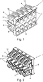
- Fig. 1 As can be seen, in the embodiment shown, two rows of five contact openings 8 each are formed on the side wall 6, so that a total of ten contact elements 7 can be attached to the contact carrier 1.
- contact fixings 9 are arranged, which are connected in one piece to the side wall 6 and serve to fix the contact elements 7 on the contact carrier 1.
- Each contact opening 8 is assigned (precisely) a contact fixing 9, via which a contact element 7 inserted into the contact opening 8 can be fixed on the contact carrier 1.
- the contact fixings 9 are set up to fix contact elements 7 on the contact carrier 1.
- Each contact fixation 9 comprises two sections 91, 92, which are connected to one another at a connection point 61, 62 with the side wall 6 of the contact carrier 1 and at a connection point 12 and between which a tool 3 for acting on the respective contact fixation 9 can be inserted.
- the contact fixings 9 are set up to fix a contact element 7 on the contact carrier 1 in each case in a fixing position. Each contact fixing 9 can be moved from the fixing position into a release position in order to release the respectively assigned contact element 7 from the contact carrier 1 again.
- the contact carrier 1 also has several (here ten) insertion openings 4 arranged on the side wall 6 for inserting a tool 3 each.
- Each contact opening 8 is assigned exactly one insertion opening 4 via which a tool 3 can be brought into operative connection with the contact fixing 9 assigned to the contact opening 8.
- the insertion openings 4 are formed in two rows on the side wall 6, the insertion openings 4 assigned to the lower row of the contact openings 8 being arranged below the lower contact openings 8 and the insertion openings 4 assigned to the upper row of the contact openings 8 above the upper contact openings 8.
- each contact fixing 9 is shaped with its sections 91, 92 to form a substantially V-shaped tool pocket 41.
- Each contact opening 8 is assigned a contact guide 11, which extends essentially parallel to an assigned, opposite section 91 of the assigned contact fixing 9 and thus, together with section 91, creates a receptacle for a contact element 7 inserted into the contact opening 8.
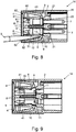
- a contact element 7 can be inserted in an insertion direction E (see for example Figures 4 and 5 ) are inserted into a contact opening 8 and thus arrives in an intermediate position between a contact guide 11 assigned to the contact opening 8 and the section 91 of the assigned contact fixation 9 opposite the contact guide 11 the contact guide 11 protrudes from the section 91 and on which the contact element 7 runs upon insertion in the insertion direction E until the contact element 7 engages with the latching element 5 and is thus positively fixed via the contact fixation 9 on the contact carrier 1, as shown in particular from the Sectional views according to Figures 8 and 9 can be seen.
- the contact elements 7 can be attached to the contact carrier 1 before the contact carrier 1 is connected to the housing 2 of the associated connector 14, so that a preassembled assembly of a contact carrier 1 with contact elements 7 arranged thereon can be mounted on the housing 2 of the connector 14 in order to achieve the To complete connector 14.
- contact elements 7 can also be used at Contact carrier 1 already connected to housing 2 can be attached to contact carrier 1.
- the contact element 7 When a contact element 7 is attached to the contact carrier 1, the contact element 7 runs with a front collar section 70 (see Fig. 8 ) onto the latching element 5 on the section 91 of the contact fixing 9 assigned to the respective contact opening 8. As a result, the contact fixation 9 is deflected with elastic deformation at the sections 91, 92 until the front collar section 70 of the contact element 7 has been moved past the latching element 5 and the latching element 5 thus engages a recess on the between collar sections 70, 71 Contact element 7 can snap, as in particular from Fig. 8 can be seen. The contact element 7 is thus fixed in a latching manner on the contact carrier 1 and held in a form-fitting manner on the contact carrier 1.
- a frictional connection can also be established via the contact fixation 9 with elastic pretension in the direction of the contact guide 11, so that the connection between the contact element 7 and the contact carrier 1 can act positively and / or positively.
- the contact fixation 9 Due to the shape of the contact fixation 9 with the V-shaped mutually arranged sections 91, 92, in particular tensile forces on an associated contact element 7 against the insertion direction E can be absorbed and diverted in a resilient manner. Due to the sections 91, 92 supported at the connection points 61, 62 on the side wall 6 and the V-shaped arrangement of the sections 91, 92 relative to one another, the contact fixing 9 is prevented from buckling when there is an axial load on the contact fixing 9, so that axial tensile forces are effectively supported and can be derived.
- a tool 3 for example a screwdriver, can be inserted with a tip into an insertion opening 4 and brought into operative connection with the associated contact fixation 9, as shown in FIG Fig. 6 in sync with Fig. 7 and 8th can be seen.
- the latching element 5 on the section 91 can be disengaged from the collar sections 70, 71 of the contact element 7, so that the contact element 7 is fixed on the contact carrier 1 is canceled and the contact element 7 can be released from the contact carrier 1 counter to the insertion direction E.
- a stop 10 is formed on the section 92 of each contact fixation 9 that is remote from the respectively assigned contact guide 11 and is used to support the section 92 and thus the contact fixation 9 on the housing 2 when the contact fixation 9 is deflected to release an assigned contact element 7 serves.
- the section 92 can only be deformed until the stop 10 rests against an associated wall of the housing 2, so that excessive deformation of the contact fixation 9 and thus overloading when the contact fixation 9 is deflected is prevented.
- the contact carrier 1 is arranged on the housing 2, protrude in particular from this Fig. 8 It can be seen - contact elements 7 fixed to the contact carrier 1 through openings 21 on a bottom wall 22 of the housing 2 into the area of a plug section 20 of the plug connector 14 formed on the housing 2. Via the plug section 20, the plug connector 14 can be plugged into an assigned mating plug connector in order to provide electrical contact.
- the contact carrier 1 is formed in one piece, so that the contact fixings 9 are formed integrally with the side wall 6.
- Contact openings 8 and contact fixings 9 can in principle be provided in any desired arrangement and number on the contact carrier 1. So shows Fig. 10 For example, an embodiment with a larger number of contact openings 8 and associated contact fixings 9, each contact opening 8 being assigned a contact fixation 9 for fixing a contact element 7 inserted into the contact opening 8, identical to that described above for the embodiment according to FIG Figs. 1 to 9 has been described.
- the contact carrier is formed separately from the housing of the connector and can be connected to the housing in a latching manner.
- a one-piece design is also conceivable in which the contact carrier is formed integrally and in one piece with the housing of the plug connector.
- the contact carrier as well as the housing of the connector can for example be made of plastic and are electrically insulating.
- each contact opening is assigned exactly one contact fixing for fixing exactly one contact element.
Landscapes
- Engineering & Computer Science (AREA)
- Manufacturing & Machinery (AREA)
- Connector Housings Or Holding Contact Members (AREA)
- Manufacturing Of Electrical Connectors (AREA)
Abstract
Description
- Die Erfindung betrifft einen Kontaktträger nach dem Oberbegriff des Anspruchs 1 sowie einen Steckverbinder, insbesondere einen elektrischen Steckverbinder, enthaltend mindestens einen Kontaktträger, nach dem Oberbegriff des Anspruchs 13.
- Ein derartiger Kontaktträger umfasst eine Seitenwandung, eine Kontaktfixierung, die eingerichtet ist, mindestens ein Kontaktelement an dem Kontaktträger zu fixieren, und eine an der Seitenwandung angeordneten Einführöffnung zum Einführen eines Werkzeugs. Die Kontaktfixierung weist zwei Abschnitte auf, zwischen die das Werkzeug einführbar ist. Die Kontaktfixierung ist eingerichtet, in einer Fixierstellung ein an dem Kontaktträger angeordnetes Kontaktelement zu fixieren, und ist aus der Fixierstellung in eine Lösestellung verbringbar, um das Kontaktelement von dem Kontaktträger zu lösen, indem das Werkzeug über die Einführöffnung mit der Kontaktfixierung in Wirkverbindung gebracht wird.
- Kontaktträger werden üblicherweise auch als Kontakteinsätze bezeichnet und werden in Steckverbindern verwendet. Steckverbinder dieser Art können beispielsweise zum Verbinden von elektrischen Kontakten, gegebenenfalls aber auch optischen Kontakten miteinander verwendet werden.
- Aus der
DE 10 2004 002 850 B4 ist ein elektrischer Steckverbinder bekannt, der einen Kontakteinsatz beschreibt, der eine Öffnung zum Einführen eines Werkzeugs und Einstecköffnungen für ein Werkzeug aufweist, wobei die Einstecköffnungen innerhalb des Gehäuses liegen. Der Steckverbinder umfasst zudem mindestens einen Rastarm, der an zwei Stellen im Gehäuse befestigt ist. - Das der Erfindung zugrunde liegende Problem besteht darin, einen Kontaktträger bereitzustellen, der eine Fixierung mit erhöhter Rückhaltekraft für ein Kontaktelement bei einfacher Handhabbarkeit zum Lösen ermöglicht.
- Dieses Problem wird durch einen Kontaktträger mit den Merkmalen des Anspruchs 1 beziehungsweise einem Steckverbinder mit den Merkmalen des Anspruchs 13 gelöst. Weiterbildungen der Erfindung sind in den abhängigen Ansprüchen angegeben.
- Bei einem Kontaktträger sind demnach die Abschnitte der Kontaktfixierung jeweils an einer Verbindungsstelle mit der Seitenwandung des Kontaktträgers verbunden.
- Dadurch, dass die Abschnitte der Kontaktfixierung jeweils an einer Verbindungsstelle mit der Seitenwandung verbunden sind, kann die Rückhaltekraft für ein an den Kontaktträger angesetztes Kontaktelement - insbesondere gegen eine Belastung auf Zug an einem mit dem Kontaktelement verbundenen Leiter - verbessert werden. Die Anordnung der Abschnitte der Kontaktfixierung und die Anbindung an die Seitenwandung des Kontaktträgers über Verbindungsstellen an unterschiedlichen Seiten der Einführöffnung des Kontaktträgers schafft eine Kontaktfixierung nach Wirkweise eines Parallelogramms, das eine hohe axiale Kraftaufnahme bei gleichzeitig kleiner Kraft zur Montage des Kontaktelements ermöglicht.
- Zusätzlich kann eine Last über die Kontaktfixierung besser in den Kontaktträger übertragen werden, wenn das Kontaktelement axial auf Zug belastet wird. Die Kontaktfixierung wirkt einem Leiterauszug entgegen und ermöglicht eine verbesserte Fixierung des Kontaktelements in seiner axialen Position an dem Kontaktträger. Eine beispielsweise V-förmige Anordnung der zwei Abschnitte der Kontaktfixierung kann die Aufnahme der Leiterauszugskraft verbessern und ein axiales Ausknicken der Kontaktfixierung verhindern.
- Das Kontaktelement kann beispielsweise als gedrehter elektrischer Kontakt ausgebildet sein. Das Kontaktelement kann aber auch als optischer Kontakt verwirklicht sein.
- Die Einführöffnung ermöglicht das Einführen eines Werkzeugs, insbesondere eines Schraubendrehers. Jeder Kontaktfixierung ist hierbei eine Einführöffnung zugeordnet, über die ein Werkzeug mit der jeweiligen Kontaktfixierung in Wirkverbindung gebracht werden kann.
- In einer Ausgestaltung weist der Kontaktträger eine oder mehrere Kontaktöffnungen auf, in die Kontaktelemente zur Fixierung an dem Kontaktträger eingesteckt werden können. Einer jeden Kontaktöffnung ist hierbei eine Kontaktfixierung zum Fixieren eines in der jeweiligen Kontaktöffnung aufgenommenen Kontaktelements zugeordnet, wobei denkbar ist, dass jeder Kontaktöffnung eine gesonderte Kontaktfixierung zum Fixieren eines Kontaktelements in der jeweiligen Kontaktöffnung zugeordnet ist oder eine Kontaktfixierung mehreren Kontaktöffnungen zugeordnet ist, um mehrere Kontaktelemente in den Kontaktöffnungen gleichzeitig zu fixieren. An einem Kontaktträger können beispielsweise mehrere Kontaktelemente zu fixieren sein, wobei der Kontaktträger eine beliebige Anzahl von Kontaktöffnungen zum Aufnehmen von Kontaktelementen aufweisen kann, beispielsweise zwischen zwei und zwanzig Kontaktöffnungen zum Aufnehmen je eines Kontaktelements.
- Die Kontaktfixierung besteht aus (mindestens) zwei Abschnitten. Die zwei Abschnitte sind beispielsweise an einem Verbindungspunkt miteinander und zudem jeweils an einer Verbindungsstelle mit der Seitenwandung des Kontaktträgers verbunden. In einer Ausgestaltung sind die zwei Abschnitte der Kontaktfixierung unter einem spitzen Winkel zueinander angeordnet und erstrecken sich von dem Verbindungspunkt jeweils bis hin zu der zugeordneten Verbindungsstelle an der Seitenwandung des Kontaktträgers.
- Die Kontaktfixierung kann beispielsweise eine V-förmige, U-förmige, Z-Förmige (mit in diesem Fall mehr als zwei Abschnitten), kegelförmige oder kegelstumpfförmige Grundform aufweisen. Die Kontaktfixierung ist dabei eingerichtet, ein in der Kontaktöffnung aufgenommenes Kontaktelement in der Fixierstellung zu fixieren, beispielsweise indem Kontaktfixierung eine formschlüssige oder kraftschlüssige Verbindung mit dem Kontaktelement herstellt und dadurch das Kontaktelement zu dem Kontaktträger festgelegt.
- Mindestens ein Abschnitt der zwei Abschnitte der Kontaktfixierung kann in einer Ausführungsform mindestens ein Rastelement aufweisen, das ausgebildet ist, das aufgenommene Kontaktelement in der Fixierstellung zu fixieren, insbesondere formschlüssig zu fixieren. Durch das Rastelement kann dabei beispielsweise eine sowohl kraftschlüssig als auch formschlüssig wirkende Fixierung hergestellt werden. Das Rastelement der Kontaktfixierung ist hierbei an dem Abschnitt angeordnet, der bei in der zugeordneten Kontaktöffnung aufgenommenem Kontaktelement dem Kontaktelement zugewandt ist. Die Kontaktfixierung kann ein Rastelement, gegebenenfalls aber auch mehrere Rastelemente aufweisen, um ein zugeordnetes Kontaktelement an einem Steckverbinder zu fixieren.
- Die Kontaktfixierung ist aus der Fixierstellung in eine Lösestellung verbringbar ist, um das mindestens eine an dem Kontaktträger angeordnete Kontaktelement zu lösen. Hierzu kann ein Werkzeug über die Einführöffnung mit der Kontaktfixierung in Wirkverbindung gebracht werden, sodass mittels des Werkzeugs die Kontaktfixierung so elastisch verformt werden kann, dass die Fixierung des zugeordneten Kontaktelements an dem Kontaktträger aufgehoben wird, beispielsweise indem ein ein Rastelement tragender Abschnitt der Kontaktfixierung so ausgelenkt wird, dass das Rastelement außer Eingriff von dem Kontaktelement gebracht wird.
- Zum Herstellen der Wirkverbindung mit der Kontaktfixierung wird das Werkzeug über die Einführöffnung in die für das Werkzeug vorgesehene, durch die Kontaktfixierung gebildete Werkzeugtasche eingeführt und kann dann so bewegt werden, um die Kontaktfixierung aus der Fixierstellung in die Lösestellung zu verbringen und dadurch die Fixierung des Kontaktelements zu lösen. Beispielsweise kann das Werkzeug mit einer Spitze in die Einführöffnung und darüber in die für das Werkzeug vorgesehene Werkzeugtasche der Kontaktfixierung eingeführt und sodann in der Einführöffnung verkippt werden, um die Kontaktfixierung zum Lösen eines Kontaktelements auszulenken.
- In einer Ausgestaltung ist zumindest einer der Abschnitte der Kontaktfixierung elastisch verformbar. Beispielsweise können beide Abschnitte der Kontaktfixierung so gestaltet sein, dass die Kontaktfixierung insgesamt elastisch verformt und somit zwischen ihrer Fixierstellung und der Lösestellung bewegt werden kann. In entspanntem Zustand befindet sich die Kontaktfixierung hierbei in der Fixierstellung. Aus der Fixierstellung ist die Kontaktfixierung elastisch auslenkbar und gelangt, nach Beendigung einer Betätigung, selbsttätig zurück in ihre Fixierstellung.
- In einer Ausgestaltung ist an mindestens einem der Abschnitte der Kontaktfixierung ein Anschlag angeordnet, der ausgebildet ist, bei Verbringen der Kontaktfixierung aus der Fixierstellung abstützend mit einem Gehäuse eines Steckverbinders in Anlage zu gelangen. Über den Anschlag wird eine Endstellung für die Kontaktfixierung definiert, sodass die Kontaktfixierung nicht über die Endstellung hinaus zum Beispiel in Richtung eines Lösens verformt werden kann. Auf diese Weise wird einer übermäßigen Belastung an der Kontaktfixierung bei einer elastischen Verformung zum Lösen eines Kontaktelements entgegengewirkt.
- Gemäß einer weiteren Ausgestaltung weist der Kontaktträger eine Kontaktführung auf, die zum Führen eines Kontaktelements beim Ansetzen an den Kontaktträger und zudem zum Abstützen in angesetzter Stellung ausgebildet ist. In angesetzter Stellung kann ein Kontaktelement zwischen der Kontaktführung an einer ersten Seite und einer zugeordneten Kontaktfixierung an einer der ersten Seite (quer zur axialen Erstreckungsrichtung des Kontaktelements) abgewandten, zweiten Seite aufgenommen sein, wobei das Kontaktelement über die Kontaktfixierung in seinem Sitz an dem Kontaktträger fixiert ist.
- Während ein Abschnitt der Kontaktfixierung, der beispielsweise ein Rastelement zum formschlüssigen (und gegebenenfalls auch kraftschlüssigen) Fixieren trägt, in der Fixierstellung im Wesentlichen parallel zur Kontaktführung ausgerichtet ist und somit gemeinsam mit der Kontaktführung einen Sitz für das Kontaktelement an dem Kontaktträger schafft, kann, in einer Ausgestaltung, der andere Abschnitt der Kontaktfixierung unter einem spitzen Winkel zur Kontaktführung erstreckt sein. Durch eine solche, im wesentlichen V-förmige Anordnung der Abschnitte zueinander kann bei einer Belastung an dem Kontaktelement durch Zug an einem mit dem Kontaktelement verbundenen Leiter ein Ausknicken der Kontaktfixierung verhindert sein, sodass axiale Zugkräfte durch die Kontaktfixierung wirkungsvoll und belastbar aufgenommen und in den Kontaktträger abgeleitet werden können und somit das Kontaktelement mit vergleichsweise großer Haltekraft an dem Kontaktträger gehalten ist.
- Vorteilhafterweise ist der Kontaktträger einstückig ausgebildet, wobei ein oder mehrere Kontaktfixierungen einstückig mit der Seitenwandung des Kontaktträgers geformt sind. Die Abschnitte einer jeden Kontaktfixierung sind hierbei einstückig an die Seitenwandung angeformt, wobei beispielsweise an einem Abschnitt der Kontaktfixierung ein Rastelement und an einem anderen Abschnitt der Kontaktfixierung ein Anschlag einstückig geformt sein kann.
- In anderer Ausgestaltung kann der Kontaktträger auch mehrstückig ausgebildet sein, beispielsweise indem ein oder mehrere Kontaktfixierungen als gesonderte Elemente an die Seitenwandung angesetzt und mit der Seitenwandung verbunden sind.
- Der Kontaktträger ist, in einer Ausgestaltung, ganz oder teilweise aus Kunststoff gefertigt. Der Kontaktträger kann jedoch auch aus einem anderen, insbesondere elektrisch isolierenden Material, zum Beispiel Keramik oder Porzellan, gebildet sein.
- Ein Steckverbinder weist ein Gehäuse und einen Kontaktträger der vorangehend beschriebenen Art auf, wobei der Kontaktträger beispielsweise rastend mit dem Gehäuse verbunden sein kann. Das Gehäuse kann hierbei beispielsweise ein Steckgesicht zum steckenden Verbinden des Steckverbinders mit einem zugeordneten Gegensteckverbinder ausbilden.
- Der Kontaktträger kann bei an den Kontaktträger angesetzten Kontaktelementen mit dem Gehäuse verbunden werden, um die Kontaktelemente an dem Gehäuse, insbesondere dem Steckgesicht des Gehäuses, zu positionieren. Durch Verwendung des Kontaktträgers kann somit eine vormontierte Baugruppe geschaffen werden, im Rahmen derer die Kontaktelemente vorpositioniert und an zugeordnete Leitungen angeschlossen sein können, um die vormontierte Baugruppe sodann in einem Arbeitsschritt an das Gehäuse anzusetzen und den Steckverbinder somit zu komplettieren.
- In einer Ausgestaltung kann ein Abschnitt einer jeden Kontaktfixierung des Kontaktträgers einen Anschlag aufweisen, der bei mit dem Gehäuse verbundenem Kontaktträger bei Auslenkung der Kontaktfixierung abstützend mit dem Gehäuse in Anlage gelangen kann. Über den Anschlag, der beispielsweise an dem einer zugeordneten Kontaktführung abgewandten Abschnitt der Kontaktfixierung angeformt sein kann, kann eine übermäßige Auslenkung der Kontaktfixierung insbesondere bei Lösen eines Kontaktelements von dem Kontaktträger verhindert werden, sodass einer Beschädigung an der Kontaktfixierung bei Auslenkung über ein Werkzeug entgegengewirkt ist.
- Der der Erfindung zugrundeliegende Gedanke soll nachfolgend anhand von in den Figuren dargestellten Ausführungsbeispielen näher erläutert werden. Es zeigen:
- Fig. 1
- eine Ansicht eines Kontaktträgers, schräg von vorne;
- Fig. 2
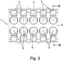
- eine andere Ansicht des Kontaktträgers, schräg von hinten;
- Fig. 3
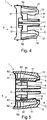
- eine Frontalansicht des Kontaktträgers;
- Fig. 4
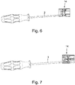
- eine Seitenansicht des Kontaktträgers;
- Fig. 5
- eine Schnittansicht des Kontaktträgers entlang der Linie A-A gemäß
Fig. 3 ; - Fig. 6
- eine Seitenansicht eines einen Kontaktträger aufweisenden Steckverbinders zusammen mit einem Werkzeug;
- Fig. 7
- eine Schnittansicht des Steckverbinders;
- Fig. 8
- eine ausschnittsweise vergrößerte Darstellung der Anordnung gemäß
Fig. 7 ; - Fig. 9
- die vergrößerte Schnittansicht gemäß
Fig. 8 , jedoch ohne Werkzeug und Kontaktelemente; und - Fig. 10
- eine Ansicht einer weiteren Ausführungsbeispiels eines Steckverbinders.
- Ein in
Fig. 1 bis 5 in einem Ausführungsbeispiel dargestellter Kontaktträger 1 dient als Träger für Kontaktelemente 7 und kann, zum Beispiel gemeinsam mit an den Kontaktträger 1 angeordneten Kontaktelementen 7 und daran angeschlossenen Leitungsadern, an ein Gehäuse 2 eines Steckverbinders 14 angesetzt werden, um auf diese Weise den Steckverbinder 14 zu komplettieren, wie dies aus den Ansichten gemäßFig. 6 bis 9 ersichtlich ist. In komplettiertem Zustand kann der Steckverbinder 14 mit einem zugeordneten Gegensteckverbinder verbunden werden, um beispielsweise elektrische Leitungen miteinander zu verbinden oder eine Leitung an ein zugeordnetes elektrisches Gerät anzuschließen. - Der Kontaktträger 1 weist eine Seitenwandung 6 auf, an der eine Mehrzahl von Kontaktöffnungen 8 geformt ist, in die Kontaktelemente 7 zum Verbinden mit dem Kontaktträger 1 eingesetzt werden können. Wie beispielsweise aus
Fig. 1 ersichtlich ist, sind bei dem dargestellten Ausführungsbeispiel an der Seitenwandung 6 zwei Reihen von jeweils fünf Kontaktöffnungen 8 geformt, sodass insgesamt zehn Kontaktelemente 7 an den Kontaktträger 1 angesetzt werden können. - Rückseitig der Seitenwandung 6 sind Kontaktfixierungen 9 angeordnet, die einstückig mit der Seitenwandung 6 verbunden sind und dazu dienen, die Kontaktelemente 7 an dem Kontaktträger 1 zu fixieren. Einer jeden Kontaktöffnung 8 ist hierbei (genau) eine Kontaktfixierung 9 zugeordnet, über die ein jeweils in die Kontaktöffnung 8 eingesetztes Kontaktelement 7 am Kontaktträger 1 fixiert werden kann.
- Die Kontaktfixierungen 9 sind dazu eingerichtet, Kontaktelemente 7 an dem Kontaktträger 1 zu fixieren. Eine jede Kontaktfixierung 9 umfasst zwei Abschnitte 91, 92, die jeweils an einer Verbindungsstelle 61, 62 mit der Seitenwandung 6 des Kontaktträgers 1 und an einer Verbindungsstelle 12 miteinander verbunden sind und zwischen die ein Werkzeug 3 zum Einwirken auf die jeweilige Kontaktfixierung 9 einführbar ist.
- Die Kontaktfixierungen 9 sind dazu eingerichtet, jeweils in einer Fixierstellung ein Kontaktelement 7 an dem Kontaktträger 1 zu fixieren. Eine jede Kontaktfixierung 9 kann hierbei aus der Fixierstellung in eine Lösestellung verbracht werden, um das jeweils zugeordnete Kontaktelement 7 wieder von dem Kontaktträger 1 zu lösen.
- Der Kontaktträger 1 weist zudem mehrere (hier zehn) an der Seitenwandung 6 angeordnete Einführöffnungen 4 für das Einführen je eines Werkzeugs 3 auf.
- Jeder Kontaktöffnung 8 ist hierbei genau eine Einführöffnung 4 zugeordnet, über die ein Werkzeug 3 in Wirkverbindung mit der jeweils der Kontaktöffnung 8 zugeordneten Kontaktfixierung 9 gebracht werden kann. Analog der Anordnung der Kontaktöffnungen 8 sind die Einführöffnungen 4 in zwei Reihen an der Seitenwandung 6 geformt, wobei die der unteren Reihe der Kontaktöffnungen 8 zugeordneten Einführöffnungen 4 unterhalb der unteren Kontaktöffnungen 8 angeordnet sind und die der oberen Reihe der Kontaktöffnungen 8 zugeordneten Einführöffnungen 4 oberhalb der oberen Kontaktöffnungen 8.
- Wie insbesondere aus den Schnittansichten gemäß
Fig. 4 und 5 sowieFig. 8 und 9 ersichtlich ist, ist eine jede Kontaktfixierung 9 mit ihren Abschnitten 91, 92 zur Ausbildung einer im wesentlichen V-förmigen Werkzeugtasche 41 geformt. Einer jeden Kontaktöffnung 8 ist eine Kontaktführung 11 zugeordnet, die sich im Wesentlichen parallel zu einem zugeordneten, gegenüberliegenden Abschnitt 91 der zugeordneten Kontaktfixierung 9 erstreckt und somit gemeinsam mit dem Abschnitt 91 eine Aufnahme für ein in die Kontaktöffnung 8 eingeführtes Kontaktelement 7 schafft. - Zur Anordnung an dem Kontaktträger 1 kann ein Kontaktelement 7 in eine Einführrichtung E (siehe zum Beispiel
Fig. 4 und 5 ) in eine Kontaktöffnung 8 eingesetzt werden und gelangt so in eine Zwischenlage zwischen einer der Kontaktöffnung 8 zugeordneten Kontaktführung 11 und dem der Kontaktführung 11 gegenüberliegenden Abschnitt 91 der zugeordneten Kontaktfixierung 9. An dem Abschnitt 91 der Kontaktfixierung 9 ist ein Rastelement 5 geformt, das in Richtung der Kontaktführung 11 von dem Abschnitt 91 vorsteht und auf das das Kontaktelement 7 bei Einführen in die Einführrichtung E aufläuft, bis das Kontaktelement 7 mit dem Rastelement 5 verrastet und somit formschlüssig über die Kontaktfixierung 9 an dem Kontaktträger 1 fixiert ist, wie dies insbesondere aus den Schnittansichten gemäßFig. 8 und 9 ersichtlich ist. - Das Ansetzen von Kontaktelementen 7 an den Kontaktträger 1 kann vor Verbinden des Kontaktträgers 1 mit dem Gehäuse 2 des zugeordneten Steckverbinders 14 erfolgen, sodass eine vormontierte Baugruppe eines Kontaktträgers 1 mit daran angeordneten Kontaktelementen 7 an dem Gehäuse 2 des Steckverbinders 14 montiert werden kann, um den Steckverbinder 14 zu komplettieren. Alternativ können Kontaktelemente 7 auch bei bereits mit dem Gehäuse 2 verbundenem Kontaktträger 1 an den Kontaktträger 1 angesetzt werden.
- Bei Ansetzen eines Kontaktelements 7 an den Kontaktträger 1 läuft das Kontaktelement 7 mit einem vorderen Bundabschnitt 70 (siehe
Fig. 8 ) auf das Rastelement 5 an dem Abschnitt 91 der der jeweiligen Kontaktöffnung 8 zugeordneten Kontaktfixierung 9 auf. Dadurch wird die Kontaktfixierung 9 unter elastischer Verformung an den Abschnitten 91, 92 ausgelenkt, bis der vordere Bundabschnitt 70 des Kontaktelements 7 an dem Rastelement 5 vorbei bewegt worden ist und das Rastelement 5 somit in Eingriff mit einer zwischen Bundabschnitten 70, 71 geschaffenen Aussparung an dem Kontaktelement 7 schnappen kann, wie dies insbesondere ausFig. 8 ersichtlich ist. Das Kontaktelement 7 ist somit rastend an dem Kontaktträger 1 fixiert und formschlüssig an dem Kontaktträger 1 gehalten. - Zusätzlich oder alternativ kann über die Kontaktfixierung 9 bei elastischer Vorspannung in Richtung der Kontaktführung 11 auch ein Kraftschluss hergestellt werden, sodass die Verbindung zwischen dem Kontaktelement 7 und dem Kontaktträger 1 formschlüssig und/oder kraftschlüssig wirken kann.
- Durch die Formgebung der Kontaktfixierung 9 mit den V-förmig zueinander angeordneten Abschnitten 91, 92 können insbesondere Zugkräfte an einem zugeordneten Kontaktelement 7 entgegen der Einführrichtung E in belastbarer Weise aufgenommen und abgeleitet werden. Aufgrund der an den Verbindungsstellen 61, 62 an der Seitenwandung 6 abgestützten Abschnitte 91, 92 und der V-förmigen Anordnung der Abschnitte 91, 92 zueinander ist ein Ausknicken der Kontaktfixierung 9 bei axialer Belastung an der Kontaktfixierung 9 verhindert, sodass axiale Zugkräfte wirkungsvoll abgestützt und abgeleitet werden können.
- Zum Lösen eines Kontaktelements 7 von dem Kontaktträger 1 kann ein Werkzeug 3, zum Beispiel ein Schraubendreher, mit einer Spitze in einer Einführöffnung 4 eingesteckt und mit der zugeordneten Kontaktfixierung 9 in Wirkverbindung gebracht werden, wie dies aus
Fig. 6 in Zusammenschau mitFig. 7 und8 ersichtlich ist. Durch Verkippen des Werkzeugs 3 in der Einführöffnung 4 und durch auf diese Weise bewirktes Auslenken der Kontaktfixierung 9 kann das Rastelement 5 am Abschnitt 91 außer Eingriff von den Bundabschnitten 70, 71 des Kontaktelements 7 gebracht werden, sodass die Fixierung des Kontaktelements 7 an dem Kontaktträger 1 aufgehoben ist und das Kontaktelement 7 entgegen der Einführrichtung E von dem Kontaktträger 1 gelöst werden kann. - An den Kontaktträger 1 angesetzte Kontaktelemente 7 können somit einfach und komfortabel wieder von dem Kontaktträger 1 entnommen werden.
- Wie insbesondere aus den Ansichten gemäß
Fig. 4 und 5 in Zusammenschau mitFig. 8 und 9 und den perspektivischen Ansichten des Kontaktträgers 1 gemäßFig. 1 und 2 ersichtlich ist, ist an dem von der jeweils zugeordneten Kontaktführung 11 abliegenden Abschnitt 92 einer jeden Kontaktfixierung 9 ein Anschlag 10 geformt, der zur Abstützung des Abschnitts 92 und damit der Kontaktfixierung 9 an dem Gehäuse 2 bei Auslenken der Kontaktfixierung 9 zum Lösen eines zugeordneten Kontaktelements 7 dient. Bei Auslenken einer Kontaktfixierung 9 kann der Abschnitt 92 nur bis zur Anlage des Anschlags 10 an einer zugeordneten Wandung des Gehäuses 2 verformt werden, sodass eine übermäßige Verformung an der Kontaktfixierung 9 und somit eine Überlastung bei Auslenken der Kontaktfixierung 9 verhindert ist. - Ist der Kontaktträger 1 an dem Gehäuse 2 angeordnet, ragen -wie dies insbesondere aus
Fig. 8 ersichtlich ist - an dem Kontaktträger 1 fixierte Kontaktelemente 7 durch Öffnungen 21 an einer Bodenwandung 22 des Gehäuses 2 in den Bereich eines an dem Gehäuse 2 geformten Steckabschnitts 20 des Steckverbinders 14 hinein. Über den Steckabschnitt 20 kann der Steckverbinder 14 mit einem zugeordneten Gegensteckverbinder steckend verbunden werden, um eine elektrische Kontaktierung bereitzustellen. - Bei dem Ausführungsbeispiel gemäß
Fig. 1 bis 9 sind an dem Kontaktträger 1 insgesamt zehn Kontaktöffnungen 8 mit jeweils einer zugeordneten Kontaktfixierung 9 zum Ansetzen von zehn Kontaktelementen 7 geformt. Der Kontaktträger 1 ist hierbei einstückig ausgebildet, sodass die Kontaktfixierungen 9 integral mit der Seitenwandung 6 geformt sind. - Kontaktöffnungen 8 und Kontaktfixierungen 9 können grundsätzlich in beliebiger Anordnung und Anzahl an dem Kontaktträger 1 vorgesehen sein. So zeigt
Fig. 10 beispielsweise ein Ausführungsbeispiel mit einer größeren Anzahl von Kontaktöffnungen 8 und zugeordneten Kontaktfixierungen 9, wobei wiederum jeder Kontaktöffnung 8 eine Kontaktfixierung 9 zum Fixieren eines in die Kontaktöffnung 8 eingesetzten Kontaktelements 7 zugeordnet ist, identisch, wie dies vorangehend für das Ausführungsbeispiel gemäßFig. 1 bis 9 beschrieben worden ist. - Der der Erfindung zugrunde liegende Gedanke ist nicht auf die vorangehend geschilderten Ausführungsbeispiele beschränkt, sondern lässt sich auch in anderer Weise verwirklichen.
- Bei den dargestellten Ausführungsbeispielen ist der Kontaktträger gesondert von dem Gehäuse des Steckverbinders ausgebildet und kann rastend mit dem Gehäuse verbunden werden. Denkbar ist jedoch auch eine einstückige Ausbildung, bei der der Kontaktträger integral und einstückig mit dem Gehäuse des Steckverbinders geformt ist.
- Der Kontaktträger genauso wie das Gehäuse des Steckverbinders können beispielsweise aus Kunststoff gefertigt sein und sind elektrisch isolierend.
- Bei den dargestellten Ausführungsbeispielen ist jeder Kontaktöffnung genau eine Kontaktfixierung zum Fixieren genau eines Kontaktelements zugeordnet. Denkbar ist jedoch auch, über eine Kontaktfixierung mehrere Kontaktelemente an mehreren Kontaktöffnungen zu fixieren, sodass über eine Kontaktfixierung mehrere Kontaktelemente gemeinsam an einem Kontaktträger festgelegt werden können.
-
- 1
- Kontaktträger
- 2
- Gehäuse
- 20
- Steckabschnitt
- 21
- Öffnung
- 22
- Bodenwandung
- 3
- Werkzeug
- 4
- Einführöffnung
- 41
- Werkzeugtasche
- 5
- Rastelement
- 6
- Seitenwandung
- 61, 62
- Verbindungsstelle
- 7
- Kontaktelement
- 70, 71
- Bundabschnitte
- 8
- Kontaktöffnung
- 9
- Kontaktfixierung
- 91, 92
- Abschnitt
- 10
- Anschlag
- 11
- Kontaktführung
- 12
- Verbindungsstelle
- 14
- Steckverbinder
- E
- Einführrichtung
Claims (15)
- Kontaktträger (1) für einen Steckverbinder (14), mit einer Seitenwandung (6), einer Kontaktfixierung (9), die eingerichtet ist, mindestens ein Kontaktelement (7) an dem Kontaktträger (1) zu fixieren, und einer an der Seitenwandung (6) angeordneten Einführöffnung (4) zum Einführen eines Werkzeugs, wobei die Kontaktfixierung (9) zwei Abschnitte (91, 92) aufweist, zwischen die das Werkzeug (3) einführbar ist, und wobei die Kontaktfixierung (9) eingerichtet ist, in einer Fixierstellung ein an dem Kontaktträger (1) angeordnetes Kontaktelement (7) zu fixieren, und aus der Fixierstellung in eine Lösestellung verbringbar ist, um das Kontaktelement (7) von dem Kontaktträger (1) zu lösen, indem das Werkzeug (3) über die Einführöffnung (4) mit der Kontaktfixierung (9) in Wirkverbindung gebracht wird, dadurch gekennzeichnet, dass die Abschnitte (91, 92) der Kontaktfixierung (9) jeweils an einer Verbindungsstelle (61, 62) mit der Seitenwandung (6) des Kontaktträgers (1) verbunden sind.
- Kontaktträger (1) nach Anspruch 1, dadurch gekennzeichnet, dass die Verbindungsstellen (61, 62) der Abschnitte (91, 92) der Kontaktfixierung (9) an unterschiedlichen Seiten der Einführöffnung (4) angeordnet sind.
- Kontaktträger (1) nach Anspruch 1 oder 2, dadurch gekennzeichnet, dass der Kontaktträger (1) eine Kontaktöffnung (8) zum Aufnehmen eines Kontaktelements aufweist, wobei die Kontaktfixierung (9) eingerichtet ist, ein in der Kontaktöffnung (8) aufgenommenes Kontaktelement (7) in der Fixierstellung zu fixieren.
- Kontaktträger (1) nach einem der Ansprüche 1 bis 3, dadurch gekennzeichnet, dass die Kontaktfixierung (9) eingerichtet ist, in der Fixierstellung ein an dem Kontaktträger (1) angeordnetes Kontaktelement (7) formschlüssig oder kraftschlüssig zu fixieren.
- Kontaktträger (1) nach einem der vorhergehenden Ansprüche, dadurch gekennzeichnet, dass ein Abschnitt (91, 92) der zwei Abschnitte (91, 92) der Kontaktfixierung (9) ein Rastelement (5) aufweist, das ausgebildet ist, ein an dem Kontaktträger (1) angeordnetes Kontaktelement (7) in der Fixierstellung zu fixieren.
- Kontaktträger (1) nach einem der vorhergehenden Ansprüche, dadurch gekennzeichnet, dass die zwei Abschnitte (91, 92) der Kontaktfixierung (9) eine V-förmige, U-förmige, kegelförmige oder kegelstumpfförmige Werkzeugtasche (41) bilden.
- Kontaktträger (1) nach einem der vorhergehenden Ansprüche, dadurch gekennzeichnet, dass zumindest einer der zwei Abschnitte (91, 92) der Kontaktfixierung (9) elastisch verformbar ist.
- Kontaktträger (1) nach einem der vorhergehenden Ansprüche, dadurch gekennzeichnet, dass der Kontaktträger (1) eine senkrecht von der Seitenwandung (6) erstreckte Kontaktführung (11) aufweist, die ausgebildet ist, das Kontaktelement (7) zu führen.
- Kontaktträger (1) nach Anspruch 8, dadurch gekennzeichnet, dass einer der zwei Abschnitte (91, 92) der Kontaktfixierung (9) in einem spitzen Winkel zur Kontaktführung (11) erstreckt ist.
- Kontaktträger (1) nach Anspruch 9, dadurch gekennzeichnet, dass der andere der zwei Abschnitte (91, 92) der Kontaktfixierung (9) in der Fixierstellung im Wesentlichen parallel zur Kontaktführung (11) erstreckt ist.
- Kontaktträger (1) nach einem der vorhergehenden Ansprüche, dadurch gekennzeichnet, dass Kontaktträger (1) einstückig ausgebildet ist.
- Kontaktträger (1) nach einem der vorhergehenden Ansprüche, dadurch gekennzeichnet, dass der Kontaktträger (1) zumindest teilweise aus Kunststoff gebildet ist.
- Steckverbinder (14), mit einem Kontaktträger (1) nach einem der Ansprüche 1-12.
- Steckverbinder (14) nach Anspruch 13, gekennzeichnet durch ein Gehäuse (2), das rastend mit dem Kontaktträger (1) verbunden ist.
- Steckverbinder (14) nach Anspruch 14, dadurch gekennzeichnet, dass an einem der zwei Abschnitte (91, 92) der Kontaktfixierung (9) des Kontaktträgers (1) ein Anschlag (10) angeordnet ist, der ausgebildet ist, bei Verbringen der Kontaktfixierung (9) aus der Fixierstellung abstützend mit dem Gehäuse (2) des Steckverbinders (14) in Anlage zu gelangen.
Applications Claiming Priority (1)
| Application Number | Priority Date | Filing Date | Title |
|---|---|---|---|
| BE20195451A BE1027423B1 (de) | 2019-07-12 | 2019-07-12 | Kontaktträger für einen Steckverbinder |
Publications (2)
| Publication Number | Publication Date |
|---|---|
| EP3764477A1 true EP3764477A1 (de) | 2021-01-13 |
| EP3764477B1 EP3764477B1 (de) | 2022-12-14 |
Family
ID=67383688
Family Applications (1)
| Application Number | Title | Priority Date | Filing Date |
|---|---|---|---|
| EP20183180.7A Active EP3764477B1 (de) | 2019-07-12 | 2020-06-30 | Kontaktträger für einen steckverbinder |
Country Status (3)
| Country | Link |
|---|---|
| EP (1) | EP3764477B1 (de) |
| CN (1) | CN112217023B (de) |
| BE (1) | BE1027423B1 (de) |
Cited By (1)
| Publication number | Priority date | Publication date | Assignee | Title |
|---|---|---|---|---|
| WO2025093599A1 (de) * | 2023-10-31 | 2025-05-08 | Robert Bosch Gmbh | Steckverbinder, steckverbinderanordnung und steckverbindersystem |
Citations (3)
| Publication number | Priority date | Publication date | Assignee | Title |
|---|---|---|---|---|
| US5554051A (en) * | 1994-03-07 | 1996-09-10 | Yazaki Corporation | Double-lock type connector |
| DE102004002850B4 (de) | 2004-01-19 | 2010-05-12 | Phoenix Contact Gmbh & Co. Kg | Elektrischer Steckverbinder |
| US9231333B2 (en) * | 2013-06-18 | 2016-01-05 | Dai-Ichi Seiko Co., Ltd. | Electric connector having a lance supported by a resilient support with a slit and disengageable by a jig |
Family Cites Families (3)
| Publication number | Priority date | Publication date | Assignee | Title |
|---|---|---|---|---|
| DE19536439C1 (de) * | 1995-09-29 | 1996-10-31 | Siemens Ag | Elektrischer Steckverbinder mit einem Übergehäuse für mindestens zwei Kontaktträger |
| JP5699029B2 (ja) * | 2011-04-28 | 2015-04-08 | 日本航空電子工業株式会社 | コネクタ |
| EP3065227A1 (de) * | 2015-03-06 | 2016-09-07 | HILTI Aktiengesellschaft | Mehrfachstecker auf Schiene |
-
2019
- 2019-07-12 BE BE20195451A patent/BE1027423B1/de not_active IP Right Cessation
-
2020
- 2020-06-30 EP EP20183180.7A patent/EP3764477B1/de active Active
- 2020-07-10 CN CN202010661618.8A patent/CN112217023B/zh active Active
Patent Citations (3)
| Publication number | Priority date | Publication date | Assignee | Title |
|---|---|---|---|---|
| US5554051A (en) * | 1994-03-07 | 1996-09-10 | Yazaki Corporation | Double-lock type connector |
| DE102004002850B4 (de) | 2004-01-19 | 2010-05-12 | Phoenix Contact Gmbh & Co. Kg | Elektrischer Steckverbinder |
| US9231333B2 (en) * | 2013-06-18 | 2016-01-05 | Dai-Ichi Seiko Co., Ltd. | Electric connector having a lance supported by a resilient support with a slit and disengageable by a jig |
Cited By (1)
| Publication number | Priority date | Publication date | Assignee | Title |
|---|---|---|---|---|
| WO2025093599A1 (de) * | 2023-10-31 | 2025-05-08 | Robert Bosch Gmbh | Steckverbinder, steckverbinderanordnung und steckverbindersystem |
Also Published As
| Publication number | Publication date |
|---|---|
| EP3764477B1 (de) | 2022-12-14 |
| BE1027423A1 (de) | 2021-02-03 |
| CN112217023A (zh) | 2021-01-12 |
| BE1027423B1 (de) | 2021-02-08 |
| CN112217023B (zh) | 2022-08-16 |
Similar Documents
| Publication | Publication Date | Title |
|---|---|---|
| DE102019127464B3 (de) | Anschlusseinrichtung zum Anschließen einer elektrischen Leitung | |
| DE19943373B4 (de) | Buchsenkontakt mit lamellenartigem Federkontakt, Montageverfahren sowie Steckverbindergehäuse für diesen | |
| EP1777720B1 (de) | Elektrisches Bauteil, insbesondere Relaisfassung, mit Federklemmen und Verfahren zu seiner Herstellung | |
| EP2018684B1 (de) | Modul mit anschlüssen für aktoren und/oder sensoren | |
| EP1376775A1 (de) | Elektrischer Steckverbinder | |
| DE102014000955B4 (de) | Verbinder mit einer elektronischen Komponente, Halteeinrichtung und Herstellungsverfahren | |
| EP1742299B1 (de) | Anschlusseinrichtung für Litzenleiter | |
| DE102019105077A1 (de) | Adaptereinrichtung zum Befestigen einer Tragschiene an einer Wandung | |
| EP1012914A1 (de) | Steckkontakt | |
| DE69221428T2 (de) | Elektrische Kontaktbuchse | |
| EP3038213B1 (de) | Leiteranschlussklemme zum anklemmen wenigstens eines elektrischen leiters | |
| EP3764477B1 (de) | Kontaktträger für einen steckverbinder | |
| DE2126423A1 (de) | Elektrische Anschlußklemmen An Ordnung | |
| DE102022104701A1 (de) | Elektrisches Kontaktelement mit einer Rahmenklemme zum Verbinden von wenigstens zwei elektrischen Leitern | |
| DE102019118922B4 (de) | Kontaktträger für einen Steckverbinder sowie Steckverbinder | |
| EP3766130B1 (de) | Kontaktelement mit einem kontaktkörper und einem daran angeordneten federelement | |
| EP3793036A1 (de) | Kontaktbuchse, leiterplattenanordnung und stecksystem damit | |
| DE102014207714B4 (de) | Kontaktanordnung mit ein Formgehemme bildenden Kontaktelementen | |
| EP1720222B1 (de) | Steckverbinder, insbesondere für Airbag-Zündsysteme | |
| DE102006029075A1 (de) | Anschlusseinrichtung für Litzenleiter | |
| DE102004002850B4 (de) | Elektrischer Steckverbinder | |
| EP3200288B1 (de) | Gehäuse eines elektrischen steckverbinders oder zur aufnahme eines elektrischen steckverbinders | |
| DE69314854T2 (de) | Elektrischer Steckverbinder mit Anschlusselementverrieglung | |
| LU505011B1 (de) | Kontaktelement zum Aufbau eines Bussystems | |
| EP3953998B1 (de) | Mehrpoliger elektrischer steckverbinder |
Legal Events
| Date | Code | Title | Description |
|---|---|---|---|
| PUAI | Public reference made under article 153(3) epc to a published international application that has entered the european phase |
Free format text: ORIGINAL CODE: 0009012 |
|
| STAA | Information on the status of an ep patent application or granted ep patent |
Free format text: STATUS: THE APPLICATION HAS BEEN PUBLISHED |
|
| AK | Designated contracting states |
Kind code of ref document: A1 Designated state(s): AL AT BE BG CH CY CZ DE DK EE ES FI FR GB GR HR HU IE IS IT LI LT LU LV MC MK MT NL NO PL PT RO RS SE SI SK SM TR |
|
| AX | Request for extension of the european patent |
Extension state: BA ME |
|
| STAA | Information on the status of an ep patent application or granted ep patent |
Free format text: STATUS: REQUEST FOR EXAMINATION WAS MADE |
|
| 17P | Request for examination filed |
Effective date: 20210713 |
|
| RBV | Designated contracting states (corrected) |
Designated state(s): AL AT BE BG CH CY CZ DE DK EE ES FI FR GB GR HR HU IE IS IT LI LT LU LV MC MK MT NL NO PL PT RO RS SE SI SK SM TR |
|
| REG | Reference to a national code |
Ref country code: DE Ref legal event code: R079 Ref document number: 502020002179 Country of ref document: DE Free format text: PREVIOUS MAIN CLASS: H01R0013424000 Ipc: H01R0013502000 |
|
| RIC1 | Information provided on ipc code assigned before grant |
Ipc: H01R 43/22 20060101ALI20220608BHEP Ipc: H01R 13/424 20060101AFI20220608BHEP |
|
| GRAP | Despatch of communication of intention to grant a patent |
Free format text: ORIGINAL CODE: EPIDOSNIGR1 |
|
| STAA | Information on the status of an ep patent application or granted ep patent |
Free format text: STATUS: GRANT OF PATENT IS INTENDED |
|
| RIC1 | Information provided on ipc code assigned before grant |
Ipc: H01R 43/22 20060101ALI20220701BHEP Ipc: H01R 13/424 20060101ALI20220701BHEP Ipc: H01R 13/502 20060101AFI20220701BHEP |
|
| INTG | Intention to grant announced |
Effective date: 20220719 |
|
| GRAS | Grant fee paid |
Free format text: ORIGINAL CODE: EPIDOSNIGR3 |
|
| GRAA | (expected) grant |
Free format text: ORIGINAL CODE: 0009210 |
|
| STAA | Information on the status of an ep patent application or granted ep patent |
Free format text: STATUS: THE PATENT HAS BEEN GRANTED |
|
| AK | Designated contracting states |
Kind code of ref document: B1 Designated state(s): AL AT BE BG CH CY CZ DE DK EE ES FI FR GB GR HR HU IE IS IT LI LT LU LV MC MK MT NL NO PL PT RO RS SE SI SK SM TR |
|
| REG | Reference to a national code |
Ref country code: GB Ref legal event code: FG4D Free format text: NOT ENGLISH |
|
| REG | Reference to a national code |
Ref country code: CH Ref legal event code: EP |
|
| REG | Reference to a national code |
Ref country code: DE Ref legal event code: R096 Ref document number: 502020002179 Country of ref document: DE |
|
| REG | Reference to a national code |
Ref country code: IE Ref legal event code: FG4D Free format text: LANGUAGE OF EP DOCUMENT: GERMAN |
|
| REG | Reference to a national code |
Ref country code: AT Ref legal event code: REF Ref document number: 1538231 Country of ref document: AT Kind code of ref document: T Effective date: 20230115 |
|
| REG | Reference to a national code |
Ref country code: LT Ref legal event code: MG9D |
|
| REG | Reference to a national code |
Ref country code: NL Ref legal event code: MP Effective date: 20221214 |
|
| PG25 | Lapsed in a contracting state [announced via postgrant information from national office to epo] |
Ref country code: SE Free format text: LAPSE BECAUSE OF FAILURE TO SUBMIT A TRANSLATION OF THE DESCRIPTION OR TO PAY THE FEE WITHIN THE PRESCRIBED TIME-LIMIT Effective date: 20221214 Ref country code: NO Free format text: LAPSE BECAUSE OF FAILURE TO SUBMIT A TRANSLATION OF THE DESCRIPTION OR TO PAY THE FEE WITHIN THE PRESCRIBED TIME-LIMIT Effective date: 20230314 Ref country code: LT Free format text: LAPSE BECAUSE OF FAILURE TO SUBMIT A TRANSLATION OF THE DESCRIPTION OR TO PAY THE FEE WITHIN THE PRESCRIBED TIME-LIMIT Effective date: 20221214 Ref country code: FI Free format text: LAPSE BECAUSE OF FAILURE TO SUBMIT A TRANSLATION OF THE DESCRIPTION OR TO PAY THE FEE WITHIN THE PRESCRIBED TIME-LIMIT Effective date: 20221214 |
|
| PG25 | Lapsed in a contracting state [announced via postgrant information from national office to epo] |
Ref country code: RS Free format text: LAPSE BECAUSE OF FAILURE TO SUBMIT A TRANSLATION OF THE DESCRIPTION OR TO PAY THE FEE WITHIN THE PRESCRIBED TIME-LIMIT Effective date: 20221214 Ref country code: LV Free format text: LAPSE BECAUSE OF FAILURE TO SUBMIT A TRANSLATION OF THE DESCRIPTION OR TO PAY THE FEE WITHIN THE PRESCRIBED TIME-LIMIT Effective date: 20221214 Ref country code: HR Free format text: LAPSE BECAUSE OF FAILURE TO SUBMIT A TRANSLATION OF THE DESCRIPTION OR TO PAY THE FEE WITHIN THE PRESCRIBED TIME-LIMIT Effective date: 20221214 Ref country code: GR Free format text: LAPSE BECAUSE OF FAILURE TO SUBMIT A TRANSLATION OF THE DESCRIPTION OR TO PAY THE FEE WITHIN THE PRESCRIBED TIME-LIMIT Effective date: 20230315 |
|
| P01 | Opt-out of the competence of the unified patent court (upc) registered |
Effective date: 20230424 |
|
| PG25 | Lapsed in a contracting state [announced via postgrant information from national office to epo] |
Ref country code: NL Free format text: LAPSE BECAUSE OF FAILURE TO SUBMIT A TRANSLATION OF THE DESCRIPTION OR TO PAY THE FEE WITHIN THE PRESCRIBED TIME-LIMIT Effective date: 20221214 |
|
| PG25 | Lapsed in a contracting state [announced via postgrant information from national office to epo] |
Ref country code: SM Free format text: LAPSE BECAUSE OF FAILURE TO SUBMIT A TRANSLATION OF THE DESCRIPTION OR TO PAY THE FEE WITHIN THE PRESCRIBED TIME-LIMIT Effective date: 20221214 Ref country code: RO Free format text: LAPSE BECAUSE OF FAILURE TO SUBMIT A TRANSLATION OF THE DESCRIPTION OR TO PAY THE FEE WITHIN THE PRESCRIBED TIME-LIMIT Effective date: 20221214 Ref country code: PT Free format text: LAPSE BECAUSE OF FAILURE TO SUBMIT A TRANSLATION OF THE DESCRIPTION OR TO PAY THE FEE WITHIN THE PRESCRIBED TIME-LIMIT Effective date: 20230414 Ref country code: ES Free format text: LAPSE BECAUSE OF FAILURE TO SUBMIT A TRANSLATION OF THE DESCRIPTION OR TO PAY THE FEE WITHIN THE PRESCRIBED TIME-LIMIT Effective date: 20221214 Ref country code: EE Free format text: LAPSE BECAUSE OF FAILURE TO SUBMIT A TRANSLATION OF THE DESCRIPTION OR TO PAY THE FEE WITHIN THE PRESCRIBED TIME-LIMIT Effective date: 20221214 Ref country code: CZ Free format text: LAPSE BECAUSE OF FAILURE TO SUBMIT A TRANSLATION OF THE DESCRIPTION OR TO PAY THE FEE WITHIN THE PRESCRIBED TIME-LIMIT Effective date: 20221214 |
|
| PG25 | Lapsed in a contracting state [announced via postgrant information from national office to epo] |
Ref country code: SK Free format text: LAPSE BECAUSE OF FAILURE TO SUBMIT A TRANSLATION OF THE DESCRIPTION OR TO PAY THE FEE WITHIN THE PRESCRIBED TIME-LIMIT Effective date: 20221214 Ref country code: PL Free format text: LAPSE BECAUSE OF FAILURE TO SUBMIT A TRANSLATION OF THE DESCRIPTION OR TO PAY THE FEE WITHIN THE PRESCRIBED TIME-LIMIT Effective date: 20221214 Ref country code: IS Free format text: LAPSE BECAUSE OF FAILURE TO SUBMIT A TRANSLATION OF THE DESCRIPTION OR TO PAY THE FEE WITHIN THE PRESCRIBED TIME-LIMIT Effective date: 20230414 Ref country code: AL Free format text: LAPSE BECAUSE OF FAILURE TO SUBMIT A TRANSLATION OF THE DESCRIPTION OR TO PAY THE FEE WITHIN THE PRESCRIBED TIME-LIMIT Effective date: 20221214 |
|
| REG | Reference to a national code |
Ref country code: DE Ref legal event code: R097 Ref document number: 502020002179 Country of ref document: DE |
|
| PLBE | No opposition filed within time limit |
Free format text: ORIGINAL CODE: 0009261 |
|
| STAA | Information on the status of an ep patent application or granted ep patent |
Free format text: STATUS: NO OPPOSITION FILED WITHIN TIME LIMIT |
|
| PG25 | Lapsed in a contracting state [announced via postgrant information from national office to epo] |
Ref country code: DK Free format text: LAPSE BECAUSE OF FAILURE TO SUBMIT A TRANSLATION OF THE DESCRIPTION OR TO PAY THE FEE WITHIN THE PRESCRIBED TIME-LIMIT Effective date: 20221214 |
|
| 26N | No opposition filed |
Effective date: 20230915 |
|
| PG25 | Lapsed in a contracting state [announced via postgrant information from national office to epo] |
Ref country code: SI Free format text: LAPSE BECAUSE OF FAILURE TO SUBMIT A TRANSLATION OF THE DESCRIPTION OR TO PAY THE FEE WITHIN THE PRESCRIBED TIME-LIMIT Effective date: 20221214 |
|
| PG25 | Lapsed in a contracting state [announced via postgrant information from national office to epo] |
Ref country code: MC Free format text: LAPSE BECAUSE OF FAILURE TO SUBMIT A TRANSLATION OF THE DESCRIPTION OR TO PAY THE FEE WITHIN THE PRESCRIBED TIME-LIMIT Effective date: 20221214 |
|
| PG25 | Lapsed in a contracting state [announced via postgrant information from national office to epo] |
Ref country code: MC Free format text: LAPSE BECAUSE OF FAILURE TO SUBMIT A TRANSLATION OF THE DESCRIPTION OR TO PAY THE FEE WITHIN THE PRESCRIBED TIME-LIMIT Effective date: 20221214 |
|
| REG | Reference to a national code |
Ref country code: CH Ref legal event code: PL |
|
| REG | Reference to a national code |
Ref country code: BE Ref legal event code: MM Effective date: 20230630 |
|
| PG25 | Lapsed in a contracting state [announced via postgrant information from national office to epo] |
Ref country code: LU Free format text: LAPSE BECAUSE OF NON-PAYMENT OF DUE FEES Effective date: 20230630 |
|
| REG | Reference to a national code |
Ref country code: IE Ref legal event code: MM4A |
|
| PG25 | Lapsed in a contracting state [announced via postgrant information from national office to epo] |
Ref country code: LU Free format text: LAPSE BECAUSE OF NON-PAYMENT OF DUE FEES Effective date: 20230630 |
|
| PG25 | Lapsed in a contracting state [announced via postgrant information from national office to epo] |
Ref country code: IE Free format text: LAPSE BECAUSE OF NON-PAYMENT OF DUE FEES Effective date: 20230630 |
|
| PG25 | Lapsed in a contracting state [announced via postgrant information from national office to epo] |
Ref country code: IE Free format text: LAPSE BECAUSE OF NON-PAYMENT OF DUE FEES Effective date: 20230630 Ref country code: CH Free format text: LAPSE BECAUSE OF NON-PAYMENT OF DUE FEES Effective date: 20230630 |
|
| PG25 | Lapsed in a contracting state [announced via postgrant information from national office to epo] |
Ref country code: FR Free format text: LAPSE BECAUSE OF NON-PAYMENT OF DUE FEES Effective date: 20230630 Ref country code: BE Free format text: LAPSE BECAUSE OF NON-PAYMENT OF DUE FEES Effective date: 20230630 |
|
| PG25 | Lapsed in a contracting state [announced via postgrant information from national office to epo] |
Ref country code: BG Free format text: LAPSE BECAUSE OF FAILURE TO SUBMIT A TRANSLATION OF THE DESCRIPTION OR TO PAY THE FEE WITHIN THE PRESCRIBED TIME-LIMIT Effective date: 20221214 |
|
| PG25 | Lapsed in a contracting state [announced via postgrant information from national office to epo] |
Ref country code: BG Free format text: LAPSE BECAUSE OF FAILURE TO SUBMIT A TRANSLATION OF THE DESCRIPTION OR TO PAY THE FEE WITHIN THE PRESCRIBED TIME-LIMIT Effective date: 20221214 |
|
| GBPC | Gb: european patent ceased through non-payment of renewal fee |
Effective date: 20240630 |
|
| PG25 | Lapsed in a contracting state [announced via postgrant information from national office to epo] |
Ref country code: GB Free format text: LAPSE BECAUSE OF NON-PAYMENT OF DUE FEES Effective date: 20240630 |
|
| PGFP | Annual fee paid to national office [announced via postgrant information from national office to epo] |
Ref country code: AT Payment date: 20250721 Year of fee payment: 5 |
|
| PG25 | Lapsed in a contracting state [announced via postgrant information from national office to epo] |
Ref country code: CY Free format text: LAPSE BECAUSE OF FAILURE TO SUBMIT A TRANSLATION OF THE DESCRIPTION OR TO PAY THE FEE WITHIN THE PRESCRIBED TIME-LIMIT; INVALID AB INITIO Effective date: 20200630 |
|
| PG25 | Lapsed in a contracting state [announced via postgrant information from national office to epo] |
Ref country code: HU Free format text: LAPSE BECAUSE OF FAILURE TO SUBMIT A TRANSLATION OF THE DESCRIPTION OR TO PAY THE FEE WITHIN THE PRESCRIBED TIME-LIMIT; INVALID AB INITIO Effective date: 20200630 |
|
| PGFP | Annual fee paid to national office [announced via postgrant information from national office to epo] |
Ref country code: DE Payment date: 20250827 Year of fee payment: 6 |
|
| PGFP | Annual fee paid to national office [announced via postgrant information from national office to epo] |
Ref country code: IT Payment date: 20250623 Year of fee payment: 6 |
|
| PG25 | Lapsed in a contracting state [announced via postgrant information from national office to epo] |
Ref country code: TR Free format text: LAPSE BECAUSE OF FAILURE TO SUBMIT A TRANSLATION OF THE DESCRIPTION OR TO PAY THE FEE WITHIN THE PRESCRIBED TIME-LIMIT Effective date: 20221214 |