EP3764448B1 - Elektrolytschichtanoden-verbundelement und zellstruktur - Google Patents
Elektrolytschichtanoden-verbundelement und zellstruktur Download PDFInfo
- Publication number
- EP3764448B1 EP3764448B1 EP19764639.1A EP19764639A EP3764448B1 EP 3764448 B1 EP3764448 B1 EP 3764448B1 EP 19764639 A EP19764639 A EP 19764639A EP 3764448 B1 EP3764448 B1 EP 3764448B1
- Authority
- EP
- European Patent Office
- Prior art keywords
- anode
- electrolyte layer
- solid electrolyte
- composite member
- thickness
- Prior art date
- Legal status (The legal status is an assumption and is not a legal conclusion. Google has not performed a legal analysis and makes no representation as to the accuracy of the status listed.)
- Active
Links
Images

Classifications
-
- H—ELECTRICITY
- H01—ELECTRIC ELEMENTS
- H01M—PROCESSES OR MEANS, e.g. BATTERIES, FOR THE DIRECT CONVERSION OF CHEMICAL ENERGY INTO ELECTRICAL ENERGY
- H01M4/00—Electrodes
- H01M4/86—Inert electrodes with catalytic activity, e.g. for fuel cells
- H01M4/8647—Inert electrodes with catalytic activity, e.g. for fuel cells consisting of more than one material, e.g. consisting of composites
- H01M4/8652—Inert electrodes with catalytic activity, e.g. for fuel cells consisting of more than one material, e.g. consisting of composites as mixture
-
- C—CHEMISTRY; METALLURGY
- C01—INORGANIC CHEMISTRY
- C01G—COMPOUNDS CONTAINING METALS NOT COVERED BY SUBCLASSES C01D OR C01F
- C01G25/00—Compounds of zirconium
- C01G25/006—Compounds containing zirconium, with or without oxygen or hydrogen, and containing two or more other elements
-
- H—ELECTRICITY
- H01—ELECTRIC ELEMENTS
- H01M—PROCESSES OR MEANS, e.g. BATTERIES, FOR THE DIRECT CONVERSION OF CHEMICAL ENERGY INTO ELECTRICAL ENERGY
- H01M4/00—Electrodes
- H01M4/86—Inert electrodes with catalytic activity, e.g. for fuel cells
- H01M4/8663—Selection of inactive substances as ingredients for catalytic active masses, e.g. binders, fillers
-
- H—ELECTRICITY
- H01—ELECTRIC ELEMENTS
- H01M—PROCESSES OR MEANS, e.g. BATTERIES, FOR THE DIRECT CONVERSION OF CHEMICAL ENERGY INTO ELECTRICAL ENERGY
- H01M4/00—Electrodes
- H01M4/86—Inert electrodes with catalytic activity, e.g. for fuel cells
- H01M4/90—Selection of catalytic material
- H01M4/9016—Oxides, hydroxides or oxygenated metallic salts
- H01M4/9025—Oxides specially used in fuel cell operating at high temperature, e.g. SOFC
- H01M4/9033—Complex oxides, optionally doped, of the type M1MeO3, M1 being an alkaline earth metal or a rare earth, Me being a metal, e.g. perovskites
-
- H—ELECTRICITY
- H01—ELECTRIC ELEMENTS
- H01M—PROCESSES OR MEANS, e.g. BATTERIES, FOR THE DIRECT CONVERSION OF CHEMICAL ENERGY INTO ELECTRICAL ENERGY
- H01M4/00—Electrodes
- H01M4/86—Inert electrodes with catalytic activity, e.g. for fuel cells
- H01M4/90—Selection of catalytic material
- H01M4/9041—Metals or alloys
- H01M4/905—Metals or alloys specially used in fuel cell operating at high temperature, e.g. SOFC
- H01M4/9066—Metals or alloys specially used in fuel cell operating at high temperature, e.g. SOFC of metal-ceramic composites or mixtures, e.g. cermets
-
- H—ELECTRICITY
- H01—ELECTRIC ELEMENTS
- H01M—PROCESSES OR MEANS, e.g. BATTERIES, FOR THE DIRECT CONVERSION OF CHEMICAL ENERGY INTO ELECTRICAL ENERGY
- H01M8/00—Fuel cells; Manufacture thereof
- H01M8/002—Shape, form of a fuel cell
- H01M8/006—Flat
-
- H—ELECTRICITY
- H01—ELECTRIC ELEMENTS
- H01M—PROCESSES OR MEANS, e.g. BATTERIES, FOR THE DIRECT CONVERSION OF CHEMICAL ENERGY INTO ELECTRICAL ENERGY
- H01M8/00—Fuel cells; Manufacture thereof
- H01M8/10—Fuel cells with solid electrolytes
- H01M8/12—Fuel cells with solid electrolytes operating at high temperature, e.g. with stabilised ZrO2 electrolyte
- H01M8/1213—Fuel cells with solid electrolytes operating at high temperature, e.g. with stabilised ZrO2 electrolyte characterised by the electrode/electrolyte combination or the supporting material
-
- H—ELECTRICITY
- H01—ELECTRIC ELEMENTS
- H01M—PROCESSES OR MEANS, e.g. BATTERIES, FOR THE DIRECT CONVERSION OF CHEMICAL ENERGY INTO ELECTRICAL ENERGY
- H01M8/00—Fuel cells; Manufacture thereof
- H01M8/10—Fuel cells with solid electrolytes
- H01M8/12—Fuel cells with solid electrolytes operating at high temperature, e.g. with stabilised ZrO2 electrolyte
- H01M8/1231—Fuel cells with solid electrolytes operating at high temperature, e.g. with stabilised ZrO2 electrolyte with both reactants being gaseous or vaporised
-
- H—ELECTRICITY
- H01—ELECTRIC ELEMENTS
- H01M—PROCESSES OR MEANS, e.g. BATTERIES, FOR THE DIRECT CONVERSION OF CHEMICAL ENERGY INTO ELECTRICAL ENERGY
- H01M8/00—Fuel cells; Manufacture thereof
- H01M8/10—Fuel cells with solid electrolytes
- H01M8/12—Fuel cells with solid electrolytes operating at high temperature, e.g. with stabilised ZrO2 electrolyte
- H01M8/124—Fuel cells with solid electrolytes operating at high temperature, e.g. with stabilised ZrO2 electrolyte characterised by the process of manufacturing or by the material of the electrolyte
- H01M8/1246—Fuel cells with solid electrolytes operating at high temperature, e.g. with stabilised ZrO2 electrolyte characterised by the process of manufacturing or by the material of the electrolyte the electrolyte consisting of oxides
-
- C—CHEMISTRY; METALLURGY
- C01—INORGANIC CHEMISTRY
- C01P—INDEXING SCHEME RELATING TO STRUCTURAL AND PHYSICAL ASPECTS OF SOLID INORGANIC COMPOUNDS
- C01P2002/00—Crystal-structural characteristics
- C01P2002/30—Three-dimensional structures
- C01P2002/34—Three-dimensional structures perovskite-type (ABO3)
-
- C—CHEMISTRY; METALLURGY
- C01—INORGANIC CHEMISTRY
- C01P—INDEXING SCHEME RELATING TO STRUCTURAL AND PHYSICAL ASPECTS OF SOLID INORGANIC COMPOUNDS
- C01P2006/00—Physical properties of inorganic compounds
- C01P2006/40—Electric properties
-
- H—ELECTRICITY
- H01—ELECTRIC ELEMENTS
- H01M—PROCESSES OR MEANS, e.g. BATTERIES, FOR THE DIRECT CONVERSION OF CHEMICAL ENERGY INTO ELECTRICAL ENERGY
- H01M4/00—Electrodes
- H01M4/86—Inert electrodes with catalytic activity, e.g. for fuel cells
- H01M2004/8678—Inert electrodes with catalytic activity, e.g. for fuel cells characterised by the polarity
- H01M2004/8684—Negative electrodes
-
- H—ELECTRICITY
- H01—ELECTRIC ELEMENTS
- H01M—PROCESSES OR MEANS, e.g. BATTERIES, FOR THE DIRECT CONVERSION OF CHEMICAL ENERGY INTO ELECTRICAL ENERGY
- H01M8/00—Fuel cells; Manufacture thereof
- H01M8/10—Fuel cells with solid electrolytes
- H01M8/12—Fuel cells with solid electrolytes operating at high temperature, e.g. with stabilised ZrO2 electrolyte
- H01M2008/1293—Fuel cells with solid oxide electrolytes
-
- H—ELECTRICITY
- H01—ELECTRIC ELEMENTS
- H01M—PROCESSES OR MEANS, e.g. BATTERIES, FOR THE DIRECT CONVERSION OF CHEMICAL ENERGY INTO ELECTRICAL ENERGY
- H01M2300/00—Electrolytes
- H01M2300/0017—Non-aqueous electrolytes
- H01M2300/0065—Solid electrolytes
- H01M2300/0068—Solid electrolytes inorganic
- H01M2300/0071—Oxides
- H01M2300/0074—Ion conductive at high temperature
-
- Y—GENERAL TAGGING OF NEW TECHNOLOGICAL DEVELOPMENTS; GENERAL TAGGING OF CROSS-SECTIONAL TECHNOLOGIES SPANNING OVER SEVERAL SECTIONS OF THE IPC; TECHNICAL SUBJECTS COVERED BY FORMER USPC CROSS-REFERENCE ART COLLECTIONS [XRACs] AND DIGESTS
- Y02—TECHNOLOGIES OR APPLICATIONS FOR MITIGATION OR ADAPTATION AGAINST CLIMATE CHANGE
- Y02E—REDUCTION OF GREENHOUSE GAS [GHG] EMISSIONS, RELATED TO ENERGY GENERATION, TRANSMISSION OR DISTRIBUTION
- Y02E60/00—Enabling technologies; Technologies with a potential or indirect contribution to GHG emissions mitigation
- Y02E60/30—Hydrogen technology
- Y02E60/50—Fuel cells
-
- Y—GENERAL TAGGING OF NEW TECHNOLOGICAL DEVELOPMENTS; GENERAL TAGGING OF CROSS-SECTIONAL TECHNOLOGIES SPANNING OVER SEVERAL SECTIONS OF THE IPC; TECHNICAL SUBJECTS COVERED BY FORMER USPC CROSS-REFERENCE ART COLLECTIONS [XRACs] AND DIGESTS
- Y02—TECHNOLOGIES OR APPLICATIONS FOR MITIGATION OR ADAPTATION AGAINST CLIMATE CHANGE
- Y02P—CLIMATE CHANGE MITIGATION TECHNOLOGIES IN THE PRODUCTION OR PROCESSING OF GOODS
- Y02P70/00—Climate change mitigation technologies in the production process for final industrial or consumer products
- Y02P70/50—Manufacturing or production processes characterised by the final manufactured product
Definitions
- the present disclosure relates to an electrolyte layer-anode composite member and a cell structure.
- the present application claims priority to Japanese Patent Application No. 2018-039522 filed on March 6, 2018 .
- a fuel cell is a device that generates power by an electrochemical reaction between a fuel such as hydrogen and air (oxygen).
- a fuel cell can directly convert chemical energy into electricity and thus has a high power generation efficiency.
- a solid oxide fuel cell (hereinafter referred to as an "SOFC") having an operating temperature of 700°C or higher, about 800°C to 1000°C in particular, has a fast reaction speed, and it is easily handled as it has a cell structure with its constituent elements all being solid.
- the cell structure includes a cathode, an anode, and a solid electrolyte layer interposed between the cathode and the anode.
- a composite member made of the solid electrolyte layer and the anode is obtained, for example, by shaping a precursor of the anode, then applying a solid electrolyte to a surface thereof, and performing co-sintering. In the composite member thus obtained, the solid electrolyte layer and the anode are integrated by sintering.
- the electrolyte layer-anode composite member may have warpage, due to a difference in expansion coefficient between a precursor of the solid electrolyte layer and the precursor of the anode in the co-sintering step.
- the warpage of the electrolyte layer-anode composite member leads to a decrease in power generation performance. When the warpage is too much, the electrolyte layer-anode composite member may be broken. Accordingly, Japanese Patent Laying-Open No. 2013-206702 (PTL 1) teaches controlling the thermal expansion coefficient of a solid electrolyte.
- an electrolyte layer-anode composite member including: an anode including a first metal oxide having a perovskite crystal structure; and a solid electrolyte layer including a second metal oxide having a perovskite crystal structure, the anode including at least one of nickel and a nickel compound, the anode having a sheet-like shape, the solid electrolyte layer having a sheet-like shape, the solid electrolyte layer being stacked on the anode, the anode having a thickness Ta of 850 ⁇ m or more.
- Another aspect of the present disclosure relates to a cell structure including: the electrolyte layer-anode composite member described above; and a cathode, the cathode having a sheet-like shape, the cathode being stacked on the solid electrolyte layer of the electrolyte layer-anode composite member.
- Warpage of an electrolyte layer-anode composite member is suppressed by a technique simpler than that in PTL 1.
- an expression in the form of "X to Y” means upper and lower limits of a range (that is, X or more and Y or less), and when X is not accompanied by any unit and Y is alone accompanied by a unit, X has the same unit as Y.
- An electrolyte layer-anode composite member in accordance with the present embodiment includes an anode and a solid electrolyte layer, and is used with being incorporated into a fuel cell, for example.
- the anode includes a first metal oxide having a perovskite crystal structure.
- the solid electrolyte layer includes a second metal oxide having a perovskite crystal structure. The solid electrolyte layer and the anode are co-sintered and integrated.
- the anode may have a sheet-like shape
- the solid electrolyte layer may have a sheet-like shape
- the solid electrolyte layer may be stacked on the anode.
- a precursor of the anode subjected to the co-sintering includes, for example, nickel oxide (NiO), which is a precursor of nickel serving as a catalyst, in addition to a metal oxide having a perovskite crystal structure.
- NiO nickel oxide
- the linear expansion coefficient of NiO is higher than the linear expansion coefficient of the metal oxide having a perovskite crystal structure (for example, the first metal oxide and the second metal oxide described above). Accordingly, the thermal expansion coefficient of the precursor of the anode including NiO is higher than that of the solid electrolyte layer.
- the residual stress and the warpage of the composite member are suppressed by an extremely simple technique of controlling the thickness of the anode. That is, a thickness Ta of the anode is set to 850 ⁇ m or more. This suppresses deformation of the precursor of the anode in a thickness direction in the co-sintering step, decreasing the residual stress and the warpage of the composite member.
- the "thickness" of the anode means a minimal distance between one main surface and the other main surface of the anode having a sheet-like shape. The same applies to the thickness of the solid electrolyte layer and the thickness of a cathode described later.
- the thickness of an anode is about 600 ⁇ m to 700 ⁇ m, because a too thick anode leads to a decrease in gas diffusivity and cost increase.
- a too thick anode leads to a decrease in gas diffusivity and cost increase.
- such a thin anode is more likely to be deformed in the thickness direction in the co-sintering step. Accordingly, residual stress and warpage of a composite member increase, which rather results in a decreased power generation performance of a fuel cell.
- the thickness Ta of the anode is preferably 900 ⁇ m or more. From the viewpoint of gas diffusivity, the thickness Ta of the anode is preferably 1500 ⁇ m or less, and more preferably 1200 ⁇ m or less.
- the thickness Ta of the anode can be calculated by taking a scanning electron microscope (SEM) photograph of a cross section of the composite member. Specifically, first, in an SEM photograph of any cross section S of the composite member, an average value of thicknesses of the anode at any five points is obtained. This is defined as a thickness of the anode in cross section S. Similarly, thicknesses of the anode in any cross sections at four other locations are calculated. The thicknesses of the anode in the cross sections at these five locations are further averaged to obtain a value, which serves as the thickness Ta of the anode. A thickness Te of the solid electrolyte layer and the thickness of the cathode are similarly obtained.
- SEM scanning electron microscope
- the acceptable amount of the warpage of the composite member varies depending on the number of stacks, the configuration, and the like of the cell structure.
- warpage of the composite member having a diameter of 5 cm or more and 15 cm or less is preferably 1 mm or less.
- the diameter of the composite member may be calculated as a diameter of a corresponding circle having the same area as that of one main surface of the composite member.
- a diameter Da of the anode can also be calculated similarly.
- the residual stress of the composite member is preferably less than or equal to a transverse intensity of the cell structure including the composite member.
- the transverse intensity of the cell structure varies depending on the material and the thickness of the anode, the material and the thickness of the solid electrolyte layer, and the like.
- the transverse intensity of the cell structure is preferably 100 MPa or more, for example, because breakage while assembling and using the fuel cell is more likely to be suppressed.
- the anode preferably has a sheet-like shape, and more preferably has a circular sheet-like shape.
- the anode includes the first metal oxide having a perovskite crystal structure. By including the first metal oxide, the anode can have proton conductivity.
- the anode preferably has a porous structure. That is, in one aspect of the present embodiment, such an anode has a proton-conductive porous structure.
- a reaction to oxidize a fuel such as hydrogen introduced through a fuel channel and release protons and electrons (a reaction of oxidation of the fuel) is performed.
- a proton-conductive fuel cell (PCFC) can operate in a medium temperature range of 400 to 600°C, for example. Accordingly, the PCFC can be used for various applications.
- the anode includes at least one of nickel and a nickel compound (hereinafter referred to as a "Ni compound") serving as a catalyst component, in addition to the first metal oxide.
- a material for such an anode includes the Ni compound in addition to the first metal oxide.
- the content rate of the Ni compound in the material for the anode is 40 to 90% by mass, for example, and may be 60 to 90% by mass, or 60 to 80% by mass.
- the Ni compound include hydroxides, salts (such as inorganic acid salts such as carbonate), halides, and the like.
- a Ni oxide such as NiO is preferably used due to a small volume change.
- One type of Ni compound may be used alone, or two or more types of Ni compounds may be used in combination.
- the content ratio of the nickel and the Ni compound in the anode can be determined by an X-ray diffraction method, for example.
- the content rate of the first metal oxide in the material for the anode may be 10 to 60% by mass, 10 to 40% by mass, or 20 to 40% by mass, for example.
- the content ratio of the first metal oxide in the anode can be determined by an X-ray diffraction method, for example.
- a solid electrolyte represented by the following formula (1): A1 m B1 n C1 1-n O 3- ⁇ formula (1) is preferably indicated as an example, where 0.85 ⁇ m ⁇ 1, 0.5 ⁇ n ⁇ 1, and ⁇ represents an oxygen vacancy concentration.
- An element A1 is at least one selected from the group consisting of barium (Ba), calcium (Ca), and strontium (Sr). Inter alia, the element A1 preferably includes Ba from the viewpoint of proton conductivity.
- An element B1 is at least one selected from the group consisting of cerium (Ce) and zirconium (Zr). Inter alia, the element B1 preferably includes Zr from the viewpoint of proton conductivity.
- An element C1 is at least one selected from the group consisting of yttrium (Y), ytterbium (Yb), erbium (Er), holmium (Ho), thulium (Tm), gadolinium (Gd), indium (In), and scandium (Sc).
- the element C1 preferably includes Y from the viewpoint of proton conductivity and chemical stability.
- a compound represented by BaZr a Y 1-a O 3- ⁇ (0.5 ⁇ a ⁇ 1, BZY) is preferable because it is particularly excellent in proton conductivity and exhibits a high power generation performance.
- a part of Y that occupies the B site may be replaced with another element (e.g., another lanthanoid element), and a part of Ba that occupies the A site may be replaced with another group-2 element (Sr, Ca, or the like).
- the thickness Ta ( ⁇ m) of the anode and the diameter Da (cm) of the anode preferably satisfy a relation of 55 ⁇ Ta/Da ⁇ 300, because the residual stress and the warpage of the composite member are further likely to be suppressed.
- the thickness Ta of the anode and the diameter Da of the anode more preferably satisfy a relation of 56 ⁇ Ta/Da ⁇ 300, and further preferably satisfy a relation of 70 ⁇ Ta/Da ⁇ 150.
- the diameter of the anode is not particularly limited.
- the diameter Da of the anode may be 5 cm or more and 15 cm or less, or 7 cm or more and 12 cm or less, for example. When the diameter of the anode is within such a range, the warpage of the composite member is further likely to be suppressed.
- the solid electrolyte layer preferably has a sheet-like shape, and more preferably has a circular sheet-like shape.
- the solid electrolyte layer is stacked on the anode.
- the solid electrolyte layer includes the second metal oxide having a perovskite crystal structure. Such a solid electrolyte layer has proton conductivity.
- the solid electrolyte layer having proton conductivity moves protons generated at the anode to the cathode.
- a solid electrolyte represented by the following formula (2): A2 x B2 y C2 1-y O 3- ⁇ formula (2) is preferably indicated as an example, where 0.85 ⁇ x ⁇ 1, 0.5 ⁇ y ⁇ 1, and ⁇ represents an oxygen vacancy concentration.
- An element A2 is at least one selected from the group consisting of barium (Ba), calcium (Ca), and strontium (Sr). Inter alia, the element A2 preferably includes Ba from the viewpoint of proton conductivity.
- An element B2 is at least one selected from the group consisting of cerium (Ce) and zirconium (Zr). Inter alia, the element B2 preferably includes Zr from the viewpoint of proton conductivity.
- An element C2 is at least one selected from the group consisting of yttrium (Y), ytterbium (Yb), erbium (Er), holmium (Ho), thulium (Tm), gadolinium (Gd), indium (In), and scandium (Sc).
- the element C2 preferably includes Y from the viewpoint of proton conductivity and chemical stability.
- a compound represented by BaZr b Y 1-b O 3- ⁇ (0.5 ⁇ b ⁇ 1, BZY) is preferable because it is particularly excellent in proton conductivity and exhibits a high power generation performance.
- a part of Y that occupies the B site may be replaced with another element (e.g., another lanthanoid element), and a part of Ba that occupies the A site may be replaced with another group-2 element (Sr, Ca, or the like).
- the first metal oxide included in the anode may be the same compound as or different from the second metal oxide included in the solid electrolyte layer.
- the first metal oxide is preferably the same compound as the second metal oxide, because it is easy to control the thermal expansion coefficient.
- the solid electrolyte layer may include a component other than the second metal oxide, but the content thereof is preferably small. For example, it is preferable that 99% by mass or more of the solid electrolyte layer is the second metal oxide. That is, the content ratio of the second metal oxide in the solid electrolyte layer is preferably 99% by mass or more and 100% by mass or less.
- the component other than the second metal oxide is not particularly limited, and can include a compound known as a solid electrolyte (including a compound having no proton conductivity).
- the content ratio of the second metal oxide in the solid electrolyte layer can be determined by an X-ray diffraction method, for example.
- the thickness of the solid electrolyte layer is not particularly limited.
- the thickness Te of the solid electrolyte layer may be 5 ⁇ m or more and 30 ⁇ m or less, 10 ⁇ m or more and 30 ⁇ m or less, 15 ⁇ m or more and 30 ⁇ m or less, or 15 ⁇ m or more and 25 ⁇ m or less, for example.
- the thickness Te of the solid electrolyte layer can be calculated by taking an SEM photograph of a cross section of the composite member, as described above.
- the thickness Ta of the anode and the thickness Te of the solid electrolyte layer preferably satisfy a relation of 0.003 ⁇ Te/Ta ⁇ 0.036, because the residual stress and the warpage of the composite member are further likely to be suppressed. In this case, the resistance value of the solid electrolyte layer is also suppressed.
- the thickness Ta of the anode and the thickness Te of the solid electrolyte layer more preferably satisfy a relation of 0.01 ⁇ Te/Ta ⁇ 0.022.
- the solid electrolyte layer may be a stacked body of a plurality of solid electrolyte layers.
- each solid electrolyte layer may include the second metal oxide different or identical in type.
- the cell structure in accordance with the present embodiment includes the electrolyte layer-anode composite member described above, and a cathode.
- the cathode has a sheet-like shape, and the cathode is stacked on the solid electrolyte layer of the electrolyte layer-anode composite member.
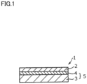
- Fig. 1 shows a cross section of a cell structure 1 including an electrolyte layer-anode composite member 5 and a cathode 2 in accordance with the present embodiment.
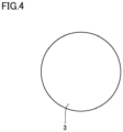
- the shape of cell structure 1 from an upper surface thereof may be, although not particularly limited to, a circular shape, to match the shape of the anode (for example, the circular shape shown in Fig. 4 ).
- Fig. 1 shows cell structure 1 in the form of stacked layers
- cell structure 1 is not limited thereto in shape.
- it may be rolled with an anode 3 inside to have a cylindrical shape so as to be hollow.
- the cylindrical shape has a hollow central portion and has anode 3, a solid electrolyte layer 4, and cathode 2 successively, concentrically arranged as viewed from the inside (not shown).
- the thickness Ta of anode 3 is larger than a thickness Tc of cathode 2, but cell structure 1 is not limited thereto in configuration.
- the cathode has a porous structure that can adsorb, dissociate and ionize oxygen molecules.
- a material for the cathode is a third metal oxide having a perovskite crystal structure, for example.
- a compound represented by the following formula (3): A3 1-p B3 p C3 q O 3- ⁇ formula (3) is preferably indicated as an example, where 0 ⁇ p ⁇ 1, 0 ⁇ q ⁇ 1, and ⁇ represents an oxygen vacancy concentration.
- An element A3 is at least one selected from the group consisting of La, Sm, and Ba.
- An element B3 is at least one selected from the group consisting of Sr and Ca.
- An element C3 is at least one selected from the group consisting of Fe, Co, Mn, and Ni.
- the third metal oxide includes lanthanum strontium cobalt ferrite (LSCF, La 1-c Sr c Co 1-d Fe d O 3- ⁇ , 0 ⁇ c ⁇ 1, 0 ⁇ d ⁇ 1, and ⁇ represents an oxygen vacancy concentration), lanthanum strontium manganite (LSM, La 1-e Sr e MnO 3- ⁇ , 0 ⁇ e ⁇ 1, and ⁇ represents an oxygen vacancy concentration), lanthanum strontium cobaltite (LSC, La 1-f Sr f CoO 3- ⁇ , 0 ⁇ f ⁇ 1, and ⁇ represents an oxygen vacancy concentration), samarium strontium cobaltite (SSC, Sm 1-g Sr g CoO 3- ⁇ , 0 ⁇ g ⁇ 1, and ⁇ represents an oxygen vacancy concentration), and the like.
- LSCF lanthanum strontium cobalt ferrite
- LSM La 1-e Sr e MnO 3- ⁇ , 0 ⁇ e ⁇ 1, and ⁇ represents an oxygen vacancy concentration
- the cathode may include a component other than the third metal oxide, but the content thereof is preferably small. For example, it is preferable that 99% by mass or more of the cathode is the third metal oxide. That is, the content ratio of the third metal oxide in the cathode is preferably 99% by mass or more and 100% by mass or less.
- the component other than the third metal oxide is not particularly limited, and can include a compound known as a material for the cathode (including a compound having no ion conductivity).
- the content ratio of the third metal oxide in the cathode can be determined by an X-ray diffraction method, for example.
- the cathode may include a catalyst such as nickel, iron, cobalt, or the like.
- the cathode including the catalyst is formed by mixing and sintering the catalyst and the third metal oxide.
- the thickness of the cathode is not particularly limited.
- the thickness of the cathode may be 10 ⁇ m or more and 30 ⁇ m or less, 15 ⁇ m or more and 30 ⁇ m or less, or 20 ⁇ m or more and 30 ⁇ m or less, for example.
- the thickness of the cathode can be calculated by taking an SEM photograph of a cross section of the cell structure, as described above.
- the composite member is fabricated by a first step of preparing a material for a solid electrolyte layer and a material for an anode, and a second step of forming a first layer (a precursor of the anode) including the material for the anode and a second layer (a precursor of the solid electrolyte layer) including the material for the solid electrolyte layer on a surface of the first layer, and firing the first and second layers.
- a cell structure is fabricated by additionally performing a third step of preparing a material for a cathode, and stacking and firing a layer including the material for the cathode on a surface of the solid electrolyte layer formed in the second step.
- a material for the solid electrolyte layer and a material for the anode are prepared.
- the material for the solid electrolyte layer and the material for the anode preferably include a binder from the viewpoint of shapability.
- the binder include known materials used in manufacturing ceramic materials, e.g., polymer binders such as cellulose derivatives (cellulose ethers) such as ethyl cellulose, vinyl acetate resins (including saponified vinyl acetate resins such as polyvinyl alcohol), and acrylic resins; and waxes such as paraffin wax.
- the amount of the binder included in the material for the anode is, for example, 1 to 15 parts by mass (3 to 10 parts by mass in particular) relative to 100 parts by mass of the above composite oxide (a mixture of the first metal oxide and at least one of nickel and a nickel compound).
- the amount of the binder is, for example, 1 to 20 parts by mass (1.5 to 15 parts by mass in particular).
- the amount of the binder included in the material for the solid electrolyte layer is, for example, 1 to 20 parts by mass (1.5 to 15 parts by mass in particular) relative to 100 parts by mass of the second metal oxide.
- Each material may include a dispersion medium such as water, an organic solvent (e.g., hydrocarbons such as toluene (aromatic hydrocarbons); alcohols such as ethanol and isopropanol; and carbitols such as butyl carbitol acetate), as necessary.
- an organic solvent e.g., hydrocarbons such as toluene (aromatic hydrocarbons); alcohols such as ethanol and isopropanol; and carbitols such as butyl carbitol acetate
- additives such as a surfactant, a deflocculant (such as polycarboxylic acid), and the like, as necessary.
- a first layer including the material for the anode and a second layer including the material for the solid electrolyte layer are stacked to form a stacked body, and the stack body is fired.
- each layer is not particularly limited, and may be selected as appropriate depending on the layer's desired thickness.
- the first layer is typically shaped by performing press forming, tape casting, or the like on the material for the anode.
- the second layer is typically shaped by performing an existing method such as screen printing, spray coating, spin coating, dip coating, or the like on the material for the solid electrolyte layer.
- the material for the anode is formed into a predetermined shape by press forming.
- the predetermined shape is, for example, in the form of a pellet, a plate, a sheet, or the like.
- the material for the anode may be granulated and then granules may be shaped. If necessary, the obtained granules may be disintegrated and then shaped.
- the material for the solid electrolyte layer is applied to a surface of the shaped first layer for example by screen printing, spray coating, spin coating, dip coating, or the like to form a second layer.
- a stacked body is thus obtained.
- a step of calcining the first layer may be performed.
- the calcination may be performed at a temperature lower than a temperature at which the material for the anode is sintered (e.g., 900°C to 1 100°C). The calcination facilitates applying the material for the solid electrolyte layer.
- the obtained stacked body is fired.
- the firing is performed by heating the obtained stacked body in an oxygen-containing atmosphere to 1200°C to 1700°C, for example.
- the oxygen content in the firing atmosphere is not particularly limited.
- the firing may be performed for example in an air atmosphere (oxygen content: about 20% by volume) or in pure oxygen (oxygen content: 100% by volume).
- the firing can be performed at a normal pressure or a high pressure.
- a resin component such as a binder included in each material may be removed. That is, after the material for the solid electrolyte layer is applied, the stacked body is heated in the air to a relatively low temperature of about 500°C to 700°C to remove a resin component included in each material. Thereafter, the above-described firing is performed.
- the first and second layers are co-sintered.
- the anode and the solid electrolyte layer are thus formed to be integrated.
- a material for the cathode is prepared, and a layer including the material for the cathode is stacked and fired on a surface of the solid electrolyte layer formed in the second step.
- the cathode is thus formed.
- the firing is performed in an oxygen-containing atmosphere similar to the above at 800 to 1100°C, for example.
- the material for the cathode may also be stacked on the surface of the solid electrolyte layer by using a cathode dispersion such as paste or slurry mixed with a binder or the like.
- the cathode dispersion is stacked for example by the same method as the method for forming the second layer.
- the amount of the binder included in the cathode dispersion is, for example, 1 to 20 parts by mass (1.5 to 15 parts by mass, in particular) relative to 100 parts by mass of the first metal oxide.
- a composite member obtained by co-sintering a first layer (a precursor of an anode) made of a material for the anode including 30% by volume of BZY (BaZr 0.8 Y 0.2 O 2.9 ) and 70% by volume of NiO, and a second layer (a precursor of a solid electrolyte layer) including BZY (BaZr 0.8 Y 0.2 O 2.9 ) was used as a model.
- Residual stress and a warpage amount were simulated in the above model, with the thickness of the co-sintered first layer (that is, the thickness Ta of the anode) being changed from 600 ⁇ m to 1800 ⁇ m in 300- ⁇ m increments.
- the thickness Te of the solid electrolyte layer was set to 20 ⁇ m.
- the warpage amount was obtained as a minimal distance between a horizontal plane and the highest point of a convex of the composite member, based on an assumption that the composite member was placed on the horizontal plane with its convex facing upward. It was assumed that the residual stress was measured by a measuring method using an X-ray diffraction method. Figs. 2 and 3 show results.
- a cell structure including a composite member having the same configuration as that described above and a 10- ⁇ m-thick cathode including LSCF (La 0.6 Sr 0.4 Co 0.2 Feo. 8 O 3- ⁇ ) was additionally fabricated, and a transverse intensity thereof was measured according to JIS R 1601:2008.
- the transverse intensity (actually measured value) of the cell structure was 152 MPa.
- both the transverse intensity of the cell structure and the residual stress of the composite member are influenced by the material and the thickness of each of the anode and the solid electrolyte layer.
- the transverse intensity of the cell structure and the residual stress of the composite member increase or decrease depending on the material and the thickness of each of the anode and the solid electrolyte layer, they have the same tendency to increase or decrease. Accordingly, for example when the anode includes the first metal oxide represented by the above formula (1) and the solid electrolyte layer includes the second metal oxide represented by the above formula (2), the residual stress of the composite member also decreases if the thickness Ta of the anode is 850 ⁇ m or more.
- the warpage amount decreases if the thickness Ta of the anode is 850 ⁇ m or more.
Landscapes
- Chemical & Material Sciences (AREA)
- Engineering & Computer Science (AREA)
- Chemical Kinetics & Catalysis (AREA)
- General Chemical & Material Sciences (AREA)
- Electrochemistry (AREA)
- Manufacturing & Machinery (AREA)
- Sustainable Energy (AREA)
- Sustainable Development (AREA)
- Life Sciences & Earth Sciences (AREA)
- Materials Engineering (AREA)
- Organic Chemistry (AREA)
- Composite Materials (AREA)
- Inorganic Chemistry (AREA)
- Ceramic Engineering (AREA)
- Inert Electrodes (AREA)
- Fuel Cell (AREA)
Claims (7)
- Elektrolytschicht-Anode-Verbundglied, umfassend:eine Anode, die ein erstes Metalloxid mit einer Perowskit-Kristallstruktur aufweist, undeine solide Elektrolytschicht, die ein zweites Metalloxid mit einer Perowskit-Kristallstruktur aufweist,wobei die Anode Nickel und/oder eine Nickelverbindung enthält,wobei die Anode eine schichtartige Form aufweist,wobei die solide Elektrolytschicht eine schichtartige Form aufweist,wobei die solide Elektrolytschicht auf die Anode gestapelt ist,wobei die Anode eine Dicke Ta von 900 µm oder mehr und 1200 µm oder weniger aufweist,wobei die Dicke Ta (µm) der Anode und der Durchmesser Da (cm) der Anode die Beziehung 70≤Ta/Da≤150 erfüllen.
- Elektrolytschicht-Anode-Verbundglied nach Anspruch 1, wobei das erste Metalloxid durch die folgende Formel (1) wiedergegeben wird:
A1mB1nC11-nO3-δ Formel (1)
wobei ein Element A1 wenigstens eines ist, das aus der Gruppe ausgewählt ist, die aus Ba, Ca und Sr besteht, wobei ein Element B1 wenigstens eines ist, das aus der Gruppe ausgewählt ist, die aus Ce und Zr besteht, wobei ein Element C1 wenigstens eines ist, das aus der Gruppe ausgewählt ist, die aus Y, Yb, Er, Ho, Tm, Gd, In und Sc besteht, wobei 0,85≤m≤1, 0,5≤n<1 und wobei δ eine Sauerstoffdefektkonzentration wiedergibt. - Elektrolytschicht-Anode-Verbundglied nach Anspruch 1 oder 2, wobei das zweite Metalloxid durch die folgende Formel (2) wiedergegeben wird:
A2xB2yC21-yO3-δ Formel (2)
wobei ein Element A2 wenigstens eines ist, das aus der Gruppe ausgewählt ist, die aus Ba, Ca und Sr besteht, wobei ein Element B2 wenigstens eines ist, das aus der Gruppe ausgewählt ist, die aus Ce und Zr besteht, wobei ein Element C2 wenigstens eines ist, das aus der Gruppe ausgewählt ist, die aus Y, Yb, Er, Ho, Tm, Gd, In und Sc besteht, wobei 0,85≤x≤1, 0,5≤y<1 und wobei δ eine Sauerstoffdefekt wiedergibt. - Elektrolytschicht-Anode-Verbundglied nach einem der Ansprüche 1 bis 3, wobei die Dicke Ta der Anode und die Dicke Te der soliden Elektrolytschicht die Beziehung 0,003≤Te/Ta≤0,036 erfüllen.
- Elektrolytschicht-Anode-Verbundglied nach einem der Ansprüche 1 bis 4, wobei die Dicke Te der soliden Elektrolytschicht 5 µm oder mehr und 30 µm oder weniger beträgt.
- Elektrolytschicht-Anode-Verbundglied nach einem der Ansprüche, wobei der Durchmesser Da der Anode 5 cm oder mehr und 15 cm oder weniger beträgt.
- Zellenstruktur, umfassend:das Elektrolytschicht-Anode-Verbundglied gemäß einem der Ansprüche 1 bis 6, undeine Kathode,wobei die Kathode eine schichtartige Form aufweist,wobei die Kathode auf der soliden Elektrolytschicht des Elektrolytschicht-Anode-Verbundglieds gestapelt ist.
Applications Claiming Priority (2)
| Application Number | Priority Date | Filing Date | Title |
|---|---|---|---|
| JP2018039522 | 2018-03-06 | ||
| PCT/JP2019/005247 WO2019171900A1 (ja) | 2018-03-06 | 2019-02-14 | 電解質層-アノード複合部材およびセル構造体 |
Publications (4)
| Publication Number | Publication Date |
|---|---|
| EP3764448A1 EP3764448A1 (de) | 2021-01-13 |
| EP3764448A4 EP3764448A4 (de) | 2021-12-01 |
| EP3764448B1 true EP3764448B1 (de) | 2024-11-13 |
| EP3764448B9 EP3764448B9 (de) | 2025-03-26 |
Family
ID=67846067
Family Applications (1)
| Application Number | Title | Priority Date | Filing Date |
|---|---|---|---|
| EP19764639.1A Active EP3764448B9 (de) | 2018-03-06 | 2019-02-14 | Elektrolytschichtanoden-verbundelement und zellstruktur |
Country Status (5)
| Country | Link |
|---|---|
| US (1) | US20210013534A1 (de) |
| EP (1) | EP3764448B9 (de) |
| JP (1) | JP7156360B2 (de) |
| CN (1) | CN111801827B (de) |
| WO (1) | WO2019171900A1 (de) |
Families Citing this family (1)
| Publication number | Priority date | Publication date | Assignee | Title |
|---|---|---|---|---|
| CN119920997A (zh) * | 2025-01-24 | 2025-05-02 | 南方科技大学 | 全固态电池及用电设备 |
Family Cites Families (14)
| Publication number | Priority date | Publication date | Assignee | Title |
|---|---|---|---|---|
| EP0419163B1 (de) * | 1989-09-18 | 1995-01-11 | Ngk Insulators, Ltd. | Brennstoffzellengenerator |
| US8153318B2 (en) * | 2006-11-08 | 2012-04-10 | Alan Devoe | Method of making a fuel cell device |
| JP5051741B2 (ja) * | 2006-01-23 | 2012-10-17 | 日本電信電話株式会社 | 平板型固体酸化物形燃料電池の作製方法 |
| JP2010238432A (ja) * | 2009-03-30 | 2010-10-21 | Mitsubishi Materials Corp | 燃料電池の発電セル |
| JP5439160B2 (ja) * | 2009-12-24 | 2014-03-12 | 日本碍子株式会社 | 固体酸化物形燃料電池セルの製造方法、及び、同セルの分割体の成形体の製造方法 |
| JP5451653B2 (ja) * | 2011-01-06 | 2014-03-26 | 日本電信電話株式会社 | ガスシール材 |
| JP5936897B2 (ja) | 2012-03-28 | 2016-06-22 | 住友電気工業株式会社 | 固体電解質、固体電解質の製造方法、固体電解質積層体及び固体電解質積層体の製造方法及び燃料電池 |
| KR101439176B1 (ko) * | 2013-04-26 | 2014-09-17 | 한국과학기술연구원 | 이중 전해질층을 포함하는 프로톤 전도성 고체 산화물 연료전지 및 유사 대칭성 적층 구조의 동시소성을 이용한 그 제조방법 |
| JP6132259B2 (ja) * | 2013-07-18 | 2017-05-24 | 住友電気工業株式会社 | 燃料電池用複合材料、燃料電池用複合材料の製造方法及び燃料電池 |
| JP6398647B2 (ja) * | 2014-11-21 | 2018-10-03 | 住友電気工業株式会社 | 固体酸化物型燃料電池用アノードの製造方法および燃料電池用電解質層−電極接合体の製造方法 |
| JP6601488B2 (ja) * | 2015-03-30 | 2019-11-06 | 住友電気工業株式会社 | プロトン伝導体、燃料電池用固体電解質層、セル構造体およびそれを備える燃料電池 |
| WO2017014069A1 (ja) * | 2015-07-17 | 2017-01-26 | 住友電気工業株式会社 | 燃料電池用電解質層-アノード複合部材およびその製造方法 |
| JP6783042B2 (ja) * | 2015-08-17 | 2020-11-11 | 住友電気工業株式会社 | セル構造体の製造方法 |
| JP7110544B2 (ja) | 2016-09-06 | 2022-08-02 | 東洋製罐株式会社 | 合成樹脂製ボトル |
-
2019
- 2019-02-14 US US16/977,235 patent/US20210013534A1/en not_active Abandoned
- 2019-02-14 CN CN201980016578.7A patent/CN111801827B/zh active Active
- 2019-02-14 EP EP19764639.1A patent/EP3764448B9/de active Active
- 2019-02-14 JP JP2020504883A patent/JP7156360B2/ja active Active
- 2019-02-14 WO PCT/JP2019/005247 patent/WO2019171900A1/ja not_active Ceased
Also Published As
| Publication number | Publication date |
|---|---|
| CN111801827A (zh) | 2020-10-20 |
| EP3764448A4 (de) | 2021-12-01 |
| CN111801827B (zh) | 2023-08-18 |
| JPWO2019171900A1 (ja) | 2021-02-12 |
| US20210013534A1 (en) | 2021-01-14 |
| EP3764448A1 (de) | 2021-01-13 |
| WO2019171900A1 (ja) | 2019-09-12 |
| JP7156360B2 (ja) | 2022-10-19 |
| EP3764448B9 (de) | 2025-03-26 |
Similar Documents
| Publication | Publication Date | Title |
|---|---|---|
| KR100886239B1 (ko) | 반응 부산물 발생 억제 방법 및 이를 이용한 고체산화물연료전지와 그 제조방법 | |
| CN107078328B (zh) | 用于制造固体氧化物燃料电池的方法 | |
| US20180037508A1 (en) | Proton conductor, solid electrolyte layer for fuel cell, cell structure, and fuel cell including the same | |
| KR101835956B1 (ko) | 전극의 제조방법, 이로 제조된 전극, 상기 전극을 포함하는 전극 구조체, 상기 전극을 포함하는 연료 전지 또는 금속 공기 이차 전지, 상기 연료 전지 또는 금속 공기 이차 전지를 포함하는 전지 모듈, 및 전극 제조용 조성물 | |
| JP6573243B2 (ja) | 空気極組成物、空気極およびこれを含む燃料電池 | |
| KR101124859B1 (ko) | 고체산화물 연료전지용 lscf 파우더 제조방법 및 단위전지의 제조방법 | |
| KR101218980B1 (ko) | 연료 전지용 전극 재료, 이를 포함하는 연료 전지 및 이의 제조방법 | |
| KR101842319B1 (ko) | 고체 산화물 연료 전지 및 이의 제조방법 | |
| EP3764448B1 (de) | Elektrolytschichtanoden-verbundelement und zellstruktur | |
| JP2003208902A (ja) | 固体電解質型燃料電池 | |
| KR102111859B1 (ko) | 고체산화물 연료 전지 및 이를 포함하는 전지 모듈 | |
| CN107646151A (zh) | 氧化物颗粒、包含其的阴极和包含其的燃料电池 | |
| EP3764447B1 (de) | Zellstruktur | |
| US20120189944A1 (en) | Solid electrolyte for solid oxide fuel cell, and solid oxide fuel cell including the solid electrolyte | |
| JP6526204B2 (ja) | 固体酸化物燃料電池の製造方法、固体酸化物燃料電池およびこれを含む電池モジュール | |
| JP2018139180A (ja) | 固体電解質部材の製造方法 | |
| KR20170010625A (ko) | 고체산화물 연료전지용 그린시트 적층체 및 고체산화물 연료전지의 제조방법 | |
| KR102103053B1 (ko) | 평판형 고체 산화물 연료전지 | |
| EP3309888B1 (de) | Precursor für festoxidbrennstoffzelle und verfahren zur herstellung einer verbundfolie für eine festoxidbrennstoffzelle | |
| KR101940712B1 (ko) | 고체 산화물 연료 전지 및 이의 제조방법 | |
| KR101257431B1 (ko) | 막-전극 어셈블리, 이의 제조 방법 및 상기 막-전극 어셈블리를 포함하는 스택 및 고체 산화물 연료전지 | |
| CN111819720B (zh) | 燃料电池用电解质层-阳极复合部件、电池结构体、燃料电池以及复合部件的制造方法 | |
| US20120214085A1 (en) | Fuel cell of solid oxide fuel cell | |
| KR20180110463A (ko) | 애노드, 전극 구조체, 이를 포함하는 연료 전지 및 이의 제조방법 | |
| KR20160068205A (ko) | 고체 산화물 연료 전지 및 이의 제조방법 |
Legal Events
| Date | Code | Title | Description |
|---|---|---|---|
| STAA | Information on the status of an ep patent application or granted ep patent |
Free format text: STATUS: THE INTERNATIONAL PUBLICATION HAS BEEN MADE |
|
| PUAI | Public reference made under article 153(3) epc to a published international application that has entered the european phase |
Free format text: ORIGINAL CODE: 0009012 |
|
| STAA | Information on the status of an ep patent application or granted ep patent |
Free format text: STATUS: REQUEST FOR EXAMINATION WAS MADE |
|
| 17P | Request for examination filed |
Effective date: 20200827 |
|
| AK | Designated contracting states |
Kind code of ref document: A1 Designated state(s): AL AT BE BG CH CY CZ DE DK EE ES FI FR GB GR HR HU IE IS IT LI LT LU LV MC MK MT NL NO PL PT RO RS SE SI SK SM TR |
|
| AX | Request for extension of the european patent |
Extension state: BA ME |
|
| DAV | Request for validation of the european patent (deleted) | ||
| DAX | Request for extension of the european patent (deleted) | ||
| A4 | Supplementary search report drawn up and despatched |
Effective date: 20211104 |
|
| RIC1 | Information provided on ipc code assigned before grant |
Ipc: H01M 8/1231 20160101ALI20211028BHEP Ipc: H01M 8/124 20160101ALI20211028BHEP Ipc: H01M 8/00 20160101ALI20211028BHEP Ipc: H01M 4/90 20060101ALI20211028BHEP Ipc: H01M 8/12 20160101ALI20211028BHEP Ipc: C01G 25/00 20060101ALI20211028BHEP Ipc: H01M 8/126 20160101ALI20211028BHEP Ipc: H01M 8/1253 20160101ALI20211028BHEP Ipc: H01M 8/1246 20160101ALI20211028BHEP Ipc: H01M 4/86 20060101ALI20211028BHEP Ipc: H01M 8/1213 20160101AFI20211028BHEP |
|
| GRAP | Despatch of communication of intention to grant a patent |
Free format text: ORIGINAL CODE: EPIDOSNIGR1 |
|
| STAA | Information on the status of an ep patent application or granted ep patent |
Free format text: STATUS: GRANT OF PATENT IS INTENDED |
|
| RIC1 | Information provided on ipc code assigned before grant |
Ipc: H01M 8/1231 20160101ALI20240531BHEP Ipc: H01M 8/124 20160101ALI20240531BHEP Ipc: H01M 8/00 20160101ALI20240531BHEP Ipc: H01M 4/90 20060101ALI20240531BHEP Ipc: H01M 8/12 20160101ALI20240531BHEP Ipc: C01G 25/00 20060101ALI20240531BHEP Ipc: H01M 8/126 20160101ALI20240531BHEP Ipc: H01M 8/1253 20160101ALI20240531BHEP Ipc: H01M 8/1246 20160101ALI20240531BHEP Ipc: H01M 4/86 20060101ALI20240531BHEP Ipc: H01M 8/1213 20160101AFI20240531BHEP |
|
| INTG | Intention to grant announced |
Effective date: 20240625 |
|
| GRAS | Grant fee paid |
Free format text: ORIGINAL CODE: EPIDOSNIGR3 |
|
| GRAA | (expected) grant |
Free format text: ORIGINAL CODE: 0009210 |
|
| STAA | Information on the status of an ep patent application or granted ep patent |
Free format text: STATUS: THE PATENT HAS BEEN GRANTED |
|
| P01 | Opt-out of the competence of the unified patent court (upc) registered |
Free format text: CASE NUMBER: APP_50715/2024 Effective date: 20240906 |
|
| AK | Designated contracting states |
Kind code of ref document: B1 Designated state(s): AL AT BE BG CH CY CZ DE DK EE ES FI FR GB GR HR HU IE IS IT LI LT LU LV MC MK MT NL NO PL PT RO RS SE SI SK SM TR |
|
| REG | Reference to a national code |
Ref country code: GB Ref legal event code: FG4D |
|
| REG | Reference to a national code |
Ref country code: CH Ref legal event code: EP |
|
| REG | Reference to a national code |
Ref country code: DE Ref legal event code: R096 Ref document number: 602019061962 Country of ref document: DE |
|
| REG | Reference to a national code |
Ref country code: IE Ref legal event code: FG4D |
|
| REG | Reference to a national code |
Ref country code: CH Ref legal event code: PK Free format text: BERICHTIGUNG B9 |
|
| REG | Reference to a national code |
Ref country code: LT Ref legal event code: MG9D |
|
| REG | Reference to a national code |
Ref country code: NL Ref legal event code: MP Effective date: 20241113 |
|
| PG25 | Lapsed in a contracting state [announced via postgrant information from national office to epo] |
Ref country code: HR Free format text: LAPSE BECAUSE OF FAILURE TO SUBMIT A TRANSLATION OF THE DESCRIPTION OR TO PAY THE FEE WITHIN THE PRESCRIBED TIME-LIMIT Effective date: 20241113 Ref country code: IS Free format text: LAPSE BECAUSE OF FAILURE TO SUBMIT A TRANSLATION OF THE DESCRIPTION OR TO PAY THE FEE WITHIN THE PRESCRIBED TIME-LIMIT Effective date: 20250313 Ref country code: PT Free format text: LAPSE BECAUSE OF FAILURE TO SUBMIT A TRANSLATION OF THE DESCRIPTION OR TO PAY THE FEE WITHIN THE PRESCRIBED TIME-LIMIT Effective date: 20250313 |
|
| PG25 | Lapsed in a contracting state [announced via postgrant information from national office to epo] |
Ref country code: NL Free format text: LAPSE BECAUSE OF FAILURE TO SUBMIT A TRANSLATION OF THE DESCRIPTION OR TO PAY THE FEE WITHIN THE PRESCRIBED TIME-LIMIT Effective date: 20241113 Ref country code: FI Free format text: LAPSE BECAUSE OF FAILURE TO SUBMIT A TRANSLATION OF THE DESCRIPTION OR TO PAY THE FEE WITHIN THE PRESCRIBED TIME-LIMIT Effective date: 20241113 |
|
| REG | Reference to a national code |
Ref country code: AT Ref legal event code: MK05 Ref document number: 1742391 Country of ref document: AT Kind code of ref document: T Effective date: 20241113 |
|
| PG25 | Lapsed in a contracting state [announced via postgrant information from national office to epo] |
Ref country code: BG Free format text: LAPSE BECAUSE OF FAILURE TO SUBMIT A TRANSLATION OF THE DESCRIPTION OR TO PAY THE FEE WITHIN THE PRESCRIBED TIME-LIMIT Effective date: 20241113 |
|
| PG25 | Lapsed in a contracting state [announced via postgrant information from national office to epo] |
Ref country code: ES Free format text: LAPSE BECAUSE OF FAILURE TO SUBMIT A TRANSLATION OF THE DESCRIPTION OR TO PAY THE FEE WITHIN THE PRESCRIBED TIME-LIMIT Effective date: 20241113 |
|
| PG25 | Lapsed in a contracting state [announced via postgrant information from national office to epo] |
Ref country code: NO Free format text: LAPSE BECAUSE OF FAILURE TO SUBMIT A TRANSLATION OF THE DESCRIPTION OR TO PAY THE FEE WITHIN THE PRESCRIBED TIME-LIMIT Effective date: 20250213 |
|
| PG25 | Lapsed in a contracting state [announced via postgrant information from national office to epo] |
Ref country code: AT Free format text: LAPSE BECAUSE OF FAILURE TO SUBMIT A TRANSLATION OF THE DESCRIPTION OR TO PAY THE FEE WITHIN THE PRESCRIBED TIME-LIMIT Effective date: 20241113 Ref country code: LV Free format text: LAPSE BECAUSE OF FAILURE TO SUBMIT A TRANSLATION OF THE DESCRIPTION OR TO PAY THE FEE WITHIN THE PRESCRIBED TIME-LIMIT Effective date: 20241113 Ref country code: GR Free format text: LAPSE BECAUSE OF FAILURE TO SUBMIT A TRANSLATION OF THE DESCRIPTION OR TO PAY THE FEE WITHIN THE PRESCRIBED TIME-LIMIT Effective date: 20250214 |
|
| PG25 | Lapsed in a contracting state [announced via postgrant information from national office to epo] |
Ref country code: PL Free format text: LAPSE BECAUSE OF FAILURE TO SUBMIT A TRANSLATION OF THE DESCRIPTION OR TO PAY THE FEE WITHIN THE PRESCRIBED TIME-LIMIT Effective date: 20241113 |
|
| PG25 | Lapsed in a contracting state [announced via postgrant information from national office to epo] |
Ref country code: RS Free format text: LAPSE BECAUSE OF FAILURE TO SUBMIT A TRANSLATION OF THE DESCRIPTION OR TO PAY THE FEE WITHIN THE PRESCRIBED TIME-LIMIT Effective date: 20250213 |
|
| PG25 | Lapsed in a contracting state [announced via postgrant information from national office to epo] |
Ref country code: SM Free format text: LAPSE BECAUSE OF FAILURE TO SUBMIT A TRANSLATION OF THE DESCRIPTION OR TO PAY THE FEE WITHIN THE PRESCRIBED TIME-LIMIT Effective date: 20241113 |
|
| PG25 | Lapsed in a contracting state [announced via postgrant information from national office to epo] |
Ref country code: DK Free format text: LAPSE BECAUSE OF FAILURE TO SUBMIT A TRANSLATION OF THE DESCRIPTION OR TO PAY THE FEE WITHIN THE PRESCRIBED TIME-LIMIT Effective date: 20241113 |
|
| PG25 | Lapsed in a contracting state [announced via postgrant information from national office to epo] |
Ref country code: RO Free format text: LAPSE BECAUSE OF FAILURE TO SUBMIT A TRANSLATION OF THE DESCRIPTION OR TO PAY THE FEE WITHIN THE PRESCRIBED TIME-LIMIT Effective date: 20241113 |
|
| PG25 | Lapsed in a contracting state [announced via postgrant information from national office to epo] |
Ref country code: SK Free format text: LAPSE BECAUSE OF FAILURE TO SUBMIT A TRANSLATION OF THE DESCRIPTION OR TO PAY THE FEE WITHIN THE PRESCRIBED TIME-LIMIT Effective date: 20241113 |
|
| PG25 | Lapsed in a contracting state [announced via postgrant information from national office to epo] |
Ref country code: CZ Free format text: LAPSE BECAUSE OF FAILURE TO SUBMIT A TRANSLATION OF THE DESCRIPTION OR TO PAY THE FEE WITHIN THE PRESCRIBED TIME-LIMIT Effective date: 20241113 |
|
| PG25 | Lapsed in a contracting state [announced via postgrant information from national office to epo] |
Ref country code: IT Free format text: LAPSE BECAUSE OF FAILURE TO SUBMIT A TRANSLATION OF THE DESCRIPTION OR TO PAY THE FEE WITHIN THE PRESCRIBED TIME-LIMIT Effective date: 20241113 |
|
| REG | Reference to a national code |
Ref country code: DE Ref legal event code: R097 Ref document number: 602019061962 Country of ref document: DE |
|
| PG25 | Lapsed in a contracting state [announced via postgrant information from national office to epo] |
Ref country code: SE Free format text: LAPSE BECAUSE OF FAILURE TO SUBMIT A TRANSLATION OF THE DESCRIPTION OR TO PAY THE FEE WITHIN THE PRESCRIBED TIME-LIMIT Effective date: 20241113 |
|
| PG25 | Lapsed in a contracting state [announced via postgrant information from national office to epo] |
Ref country code: MC Free format text: LAPSE BECAUSE OF FAILURE TO SUBMIT A TRANSLATION OF THE DESCRIPTION OR TO PAY THE FEE WITHIN THE PRESCRIBED TIME-LIMIT Effective date: 20241113 |
|
| PLBE | No opposition filed within time limit |
Free format text: ORIGINAL CODE: 0009261 |
|
| STAA | Information on the status of an ep patent application or granted ep patent |
Free format text: STATUS: NO OPPOSITION FILED WITHIN TIME LIMIT |
|
| REG | Reference to a national code |
Ref country code: CH Ref legal event code: PL |
|
| PG25 | Lapsed in a contracting state [announced via postgrant information from national office to epo] |
Ref country code: LU Free format text: LAPSE BECAUSE OF NON-PAYMENT OF DUE FEES Effective date: 20250214 |
|
| PG25 | Lapsed in a contracting state [announced via postgrant information from national office to epo] |
Ref country code: CH Free format text: LAPSE BECAUSE OF NON-PAYMENT OF DUE FEES Effective date: 20250228 |
|
| 26N | No opposition filed |
Effective date: 20250814 |
|
| GBPC | Gb: european patent ceased through non-payment of renewal fee |
Effective date: 20250214 |
|
| REG | Reference to a national code |
Ref country code: BE Ref legal event code: MM Effective date: 20250228 |
|
| PG25 | Lapsed in a contracting state [announced via postgrant information from national office to epo] |
Ref country code: GB Free format text: LAPSE BECAUSE OF NON-PAYMENT OF DUE FEES Effective date: 20250214 |
|
| PG25 | Lapsed in a contracting state [announced via postgrant information from national office to epo] |
Ref country code: FR Free format text: LAPSE BECAUSE OF NON-PAYMENT OF DUE FEES Effective date: 20250228 |
|
| PG25 | Lapsed in a contracting state [announced via postgrant information from national office to epo] |
Ref country code: BE Free format text: LAPSE BECAUSE OF NON-PAYMENT OF DUE FEES Effective date: 20250228 |
|
| PG25 | Lapsed in a contracting state [announced via postgrant information from national office to epo] |
Ref country code: IE Free format text: LAPSE BECAUSE OF NON-PAYMENT OF DUE FEES Effective date: 20250214 |
|
| PGFP | Annual fee paid to national office [announced via postgrant information from national office to epo] |
Ref country code: DE Payment date: 20251230 Year of fee payment: 8 |