EP3764447B1 - Zellstruktur - Google Patents
Zellstruktur Download PDFInfo
- Publication number
- EP3764447B1 EP3764447B1 EP19763876.0A EP19763876A EP3764447B1 EP 3764447 B1 EP3764447 B1 EP 3764447B1 EP 19763876 A EP19763876 A EP 19763876A EP 3764447 B1 EP3764447 B1 EP 3764447B1
- Authority
- EP
- European Patent Office
- Prior art keywords
- cathode
- solid electrolyte
- electrolyte layer
- anode
- resistance
- Prior art date
- Legal status (The legal status is an assumption and is not a legal conclusion. Google has not performed a legal analysis and makes no representation as to the accuracy of the status listed.)
- Active
Links
Images
Classifications
-
- C—CHEMISTRY; METALLURGY
- C01—INORGANIC CHEMISTRY
- C01G—COMPOUNDS CONTAINING METALS NOT COVERED BY SUBCLASSES C01D OR C01F
- C01G51/00—Compounds of cobalt
- C01G51/40—Complex oxides containing cobalt and at least one other metal element
- C01G51/70—Complex oxides containing cobalt and at least one other metal element containing rare earths, e.g. LaCoO3
-
- H—ELECTRICITY
- H01—ELECTRIC ELEMENTS
- H01M—PROCESSES OR MEANS, e.g. BATTERIES, FOR THE DIRECT CONVERSION OF CHEMICAL ENERGY INTO ELECTRICAL ENERGY
- H01M4/00—Electrodes
- H01M4/86—Inert electrodes with catalytic activity, e.g. for fuel cells
- H01M4/8605—Porous electrodes
- H01M4/8621—Porous electrodes containing only metallic or ceramic material, e.g. made by sintering or sputtering
-
- H—ELECTRICITY
- H01—ELECTRIC ELEMENTS
- H01M—PROCESSES OR MEANS, e.g. BATTERIES, FOR THE DIRECT CONVERSION OF CHEMICAL ENERGY INTO ELECTRICAL ENERGY
- H01M4/00—Electrodes
- H01M4/86—Inert electrodes with catalytic activity, e.g. for fuel cells
- H01M4/8663—Selection of inactive substances as ingredients for catalytic active masses, e.g. binders, fillers
- H01M4/8673—Electrically conductive fillers
-
- H—ELECTRICITY
- H01—ELECTRIC ELEMENTS
- H01M—PROCESSES OR MEANS, e.g. BATTERIES, FOR THE DIRECT CONVERSION OF CHEMICAL ENERGY INTO ELECTRICAL ENERGY
- H01M4/00—Electrodes
- H01M4/86—Inert electrodes with catalytic activity, e.g. for fuel cells
- H01M4/88—Processes of manufacture
- H01M4/8825—Methods for deposition of the catalytic active composition
- H01M4/8828—Coating with slurry or ink
- H01M4/8835—Screen printing
-
- H—ELECTRICITY
- H01—ELECTRIC ELEMENTS
- H01M—PROCESSES OR MEANS, e.g. BATTERIES, FOR THE DIRECT CONVERSION OF CHEMICAL ENERGY INTO ELECTRICAL ENERGY
- H01M4/00—Electrodes
- H01M4/86—Inert electrodes with catalytic activity, e.g. for fuel cells
- H01M4/88—Processes of manufacture
- H01M4/8878—Treatment steps after deposition of the catalytic active composition or after shaping of the electrode being free-standing body
- H01M4/8882—Heat treatment, e.g. drying, baking
- H01M4/8885—Sintering or firing
- H01M4/8889—Cosintering or cofiring of a catalytic active layer with another type of layer
-
- H—ELECTRICITY
- H01—ELECTRIC ELEMENTS
- H01M—PROCESSES OR MEANS, e.g. BATTERIES, FOR THE DIRECT CONVERSION OF CHEMICAL ENERGY INTO ELECTRICAL ENERGY
- H01M4/00—Electrodes
- H01M4/86—Inert electrodes with catalytic activity, e.g. for fuel cells
- H01M4/90—Selection of catalytic material
- H01M4/9016—Oxides, hydroxides or oxygenated metallic salts
- H01M4/9025—Oxides specially used in fuel cell operating at high temperature, e.g. SOFC
- H01M4/9033—Complex oxides, optionally doped, of the type M1MeO3, M1 being an alkaline earth metal or a rare earth, Me being a metal, e.g. perovskites
-
- H—ELECTRICITY
- H01—ELECTRIC ELEMENTS
- H01M—PROCESSES OR MEANS, e.g. BATTERIES, FOR THE DIRECT CONVERSION OF CHEMICAL ENERGY INTO ELECTRICAL ENERGY
- H01M8/00—Fuel cells; Manufacture thereof
- H01M8/10—Fuel cells with solid electrolytes
- H01M8/12—Fuel cells with solid electrolytes operating at high temperature, e.g. with stabilised ZrO2 electrolyte
- H01M8/1213—Fuel cells with solid electrolytes operating at high temperature, e.g. with stabilised ZrO2 electrolyte characterised by the electrode/electrolyte combination or the supporting material
-
- H—ELECTRICITY
- H01—ELECTRIC ELEMENTS
- H01M—PROCESSES OR MEANS, e.g. BATTERIES, FOR THE DIRECT CONVERSION OF CHEMICAL ENERGY INTO ELECTRICAL ENERGY
- H01M8/00—Fuel cells; Manufacture thereof
- H01M8/10—Fuel cells with solid electrolytes
- H01M8/12—Fuel cells with solid electrolytes operating at high temperature, e.g. with stabilised ZrO2 electrolyte
- H01M8/1231—Fuel cells with solid electrolytes operating at high temperature, e.g. with stabilised ZrO2 electrolyte with both reactants being gaseous or vaporised
-
- H—ELECTRICITY
- H01—ELECTRIC ELEMENTS
- H01M—PROCESSES OR MEANS, e.g. BATTERIES, FOR THE DIRECT CONVERSION OF CHEMICAL ENERGY INTO ELECTRICAL ENERGY
- H01M8/00—Fuel cells; Manufacture thereof
- H01M8/10—Fuel cells with solid electrolytes
- H01M8/12—Fuel cells with solid electrolytes operating at high temperature, e.g. with stabilised ZrO2 electrolyte
- H01M8/124—Fuel cells with solid electrolytes operating at high temperature, e.g. with stabilised ZrO2 electrolyte characterised by the process of manufacturing or by the material of the electrolyte
- H01M8/1246—Fuel cells with solid electrolytes operating at high temperature, e.g. with stabilised ZrO2 electrolyte characterised by the process of manufacturing or by the material of the electrolyte the electrolyte consisting of oxides
- H01M8/1253—Fuel cells with solid electrolytes operating at high temperature, e.g. with stabilised ZrO2 electrolyte characterised by the process of manufacturing or by the material of the electrolyte the electrolyte consisting of oxides the electrolyte containing zirconium oxide
-
- H—ELECTRICITY
- H01—ELECTRIC ELEMENTS
- H01M—PROCESSES OR MEANS, e.g. BATTERIES, FOR THE DIRECT CONVERSION OF CHEMICAL ENERGY INTO ELECTRICAL ENERGY
- H01M8/00—Fuel cells; Manufacture thereof
- H01M8/10—Fuel cells with solid electrolytes
- H01M8/12—Fuel cells with solid electrolytes operating at high temperature, e.g. with stabilised ZrO2 electrolyte
- H01M8/124—Fuel cells with solid electrolytes operating at high temperature, e.g. with stabilised ZrO2 electrolyte characterised by the process of manufacturing or by the material of the electrolyte
- H01M8/1246—Fuel cells with solid electrolytes operating at high temperature, e.g. with stabilised ZrO2 electrolyte characterised by the process of manufacturing or by the material of the electrolyte the electrolyte consisting of oxides
- H01M8/126—Fuel cells with solid electrolytes operating at high temperature, e.g. with stabilised ZrO2 electrolyte characterised by the process of manufacturing or by the material of the electrolyte the electrolyte consisting of oxides the electrolyte containing cerium oxide
-
- C—CHEMISTRY; METALLURGY
- C01—INORGANIC CHEMISTRY
- C01P—INDEXING SCHEME RELATING TO STRUCTURAL AND PHYSICAL ASPECTS OF SOLID INORGANIC COMPOUNDS
- C01P2002/00—Crystal-structural characteristics
- C01P2002/30—Three-dimensional structures
- C01P2002/34—Three-dimensional structures perovskite-type (ABO3)
-
- C—CHEMISTRY; METALLURGY
- C01—INORGANIC CHEMISTRY
- C01P—INDEXING SCHEME RELATING TO STRUCTURAL AND PHYSICAL ASPECTS OF SOLID INORGANIC COMPOUNDS
- C01P2006/00—Physical properties of inorganic compounds
- C01P2006/40—Electric properties
-
- H—ELECTRICITY
- H01—ELECTRIC ELEMENTS
- H01M—PROCESSES OR MEANS, e.g. BATTERIES, FOR THE DIRECT CONVERSION OF CHEMICAL ENERGY INTO ELECTRICAL ENERGY
- H01M4/00—Electrodes
- H01M4/86—Inert electrodes with catalytic activity, e.g. for fuel cells
- H01M2004/8678—Inert electrodes with catalytic activity, e.g. for fuel cells characterised by the polarity
- H01M2004/8689—Positive electrodes
-
- H—ELECTRICITY
- H01—ELECTRIC ELEMENTS
- H01M—PROCESSES OR MEANS, e.g. BATTERIES, FOR THE DIRECT CONVERSION OF CHEMICAL ENERGY INTO ELECTRICAL ENERGY
- H01M8/00—Fuel cells; Manufacture thereof
- H01M8/10—Fuel cells with solid electrolytes
- H01M8/12—Fuel cells with solid electrolytes operating at high temperature, e.g. with stabilised ZrO2 electrolyte
- H01M2008/1293—Fuel cells with solid oxide electrolytes
-
- H—ELECTRICITY
- H01—ELECTRIC ELEMENTS
- H01M—PROCESSES OR MEANS, e.g. BATTERIES, FOR THE DIRECT CONVERSION OF CHEMICAL ENERGY INTO ELECTRICAL ENERGY
- H01M2300/00—Electrolytes
- H01M2300/0017—Non-aqueous electrolytes
- H01M2300/0065—Solid electrolytes
- H01M2300/0068—Solid electrolytes inorganic
- H01M2300/0071—Oxides
- H01M2300/0074—Ion conductive at high temperature
- H01M2300/0077—Ion conductive at high temperature based on zirconium oxide
-
- Y—GENERAL TAGGING OF NEW TECHNOLOGICAL DEVELOPMENTS; GENERAL TAGGING OF CROSS-SECTIONAL TECHNOLOGIES SPANNING OVER SEVERAL SECTIONS OF THE IPC; TECHNICAL SUBJECTS COVERED BY FORMER USPC CROSS-REFERENCE ART COLLECTIONS [XRACs] AND DIGESTS
- Y02—TECHNOLOGIES OR APPLICATIONS FOR MITIGATION OR ADAPTATION AGAINST CLIMATE CHANGE
- Y02E—REDUCTION OF GREENHOUSE GAS [GHG] EMISSIONS, RELATED TO ENERGY GENERATION, TRANSMISSION OR DISTRIBUTION
- Y02E60/00—Enabling technologies; Technologies with a potential or indirect contribution to GHG emissions mitigation
- Y02E60/30—Hydrogen technology
- Y02E60/50—Fuel cells
Definitions
- the present disclosure relates to a cell structure.
- a fuel cell is a device that generates power by an electrochemical reaction between a fuel such as hydrogen and air (or oxygen).
- a fuel cell can directly convert chemical energy into electricity and thus generate power significantly efficiently.
- a solid oxide fuel cell hereinafter referred to as an "SOFC" having an operating temperature of 700°C or higher, about 800°C to 1000°C, in particular, has a fast reaction speed, and it is easy to handle as it has a cell structure with its constituent elements all being solid.
- the cell structure includes a cathode, an anode, and a solid electrolyte layer interposed between the cathode and the anode.
- the cell structure's resistance (cell resistance) is dominated by the solid electrolyte layer. Therefore, for example, PCT national publication No. 2016-076078 (PTL 1) proposes to reduce a value of a solid electrolyte layer in resistance by modifying the solid electrolyte layer's composition. Reducing the solid electrolyte layer in thickness can also reduce a value of the layer in resistance.
- One aspect of the present disclosure is a cell structure including a cathode, an anode, and a solid electrolyte layer interposed between the cathode and the anode, the cathode being in the form of a sheet, the anode being in the form of a sheet, the solid electrolyte layer being in the form of a sheet, the solid electrolyte layer being disposed on the anode, the cathode being disposed on the solid electrolyte layer, the cathode having a resistance Rc, the anode and the solid electrolyte layer having a resistance Ra, the resistance Rc and the resistance Ra satisfying a relationship of Rc/Ra ⁇ 0.3, the cathode including a first metal oxide having a perovskite crystal structure, the cathode having a thickness larger than 15 ⁇ m and equal to or less than 30 ⁇ m.
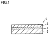
- Fig. 1 is a schematic cross section of a cell structure according to an embodiment of the present disclosure.
- a solid electrolyte layer thus controlled in composition and thickness has a value in resistance reduced to a limit. Then, cell resistance is dominated by a component other than the solid electrolyte layer, that is, a cathode.
- a cell structure has a reduced resistance, and accordingly, a fuel cell provides an increased output.
- a cell structure according to an embodiment of the present disclosure is according to claim 1.
- the cell structure thus has a reduced value in resistance.
- the first metal oxide may be a compound represented by the following formula (1): Al 1 - x B1 x C1 y O 3 - ⁇ ... formula (1), where an element A1 is at least one selected from the group consisting of La, Sm, and Ba, an element B1 is at least one selected from the group consisting of Sr and Ca, an element C1 is at least one selected from the group consisting of Fe, Co, Mn, and Ni, 0 ⁇ x ⁇ 1, 0 ⁇ y ⁇ 1, and ⁇ represents an oxygen vacancy concentration.
- the solid electrolyte layer may include a second metal oxide having a perovskite crystal structure, and the second metal oxide may be a proton conductor represented by the following formula (2): A2 m B2 n C2 1- n O 3 - ⁇ ... formula (2), where an element A2 is at least one selected from the group consisting of Ba, Ca and Sr, an element B2 is at least one selected from the group consisting of Ce and Zr, an element C2 is at least one selected from the group consisting of Y, Yb, Er, Ho, Tm, Gd, In and Sc, 0.85 ⁇ m ⁇ 1, 0.5 ⁇ n ⁇ 1, and ⁇ represents an oxygen vacancy concentration.
- the solid electrolyte layer may have a thickness of 5 ⁇ m or more and 30 ⁇ m or less.
- the cathode may have a thickness of 20 ⁇ m or more and 30 ⁇ m or less. In that case, the cell structure has a further reduced value in resistance.
- an expression in the form of "X to Y” means a range's upper and lower limits (that is, X or more and Y or less), and when X is not accompanied by any unit and Y is alone accompanied by a unit, X has the same unit as Y.
- a cell structure according to the present embodiment includes a cathode, an anode, and a solid electrolyte layer interposed between the cathode and the anode.
- the cathode, the anode and the solid electrolyte layer are for example sintered and thus integrated together.
- the cathode is in the form of a sheet
- the anode is in the form of a sheet
- the solid electrolyte layer is in the form of a sheet
- the solid electrolyte layer is disposed on the anode
- the cathode is disposed on the solid electrolyte layer.
- the cathode's resistance Rc has a high ratio of contribution to the resistance of the cell structure, and the cathode includes a first metal oxide having a perovskite crystal structure.
- the cell structure has a resistance (a cell resistance), which is a sum of reaction resistance and direct-current resistance.
- the cathode has an electrical resistance Rc, which is a sum of the cathode's reaction resistance and the cathode's direct-current resistance R DCc .
- the anode and the solid electrolyte layer have an electrical resistance Ra, which is a sum of the anode's reaction resistance a sum R DCe in direct-current resistance of the anode and the solid electrolyte layer.
- Reaction resistance indicates how difficult it is to cause reaction at the cathode or the anode.
- Reaction resistance is determined for example by alternate-current impedance measurement using a frequency response analyzer (FRA).
- FFA frequency response analyzer
- alternating-current impedance may be measured as follows: at a temperature of 600°C, hydrogen is passed as fuel gas to the anode at a rate of 100 cc/min and oxygen (or air) is passed to the cathode at a rate of 200 cc/min, and frequency is varied between 0.1 Hz to 100 kHz.
- the reaction resistance of the cathode and that of the anode are determined by a Cole-Cole plot of the alternating-current impedance corresponding to each measured frequency.
- a Cole-Cole plot is a graph in which an alternating-current impedance (a real number) corresponding to each frequency is plotted on the x-axis and imaginary impedance is plotted on the y-axis, and it depicts an arc.
- an arc attributed to the reaction resistance of the cathode and an arc attributed to the reaction resistance of the anode are formed. Which arc corresponds to the cathode and which arc corresponds to the anode can be determined by varying the concentration of the gas introduced.
- an arc that becomes large when oxygen introduced to the cathode is reduced in concentration is an arc attributed into the reaction resistance of the cathode.
- an arc that becomes large when hydrogen introduced into the anode is reduced in concentration is an arc due attributed to the reaction resistance of the anode.
- Direct-current resistance is a value in resistance when a direct current is applied to a subject, and it indicates a resistance in a reaction of movement of electrons or the like.
- Direct-current resistance can be calculated as follows: voltage generated when a current having a plurality of predetermined values is passed through a subject is calculated and direct-current resistance is calculated from a gradient of an I-V characteristic represented with a horizontal axis representing the values of the current and a vertical axis representing the voltage.
- Voltage may be measured for example as follows: with the current passed for 60 minutes, and at a temperature of 600°C, hydrogen is passed to the anode as fuel gas at a rate of 100 cc/min and air is passed to the cathode at a rate of 200 cc/min, and the current has a value varying between 0 to 600 mA/cm 2 .
- the direct-current resistance of the cathode or the direct-current resistance of the anode and the solid electrolyte layer can be determined, for example, as follows: A cell structure comprising a cathode including a first metal oxide and having a thickness Tc, an anode having a thickness Ta, and a solid electrolyte layer having a thickness Te is produced. The cell structure's direct-current resistance R DC is measured while the thickness Te of the solid electrolyte layer is changed.
- the anode contains metal nickel as a catalytic component, and accordingly, the direct-current resistance of the anode may be regarded as substantially zero. Furthermore, as the cathode is fixed in thickness, the direct-current resistance of the cathode is also fixed.
- the above measurement clarifies a relationship between the thickness Te of the solid electrolyte layer and the direct-current resistance R DC . From this relationship, the direct-current resistance R DC of the entire cell structure when the thickness Te of the solid electrolyte layer is zero is calculated.
- the calculated value in resistance R DC is a direct-current resistance R DCc of the cathode having the thickness Tc and including the first metal oxide.
- the cathode including the first metal oxide has a thickness set to be larger than 15 ⁇ m and 30 ⁇ m or less.
- the resistance Ra of the anode and the solid electrolyte layer the resistance Rc of the cathode is reduced, and a fuel cell using the cell structure provides output with improved density.
- the cathode has a thickness of 15 ⁇ m or less, it results in an excessively small reaction field and hence an increased reaction resistance.
- gas diffusivity is reduced or electrons travel an increased distance or the like, and direct-current resistance increases.
- the definition of the thickness of the cathode and the like will be described hereinafter.
- the thickness of the cathode significantly affects the cell resistance R when the cathode has a high ratio of contribution to the resistance of the cell structure.
- the relationship between the resistance Rc and the resistance Ra may satisfy Rc/Ra ⁇ 0.35, Rc/Ra ⁇ 0.4, or Rc/Ra ⁇ 0.6. While the upper limit of Rc/Ra is not particularly limited, it may satisfy Rc/Ra ⁇ 1.5, for example.
- the cell resistance R is not particularly limited.
- the cell resistance R is, for example, 0.7 ⁇ • cm 2 to 1.5 ⁇ • cm 2 .
- the resistance Ra of the anode and the solid electrolyte layer is not particularly limited, either.
- the resistance Ra is, for example, 0.1 ⁇ • cm 2 to 0.2 ⁇ • cm 2 .
- the resistance Rc of the cathode is not particularly limited, either.
- the resistance Rc is, for example, 0.5 ⁇ • cm 2 to 1.4 ⁇ • cm 2 .
- the cathode is preferably in the form of a sheet.
- the cathode has a porous structure that can adsorb, dissociate and ionize oxygen molecules.
- the cathode is formed of material which is a first metal oxide having a perovskite crystal structure.
- An oxide having a perovskite crystal structure is represented for example by ABO 3 , and has a crystal structure similar to CaTiO 3 .
- ABO 3 also includes a crystal structure of ABO 3 - ⁇ , where ⁇ represents an oxygen vacancy concentration. Note that an element having a larger ionic radius than the B-site enters the A-site.
- a compound represented by the following formula (1) is preferably indicated as an example, where 0 ⁇ x ⁇ 1, 0 ⁇ y ⁇ 1, and ⁇ represents an oxygen vacancy concentration.
- the element A1 is at least one selected from the group consisting of La, Sm, and Ba.
- the element B1 is at least one selected from the group consisting of Sr and Ca.
- the element C1 is at least one selected from the group consisting of Fe, Co, Mn, and Ni.
- the first metal oxide includes lanthanum strontium cobalt ferrite (LSCF, La 1 - a Sr a Co 1 - b Fe b O 3 - ⁇ , 0 ⁇ a ⁇ 1, 0 ⁇ b ⁇ 1, and ⁇ represents an oxygen vacancy concentration), lanthanum strontium manganite (LSM, La 1 - c Sr c MnO 3 - ⁇ , 0 ⁇ c ⁇ 1, and ⁇ represents an oxygen vacancy concentration), lanthanum strontium cobaltite (LSC, La 1 - d Sr d CoO 3 - ⁇ , 0 ⁇ d ⁇ 1, and ⁇ represents an oxygen vacancy concentration), samarium strontium cobaltite (SSC, Sm 1 - e Sr e CoO 3 - ⁇ , 0 ⁇ e ⁇ 1, and ⁇ represents an oxygen vacancy concentration), and the like.
- LSCF is prefer
- the cathode includes a first metal oxide. While the cathode may include a component other than the first metal oxide, the cathode preferably contains the component in a small amount. For example, it is preferable that 99% by mass or more of the cathode is the first metal oxide. That is, the first metal oxide is contained in the cathode preferably at a ratio of 99% by mass or more and 100% by mass or less.
- the component other than the first metal oxide is not particularly limited, and may be a compound (including a compound which is not ionic conductive) known as a material for a cathode. The ratio of the content of the first metal oxide in the cathode can be determined for example through x-ray diffraction.
- the particle diameter of the first metal oxide is not particularly limited.
- the first metal oxide forming the cathode may have a particle diameter of 0.3 ⁇ m to 5 ⁇ m, 0.5 ⁇ m to 3 ⁇ m, or 1 ⁇ m to 3 ⁇ m.
- the cathode's resistance is more easily reduced.
- the particle diameter of the first metal oxide can be calculated by capturing a photographical image of the cathode in cross section with a scanning electron microscope (SEM). Specifically, initially, in an SEM photographical image of any cross section S of the cathode, a region Rg including ten or more granules is determined.
- the region Rg may for example be a region of 50 ⁇ m ⁇ 30 ⁇ m. Five granules are arbitrarily selected from the region Rg, and their respective maximum diameters are obtained.
- the "maximum diameter" of the granule is a distance between two points on the circumference of the granule in the cross section S that is a maximum distance.
- These maximum diameters' average value is defined as the particle diameter of the first metal oxide in the cross section S.
- the first metal oxide's particle diameters in any cross sections at four other locations are calculated.
- the first metal oxide's particle diameters in cross sections at these five locations are averaged to obtain a value, which serves as the particle diameter of the first metal oxide.
- the cathode may include a catalyst such as nickel, iron, cobalt, or the like.
- the catalyst may be a simple metal or a metal oxide.
- the catalyst's composition can be estimated through energy dispersive x-ray spectroscopy accompanying an SEM (SEM-EDX) and x-ray diffraction combined together.
- SEM-EDX SEM-EDX
- the cathode including the catalyst is formed by mixing and sintering the catalyst and the first metal oxide.
- the cathode When the cathode is in the form of a sheet, the cathode is not particularly limited in thickness, although it is preferably larger than 15 ⁇ m and 30 ⁇ m or less, more preferably 20 ⁇ m or more and 30 ⁇ m or less. When the cathode has a thickness falling within this range, the cathode's internal resistance is more easily reduced. Note that when the cathode is in the form of a sheet, the cathode's "thickness" means a shortest distance between one major surface of the cathode and the other major surface of the cathode. The same applies to the thickness of the solid electrolyte layer and the thickness of the anode described later.
- the thickness of the cathode can also be calculated by capturing a photographical image of the cathode in cross section with an SEM. Specifically, initially, in an SEM photographical image of any cross section S of the cathode, an average value in thickness at any five points is obtained. This is defined as a thickness of the cathode in section S. Similarly, the cathode's values in thickness in any cross sections at four other locations are calculated. The cathode's values in thickness in cross section at these five locations are averaged to obtain a value, which serves as the thickness of the cathode. The thickness of the solid electrolyte layer and the thickness of the anode are similarly determined.
- the solid electrolyte layer includes an ion-conductive metal oxide.
- the ions that move through the solid electrolyte layer are not particularly limited, and may be oxide ions or may be hydrogen ions (protons).
- the metal oxide is proton-conductive, the solid electrolyte layer transfers protons generated at the anode to the cathode.
- the metal oxide is oxygen ion-conductive, the solid electrolyte layer transfers oxygen ions generated at the cathode to the anode.
- the solid electrolyte layer is preferably proton conductive.
- a proton conductive fuel cell (PCFC) can operate, for example, in a medium temperature range of 400°C to 600°C. The PCFC can thus be used in various applications.
- the solid electrolyte layer is oxygen ion-conductive, the PCFC can operate in a temperature range of 800°C or lower.
- the element A2 is at least one selected from the group consisting of barium (Ba), calcium (Ca), and strontium (Sr). Inter alia, the element A2 preferably includes Ba from the viewpoint of proton conductivity.
- the element B2 is at least one selected from the group consisting of cerium (Ce) and zirconium (Zr). Inter alia, the element B2 preferably includes Zr from the viewpoint of proton conductivity.
- the element C2 is at least one selected from the group consisting of yttrium (Y), ytterbium (Yb), erbium (Er), holmium (Ho), thulium (Tm), gadolinium (Gd), indium (In), and scandium (Sc).
- the element C2 preferably includes Y from the viewpoint of proton conductivity and chemical stability.
- BZY is preferably a compound represented by BaZr 1 - f Y f O 3 - ⁇ (0 ⁇ f ⁇ 0.5, BZY), BaCe 1 - g Y g O 3 - ⁇ (0 ⁇ g ⁇ 0.5, BCY) and their solid solution or BaZr 1 - h-i Ce h Y i O 3 - ⁇ (0 ⁇ h ⁇ 1, 0 ⁇ i ⁇ 0.5, BZCY) as it is particularly excellently proton conductive and exhibits high power generation performance.
- BZY is preferable. A part of Y that occupies the B site may be replaced with another element (e.g., another lanthanoid element), and a part of Ba that occupies the A site may be replaced with another group-2 element (Sr, Ca, or the like).
- the solid electrolyte layer preferably includes a second metal oxide. While the solid electrolyte layer may contain a component other than the second metal oxide, the former preferably contains the latter in a small amount. For example, it is preferable that 99% by mass or more of the solid electrolyte layer is the second metal oxide. That is, the second metal oxide is contained in the solid electrolyte layer preferably at a ratio of 99% by mass or more and 100% by mass or less.
- the component other than the second metal oxide is not particularly limited, and can include a compound (including a compound which is not ionic conductive) known as solid electrolyte. The ratio of the content of the second metal oxide in the solid electrolyte layer can be determined for example through x-ray diffraction as set forth above.
- the solid electrolyte layer When the solid electrolyte layer is in the form of a sheet, the solid electrolyte layer preferably has a thickness of 3 ⁇ m to 50 ⁇ m, more preferably 5 ⁇ m to 30 ⁇ m, particularly preferably 5 ⁇ m to 20 ⁇ m. When the solid electrolyte layer has a thickness in such a range, the solid electrolyte layer's resistance is suppressed to be low.
- the ratio of the thickness Te of the solid electrolyte layer and the thickness Ta of the anode, or Ta/Te may be 10 or more. Thus, when the anode is sufficiently thick relative to the solid electrolyte layer, the solid electrolyte layer can be supported by the anode.
- the solid electrolyte layer may be a stack of a plurality of solid electrolyte layers.
- each solid electrolyte layer may include the second metal oxide different or identical in type.
- the solid electrolyte layer may for example be a stack of a layer including BZY and a layer including BCY, or a stack of a layer including BZY and a layer including BZCY. In those cases, the stacked layers have close thermal expansion coefficients, which more likely suppresses the cell structure's warpage and deformation.
- the cathode and the anode together with the solid electrolyte layer including the second metal oxide (i.e., a first solid electrolyte layer), there may be a layer including a metal oxide other than the second metal oxide (i.e., a second solid electrolyte layer).
- a metal oxide other than the second metal oxide is an oxygen ion-conductive metal oxide.
- a compound including zirconium dioxide hereinafter referred to as a "zirconium compound”
- a compound including lanthanum and gallium hereinafter referred to as a “lanthanum gallate”
- a compound including cerium hereinafter referred to as a "ceria compound”
- the ceria compound can include gadolinium-doped ceria (GDC), samarium-doped ceria (SDC), yttrium-doped ceria (YDC), and lanthanum-doped ceria (LDC).
- GDC gadolinium-doped ceria
- SDC samarium-doped ceria
- YDC yttrium-doped ceria
- LDC lanthanum-doped ceria
- the anode has an ion-conductive porous structure.
- a reaction to oxidize a fuel such as hydrogen introduced through a fuel channel and release protons and electrons is performed.
- the anode can be formed of a material for example known as a material used for an anode of a fuel cell. Specifically, it includes a compound including nickel serving as a catalytic component (hereinafter referred to as a "Ni compound”), a composite oxide obtained from the Ni compound and a third metal oxide, or the like.
- Ni compound a compound including nickel serving as a catalytic component
- the anode including the composite oxide can be formed for example by mixing and sintering powdery NiO and the third metal oxide provided in the form of powder or the like.
- the second metal oxide used as a material for the solid electrolyte layer can be indicated as an example.
- the ratio of the content of the nickel compound (or Ni compound) in the material for the anode is, for example, 40 to 90% by mass, and may be 60 to 90% by mass.
- the anode When the anode is in the form of a sheet, the anode is not particularly limited in thickness.
- the anode may have a thickness for example of 10 ⁇ m to 2 mm or 10 ⁇ m to 100 ⁇ m.
- the anode's thickness can be selected for example from a range of 100 ⁇ m to 2 mm, as appropriate.
- Fig. 1 is a cross section of the cell structure according to the present embodiment. While Fig. 1 shows a cell structure 1 in the form of a stack of layers, cell structure 1 is not limited thereto in shape. For example, it may be rolled with anode 3 inside to have a cylindrical shape so as to be hollow. The cylindrical shape has a hollow central portion and has anode 3, solid electrolyte layer 4, and cathode 2 successively, concentrically arranged as viewed from the inside (not shown). In the example shown in Fig. 1 , anode 3 is larger in thickness than cathode 2, and functions as a support for supporting solid electrolyte layer 4 (and hence cell structure 1).
- the cell structure can be manufactured in a method for example comprising: a first step of preparing a material for a solid electrolyte layer, a material for an anode and a material for a cathode; a second step of forming a first layer including the material for the anode and a second layer including the material for the solid electrolyte layer on a surface of the first layer, and firing the first and second layers; and a third step of disposing and firing a layer including the material for the cathode on a surface of the formed solid electrolyte layer.
- a method for example comprising: a first step of preparing a material for a solid electrolyte layer, a material for an anode and a material for a cathode; a second step of forming a first layer including the material for the anode and a second layer including the material for the solid electrolyte layer on a surface of the first layer, and firing the first and second layers; and a third step of disposing and
- a material for the solid electrolyte layer, a material for the anode, and a material for the cathode are prepared.
- the material for the solid electrolyte layer and the material for the anode preferably include a binder from the viewpoint of shapability.
- the binder includes known materials used in producing ceramic materials, e.g., polymer binders such as cellulose derivatives (cellulose ethers) such as ethyl cellulose, vinyl acetate resins (including saponified vinyl acetate resins such as polyvinyl alcohol), and acrylic resins; and waxes such as paraffin wax.
- the material for the anode When the material for the anode is subjected to press forming, the material for the anode includes the binder in an amount for example of 1 to 15 parts by mass (3 to 10 parts by mass in particular) relative to 100 parts by mass of the above composite oxide (or 100 parts by mass of the above Ni compound). Otherwise, the binder is included in an amount for example of 1 to 20 parts by mass (1.5 to 15 parts by mass in particular).
- the material for the solid electrolyte layer includes the binder in an amount for example of 1 to 20 parts by mass (1.5 to 15 parts by mass in particular) relative to 100 parts by mass of the second metal oxide.
- Each material may include a dispersion medium such as water and/or an organic solvent (e.g., hydrocarbons such as toluene (aromatic hydrocarbons); alcohols such as ethanol and isopropanol; and carbitols such as butyl carbitol acetate), as necessary.
- a dispersion medium such as water and/or an organic solvent (e.g., hydrocarbons such as toluene (aromatic hydrocarbons); alcohols such as ethanol and isopropanol; and carbitols such as butyl carbitol acetate), as necessary.
- an organic solvent e.g., hydrocarbons such as toluene (aromatic hydrocarbons); alcohols such as ethanol and isopropanol; and carbitols such as butyl carbitol acetate
- additives such as a surfactant, a deflocculant (such as polycarboxylic acid), and the like, as necessary.
- a first layer including the material for the anode and a second layer including the material for the solid electrolyte layer are stacked and the stack is fired.
- the first layer can also be understood as a precursor for the anode.
- the second layer can also be understood as a precursor for the solid electrolyte layer.
- Each layer may be formed in any method that is selected depending on the layer's desired thickness, as appropriate. For example, when a layer having a thickness of several hundreds ⁇ m or more is formed, each material can be shaped by press forming, tape casting, or the like. When a layer having a thickness of several ⁇ m to several hundreds ⁇ m is formed, each material can be shaped in an existing method such as screen printing, spray coating, spin coating, dip coating and the like. The stack of layers may be formed by combining these methods. The second layer is typically formed by screen printing, spray coating, spin coating, dip coating, or the like.
- the material for the anode is formed into a predetermined shape by press forming.
- the predetermined shape is, for example, in the form of a pellet, a plate, a sheet, or the like.
- the material for the anode may be granulated and then shaped. If necessary, the obtained granules may be disintegrated and then shaped.
- the material for the solid electrolyte layer is applied to a surface of the shaped first layer for example by screen printing, spray coating, spin coating, dip coating, or the like to form a second layer.
- a stack of layers is thus obtained.
- a step of calcining (or provisionally sintering) the first layer may be performed.
- Calcination may be performed at a temperature lower than a temperature at which the material for the anode is sintered (e.g., 900°C to 1100°C). Calcination facilitates applying the material for the solid electrolyte layer.
- the obtained stack of layers is fired. This is done by heating the obtained stack in an oxygen-containing atmosphere for example to 1200°C to 1700°C.
- the firing atmosphere's oxygen content is not particularly limited.
- the firing may be performed for example in an air atmosphere (oxygen content: about 20% by volume) or in pure oxygen (oxygen content: 100% by volume).
- the firing can be performed at a normal pressure or a high pressure.
- a resin component such as a binder included in each material may be removed. That is, after the material for the solid electrolyte layer is applied, the stack of layers is heated in the air to a relatively low temperature of about 500°C to 700°C to remove a resin component included in each material. Thereafter, the above-described firing is performed.
- the first and second layers are co-sintered.
- the anode and the solid electrolyte layer are thus formed to be integrated.
- a layer including the material for the cathode is disposed on a surface of the formed solid electrolyte layer and fired.
- the cathode is thus formed.
- the firing is performed in an oxygen-containing atmosphere similar the above for example at 800 to 1100°C.
- the material for the cathode may be disposed on a surface of the solid electrolyte layer by using a cathode dispersion such as paste or slurry mixed with a binder or the like.
- the cathode dispersion is disposed for example in the same method as that described above.
- the cathode dispersion includes the binder in an amount for example of 1 to 15 parts by mass (3 to 10 parts by mass, in particular) relative to 100 parts by mass of the first metal oxide. Otherwise, the binder is included in an amount for example of 1 to 20 parts by mass (1.5 to 15 parts by mass in particular).
- a cell structure comprising:
- a cell structure was produced in the following procedure: Initially, NiO was mixed with BZY (BaZr 0.8 Y 0.2 O 2.9 ) so that 70% by mass of Ni (a catalytic component) was included, and the mixture was disintegrated and kneaded by a ball mill. The obtained powder was press-formed to form a compact (thickness: 550 ⁇ m) constituting the anode, and the compact was provisionally sintered at 1000°C. Subsequently, a paste of a mixture of BZY (BaZr 0.8 Y 0.2 O 2.9 ) and a water-soluble binder resin (ethylcellulose) was applied to one surface of the compact by screen printing.
- BZY BaZr 0.8 Y 0.2 O 2.9
- a water-soluble binder resin ethylcellulose
- the compact with the paste applied thereto was heated to 750°C to remove the water-soluble binder resin. Subsequently, in an oxygen atmosphere, a heat treatment is performed at 1400°C to perform co-sintering to thus form an anode and a solid electrolyte layer (thickness: 10 ⁇ m).
- an LSCF paste of a mixture of powder of LSCF (La 0.6 Sr 0.4 Co 0.2 Fe 0.8 O 3 - ⁇ ) serving as the material for the cathode and the above-mentioned water-soluble binder resin is screen-printed on the compact at a surface of the solid electrolyte layer.
- the compact with the LSCF paste screen-printed thereon was fired in an oxygen atmosphere at 1000°C for 2 hours to produce a cell structure.
- a cross section of the cell structure was imaged with an SEM, and the above described method was employed to calculate the thickness of the cathode and the particle diameter of the LSCF included in the cathode.
- the cathode had a thickness of 16.0 ⁇ m, and the LSCF included in the cathode had a particle diameter of 0.5 ⁇ m.
- a current collector composed of a porous nickel material (manufactured by Sumitomo Electric Industries, Ltd., Celmet, thickness: 1 mm, porosity: 95% by volume) was disposed on a surface of each cell structure obtained as described above. Further, a separator formed of stainless steel and having a channel was disposed on each current collector to produce a fuel cell A.
- a lead wire had one end bonded to each current collector. The lead wire had the other end drawn out of the fuel cell and connected to a measuring instrument so that a value of a current and a value of a voltage between each lead wire and another can be measured.
- the fuel cell A's operating temperature (or reduction temperature) was set at 700°C, and hydrogen was passed to the anode as fuel gas at a rate of 100 cc/min and air was passed to the cathode at a rate of 200 cc/min to reduce NiO included in the anode.
- the cell structure's direct-current resistance and reaction resistance were measured, and the above-described method was employed to calculate the cathode's resistance Rc and the anode and solid electrolyte layer's resistance Ra.
- Rc/Ra equals 0.41.
- Table 1 shows a result.
- a cell structure B and a fuel cell B were produced and evaluated in the same manner as in Example 1 except that the cathode had a thickness of 24.0 ⁇ m.LSCF included in the cathode had a particle diameter of 0.9 ⁇ m.Rc/Ra equals 0.38.
- a cell structure C and a fuel cell C were produced and evaluated in the same manner as in Example 1 except that the cathode had a thickness of 28.5 ⁇ m.LSCF included in the cathode had a particle diameter of 0.6 ⁇ m.Rc/Ra equals 0.39.
- a cell structure a and a fuel cell a were produced and evaluated in the same manner as in Example 1 except that the cathode had a thickness of 11.5 ⁇ m.
- LSCF included in the cathode had a particle diameter of 0.8 ⁇ m.
- Rc/Ra equals 0.41.
- a cell structure b and a fuel cell b were produced and evaluated in the same manner as in Example 1 except that the cathode had a thickness of 15.0 ⁇ m.LSCF included in the cathode had a particle diameter of 1.1 ⁇ m.Rc/Ra equals 0.44.
- a cell structure c and a fuel cell c were produced and evaluated in the same manner as in Example 1 except that the cathode had a thickness of 30.5 ⁇ m.LSCF included in the cathode had a particle diameter of 0.8 ⁇ m.Rc/Ra equals 0.43.
- Examples 1 to 3 and Comparative Examples 1 to 3 each had a cathode including LSCF having a different particle diameter due to differences in conditions for production, such as distribution in particle size of LSCF powder serving as a source material, distribution in temperature inside an electric furnace used for firing, and how LSCF powder dispersed in the LSCF paste.
- Table 1 fuel cell thickness of cathode ( ⁇ m) maximum power density (mW/cm 2 ) a 11.5 220.9 b 15.0 280.3 A 16.0 321.5 B 24.0 428.9 C 28.5 339.0 c 30.5 176.8
Landscapes
- Chemical & Material Sciences (AREA)
- Engineering & Computer Science (AREA)
- Electrochemistry (AREA)
- General Chemical & Material Sciences (AREA)
- Chemical Kinetics & Catalysis (AREA)
- Manufacturing & Machinery (AREA)
- Life Sciences & Earth Sciences (AREA)
- Sustainable Energy (AREA)
- Sustainable Development (AREA)
- Materials Engineering (AREA)
- Organic Chemistry (AREA)
- General Life Sciences & Earth Sciences (AREA)
- Geology (AREA)
- Inorganic Chemistry (AREA)
- Physics & Mathematics (AREA)
- Thermal Sciences (AREA)
- Ceramic Engineering (AREA)
- Fuel Cell (AREA)
- Inert Electrodes (AREA)
Claims (5)
- Zellstruktur, umfassend:eine Kathode;eine Anode; undeine Festelektrolytschicht, die zwischen der Kathode und der Anode eingefügt ist,wobei die Kathode in Form eines Blatts ist,die Anode in Form eines Blatts ist,die Festelektrolytschicht in Form eines Blatts ist,die Festelektrolytschicht auf der Anode angeordnet ist,die Kathode auf der Festelektrolytschicht angeordnet ist,die Kathode einen Widerstand Rc aufweist, die Anode und die Festelektrolytschicht einen Widerstand Ra aufweisen, wobei der Widerstand Rc und der Widerstand Ra eine Beziehung von Rc/Ra ≥ 0,3 erfüllen, die Widerstände wie in der Beschreibung definiert gemessen werden,die Kathode ein erstes Metalloxid mit einer Perovskit-Kristallstruktur beinhaltet,die Kathode eine Dicke größer als 15 µm und gleich oder kleiner als 30 µm aufweist.
- Zellstruktur gemäß Anspruch 1, wobei das erste Metalloxid durch die folgende Formel (1) repräsentiert wird:
A11-xB1xC1yO3-δ Formel (1),
wobei ein Element A1 zumindest eins ist, das ausgewählt wird aus der Gruppe, die aus La, Sm und Ba besteht, ein Element B1 zumindest eins ist, das ausgewählt wird aus der Gruppe, die aus Sr und Ca besteht, ein Element C1 zumindest eins ist, das ausgewählt wird aus der Gruppe, die aus Fe, Co, Mn und Ni besteht, 0 < x < 1, 0 < y ≤ 1, and δ eine Sauerstoffvakanz-Konzentration repräsentiert. - Zellstruktur gemäß Anspruch 1 oder 2, wobeidie Festelektrolytschicht ein zweites Metalloxid mit einer Perovskit-Kristallstruktur beinhaltet, unddas zweite Metalloxid ein Protonenleiter ist, der durch die folgende Formel (2) repräsentiert wird
A2mB2nC21-nO3-δ Formel (2),
wobei ein Element A2 zumindest eins ist, das ausgewählt wird aus der Gruppe, die aus Ba, Ca und Sr besteht, ein Element B2 zumindest eins ist, das ausgewählt wird aus der Gruppe, die aus Ce und Zr besteht, ein Element C2 zumindest eins ist, das ausgewählt wird aus der Gruppe, die aus Y, Yb, Er, Ho, Tm, Gd, In und Sc besteht, 0,85 ≤ m ≤ 1, 0,5 ≤ n n < 1, and δ eine Sauerstoffvakanz-Konzentration repräsentiert. - Zellstruktur gemäß einem der Ansprüche 1 bis 3, wobei die Festelektrolytschicht eine Dicke von 5 µm oder mehr und 30 µm oder weniger aufweist.
- Zellstruktur gemäß einem der Ansprüche 1 bis 4, wobei die Kathode eine Dicke von 20 µm oder mehr und 30 µm oder weniger aufweist.
Applications Claiming Priority (2)
| Application Number | Priority Date | Filing Date | Title |
|---|---|---|---|
| JP2018039521 | 2018-03-06 | ||
| PCT/JP2019/005492 WO2019171905A1 (ja) | 2018-03-06 | 2019-02-15 | セル構造体 |
Publications (3)
| Publication Number | Publication Date |
|---|---|
| EP3764447A1 EP3764447A1 (de) | 2021-01-13 |
| EP3764447A4 EP3764447A4 (de) | 2021-12-08 |
| EP3764447B1 true EP3764447B1 (de) | 2025-06-18 |
Family
ID=67846576
Family Applications (1)
| Application Number | Title | Priority Date | Filing Date |
|---|---|---|---|
| EP19763876.0A Active EP3764447B1 (de) | 2018-03-06 | 2019-02-15 | Zellstruktur |
Country Status (5)
| Country | Link |
|---|---|
| US (1) | US20210066728A1 (de) |
| EP (1) | EP3764447B1 (de) |
| JP (1) | JP7136185B2 (de) |
| CN (2) | CN119965311A (de) |
| WO (1) | WO2019171905A1 (de) |
Families Citing this family (1)
| Publication number | Priority date | Publication date | Assignee | Title |
|---|---|---|---|---|
| US20220393185A1 (en) * | 2021-05-28 | 2022-12-08 | Seeo2 Energy Inc. | Electrical contact material for integration as a contact layer in a reversible solid-oxide fuel cell |
Family Cites Families (23)
| Publication number | Priority date | Publication date | Assignee | Title |
|---|---|---|---|---|
| JP2604437B2 (ja) * | 1987-10-15 | 1997-04-30 | 東燃株式会社 | 高温型燃料電池用電極間接合体及び高温型燃料電池用カソード集電体 |
| JP3843766B2 (ja) * | 2000-07-04 | 2006-11-08 | 日産自動車株式会社 | 固体電解質型燃料電池 |
| JP2002170579A (ja) * | 2000-09-22 | 2002-06-14 | Nissan Motor Co Ltd | 固体電解質型燃料電池 |
| EP1369949B1 (de) * | 2002-06-06 | 2013-01-30 | Panasonic Corporation | Festelektrolytbrennstoffzelle und Verfahren zu ihrer Herstellung |
| JP2005044663A (ja) * | 2003-07-23 | 2005-02-17 | Sony Corp | 固体電解質、リチウムイオン電池及びその製造方法 |
| CN101295791B (zh) * | 2007-04-24 | 2011-01-26 | 中国科学院大连化学物理研究所 | 一种中、低温固体氧化物燃料电池三元复合阴极材料 |
| KR20120080375A (ko) * | 2011-01-07 | 2012-07-17 | 삼성전자주식회사 | 연료전지용 양극 소재, 이를 포함하는 연료전지용 양극과 그 양극의 제조방법, 및 고체산화물 연료전지 |
| JP2012227142A (ja) * | 2011-04-19 | 2012-11-15 | Samsung Electronics Co Ltd | 燃料電池用正極材料、これを含む燃料電池用正極および固体酸化物形燃料電池 |
| CN102394180B (zh) * | 2011-07-18 | 2014-06-04 | 四川安科特电子科技有限公司 | 一种片式有机固体电解质电解电容器的制备方法 |
| WO2014010042A1 (ja) * | 2012-07-11 | 2014-01-16 | トヨタ自動車株式会社 | 全固体電池の製造方法 |
| US9496559B2 (en) * | 2012-08-07 | 2016-11-15 | Atomic Energy Council-Institute Of Nuclear Energy Research | Method for manufacturing solid oxide fuel cell anode with high stability and high efficiency |
| CN103682388A (zh) * | 2012-09-17 | 2014-03-26 | 中国科学院上海硅酸盐研究所 | 平板固体氧化物燃料电池电解质真空浸渍镀膜方法及装置 |
| JP2014071937A (ja) * | 2012-09-27 | 2014-04-21 | Kikusui Chemical Industries Co Ltd | 直接火炎型燃料電池単セル及びその製造方法 |
| CN103872367B (zh) * | 2012-12-13 | 2016-09-07 | 中国科学院大连化学物理研究所 | 一种固体氧化物燃料电池氧化锆基电解质薄膜 |
| JP6151212B2 (ja) * | 2014-04-22 | 2017-06-21 | 株式会社ノリタケカンパニーリミテド | 低温作動型の固体酸化物形燃料電池およびその製造方法 |
| JP2016054146A (ja) * | 2014-09-02 | 2016-04-14 | Toto株式会社 | 固体酸化物形燃料電池システム |
| WO2016076078A1 (ja) | 2014-11-13 | 2016-05-19 | 住友電気工業株式会社 | セル構造体、その製造方法、および、燃料電池 |
| JP6398647B2 (ja) | 2014-11-21 | 2018-10-03 | 住友電気工業株式会社 | 固体酸化物型燃料電池用アノードの製造方法および燃料電池用電解質層−電極接合体の製造方法 |
| JP6601488B2 (ja) * | 2015-03-30 | 2019-11-06 | 住友電気工業株式会社 | プロトン伝導体、燃料電池用固体電解質層、セル構造体およびそれを備える燃料電池 |
| JP2017117663A (ja) | 2015-12-24 | 2017-06-29 | アイシン精機株式会社 | 固体酸化物型電池セル及びその評価装置 |
| JP7089838B2 (ja) | 2016-01-05 | 2022-06-23 | 株式会社日本触媒 | 固体酸化物形燃料電池用単セル及びその製造方法、並びに、固体酸化物形燃料電池用カソード及びその製造方法 |
| JP6041173B2 (ja) | 2016-01-25 | 2016-12-07 | 住友電気工業株式会社 | 電解質複合部材、電解質/電極複合部材 |
| JP6688704B2 (ja) | 2016-09-06 | 2020-04-28 | 大森機械工業株式会社 | 包装装置 |
-
2019
- 2019-02-15 EP EP19763876.0A patent/EP3764447B1/de active Active
- 2019-02-15 US US16/977,156 patent/US20210066728A1/en not_active Abandoned
- 2019-02-15 WO PCT/JP2019/005492 patent/WO2019171905A1/ja not_active Ceased
- 2019-02-15 CN CN202510132745.1A patent/CN119965311A/zh active Pending
- 2019-02-15 CN CN201980016535.9A patent/CN111801826A/zh active Pending
- 2019-02-15 JP JP2020504887A patent/JP7136185B2/ja active Active
Also Published As
| Publication number | Publication date |
|---|---|
| US20210066728A1 (en) | 2021-03-04 |
| EP3764447A1 (de) | 2021-01-13 |
| WO2019171905A1 (ja) | 2019-09-12 |
| CN119965311A (zh) | 2025-05-09 |
| JPWO2019171905A1 (ja) | 2021-02-12 |
| JP7136185B2 (ja) | 2022-09-13 |
| CN111801826A (zh) | 2020-10-20 |
| EP3764447A4 (de) | 2021-12-08 |
Similar Documents
| Publication | Publication Date | Title |
|---|---|---|
| EP3279987B1 (de) | Protonenleiter, brennstoffzellenfestelektrolytschicht, zellenstruktur und brennstoffzelle damit | |
| US10734665B2 (en) | Method for producing cell structure | |
| EP3223350B1 (de) | Anode für eine festoxidbrennstoffzelle und herstellungsverfahren dafür sowie herstellungsverfahren für elektrolytschichtelektrodenanordnung für eine brennstoffzelle | |
| KR20130099704A (ko) | 고체산화물 연료전지용 기능층 소재, 및 상기 소재를 이용하여 제조된 기능층과 상기 기능층을 포함하는 고체산화물 연료전지 | |
| US10505196B2 (en) | Solid oxide fuel cell and method for producing electrolyte layer-anode assembly | |
| JP6573243B2 (ja) | 空気極組成物、空気極およびこれを含む燃料電池 | |
| Lai et al. | Production of La0. 6Sr0. 4Co0. 2Fe0. 8O3-δ cathode with graded porosity for improving proton-conducting solid oxide fuel cells | |
| EP3764447B1 (de) | Zellstruktur | |
| JP6664132B2 (ja) | 多孔質構造体とその製造方法、及びそれを用いた電気化学セルとその製造方法 | |
| WO2021256221A1 (ja) | プロトン伝導型セル構造体、プロトン伝導体、電気化学デバイス、及びプロトン伝導体の製造方法 | |
| KR102111859B1 (ko) | 고체산화물 연료 전지 및 이를 포함하는 전지 모듈 | |
| JP2003217597A (ja) | 固体電解質型燃料電池 | |
| WO2020004333A1 (ja) | 固体酸化物形セル用電極及びそれを用いた固体酸化物形セル | |
| EP3764448B9 (de) | Elektrolytschichtanoden-verbundelement und zellstruktur | |
| JP7107875B2 (ja) | 燃料極-固体電解質層複合体の製造方法 | |
| EP3211703A1 (de) | Brennstoffzelle | |
| CN111819720B (zh) | 燃料电池用电解质层-阳极复合部件、电池结构体、燃料电池以及复合部件的制造方法 | |
| KR101257431B1 (ko) | 막-전극 어셈블리, 이의 제조 방법 및 상기 막-전극 어셈블리를 포함하는 스택 및 고체 산화물 연료전지 | |
| KR20200105173A (ko) | 고체산화물 연료전지용 공기극, 이를 포함하는 고체산화물 연료 전지, 이를 포함하는 전지모듈 및 고체산화물 연료전지의 제조방법 |
Legal Events
| Date | Code | Title | Description |
|---|---|---|---|
| STAA | Information on the status of an ep patent application or granted ep patent |
Free format text: STATUS: THE INTERNATIONAL PUBLICATION HAS BEEN MADE |
|
| PUAI | Public reference made under article 153(3) epc to a published international application that has entered the european phase |
Free format text: ORIGINAL CODE: 0009012 |
|
| STAA | Information on the status of an ep patent application or granted ep patent |
Free format text: STATUS: REQUEST FOR EXAMINATION WAS MADE |
|
| 17P | Request for examination filed |
Effective date: 20200812 |
|
| AK | Designated contracting states |
Kind code of ref document: A1 Designated state(s): AL AT BE BG CH CY CZ DE DK EE ES FI FR GB GR HR HU IE IS IT LI LT LU LV MC MK MT NL NO PL PT RO RS SE SI SK SM TR |
|
| AX | Request for extension of the european patent |
Extension state: BA ME |
|
| DAV | Request for validation of the european patent (deleted) | ||
| DAX | Request for extension of the european patent (deleted) | ||
| A4 | Supplementary search report drawn up and despatched |
Effective date: 20211108 |
|
| RIC1 | Information provided on ipc code assigned before grant |
Ipc: H01M 8/1253 20160101ALI20211102BHEP Ipc: H01M 4/90 20060101ALI20211102BHEP Ipc: H01M 4/88 20060101ALI20211102BHEP Ipc: H01M 8/1231 20160101ALI20211102BHEP Ipc: H01M 8/1246 20160101ALI20211102BHEP Ipc: H01M 4/86 20060101ALI20211102BHEP Ipc: H01M 8/1213 20160101AFI20211102BHEP |
|
| GRAP | Despatch of communication of intention to grant a patent |
Free format text: ORIGINAL CODE: EPIDOSNIGR1 |
|
| STAA | Information on the status of an ep patent application or granted ep patent |
Free format text: STATUS: GRANT OF PATENT IS INTENDED |
|
| INTG | Intention to grant announced |
Effective date: 20250120 |
|
| P01 | Opt-out of the competence of the unified patent court (upc) registered |
Free format text: CASE NUMBER: APP_16034/2025 Effective date: 20250402 |
|
| GRAS | Grant fee paid |
Free format text: ORIGINAL CODE: EPIDOSNIGR3 |
|
| GRAA | (expected) grant |
Free format text: ORIGINAL CODE: 0009210 |
|
| STAA | Information on the status of an ep patent application or granted ep patent |
Free format text: STATUS: THE PATENT HAS BEEN GRANTED |
|
| AK | Designated contracting states |
Kind code of ref document: B1 Designated state(s): AL AT BE BG CH CY CZ DE DK EE ES FI FR GB GR HR HU IE IS IT LI LT LU LV MC MK MT NL NO PL PT RO RS SE SI SK SM TR |
|
| REG | Reference to a national code |
Ref country code: GB Ref legal event code: FG4D |
|
| REG | Reference to a national code |
Ref country code: CH Ref legal event code: EP |
|
| REG | Reference to a national code |
Ref country code: DE Ref legal event code: R096 Ref document number: 602019071275 Country of ref document: DE |
|
| REG | Reference to a national code |
Ref country code: CH Ref legal event code: EP |
|
| REG | Reference to a national code |
Ref country code: IE Ref legal event code: FG4D |
|
| PG25 | Lapsed in a contracting state [announced via postgrant information from national office to epo] |
Ref country code: FI Free format text: LAPSE BECAUSE OF FAILURE TO SUBMIT A TRANSLATION OF THE DESCRIPTION OR TO PAY THE FEE WITHIN THE PRESCRIBED TIME-LIMIT Effective date: 20250618 |
|
| REG | Reference to a national code |
Ref country code: LT Ref legal event code: MG9D |
|
| PG25 | Lapsed in a contracting state [announced via postgrant information from national office to epo] |
Ref country code: NO Free format text: LAPSE BECAUSE OF FAILURE TO SUBMIT A TRANSLATION OF THE DESCRIPTION OR TO PAY THE FEE WITHIN THE PRESCRIBED TIME-LIMIT Effective date: 20250918 Ref country code: GR Free format text: LAPSE BECAUSE OF FAILURE TO SUBMIT A TRANSLATION OF THE DESCRIPTION OR TO PAY THE FEE WITHIN THE PRESCRIBED TIME-LIMIT Effective date: 20250919 |
|
| PG25 | Lapsed in a contracting state [announced via postgrant information from national office to epo] |
Ref country code: BG Free format text: LAPSE BECAUSE OF FAILURE TO SUBMIT A TRANSLATION OF THE DESCRIPTION OR TO PAY THE FEE WITHIN THE PRESCRIBED TIME-LIMIT Effective date: 20250618 |
|
| PG25 | Lapsed in a contracting state [announced via postgrant information from national office to epo] |
Ref country code: HR Free format text: LAPSE BECAUSE OF FAILURE TO SUBMIT A TRANSLATION OF THE DESCRIPTION OR TO PAY THE FEE WITHIN THE PRESCRIBED TIME-LIMIT Effective date: 20250618 |
|
| PG25 | Lapsed in a contracting state [announced via postgrant information from national office to epo] |
Ref country code: RS Free format text: LAPSE BECAUSE OF FAILURE TO SUBMIT A TRANSLATION OF THE DESCRIPTION OR TO PAY THE FEE WITHIN THE PRESCRIBED TIME-LIMIT Effective date: 20250918 |
|
| REG | Reference to a national code |
Ref country code: NL Ref legal event code: MP Effective date: 20250618 |
|
| PG25 | Lapsed in a contracting state [announced via postgrant information from national office to epo] |
Ref country code: LV Free format text: LAPSE BECAUSE OF FAILURE TO SUBMIT A TRANSLATION OF THE DESCRIPTION OR TO PAY THE FEE WITHIN THE PRESCRIBED TIME-LIMIT Effective date: 20250618 |
|
| PG25 | Lapsed in a contracting state [announced via postgrant information from national office to epo] |
Ref country code: NL Free format text: LAPSE BECAUSE OF FAILURE TO SUBMIT A TRANSLATION OF THE DESCRIPTION OR TO PAY THE FEE WITHIN THE PRESCRIBED TIME-LIMIT Effective date: 20250618 |
|
| PG25 | Lapsed in a contracting state [announced via postgrant information from national office to epo] |
Ref country code: PT Free format text: LAPSE BECAUSE OF FAILURE TO SUBMIT A TRANSLATION OF THE DESCRIPTION OR TO PAY THE FEE WITHIN THE PRESCRIBED TIME-LIMIT Effective date: 20251020 |
|
| REG | Reference to a national code |
Ref country code: AT Ref legal event code: MK05 Ref document number: 1805061 Country of ref document: AT Kind code of ref document: T Effective date: 20250618 |
|
| PG25 | Lapsed in a contracting state [announced via postgrant information from national office to epo] |
Ref country code: IS Free format text: LAPSE BECAUSE OF FAILURE TO SUBMIT A TRANSLATION OF THE DESCRIPTION OR TO PAY THE FEE WITHIN THE PRESCRIBED TIME-LIMIT Effective date: 20251018 |
|
| PG25 | Lapsed in a contracting state [announced via postgrant information from national office to epo] |
Ref country code: AT Free format text: LAPSE BECAUSE OF FAILURE TO SUBMIT A TRANSLATION OF THE DESCRIPTION OR TO PAY THE FEE WITHIN THE PRESCRIBED TIME-LIMIT Effective date: 20250618 Ref country code: SM Free format text: LAPSE BECAUSE OF FAILURE TO SUBMIT A TRANSLATION OF THE DESCRIPTION OR TO PAY THE FEE WITHIN THE PRESCRIBED TIME-LIMIT Effective date: 20250618 |
|
| PG25 | Lapsed in a contracting state [announced via postgrant information from national office to epo] |
Ref country code: CZ Free format text: LAPSE BECAUSE OF FAILURE TO SUBMIT A TRANSLATION OF THE DESCRIPTION OR TO PAY THE FEE WITHIN THE PRESCRIBED TIME-LIMIT Effective date: 20250618 |
|
| PG25 | Lapsed in a contracting state [announced via postgrant information from national office to epo] |
Ref country code: PL Free format text: LAPSE BECAUSE OF FAILURE TO SUBMIT A TRANSLATION OF THE DESCRIPTION OR TO PAY THE FEE WITHIN THE PRESCRIBED TIME-LIMIT Effective date: 20250618 |
|
| PG25 | Lapsed in a contracting state [announced via postgrant information from national office to epo] |
Ref country code: EE Free format text: LAPSE BECAUSE OF FAILURE TO SUBMIT A TRANSLATION OF THE DESCRIPTION OR TO PAY THE FEE WITHIN THE PRESCRIBED TIME-LIMIT Effective date: 20250618 |
|
| PG25 | Lapsed in a contracting state [announced via postgrant information from national office to epo] |
Ref country code: SK Free format text: LAPSE BECAUSE OF FAILURE TO SUBMIT A TRANSLATION OF THE DESCRIPTION OR TO PAY THE FEE WITHIN THE PRESCRIBED TIME-LIMIT Effective date: 20250618 Ref country code: RO Free format text: LAPSE BECAUSE OF FAILURE TO SUBMIT A TRANSLATION OF THE DESCRIPTION OR TO PAY THE FEE WITHIN THE PRESCRIBED TIME-LIMIT Effective date: 20250618 |
|
| PG25 | Lapsed in a contracting state [announced via postgrant information from national office to epo] |
Ref country code: ES Free format text: LAPSE BECAUSE OF FAILURE TO SUBMIT A TRANSLATION OF THE DESCRIPTION OR TO PAY THE FEE WITHIN THE PRESCRIBED TIME-LIMIT Effective date: 20250618 |
|
| PG25 | Lapsed in a contracting state [announced via postgrant information from national office to epo] |
Ref country code: DK Free format text: LAPSE BECAUSE OF FAILURE TO SUBMIT A TRANSLATION OF THE DESCRIPTION OR TO PAY THE FEE WITHIN THE PRESCRIBED TIME-LIMIT Effective date: 20250618 |
|
| PGFP | Annual fee paid to national office [announced via postgrant information from national office to epo] |
Ref country code: DE Payment date: 20251230 Year of fee payment: 8 |
|
| PG25 | Lapsed in a contracting state [announced via postgrant information from national office to epo] |
Ref country code: IT Free format text: LAPSE BECAUSE OF FAILURE TO SUBMIT A TRANSLATION OF THE DESCRIPTION OR TO PAY THE FEE WITHIN THE PRESCRIBED TIME-LIMIT Effective date: 20250618 |
|
| PLBE | No opposition filed within time limit |
Free format text: ORIGINAL CODE: 0009261 |
|
| STAA | Information on the status of an ep patent application or granted ep patent |
Free format text: STATUS: NO OPPOSITION FILED WITHIN TIME LIMIT |