EP3760276B1 - Vorrichtung für unterstützte atmung durch transvaskuläre nervenstimulation - Google Patents
Vorrichtung für unterstützte atmung durch transvaskuläre nervenstimulation Download PDFInfo
- Publication number
- EP3760276B1 EP3760276B1 EP20177805.7A EP20177805A EP3760276B1 EP 3760276 B1 EP3760276 B1 EP 3760276B1 EP 20177805 A EP20177805 A EP 20177805A EP 3760276 B1 EP3760276 B1 EP 3760276B1
- Authority
- EP
- European Patent Office
- Prior art keywords
- catheter
- electrodes
- proximal
- distal
- leads
- Prior art date
- Legal status (The legal status is an assumption and is not a legal conclusion. Google has not performed a legal analysis and makes no representation as to the accuracy of the status listed.)
- Active
Links
- 230000007383 nerve stimulation Effects 0.000 title description 9
- 230000029058 respiratory gaseous exchange Effects 0.000 title description 8
- 230000007246 mechanism Effects 0.000 claims description 43
- 210000003105 phrenic nerve Anatomy 0.000 claims description 37
- 210000004204 blood vessel Anatomy 0.000 claims description 13
- 230000005684 electric field Effects 0.000 claims description 11
- 239000012811 non-conductive material Substances 0.000 claims description 8
- 239000012530 fluid Substances 0.000 claims description 6
- 230000004913 activation Effects 0.000 claims description 5
- 238000009413 insulation Methods 0.000 claims description 5
- 229920002635 polyurethane Polymers 0.000 claims description 5
- 239000004814 polyurethane Substances 0.000 claims description 5
- 239000004020 conductor Substances 0.000 claims description 4
- 238000012544 monitoring process Methods 0.000 claims description 4
- 230000000712 assembly Effects 0.000 description 75
- 238000000429 assembly Methods 0.000 description 75
- 210000005036 nerve Anatomy 0.000 description 47
- 238000002565 electrocardiography Methods 0.000 description 19
- 238000000034 method Methods 0.000 description 19
- 239000000853 adhesive Substances 0.000 description 12
- 230000001070 adhesive effect Effects 0.000 description 12
- 238000007493 shaping process Methods 0.000 description 11
- 230000000638 stimulation Effects 0.000 description 10
- 238000005399 mechanical ventilation Methods 0.000 description 9
- 230000004936 stimulating effect Effects 0.000 description 9
- 210000002620 vena cava superior Anatomy 0.000 description 9
- 238000004519 manufacturing process Methods 0.000 description 8
- 239000000463 material Substances 0.000 description 7
- 229910001220 stainless steel Inorganic materials 0.000 description 7
- 239000010935 stainless steel Substances 0.000 description 7
- -1 MP35N Chemical compound 0.000 description 6
- 238000001125 extrusion Methods 0.000 description 6
- 238000001746 injection moulding Methods 0.000 description 6
- 210000001321 subclavian vein Anatomy 0.000 description 6
- 239000008280 blood Substances 0.000 description 5
- 210000004369 blood Anatomy 0.000 description 5
- 210000003205 muscle Anatomy 0.000 description 5
- 210000003484 anatomy Anatomy 0.000 description 4
- 230000001419 dependent effect Effects 0.000 description 4
- 238000013461 design Methods 0.000 description 4
- BASFCYQUMIYNBI-UHFFFAOYSA-N platinum Chemical compound [Pt] BASFCYQUMIYNBI-UHFFFAOYSA-N 0.000 description 4
- 229920000642 polymer Polymers 0.000 description 4
- 230000008569 process Effects 0.000 description 4
- 210000003462 vein Anatomy 0.000 description 4
- 206010003694 Atrophy Diseases 0.000 description 3
- NRTOMJZYCJJWKI-UHFFFAOYSA-N Titanium nitride Chemical compound [Ti]#N NRTOMJZYCJJWKI-UHFFFAOYSA-N 0.000 description 3
- 230000037444 atrophy Effects 0.000 description 3
- 230000008901 benefit Effects 0.000 description 3
- 230000006835 compression Effects 0.000 description 3
- 238000007906 compression Methods 0.000 description 3
- 230000006870 function Effects 0.000 description 3
- 238000010438 heat treatment Methods 0.000 description 3
- 239000000976 ink Substances 0.000 description 3
- 238000003780 insertion Methods 0.000 description 3
- 230000037431 insertion Effects 0.000 description 3
- 210000004731 jugular vein Anatomy 0.000 description 3
- 230000000670 limiting effect Effects 0.000 description 3
- 238000000465 moulding Methods 0.000 description 3
- 230000036961 partial effect Effects 0.000 description 3
- 229920001343 polytetrafluoroethylene Polymers 0.000 description 3
- 239000004810 polytetrafluoroethylene Substances 0.000 description 3
- 230000007115 recruitment Effects 0.000 description 3
- 238000012360 testing method Methods 0.000 description 3
- 230000007704 transition Effects 0.000 description 3
- 206010028289 Muscle atrophy Diseases 0.000 description 2
- KDLHZDBZIXYQEI-UHFFFAOYSA-N Palladium Chemical compound [Pd] KDLHZDBZIXYQEI-UHFFFAOYSA-N 0.000 description 2
- 239000004952 Polyamide Substances 0.000 description 2
- 229920002614 Polyether block amide Polymers 0.000 description 2
- 208000010285 Ventilator-Induced Lung Injury Diseases 0.000 description 2
- 206010002026 amyotrophic lateral sclerosis Diseases 0.000 description 2
- 210000003050 axon Anatomy 0.000 description 2
- 238000005452 bending Methods 0.000 description 2
- 230000009286 beneficial effect Effects 0.000 description 2
- 239000000560 biocompatible material Substances 0.000 description 2
- 210000003129 brachiocephalic vein Anatomy 0.000 description 2
- 230000008859 change Effects 0.000 description 2
- 230000008602 contraction Effects 0.000 description 2
- 238000012937 correction Methods 0.000 description 2
- 230000006378 damage Effects 0.000 description 2
- 230000003247 decreasing effect Effects 0.000 description 2
- 230000000694 effects Effects 0.000 description 2
- 210000004072 lung Anatomy 0.000 description 2
- 210000001087 myotubule Anatomy 0.000 description 2
- 230000001537 neural effect Effects 0.000 description 2
- 229910001000 nickel titanium Inorganic materials 0.000 description 2
- HLXZNVUGXRDIFK-UHFFFAOYSA-N nickel titanium Chemical compound [Ti].[Ti].[Ti].[Ti].[Ti].[Ti].[Ti].[Ti].[Ti].[Ti].[Ti].[Ni].[Ni].[Ni].[Ni].[Ni].[Ni].[Ni].[Ni].[Ni].[Ni].[Ni].[Ni].[Ni].[Ni] HLXZNVUGXRDIFK-UHFFFAOYSA-N 0.000 description 2
- 229920001778 nylon Polymers 0.000 description 2
- 230000037361 pathway Effects 0.000 description 2
- 239000004033 plastic Substances 0.000 description 2
- 229920003023 plastic Polymers 0.000 description 2
- 229910052697 platinum Inorganic materials 0.000 description 2
- 229920002647 polyamide Polymers 0.000 description 2
- 239000004417 polycarbonate Substances 0.000 description 2
- 229920000515 polycarbonate Polymers 0.000 description 2
- 230000002829 reductive effect Effects 0.000 description 2
- NDVLTYZPCACLMA-UHFFFAOYSA-N silver oxide Chemical compound [O-2].[Ag+].[Ag+] NDVLTYZPCACLMA-UHFFFAOYSA-N 0.000 description 2
- 210000001186 vagus nerve Anatomy 0.000 description 2
- 230000003519 ventilatory effect Effects 0.000 description 2
- 208000019901 Anxiety disease Diseases 0.000 description 1
- OKTJSMMVPCPJKN-UHFFFAOYSA-N Carbon Chemical compound [C] OKTJSMMVPCPJKN-UHFFFAOYSA-N 0.000 description 1
- 239000004215 Carbon black (E152) Substances 0.000 description 1
- 208000003417 Central Sleep Apnea Diseases 0.000 description 1
- 208000017667 Chronic Disease Diseases 0.000 description 1
- 208000000094 Chronic Pain Diseases 0.000 description 1
- 241001503987 Clematis vitalba Species 0.000 description 1
- 206010066131 Congenital central hypoventilation syndrome Diseases 0.000 description 1
- 208000028399 Critical Illness Diseases 0.000 description 1
- 241000124008 Mammalia Species 0.000 description 1
- 208000010428 Muscle Weakness Diseases 0.000 description 1
- 206010028372 Muscular weakness Diseases 0.000 description 1
- 239000004677 Nylon Substances 0.000 description 1
- 208000002193 Pain Diseases 0.000 description 1
- 241000282577 Pan troglodytes Species 0.000 description 1
- 206010035664 Pneumonia Diseases 0.000 description 1
- 239000004698 Polyethylene Substances 0.000 description 1
- 239000004721 Polyphenylene oxide Substances 0.000 description 1
- 206010039897 Sedation Diseases 0.000 description 1
- BQCADISMDOOEFD-UHFFFAOYSA-N Silver Chemical compound [Ag] BQCADISMDOOEFD-UHFFFAOYSA-N 0.000 description 1
- CZMRCDWAGMRECN-UGDNZRGBSA-N Sucrose Chemical compound O[C@H]1[C@H](O)[C@@H](CO)O[C@@]1(CO)O[C@@H]1[C@H](O)[C@@H](O)[C@H](O)[C@@H](CO)O1 CZMRCDWAGMRECN-UGDNZRGBSA-N 0.000 description 1
- 229930006000 Sucrose Natural products 0.000 description 1
- 239000004809 Teflon Substances 0.000 description 1
- 229920006362 Teflon® Polymers 0.000 description 1
- 239000004433 Thermoplastic polyurethane Substances 0.000 description 1
- 208000009470 Ventilator-Associated Pneumonia Diseases 0.000 description 1
- 208000035873 Ventilator-induced diaphragmatic dysfunction Diseases 0.000 description 1
- 208000027418 Wounds and injury Diseases 0.000 description 1
- 238000009825 accumulation Methods 0.000 description 1
- 230000036982 action potential Effects 0.000 description 1
- 230000003213 activating effect Effects 0.000 description 1
- 230000001154 acute effect Effects 0.000 description 1
- 230000002411 adverse Effects 0.000 description 1
- 230000008382 alveolar damage Effects 0.000 description 1
- 230000036506 anxiety Effects 0.000 description 1
- QVGXLLKOCUKJST-UHFFFAOYSA-N atomic oxygen Chemical compound [O] QVGXLLKOCUKJST-UHFFFAOYSA-N 0.000 description 1
- 208000020538 atrophic muscular disease Diseases 0.000 description 1
- 230000004888 barrier function Effects 0.000 description 1
- 230000002457 bidirectional effect Effects 0.000 description 1
- 230000015572 biosynthetic process Effects 0.000 description 1
- 238000010241 blood sampling Methods 0.000 description 1
- 210000004556 brain Anatomy 0.000 description 1
- 210000000133 brain stem Anatomy 0.000 description 1
- 229910052799 carbon Inorganic materials 0.000 description 1
- 239000011248 coating agent Substances 0.000 description 1
- 238000000576 coating method Methods 0.000 description 1
- 208000036970 congenital 1 with or without Hirschsprung disease central hypoventilation syndrome Diseases 0.000 description 1
- 238000010276 construction Methods 0.000 description 1
- 229920006147 copolyamide elastomer Polymers 0.000 description 1
- 230000007797 corrosion Effects 0.000 description 1
- 238000005260 corrosion Methods 0.000 description 1
- 230000007423 decrease Effects 0.000 description 1
- 230000003292 diminished effect Effects 0.000 description 1
- 201000010099 disease Diseases 0.000 description 1
- 208000037265 diseases, disorders, signs and symptoms Diseases 0.000 description 1
- 239000003814 drug Substances 0.000 description 1
- 229940079593 drug Drugs 0.000 description 1
- 230000004064 dysfunction Effects 0.000 description 1
- 238000010292 electrical insulation Methods 0.000 description 1
- 230000005611 electricity Effects 0.000 description 1
- 239000007772 electrode material Substances 0.000 description 1
- 230000005674 electromagnetic induction Effects 0.000 description 1
- 238000005516 engineering process Methods 0.000 description 1
- 230000002708 enhancing effect Effects 0.000 description 1
- 206010016256 fatigue Diseases 0.000 description 1
- 229920002313 fluoropolymer Polymers 0.000 description 1
- 239000004811 fluoropolymer Substances 0.000 description 1
- 239000011888 foil Substances 0.000 description 1
- 230000004927 fusion Effects 0.000 description 1
- 239000003193 general anesthetic agent Substances 0.000 description 1
- PCHJSUWPFVWCPO-UHFFFAOYSA-N gold Chemical compound [Au] PCHJSUWPFVWCPO-UHFFFAOYSA-N 0.000 description 1
- 229910052737 gold Inorganic materials 0.000 description 1
- 239000010931 gold Substances 0.000 description 1
- 229930195733 hydrocarbon Natural products 0.000 description 1
- 150000002430 hydrocarbons Chemical class 0.000 description 1
- 208000015181 infectious disease Diseases 0.000 description 1
- 208000014674 injury Diseases 0.000 description 1
- 238000009434 installation Methods 0.000 description 1
- 229910052741 iridium Inorganic materials 0.000 description 1
- GKOZUEZYRPOHIO-UHFFFAOYSA-N iridium atom Chemical compound [Ir] GKOZUEZYRPOHIO-UHFFFAOYSA-N 0.000 description 1
- 238000005259 measurement Methods 0.000 description 1
- 238000002844 melting Methods 0.000 description 1
- 230000008018 melting Effects 0.000 description 1
- 230000028161 membrane depolarization Effects 0.000 description 1
- 229910052751 metal Inorganic materials 0.000 description 1
- 239000002184 metal Substances 0.000 description 1
- 238000012986 modification Methods 0.000 description 1
- 230000004048 modification Effects 0.000 description 1
- 230000020763 muscle atrophy Effects 0.000 description 1
- 201000000585 muscular atrophy Diseases 0.000 description 1
- 210000000056 organ Anatomy 0.000 description 1
- 229910052760 oxygen Inorganic materials 0.000 description 1
- 239000001301 oxygen Substances 0.000 description 1
- RVTZCBVAJQQJTK-UHFFFAOYSA-N oxygen(2-);zirconium(4+) Chemical compound [O-2].[O-2].[Zr+4] RVTZCBVAJQQJTK-UHFFFAOYSA-N 0.000 description 1
- 229910052763 palladium Inorganic materials 0.000 description 1
- 230000035515 penetration Effects 0.000 description 1
- VPRUMANMDWQMNF-UHFFFAOYSA-N phenylethane boronic acid Chemical compound OB(O)CCC1=CC=CC=C1 VPRUMANMDWQMNF-UHFFFAOYSA-N 0.000 description 1
- 230000000704 physical effect Effects 0.000 description 1
- HWLDNSXPUQTBOD-UHFFFAOYSA-N platinum-iridium alloy Chemical compound [Ir].[Pt] HWLDNSXPUQTBOD-UHFFFAOYSA-N 0.000 description 1
- 229920000728 polyester Polymers 0.000 description 1
- 229920000570 polyether Polymers 0.000 description 1
- 229920000573 polyethylene Polymers 0.000 description 1
- 239000002861 polymer material Substances 0.000 description 1
- 230000002035 prolonged effect Effects 0.000 description 1
- 230000001681 protective effect Effects 0.000 description 1
- 210000003019 respiratory muscle Anatomy 0.000 description 1
- 230000004044 response Effects 0.000 description 1
- 230000036280 sedation Effects 0.000 description 1
- 230000035807 sensation Effects 0.000 description 1
- 239000012781 shape memory material Substances 0.000 description 1
- 229910001285 shape-memory alloy Inorganic materials 0.000 description 1
- 229920002379 silicone rubber Polymers 0.000 description 1
- 239000004945 silicone rubber Substances 0.000 description 1
- 229910052709 silver Inorganic materials 0.000 description 1
- 239000004332 silver Substances 0.000 description 1
- 229910001923 silver oxide Inorganic materials 0.000 description 1
- 229910000679 solder Inorganic materials 0.000 description 1
- 210000000278 spinal cord Anatomy 0.000 description 1
- 239000005720 sucrose Substances 0.000 description 1
- 230000008685 targeting Effects 0.000 description 1
- 230000001225 therapeutic effect Effects 0.000 description 1
- 239000012815 thermoplastic material Substances 0.000 description 1
- 229920002803 thermoplastic polyurethane Polymers 0.000 description 1
- 210000001519 tissue Anatomy 0.000 description 1
- 231100000331 toxic Toxicity 0.000 description 1
- 230000002588 toxic effect Effects 0.000 description 1
- 238000002627 tracheal intubation Methods 0.000 description 1
- 230000002792 vascular Effects 0.000 description 1
- 230000002747 voluntary effect Effects 0.000 description 1
- 238000003466 welding Methods 0.000 description 1
- 230000036642 wellbeing Effects 0.000 description 1
Images


Classifications
-
- A—HUMAN NECESSITIES
- A61—MEDICAL OR VETERINARY SCIENCE; HYGIENE
- A61N—ELECTROTHERAPY; MAGNETOTHERAPY; RADIATION THERAPY; ULTRASOUND THERAPY
- A61N1/00—Electrotherapy; Circuits therefor
- A61N1/18—Applying electric currents by contact electrodes
- A61N1/32—Applying electric currents by contact electrodes alternating or intermittent currents
- A61N1/36—Applying electric currents by contact electrodes alternating or intermittent currents for stimulation
- A61N1/3601—Applying electric currents by contact electrodes alternating or intermittent currents for stimulation of respiratory organs
-
- A—HUMAN NECESSITIES
- A61—MEDICAL OR VETERINARY SCIENCE; HYGIENE
- A61B—DIAGNOSIS; SURGERY; IDENTIFICATION
- A61B5/00—Measuring for diagnostic purposes; Identification of persons
- A61B5/02—Detecting, measuring or recording pulse, heart rate, blood pressure or blood flow; Combined pulse/heart-rate/blood pressure determination; Evaluating a cardiovascular condition not otherwise provided for, e.g. using combinations of techniques provided for in this group with electrocardiography or electroauscultation; Heart catheters for measuring blood pressure
- A61B5/024—Detecting, measuring or recording pulse rate or heart rate
- A61B5/0245—Detecting, measuring or recording pulse rate or heart rate by using sensing means generating electric signals, i.e. ECG signals
-
- A—HUMAN NECESSITIES
- A61—MEDICAL OR VETERINARY SCIENCE; HYGIENE
- A61B—DIAGNOSIS; SURGERY; IDENTIFICATION
- A61B5/00—Measuring for diagnostic purposes; Identification of persons
- A61B5/24—Detecting, measuring or recording bioelectric or biomagnetic signals of the body or parts thereof
- A61B5/25—Bioelectric electrodes therefor
- A61B5/279—Bioelectric electrodes therefor specially adapted for particular uses
- A61B5/28—Bioelectric electrodes therefor specially adapted for particular uses for electrocardiography [ECG]
- A61B5/283—Invasive
- A61B5/287—Holders for multiple electrodes, e.g. electrode catheters for electrophysiological study [EPS]
-
- A—HUMAN NECESSITIES
- A61—MEDICAL OR VETERINARY SCIENCE; HYGIENE
- A61B—DIAGNOSIS; SURGERY; IDENTIFICATION
- A61B5/00—Measuring for diagnostic purposes; Identification of persons
- A61B5/68—Arrangements of detecting, measuring or recording means, e.g. sensors, in relation to patient
- A61B5/6846—Arrangements of detecting, measuring or recording means, e.g. sensors, in relation to patient specially adapted to be brought in contact with an internal body part, i.e. invasive
- A61B5/6847—Arrangements of detecting, measuring or recording means, e.g. sensors, in relation to patient specially adapted to be brought in contact with an internal body part, i.e. invasive mounted on an invasive device
- A61B5/6852—Catheters
-
- A—HUMAN NECESSITIES
- A61—MEDICAL OR VETERINARY SCIENCE; HYGIENE
- A61M—DEVICES FOR INTRODUCING MEDIA INTO, OR ONTO, THE BODY; DEVICES FOR TRANSDUCING BODY MEDIA OR FOR TAKING MEDIA FROM THE BODY; DEVICES FOR PRODUCING OR ENDING SLEEP OR STUPOR
- A61M25/00—Catheters; Hollow probes
-
- A—HUMAN NECESSITIES
- A61—MEDICAL OR VETERINARY SCIENCE; HYGIENE
- A61M—DEVICES FOR INTRODUCING MEDIA INTO, OR ONTO, THE BODY; DEVICES FOR TRANSDUCING BODY MEDIA OR FOR TAKING MEDIA FROM THE BODY; DEVICES FOR PRODUCING OR ENDING SLEEP OR STUPOR
- A61M25/00—Catheters; Hollow probes
- A61M25/0021—Catheters; Hollow probes characterised by the form of the tubing
- A61M25/0023—Catheters; Hollow probes characterised by the form of the tubing by the form of the lumen, e.g. cross-section, variable diameter
- A61M25/0026—Multi-lumen catheters with stationary elements
- A61M25/0029—Multi-lumen catheters with stationary elements characterized by features relating to least one lumen located at the middle part of the catheter, e.g. slots, flaps, valves, cuffs, apertures, notches, grooves or rapid exchange ports
-
- A—HUMAN NECESSITIES
- A61—MEDICAL OR VETERINARY SCIENCE; HYGIENE
- A61M—DEVICES FOR INTRODUCING MEDIA INTO, OR ONTO, THE BODY; DEVICES FOR TRANSDUCING BODY MEDIA OR FOR TAKING MEDIA FROM THE BODY; DEVICES FOR PRODUCING OR ENDING SLEEP OR STUPOR
- A61M25/00—Catheters; Hollow probes
- A61M25/01—Introducing, guiding, advancing, emplacing or holding catheters
- A61M25/0105—Steering means as part of the catheter or advancing means; Markers for positioning
- A61M25/0133—Tip steering devices
- A61M25/0147—Tip steering devices with movable mechanical means, e.g. pull wires
-
- A—HUMAN NECESSITIES
- A61—MEDICAL OR VETERINARY SCIENCE; HYGIENE
- A61N—ELECTROTHERAPY; MAGNETOTHERAPY; RADIATION THERAPY; ULTRASOUND THERAPY
- A61N1/00—Electrotherapy; Circuits therefor
- A61N1/02—Details
- A61N1/04—Electrodes
- A61N1/05—Electrodes for implantation or insertion into the body, e.g. heart electrode
- A61N1/0551—Spinal or peripheral nerve electrodes
-
- A—HUMAN NECESSITIES
- A61—MEDICAL OR VETERINARY SCIENCE; HYGIENE
- A61N—ELECTROTHERAPY; MAGNETOTHERAPY; RADIATION THERAPY; ULTRASOUND THERAPY
- A61N1/00—Electrotherapy; Circuits therefor
- A61N1/18—Applying electric currents by contact electrodes
- A61N1/32—Applying electric currents by contact electrodes alternating or intermittent currents
- A61N1/36—Applying electric currents by contact electrodes alternating or intermittent currents for stimulation
- A61N1/3605—Implantable neurostimulators for stimulating central or peripheral nerve system
- A61N1/3606—Implantable neurostimulators for stimulating central or peripheral nerve system adapted for a particular treatment
- A61N1/3611—Respiration control
-
- A—HUMAN NECESSITIES
- A61—MEDICAL OR VETERINARY SCIENCE; HYGIENE
- A61N—ELECTROTHERAPY; MAGNETOTHERAPY; RADIATION THERAPY; ULTRASOUND THERAPY
- A61N1/00—Electrotherapy; Circuits therefor
- A61N1/18—Applying electric currents by contact electrodes
- A61N1/32—Applying electric currents by contact electrodes alternating or intermittent currents
- A61N1/36—Applying electric currents by contact electrodes alternating or intermittent currents for stimulation
- A61N1/3605—Implantable neurostimulators for stimulating central or peripheral nerve system
- A61N1/36128—Control systems
- A61N1/36146—Control systems specified by the stimulation parameters
- A61N1/36182—Direction of the electrical field, e.g. with sleeve around stimulating electrode
- A61N1/36185—Selection of the electrode configuration
-
- A—HUMAN NECESSITIES
- A61—MEDICAL OR VETERINARY SCIENCE; HYGIENE
- A61B—DIAGNOSIS; SURGERY; IDENTIFICATION
- A61B2562/00—Details of sensors; Constructional details of sensor housings or probes; Accessories for sensors
- A61B2562/04—Arrangements of multiple sensors of the same type
- A61B2562/043—Arrangements of multiple sensors of the same type in a linear array
-
- A—HUMAN NECESSITIES
- A61—MEDICAL OR VETERINARY SCIENCE; HYGIENE
- A61M—DEVICES FOR INTRODUCING MEDIA INTO, OR ONTO, THE BODY; DEVICES FOR TRANSDUCING BODY MEDIA OR FOR TAKING MEDIA FROM THE BODY; DEVICES FOR PRODUCING OR ENDING SLEEP OR STUPOR
- A61M25/00—Catheters; Hollow probes
- A61M25/0021—Catheters; Hollow probes characterised by the form of the tubing
- A61M25/0023—Catheters; Hollow probes characterised by the form of the tubing by the form of the lumen, e.g. cross-section, variable diameter
- A61M25/0026—Multi-lumen catheters with stationary elements
- A61M2025/0034—Multi-lumen catheters with stationary elements characterized by elements which are assembled, connected or fused, e.g. splittable tubes, outer sheaths creating lumina or separate cores
Definitions
- Embodiments of this disclosure relate to medical apparatus and particularly to apparatus applicable for the restoration, enhancement, or modulation of diminished neurophysiological functions.
- Specific embodiments provide apparatus for stimulating the diaphragm muscle to assist breathing by transvascular electrical stimulation of nerves.
- Nerves may be stimulated by placing electrodes in, around, or near the nerves and activating the electrodes by means of an implanted or external source of electricity.
- the phrenic nerves normally transmit signals from the brain that cause the contractions of the diaphragm necessary for breathing. However, various conditions can prevent appropriate signals from being delivered to the phrenic nerves. These include:
- Intubation and positive pressure mechanical ventilation may be used for periods of several hours or several days, sometimes weeks, to help critically ill patients breathe while in intensive care units (ICU). Some patients may be unable to regain voluntary breathing and thus require prolonged or permanent mechanical ventilation. Although mechanical ventilation can be initially lifesaving, it has a range of significant problems and/or side effects.
- Mechanical ventilation can be initially lifesaving, it has a range of significant problems and/or side effects.
- a patient who is sedated and connected to a mechanical ventilator cannot breathe normally because the central neural drive to the diaphragm and accessory respiratory muscles is suppressed. Inactivity leads to muscle disuse atrophy and an overall decline in well-being. Diaphragm muscle atrophy occurs rapidly and can be a serious problem to the patient. According to a published study in organ donor patients ( Levine et al., New England Journal of Medicine, 358: 1327-1335, 2008 ) after only 18 to 69 hours of mechanical ventilation, all diaphragm muscle fibers had shrunk on average by 52-57%. Muscle fiber atrophy results in muscle weakness and increased fatigability. Therefore, ventilator-induced diaphragm atrophy could cause a patient to become ventilator-dependent. It has been reported that over 840,000 ICU patients in the United States, Europe and Canada become ventilator dependent every year.
- United States Patent Application Publication N° US 2012/029444 A1 discloses a catheter comprising at least one lumen extending from a proximal end of the catheter to a distal portion of the catheter, at least four electrodes positioned on an exterior surface of the catheter; a plurality of electrical leads for connecting the at least four electrodes to a signal generator; the leads not connecting other non-corresponding electrodes.
- embodiments of this disclosure relate to medical devices for electrically stimulating a patient's nerves.
- the patient's nerves may be stimulated to activate the diaphragm to restore or control breathing.
- the medical devices described herein may include several components, including a catheter having an elongated tubular member and one or more electrode assemblies, a signal generator to provide stimulation energy to the electrode assemblies, and one or more sensors to sense the condition of the patient and adjust the stimulation signals.
- the medical devices may further include a steering mechanism.
- catheters including windowed catheters, multi-lumen catheters, and ribbon catheters.
- electrode assemblies are disclosed, which may be used alone, in combination with other electrode assemblies, and with any of the disclosed elongated tubular members that form the outer portion of the catheters.
- catheter may used herein to refer to the elongated tubular member of the catheter or to the assembled catheter as a whole, which may include electrode assemblies, a steering mechanism, and any other components within or coupled to the elongated tubular member.
- steering mechanisms Several types of steering mechanisms are also described.
- the various medical device components e.g., catheters, electrode assemblies, steering mechanisms, etc.
- catheters e.g., catheters, electrode assemblies, steering mechanisms, etc.
- individual features or elements of any described embodiment may be combined with or used in connection with the individual features or elements of other embodiments.
- the various embodiments may further be used in different contexts than those specifically described herein.
- the disclosed electrode structures may be combined or used in combination with various deployment systems known in the art for various diagnostic and/or therapeutic applications.
- the medical devices e.g., a catheter with one or more electrode assemblies
- the electrode assemblies may then be used for transvascular electrical stimulation of the patient's nerves.
- the disclosed devices may be optimized for rapid, temporary deployment in a patient and easy removal from the patient.
- the disclosed devices may be used, for example, for restoring breathing, treating conditions such as disuse muscle atrophy and chronic pain, or for any other procedures involving nerve stimulation.
- the disclosed devices may be used to treat acute or chronic conditions.
- FIGs. 1-6B an overview of an exemplary embodiment of a medical device and a method of use will be described. Later drawings will be referenced to describe additional or alternative embodiments of the various medical device components.
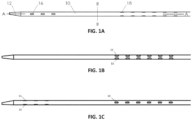
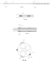
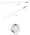
- FIGs. 1A, 1B, and 1C illustrate various views of a catheter 10 according to an exemplary embodiment.
- the catheter 10 is shown in a different rotational position around a longitudinal axis A-A through the catheter 10.
- the catheter 10 may include an elongated tubular member made of extruded polyurethane (or any other suitable biocompatible material).
- the catheter 10 may include a row of distal windows 16, which may be aligned along a longitudinal axis near a distal end 12 of the catheter 10.
- the catheter 10 may further include a second row of distal windows 16, which can be partially seen in FIG. 1C .
- the catheter 10 may similarly include two rows of proximal windows 18. These windows will be referred to herein as "proximal windows 18" to distinguish the proximal set of windows 18 from the distal set of windows 16.
- the catheter 10 may include three or more rows of distal windows 16 or three or more rows of proximal windows 18.
- the proximal windows 18 may have the same or different structural features as the distal windows 16.
- a section of the catheter 10 between the proximal windows 18 and the distal windows 16 may be free of windows.
- the catheter 10 includes six distal windows 16 and twelve proximal windows 18. However, in other embodiments, the catheter 10 may include fewer or more proximal or distal windows. For example, in other embodiments, the catheter 10 may include two, four, eight, ten, twelve, or more distal windows 16, and/or two, four, six, eight, ten, or more than twelve proximal windows 18.
- the distal windows 16 and proximal windows 18 may be configured in pairs such that the catheter 10 has an even number of distal windows 16 and an even number of proximal windows 18. However, the number of windows 16 or 18 may also be an odd number.
- the windows 16, 18 may be cut (e.g. by a laser, manual skive, drill, punch, etc.) through the exterior wall of catheter 10, or the windows may be formed by any other suitable method, such as during an extrusion process or other manufacturing process.
- the windows 16, 18 may be elongated along the longitudinal axis A-A. They may have a rectangular, oval, square, or any other shape.
- the windows 16, 18 may be apertures configured to allow electrical signals to travel from an interior lumen of the catheter 10 to the exterior of the catheter 10.
- the windows 16, 18 may be covered by a material that allows electrical signals to pass through.
- the proximal windows 18 may be rotationally offset from the distal windows 16.
- a straight line drawn proximally through a row of distal windows 16 does not pass through a row of proximal windows 18.
- one or more rows of proximal windows 18 may be aligned with a corresponding row of distal windows 16.
- catheter 10 may be customized in accordance with the anatomy of a particular patient.
- the length of the section of the catheter 10 that includes the proximal windows 18 may be 10cm or less, between 3-5cm, or between 1-3cm.
- the distance between two adjacent proximal windows 18 may be 5cm or less, 3cm or less, or may be around 1cm.
- the length of the section of the catheter 10 that includes the distal windows 16 may be 6cm or less, between 2-4cm, or between 1-2cm.
- the distance between two adjacent distal windows 16 may be 5cm or less, 3cm or less, or may be around 1cm.
- the length of the section of the catheter between proximal windows 18 and distal windows 16, which may be free of windows, may be 12cm or less, 10cm or less, or 8cm or less.
- the windows 16, 18 may have a length of 6mm or less, 5mm or less, 4mm or less, 3mm or less, 2mm or less, or 1mm or less. In one embodiment, the windows may have a length that is less than the length of corresponding electrodes that are electrically exposed through the windows. It should be understood that the above catheter dimensions are exemplary only, and the catheter 10 may have dimensions that vary from the above ranges and specific measurements.
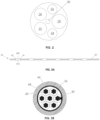
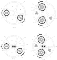
- FIG. 2 illustrates a cross-sectional view along plane II-II (see FIG. 1A ) of catheter 10.
- the interior of catheter 10 may include one or more lumens.
- the catheter 10 may include six lumens 20, 22, 24, 26, 28, 30, although the catheter 10 may include fewer or more lumens.
- the lumens 20, 22, 24, and 26 may be electrode assembly lumens used to receive electrode assemblies described in further detail below.
- proximal windows 18 may create a pathway between the interior of lumens 20, 22 and the exterior of catheter 10.
- lumens 20, 22 may receive electrodes that align with the proximal windows 18 shown in FIGs. 1A-1C .
- distal windows 16 may create a pathway between the interior of lumens 24, 26 and the exterior of catheter 10, and lumens 24, 26 may receive electrodes that align with the distal windows 16 shown in FIGs. 1A-1C .
- Lumens 20, 22 may therefore be proximal electrode assembly lumens, and lumens 24, 26 may be distal electrode assembly lumens.
- the proximal electrode assemblies placed in lumens 20, 22 may be used to stimulate a patient's left phrenic nerve
- the distal electrode assemblies placed in lumens 24, 26 may be used to stimulate a patient's right phrenic nerve.
- Lumen 28 may receive a guidewire
- lumen 30 may receive a steering mechanism, other instruments, wires, or may be used to transport fluid to or from a working site.
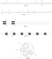
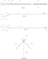
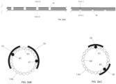
- FIG. 3A illustrates an exemplary embodiment of a proximal electrode assembly 32
- FIG. 3B illustrates a cross-sectional view of a single electrode 36 along plane IIIB-IIIB of FIG. 3A
- the proximal electrode assembly 32 may include six proximal electrodes 36
- FIG. 3C illustrates an exemplary embodiment of a distal electrode assembly 34
- FIG. 3D illustrates a cross-sectional view of a single electrode 38 along plate IIID-IIID of FIG. 3C
- the distal electrode assembly 34 may include three distal electrodes 38.
- the two electrode assemblies 32 and 34 may differ from one another in terms of number of electrodes, structural features of the electrodes, and structural features of the assembly as a whole.
- a proximal electrode assembly 32 may be held within one of proximal electrode assembly lumens 20, 22 of catheter 10, and a second proximal electrode assembly 32 may be held within the other of proximal electrode assembly lumens 20, 22 of catheter 10.
- distal electrode assembly 34 may be held within one of distal electrode assembly lumens 24, 26 of catheter 10, and a second distal electrode assembly 34 may be held within the other of distal electrode assembly lumens 24, 26 of catheter 10.
- This combination of two proximal electrode assemblies 32 and two distal electrode assemblies 34 within the lumens of catheter 10 may allow the twelve proximal electrodes 36 to align with the twelve proximal windows 18 and the six distal electrodes 38 to align with the six distal windows 16.
- FIGs. 3A and 3B will be referenced to describe proximal electrode assembly 32 in greater detail.
- Individual electrical leads 44 may be coiled together to form cable 40 of the proximal electrode assembly 32.
- Each lead 44 may include an elongated conductive member 45 and may be surrounded by a layer of non-conductive material 46.
- the lead 44 may be a wire
- the elongated conductive member 45 may include strands of stainless steel or another conductive material
- the non-conductive material 46 may be a layer of insulation.
- the leads 44 may deliver electrical or other signals to and from the electrodes 36.
- the cable 40 may include seven leads 44. Of these seven leads 44, six may be individually de-insulated at certain locations (e.g., underneath electrodes 36, as shown in FIG. 3B ) to expose the conductive member 45 underneath.
- a conductive connector 42 which may be thin, flexible, and made of stainless steel or another conductive material, may be joined (e.g. mechanically, adhesive, micro-welded, etc.) to the exposed conductive member 45 and wrapped transversely around the cable 40.
- the conductive connector 42 may provide a contact surface between the exposed conductive member 45 and an electrode 36.
- the electrode 36 may be a platinum-10% iridium (or any other suitable implantable electrode material like stainless steel, platinum, titanium nitride, coated stainless steel, etc.) ring electrode, which is crimped (or adhered, microwelded) to the exterior of the conductive connector 42 and cable 40.
- the seventh insulated lead 44 shown in the center of FIG. 3B may help support and stiffen the cable 40.
- the seventh lead 44 also may be used to carry other types of signals, for example signals from a sensor or ECG signals. In total, as noted above, two seven-lead proximal electrode assemblies may be inserted into the lumens 20, 22 of catheter 10.
- cable 48 of a distal electrode assembly 34 may include three electrical leads 44, which may be constructed in a similar manner as described in connection with the proximal electrode assembly 32.
- Three electrodes 38 may be mounted to conductive connectors 42, which are connected to exposed conductive members 45 of corresponding leads 44.
- partial or semi-circular electrodes may be used instead of ring electrodes 36, 38.
- the number of lumens within catheter 10, number of cables 40, 48, the number of electrodes 36, 38 on each cable 40, 48, respectively, and the distance between electrodes 36, 38, along with other structural features, may be varied to fit particular applications.
- any of the proximal electrodes 36 or the distal electrodes 38 may be used to measure electrical signals or other data from within the patient's body.
- the electrodes may serve as sensors that receive electrical or other types of information from the patient.
- FIGs. 4A-4D illustrate how multiple electrode assemblies 32, 34 may be within the lumens of catheter 10.
- a catheter 10 is depicted in FIG. 4A
- two proximal electrode assemblies 32 are depicted in FIG. 4B
- two distal electrode assemblies 34 are depicted in FIG. 4C .
- the two proximal electrode assemblies 32 may be placed within lumens 20, 22 of catheter 10 such that the electrodes 36 align with proximal windows 18.
- the two distal electrode assemblies 34 may be placed within lumens 24, 26 of catheter 10 such that the electrodes 38 align with distal windows 16 (not shown in FIG. 4A ).
- the electrode assemblies 32, 34 may be fixed (e.g. with adhesive or by any other structure or method) within their respective catheter lumens.
- FIG. 4D illustrates a cross-section of catheter 10, taken along plane IVD-IVD of FIG. 4A , that shows the catheter with two proximal electrode assemblies 32 and two distal electrode assemblies 34 within lumens 20, 22, 24, 26 of catheter 10.
- a medical device 50 may include a catheter 10 having two proximal electrode assemblies 32 and two distal electrode assemblies 34.
- the electrode assemblies 32, 34 may be within the elongated tubular member of catheter 10 such that electrodes 36 are exposed through proximal windows 18 and electrodes 38 are exposed through distal windows 16.
- the cables 40, 48 formed of electrical leads 44 may exit through the proximal end of the catheter 10 and may be attached (e.g. by solder, crimp, PCB, etc.) to connectors 52, 54.
- the electrode assemblies 32, 34 which may include leads 44 and electrodes 36, 38, may be introduced into one or more lumens through lumen openings at either the proximal end or distal end of catheter 10.
- the leads 44 may be inserted into a proximal end of the catheter 10 and threaded or pulled through one or more lumens until electrodes 36, 38 are located at predetermined locations in a more distal portion of the catheter 10.
- Portions of the catheter wall may be removed, either before or after insertion of the electrode assemblies 32, 34, to create windows 18, 16. Windows 18, 16 may expose the electrodes, allowing for a conductive path between the electrodes 36, 38 and the blood vessel lumen in which the medical device 50 may be placed.
- the medical device 50 may be used for transvascular stimulation of nerves in the neck and/or chest of a human or other mammal (e.g., a pig, a chimpanzee).
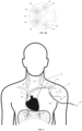
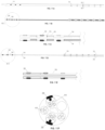
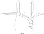
- FIG. 5 illustrates the anatomy of selected nerves and blood vessels in the neck and chest of a human and, in particular, the relative locations of the left phrenic nerve (PhN) 56, right phrenic nerve 58, vagus nerves (VN) (not shown), external or internal jugular veins (JV) 60, brachiocephalic veins (BCV) 62, superior vena cava (SVC) 64, and left subclavian vein (LSV) 66.
- PhN left phrenic nerve
- VN vagus nerves
- JV external or internal jugular veins
- BCV brachiocephalic veins
- SVC superior vena cava
- LSV left subclavian vein
- the medical device 50 may be used to rhythmically activate the diaphragm by inserting the catheter 10, with one or more electrode assemblies 32, 34, percutaneously into central veins of a patient.
- Percutaneous insertion of the catheter 10 may be accomplished by the Seldinger technique, in which a guide wire is inserted through a hypodermic needle into a vein. The distal tip of the catheter is then passed over the guide wire and advanced into the vein.
- the shape and mechanical properties of the catheter may be designed to urge the catheter 10 to gently hug the vein wall in regions adjacent to the right and left phrenic nerves, as shown in FIG. 5 .
- the medical device 50 may be inserted into the left subclavian vein 66 and advanced into the superior vena cava 64. In another configuration, not shown, the medical device 50 may be inserted into the left jugular vein and advanced into the superior vena cava 64.
- the catheter 10 may be inserted in a minimally-invasive way and may be temporarily placed into, and thus removable from, the patient.
- the windows 18 are oriented such that, when the catheter is inserted into the left subclavian vein 66, the six pairs of windows 18 are directed posteriorly towards the left phrenic nerve 56 and the three pairs of distal windows 16 are directed laterally towards the right phrenic nerve 58.
- the electrode assemblies 34 may include electrodes 38 arranged and oriented to most effectively stimulate a nerve extending parallel to the catheter 10 (e.g., the right phrenic nerve 58 in FIG. 5 ), and the electrode assemblies 32 may include electrodes 36 arranged and oriented to most effectively stimulate a nerve extending at transverse or right angles to the catheter 10 (e.g., the left phrenic nerve 56 in FIG. 5 ).
- the electrode assemblies 34 may include electrodes 38 arranged and oriented to most effectively stimulate a nerve extending at transverse or right angles to the catheter 10, and the electrode assemblies 32 may include electrodes arranged and oriented to most effectively stimulate a nerve extending parallel to the catheter 10.
- the electrodes 38 of the electrode assemblies 34 have been placed in a more distal location along catheter 10 than the electrodes 36 of electrode assemblies 32.
- the electrode assemblies 32 may be arranged within the catheter 10 such that their electrodes 36 are more distal than the electrodes 38 of the electrode assemblies 34.
- the windows 16, 18 of the catheter 10 may be configured to accommodate the alternative placement of the electrode assemblies 32, 34.
- testing may be done to locate the right phrenic nerve 58 and to determine which pair of electrodes 38 (out of the distal set of electrodes 38) most effectively stimulate the right phrenic nerve 58.
- testing may be done to locate the left phrenic nerve 56 and to determine which pair of electrodes 36 (out of the proximal set of electrodes 36) most effectively stimulate the left phrenic nerve 56.
- testing could involve the use of a signal generator to systematically send electrical impulses to selected electrodes. By observing the patient's condition or by using sensors, the ideal electrode pairs may be identified.
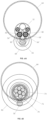
- FIG. 6A illustrates a cross-sectional view of catheter 10 along the plane VIA-VIA shown in FIG. 4A and will be referenced to describe selective activation of a pair of electrodes for stimulating a nerve.
- the electrodes of FIG. 6A may be any electrode pair located at any location along catheter 10, and the nerve 56 may be any nerve located parallel, transverse, or at any other orientation with respect to catheter 10.
- proximal electrodes 36 and left phrenic nerve 56 are referenced in connection with FIG. 6A , even though left phrenic nerve 56 is shown transverse to catheter 10 in FIG. 5 .
- a pair of distal electrodes 38 also may be selectively activated to stimulate the right phrenic nerve 58.
- an electrical potential may be created between a pair of selected bipolar electrodes, such as between a first electrode 36' and a second electrode 36".
- the first electrode 36' may be aligned with a first window 18'
- the second electrode 36" may be aligned with a second window 18".
- the arrangement of the first and second electrodes 36', 36" and the first and second windows 18', 18” may create an electrical field 68 in the vicinity of first and second windows 18', 18".
- the first and second electrodes 36', 36" may be selected to effectively target a nerve, such as the left phrenic nerve 56 shown in FIG. 6A or another nerve near the electrodes 36', 36".
- the windows 18', 18" and the resulting electrical field 68 may therefore be oriented towards the left phrenic nerve 56 or other target nerve.
- the catheter 10 with windows 16', 16" therefore acts as an insulative barrier that constrains and focuses the electrical field 68, rather than allowing the electrical field 68 to expand radially outwards in all directions.
- the focused electrical field allows target nerve stimulation at lower energy levels and avoids stimulating unwanted nerves or other structures.
- the stimulation current may be between 10 - 6000nC (nanocoulombs) or between 50-500nC.
- FIG. 6B illustrates an exemplary prior art nerve stimulation device 70 that may be used to stimulate a nerve 78.
- the prior art device 70 may include lead wires 72 and an electrode 74.
- the device 70 may be inserted into a blood vessel 76, and an electrical field 80 may be created around the device 70.
- the electrical field 80 may be created around the circumference of the device 70.
- the electrical field is not confined to a specific location and therefore may also target other anatomical structures within the patient.
- the windows 16, 18 of catheter 10 may allow the use of lower and safer electrical currents to activate the phrenic nerves 56, 58 and prevent overstimulation or unwanted activation of nearby structures such as other nerves, muscles, or the heart.
- FIGs. 7A-13K illustrate additional or alternative embodiments of electrodes and electrode assemblies that may be used with any of the catheters described herein.
- the below embodiments may be variations of the electrode assemblies and electrodes described previously. Therefore, features not mentioned may be unchanged or logical modifications of the above-described embodiments.
- proximal electrodes 36, proximal electrode assemblies 32, distal electrodes 38, and distal electrode assemblies 34 of each embodiment will be referred to using the same reference numerals as used above, even though some features of these components may be modified in the below embodiments.
- the layer of non-conductive material 46 may be removed from portions of leads 44 to expose the underlying conductive member 45.
- FIG. 7A illustrates a catheter 10
- FIG. 7B illustrates a proximal electrode assembly 32.
- the exposed conductive members 45 (straight or coiled for increased surface area) of leads 44 may be positioned within windows 16 or 18 of the catheter 10 and, in some embodiments, may extend radially out of the windows 16, 18.
- the conductive member 45 may pass out of a lumen of the catheter 10 through an aperture in the catheter outer wall, travel in a proximal-distal direction, and then pass back through another aperture in the outer wall of catheter 10.
- the portion of the conductive member 45 that forms an electrode 36, 38 may be the distal end of a lead 44.
- the insulated leads 44 may additionally or alternatively be sewn into the catheter 10, leaving the exposed conductive member 45 on the exterior of the catheter 10 and the remaining insulated lead 44 inside a catheter lumen.
- FIG. 7D illustrates a cross-section of catheter 10 through a pair of proximal electrodes 36 that include exposed conductive members 45.
- a conductive member such as an electrode described in connection with FIGs. 10A-10E
- a conductive member may be fixed (e.g., with adhesive, heat fusion, etc.) to the exterior of catheter 10 and in electrical contact (e.g., mechanically, microwelded) with the exposed conductive member 45. Fixing such a conductive member to the exposed conductive member 45 may increase certain electrical properties of the electrode, such as conductivity and surface area, relative to an electrode that only includes the exposed conductive member 45.
- Examples of conductive member material include platinum, platinum iridium, gold, stainless steel, titanium nitride, MP35N, palladium, etc.
- FIG. 8A illustrates a catheter having electrodes and leads that are printed directly onto the exterior of catheter 10.
- FIG. 8B illustrates an exploded view of distal electrodes 38 of the catheter 10
- FIG. 8C illustrates an exploded view of proximal electrodes 36 of catheter 10
- FIG. 8D illustrates a transverse cross-sectional view of a proximal electrode pair 36 taken along plane VIIID-VIIID of FIG. 8C .
- Electrodes 36, 38 may be formed by conductive inks (such as silver flakes or carbon flakes suspended in polymer). These conductive inks may be deposited and adhered directly onto the catheter 10 and sealed, except for the exposed electrodes 36, 38, with an outer polyurethane or other flexible insulative film.
- the exposed electrodes 36, 38 also may be coated (e.g., with titanium nitride) for purposes such as one or more of: enhancing electrical properties, such as conductivity and surface area; providing corrosion resistance; and reducing the potential for formation of silver oxide which could be toxic.
- the conductive ink trace of distal electrodes 38 may travel proximally along catheter 10 past the proximal electrodes 36.
- the use of printed electrodes may reduce the overall complexity of the design while maximizing the useable catheter lumen space, without changing the catheter profile or flexibility too drastically.
- the profile of the catheter may be reduced because of the space saved by using electrodes printed on the exterior of the catheter.
- one or several catheter lumens may be used for fluid delivery, blood sampling, or central venous pressure monitoring.
- several of the catheter lumens, such as lumens 20, 22, 24, 26 may be eliminated since there are no catheter assemblies as described in connection with other embodiments.
- the catheter 10 may include only lumen 28 and lumen 30. If the catheter 10 with printed electrodes includes fewer than the six lumens shown in FIG. 2 , for example, its cross-sectional area may be reduced, one or more of the fewer lumens may be made larger to accommodate larger tools or other objects, or one or more smaller lumens may be added to accommodate tools or other objects.
- FIGs. 9A-9E illustrate electrodes 36, 38 supported by catheters 94, 96 that may be placed within a lumen of catheter 10.
- proximal electrodes 36 may be joined by an electrode catheter 94
- distal electrodes 38 may be joined by an electrode catheter 96.
- the catheters 94, 96 may be elongated tubular members that include a non-conductive material.
- the electrodes 36, 38 may be crimped onto the catheters 94, 96 and may be electrically connected to conductive members 45 of leads 44 through the walls of the electrode catheters 94, 96.
- the catheters 94, 96 may have cross-sectional areas that are smaller than the cross-sectional areas of their respective lumens of catheter 10 so that catheters 94, 96 may be inserted into the lumens of catheter 10.
- the electrodes 36, 38 may be aligned with windows 18, 16 of catheter 10 and fixed in place, similar to other embodiments.
- leads 44 may travel in a proximal-distal direction through the electrode catheters 94, 96.
- one or more catheters having a single electrode 36 or 38, or a pair of bipolar electrodes may be inserted into a lumen of catheter 10 during a procedure (i.e., while catheter 10 is within a patient's vascular system) and advanced to various windows 18, 16 until optimal locations are found. By doing so, less material may be used, which may drive down the cost of production of the medical device 50.
- FIGs. 10A-10E illustrate electrodes 36, 38 on the exterior of a catheter 10.
- electrodes 36, 38 may be connected (microwelded, etc.) to a lead 44 and may be fixed (e.g., crimped, adhered, etc.) onto the exterior of catheter 10.
- the lead 44 may be inserted through the wall of the catheter 10 (e.g., through a window 16, 18) and into a lumen within the catheter 10.
- one or more ring electrodes may be fixed to the exterior of the catheter 10.
- an insulative coating may be applied to cover a portion of the electrodes.
- FIGs. 11A-11F illustrate an embodiment in which the manufacturing process of electrode assemblies 32, 34 may include injection molding.
- electrodes 36, 38 may be individually attached to leads 44 by injection molding, with the electrodes 36, 38 in electrical contact with conductive members 45.
- the molding process may form a covering 98 around each lead 44.
- the covering 98 may include a non-conductive material, such as plastic.
- the electrodes 36, 38 may be flat, semi-circular, or any other suitable shape.
- the covering 98 may form any shape around the leads 44, such as the shape shown in FIG. 11F .
- the electrodes 36, 38 and bundle of leads 44 may be placed within an injection molding jig that injects material, such as plastic, around the bundle of leads 44 to anchor the electrodes in place, forming a covering 98 but in one embodiment leaving at least a portion of the electrodes 38 exposed.
- the electrodes may be covered by a thin layer of polymer, which may be removed in a subsequent step.
- the covering 98 may be placed in the longitudinal vicinity of the electrodes and might only surround a single lead, and thus may be referred to as "partial.”
- FIG. 11C the covering 98 may be placed in the longitudinal vicinity of the electrodes and might only surround a single lead, and thus may be referred to as "partial."
- the covering 98 may cover a larger longitudinal portion of the underlying leads 44 and may surround multiple leads, and thus may be referred to as "full.”
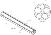
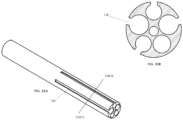
- FIGs. 12A-12K illustrate yet another embodiment of electrode assemblies 32, 34.
- tubular members 100 may support the distal ends 102 of leads 44 and hold the distal ends 102 adjacent to electrodes 36, 38.
- FIG. 12A illustrates a catheter 10
- FIG. 12B illustrates a perspective view of a distal electrode assembly 34
- FIG. 12C illustrates a perspective view of a proximal electrode assembly 32
- FIG. 12D illustrates a side view of the distal electrode assembly 34 of FIG. 12B
- FIG. 12E illustrates a side view of the proximal electrode assembly 32 of FIG. 12C
- FIG. 12F illustrates a transverse cross-sectional view of a distal electrode 38 of FIG. 12D
- FIG. 12G illustrates a transverse cross-sectional view of a proximal electrode 36 of FIG. 12E
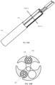
- 12H illustrates a transverse cross-sectional view of the catheter of FIG. 12A with two distal electrode assemblies 34 of FIG.
- FIG. 12I illustrates a transverse cross-sectional view of the catheter 10 of FIG. 12A with two proximal electrode assemblies 32 of FIG. 12C within the catheter lumens;
- FIG. 12J illustrates the view of FIG. 12H with ECG wires through a central lumen of the catheter 10; and
- FIG. 12K illustrates the view of FIG. 12I with ECG wires through a central lumen of catheter 10.
- FIGs. 12B-12G illustrate the proximal and distal electrodes 36, 38 of the proximal and distal electrode assemblies 32, 34, respectively.
- electrode assemblies 32, 34 include leads 44, similar to other embodiments.
- the distal portions 102 of leads 44 may include exposed conductive members 45 and may be attached by welding or any other method to the exterior of a tubular member 100 and to the interior of electrodes 36, 38.
- the tubular member 100 may be 1-6mm in length, 2-4mm in length, and in one embodiment about 3mm in length, although the tubular member 100 may be any other suitable length.
- the tubular member 100 may be a stainless steel hypodermic tube. (In FIGs.
- tubular members 100 are not shown and would be all or mostly covered by electrodes 36, 38.
- Distal portions 102 of leads 44 are labeled in FIGs. 12D and 12E to show their general location, although they are underneath electrodes 36, 38.) As can also be seen in FIGs. 12F and 12G , the distal portions 102 of leads 44 may cause the electrodes 36, 38 to protrude radially outward.
- Each lead 44 may travel proximally through any electrodes 38, 36 that are positioned more proximally than the electrode to which the distal end 102 of that lead is attached.
- the lead 44 that is attached to the most distal electrode 38 of the distal electrode assembly 34 may travel proximally through the other two electrodes 38 and through all six proximal electrodes 36.
- the lead 44 attached to the most distal electrode 36 may travel proximally through each of the other five electrodes 36.
- the distal electrode assembly 34 may include three leads 44 - one for each electrode 38.
- the proximal electrode assembly 32 may include six leads 44 - one for each electrode 36.
- the leads may be coiled to form cables 48, 40.
- cable 48 formed of leads 44 from distal electrode assembly 34
- cable 48 may include one or two leads.
- cable 40 formed of leads from proximal electrode assembly 32
- cable 40 may include one, two, three, four, or five leads.
- cable 40 may include six leads 44.
- FIGs. 12H and 12I illustrate cross-sectional views with the electrode assemblies 34, 32 within lumens of the catheter 10.
- the catheter 10 may still include lumens 20, 22 configured to receive proximal electrode assemblies 32, lumens 24, 26 configured to receive distal electrode assemblies 34, a lumen 28 configured to receive a guidewire, and a lumen 30 configured to receive a steering mechanism or other structures.
- distal electrodes 38 may be aligned with distal windows 16.
- FIG. 12I illustrates proximal electrodes 36 aligned with proximal windows 18.
- the leads 44 from distal electrode assemblies 34 can be seen in the cross-sectional view of FIG. 12I because the leads 44 may travel proximally through lumens 24, 26.
- FIGs. 12J and 12K are similar to the views shown in FIGs. 12H and 12I , except FIGs. 12J and 12K illustrate two electrocardiography (ECG) conductive members 104 within lumen 30.
- ECG conductive members 104 may be coupled to one or more ECG electrodes 106 (see FIG. 12A and FIG. 14 ) located at a distal end of catheter 10, for sensing ECG signals of a patient.
- each electrode 36, 38 may be movable with respect to other electrodes 36, 38.
- the electrodes 36, 38 are connected by leads 44, the leads 44 typically are flexible. Therefore, when placing electrode assemblies 32, 34 within catheter 10 during manufacture of the medical device 50, this embodiment allows each electrode 36, 38 to be positioned within its respective window 18, 16 at least partially independently of other electrodes. Independent positioning of the electrodes may allow positioning errors to be minimized, as opposed to embodiments in which electrodes 36, 38 are fixed to other electrodes by a catheter or other rigid structure.
- FIGs. 13A-13K illustrate an embodiment that is similar to the embodiment shown in FIGs. 12A-12K . Similar features from the embodiment of FIGs. 12A-12K will not be repeated here.
- the main difference between the embodiment of FIGs. 13A-13K and the embodiment of FIGs. 12A-12K is that each of the electrodes 36, 38 of FIGs. 13A-13K may form an arcuate shape that functions to hold and contact the distal ends 102 (including exposed conductive members 45) of leads 44.
- the proximal and distal assemblies 32, 34 of FIGs. 13A-13K may or may not include tubular members 100.
- each of the electrodes 36, 38 may be C-shaped and may have an outer wall 108 and an inner wall 110.
- the outer wall 108 and the inner wall 110 of an electrode may sandwich the exposed conductive member 45 at the distal end 102 of a lead 44.
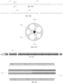
- FIG. 14 illustrates two ECG electrodes 106 and their associated components. As with all other features in this application, the ECG electrodes 106 may be used with any of the other embodiments described herein.
- the ECG electrodes 106 may be located at a distal end of a catheter 10 (see FIG. 12A ).
- the catheter 10 may include two ECG electrodes 106, although in some embodiments the catheter 10 may include one electrode 106 or more than two electrodes 106.
- a conductive member 104 which may be insulated, may connect each electrode 106 to an ECG system located outside of the patient.
- the ECG conductive members 104 may be braided or twisted together and may be surrounded by a non-conductive layer 105 (also shown in FIGs. 12J and 12K ).
- the electrodes 106 may monitor a patient's heart rate.
- Heart rate monitoring may be beneficial during use of medical device 50 to alert a medical practitioner to changes in the patient's heart rate. Changes in the patient's heart rate may be caused by the medical device 50 stimulating certain nerves or by unintentional stimulation of the patient's heart. Heart rate monitoring also may be relied on to achieve steady recruitment of a nerve. For example, the catheter 10 may move when a patient's heart beats, causing fluctuations in nerve stimulation. If the patient's heart rate is known, the electrical potential created between a pair of bipolar nerve-stimulating electrodes can be adjusted in real time to deliver a constant charge to the nerve.
- a variety of steering mechanism may be included in a medical device 50 to help control positioning of catheter windows 16, 18, and thus electrodes 38, 36, within a blood vessel.
- a steering mechanism may be located within a central lumen 30 of catheter 10 or within other lumens of the catheter 10. It may be beneficial to position at least some electrodes 36, 38 in close proximity to each target nerve, as having electrodes situated close to the nerve can reduce the amount of current shunted through the blood and thus may reduce the electrical current needed to activate the nerve.
- proximal windows 18 may help position the proximal windows 18 in a desired location within a blood vessel.
- the typical subclavian vein penetration angle and the shape and elasticity of catheter 10 may combine to position the proximal windows 18 along a posterior wall of the subclavian vein, in close proximity to the left phrenic nerve, which normally descends dorsal to the left subclavian vein.
- the medical device 50 may include stiffening elements and steering mechanisms.
- the stiffening elements and steering mechanisms may help position the distal set of electrodes 38 against a lateral wall of the superior vena cava, close to the right phrenic nerve.
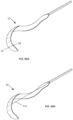
- a steering mechanism 112 may include a single pre-shaped elongated member 114, such as a wire or tube (i.e. stainless steel, nitinol, hypodermic tube, etc.) to steer the catheter 10.
- the elongated member 114 may include a handle 120, a proximal portion 116 coupled to the handle 120, and a distal portion 118 that is bent with respect to the proximal portion 116.
- the distal portion 118 may correspondingly turn into a variety of positions and may function to position the distal end of catheter 10.
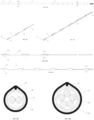
- FIGs. 15A-15C illustrate the elongated member 114 in three different positions: a first position indicated by distal portion 118a, a second position indicated by distal portion 118b, and a third position indicated by distal portion 118c.
- FIG. 15A illustrates a front view of the steering mechanism 112 in three different positions
- FIG. 15B illustrates a top view of steering mechanism 112 in three different positions
- FIG. 15C illustrates a view from the distal end of the steering mechanism 112 to the proximal end of the steering mechanism 112 when the steering mechanism 112 is in three different positions.
- Elongated member 114 may be stiff enough to ensure that the distal portion of the catheter 10, which includes the distal electrodes 38, is placed against the vessel wall.
- the elongated member 114 also may be stiff enough to transmit steering torque from the proximal handle 120 to the distal portion 118.
- another embodiment of steering mechanism 112 may include one or more control members 122.
- the control members 122 may be pulled or pushed to bend or deflect a portion of catheter 10.
- the control members 122 may be surrounded by and may slide longitudinally relative to one or more tubular members 124, such as hypodermic tubes or compression coils.
- the tubular members 124 may be flexible.
- the steering mechanism 112 of this embodiment may further include a stiffening element 126, such as a tube or rod, which may be attached (e.g., by weld, adhesive, etc.) to the tubular members 124.
- FIGs. 16A-16E may allow bidirectional steering of catheter 10.
- a handle (not shown) may facilitate pulling or pushing of the control members 122 relative to their corresponding tubular members 124.
- the distal end of the steering assembly 112 may include gaps 128 between tubular members 124. The gaps 128 may facilitate bending of the distal end of the catheter 10.
- the steering mechanism 112 may be adhered within the central lumen 30 or another lumen of the catheter 10.
- tubular members 124 may include narrowed portions 130.
- the narrowed portions 130 may replace the gaps 128 or may be used in combination with gaps 128 to provide the desired flexibility.
- the narrowed portions 130 may be formed using a laser or by any other method.
- control members 122 may be located in separate lumens 132, 134 within catheter 10. Similar to the embodiment of FIGs. 16A-16E , the control members 122 may be surrounded by one or more tubular members 124, which may be hypodermic tubes or compression coils. In one embodiment, each tubular member 124 does not surround a distal end portion of its respective control member 122. The distal end portion of the control member 122 may therefore be fixed to the distal end of its corresponding lumen 132, 134. A distal end portion of each tubular member 124 also may be fixed to its respective lumen 132, 134 at a position more proximal than the fixed portion of the control member 122.
- a gap extending longitudinally along the lumen may be left between the fixed portion of the control member 122 and the fixed portion of its corresponding tubular member 124 such that, when the control member 122 is pulled or pushed relative to its tubular member 124, deflection of the catheter 10 occurs within the gapped space.
- steering mechanism 112 may include a single control member 122.
- the control member 122 may be surrounded by a tubular member 124 and may be pushed or pulled relative to the tubular member 124 to deflect the distal end of catheter 10.
- a distal portion of the control member 122 may be fixed within the distal end of lumen 30, or another lumen of catheter 10, and the tubular member 124 may be fixed to a more proximal location within lumen 30.
- a gap may be formed between the fixed portion of control member 122 and the fixed portion of tubular member 124 to control the deflection locations of the catheter 10.
- the control member 122 may be pulled to deflect the catheter tip in one direction and pushed to deflect the catheter tip in the other, opposite direction.
- any of the steering mechanisms described above may include a balloon, which may be inflated to assist in urging the distal portion of the catheter 10 and the distal electrodes 38 against the superior vena cava lateral wall.
- the balloon may be attached to a side of the catheter opposite the windows corresponding to distal electrodes 38. Upon inflation of the balloon, electrodes 38 may be urged towards a wall of the superior vena cava.
- the windows 16, 18 of catheter 10 may have a variety of alternative configurations.
- windows 16 may be offset from other windows 16, and windows 18 may be offset from other windows 18 with respect to a proximal-distal line 136 on the exterior surface of catheter 10 or with respect to a circumferential line 138 around the circumference of catheter 10.
- windows 16 may be offset from each other if the more proximal window 16 does not lie on the same proximal-distal line 136 drawn through the center of the most distal window 16.
- Each window 18 of FIGs. 20B and 20C may be offset from other windows 18 with respect to circumferential lines 138 drawn through the center of windows 18.
- Embodiments of catheter 10 include windows 16, 18 with any configuration of offset and non-offset windows.
- the set of windows 16 or rows of windows 16 may be offset from the set of windows 18 or rows of windows 18 with respect to a proximal-distal line 136.
- electrode configuration relative to the nerve may reduce the amount of electrical current required to stimulate nerve axons.
- Nerve axons may require lower activation currents when the electrodes and the direction of current flow are parallel to or along the nerve, thus producing a longitudinal transmembrane depolarization of sufficient magnitude to initiate action potentials.
- the direction the nerve courses is not exactly known and can vary from one individual to another.
- Electrodes 36 may be arranged in a straight line (e.g., along circumferential line 138 as in FIG. 20A ), staggered (e.g., FIG. 20B ), or angled (e.g., FIG. 20c ) along a circumference of the catheter 10 to ensure that the nerves may be effectively stimulated.
- a straight line e.g., along circumferential line 138 as in FIG. 20A
- staggered e.g., FIG. 20B
- FIG. 20c angled along a circumference of the catheter 10 to ensure that the nerves may be effectively stimulated.
- the circumferential line 138 may pass through (or over) the center of two electrodes, or the circumferential line 138 may pass through (or over) other portions of the two electrodes (e.g., the pair of electrodes may be slightly offset).
- staggered electrode pairs may be arranged such that the longitudinal distance (along a proximal-distal line parallel to the longitudinal axis of catheter 10) between longitudinally adjacent electrodes (such as between electrodes 18a and 18b), is approximately equal to the longitudinal distances between other pairs of longitudinally adjacent electrodes, such as 18b and 18c.
- angled pairs of electrodes may be arranged such that planes passing through the center of the pairs of electrodes do not form a right angle with respect to the longitudinal axis of the catheter 10.
- the staggered electrode embodiment of FIG. 20B is a subset of the angled electrode embodiment of FIG. 20C
- the embodiment of FIG. 20A in which a circumferential line 138 passes through or over non-center portions of electrode pairs also may be considered to include angled electrode pairs.
- the electrode configuration may be varied along the catheter 10 to account for the anatomical differences found among different patients. Selecting appropriate electrode pairs can provide effective nerve stimulation despite these differences.
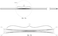
- FIG. 21 illustrates a medical device 50 having a pre-shaped catheter 10, with electrodes 36, 38 according to any embodiments disclosed herein.
- the pre-shaped catheter 10 may have arcuate, coiled, s-shaped, u-shaped, or any other pre-shaped portions.
- the pre-shaped catheter 10 may help ensure that the electrodes 36, 38 are in close contact with the vessel wall and thus closer to the phrenic nerve or other nerves, even in individuals where the right phrenic nerve may course more anteriorly or posteriorly than normal.
- the pre-shaping of the catheter 10 may be accomplished, for example, by a stiffening element inserted within the catheter lumens, or pre-shaped during the manufacturing process.
- the pre-shaped catheter 10 may be flexible but may have some stiffness and may tend to return to its pre-shaped configuration. When inserted over a stiffer guidewire, the catheter 10 may straighten for the ease of insertion. When the guidewire is taken out, the catheter 10 may return to its pre-shaped form.
- the catheter 10 may include elongated openings 140 along the its exterior.
- the elongated openings 140 may connect the exterior of the catheter 10 to an interior lumen and may be referred to as slits or channels.
- the elongated openings 140 may extend along the full length of the catheter 10.
- the elongated openings 140 may extend along part of the length of the catheter 10.
- the elongated openings 140 may additionally or alternatively be covered by a sleeve 142.
- Threading electrode assemblies 32, 34 through the lumens of catheter 10 during assembly of medical device 50 may present challenges due to the length of the lumens and their small diameter.
- the electrode assemblies 32, 34 may be inserted into one or more lumens of catheter 10 through elongated openings 140.
- the ability to access the lumens of the catheter 10 from locations radially outside of the lumens, rather than from the proximal and distal ends of the lumens, may simplify installation of electrical leads 44 and other components of the medical device 50 during the manufacturing process.
- the elongated openings 140 may be created during an initial extrusion or molding process to form catheter 10 or may be created during a later step.
- suitable polymers for the first extrusion or molding are: low and high-density thermoplastic polyurethanes such as polyester, polyether, and polycarbonate-based varieties; polycarbonate-based polyurethanes; and polyamides (nylon) and polyamide block copolymers (PEBA).
- an outer sleeve142 may be threaded over the catheter 10 to secure the wire assemblies within the lumens.
- the outer sleeve 142 may be a polymeric tubular sleeve and may be formed by extrusion.
- the inner diameter of the outer sleeve 142 may be large enough to slide over the outside of the catheter 10 but may be small enough to retain the electrode assemblies 32, 34 within the lumens of the catheter 10 after it has been slid over the catheter 10.
- the outer sleeve 142 may extend in a proximal-distal direction along a desired length of the catheter 10.
- the outer sleeve 142 may be formed of a thin, thermoplastic material such as, but not limited to, polyamide, polyether block amide, polyurethane, silicone rubber, nylon, polyethylene, fluorinated hydrocarbon polymers, etc. Examples of polymer materials suitable for use in the sleeve are commercially available under the trademarks PEBAX TM and PELLETHANE TM .
- the outer sleeve 142 may be thermally bonded or otherwise mechanically attached to the catheter 10 by any of a number of methods.
- a tubular member which may be formed by extrusion, may be placed over and around both the catheter 10 and the outer sleeve 142.
- the tubular member may be shrinkable to compress against the outer sleeve 142.
- the tubular member may comprise heat shrink tubing.
- the heat shrink tubing can be formed of one or more layers depending upon the desired properties. As an example, heat-shrink tubing from Parker TexLoc (Fort Worth, TX) has two layers for electrical insulation.
- Texflour fluoropolymer double-shrink heat shrinkable tubing has an outer layer of PTFE heat shrink with an inner layer of FEP tubing.
- the catheter 10 may be encapsulated by the FEP tubing as the PTFE shrinks, melting the FEP and creating a waterproof protective covering which is desirable for a variety of applications including RF and electrical stimulation devices.
- Thermal energy then may be applied to the heat shrink tubing to compress the heat shrink tubing around the outer sleeve 142 and the catheter 10. Contraction of the heat shrink tubing provides a compressive force directed radially inward on the outer sleeve 142. The compressive force exerted by the heat shrink tubing helps secure the outer sleeve 142 to the catheter 10.
- thermal energy e.g. RF heating, electromagnetic induction heating, etc.
- the thermal energy may be sufficient to elevate the temperature of the assembly in order to induce bonding of the outer sleeve 142 to the catheter 10.
- the combination of the compressive force generated by the heat shrink tubing and the thermal energy heating the materials above their respective melt temperatures will serve to bond the outer sleeve 142 and the catheter 10 together.
- the thermal energy is typically not high enough to create a bond between the heat shrink tubing and the polymeric sleeve nor is it high enough to damage the integrity of the catheter assembly.
- the heat shrink tubing may then be removed from the assembly comprising the catheter 10 (which is received inside the outer sleeve 142).
- a slit, notch, perforations, or other weakened regions may be used to assist with the removal of the heat shrink tubing from the assembly.
- the shrink tubing may be constructed of a biocompatible material such as EPTFE and can be left on the catheter assembly.
- a support structure such as a polytetrafluoroethylene (e.g., Teflon) coated mandrel, which may provide interior support to maintain the structure of the catheter 10 and preserve the patency of the longitudinal lumen throughout the manufacturing process.
- the support structure can later be removed by pulling it through either the distal or proximal openings in the lumen. In some cases the support structure can be stretched and elongated, thereby reducing its cross-sectional area, prior to removal.
- One or more outer sleeves 142 of different materials, thicknesses, or material properties can be used at various locations along the length of catheter 10 to alter various physical properties (e.g. stiffness, torqueability, friction, etc.) at specific locations along the length of the finished catheter.
- a flexible sleeve 142 could be utilized at the distal portion of the catheter 10 to allow the tip of the catheter 10 to more easily track along a guidewire.
- a more rigid sleeve 142 could be used at the proximal portion of the catheter 10 to allow for more pushability or torqueability when grasping the distal end of the catheter 10.
- Adjacent sleeves142 could be butt-welded or otherwise coupled end-to-end during the final forming process. Lap-joints or scarf joints may optionally be used to form a smoother transition between adjacent sleeves 142.
- a shaping element may be inserted into one of the elongated openings 140, or into an enclosed lumen, at a desired location along the first extrusion.
- the shaping element may be formable or pre-formed to impart a desired configuration (e.g. a desired curvature) to the catheter 10.
- the shaping element may be pre-formed or formed to cause the catheter 10 to curve in a plane having a desired angular relationship, such as, for example, to aid in positioning electrodes 36, 38 of the medical device 50.
- the shaping element may be resiliently flexible.
- the shaping element may comprise a predetermined length of e.g. nitinol wire, ribbon, spring, etc.
- the shaping element may comprise a temperature-dependent shape-memory material such as a shape-memory alloy.
- the shaping element may be constructed to assume a desired shape after the catheter 10 has entered the body of a patient. For example, body heat may cause a shape-memory shaping element to change to a desired shaped configuration, or an external source of energy (e.g. an electrical current) may be applied to cause a shape change of a shaping element by a thermal or other mechanism. In some embodiments the shaping element becomes more curved upon actuation.
- one or all of the electrode leads 44 may be embedded in a flexible ribbon cable 144.
- the ribbon cable 144 may include multiple insulated leads 44 connected along their lengths to form a single planar structure.
- the planar structure may be flexible to form other shapes.
- the leads 44 of the ribbon cable 144 may include an elongated conductive member 45 surrounded by a layer of non-conductive material 46, such as insulation.
- the ribbon cable 144 may be closed as a flexible cylinder (e.g., formed around a mandrel and the approximated ribbon edges fixed with adhesive along the length).
- This design may allow any of the leads 44 to be deinsulated at a point along the catheter length and attached to an electrode 36, 38, such as, for example, a flexible foil electrode or an electrode formed according to any of the embodiments described herein.
- Two proximal electrodes 36 of the ribbon cable embodiment may be seen in the cross-section of FIG. 25C and will be described in greater detail below.
- the exterior elongated tubular member of catheter 10 may be formed around the ribbon cable 144 using the heat shrink method previously described to form a smooth electrically-insulating wall. Individual electrodes 36, 38 may be exposed through windows 18, 16 formed in the catheter 10, similar to other embodiments.
- FIGs. 25A-25C An advantage of the embodiment of FIGs. 25A-25C is that a larger portion of the entire catheter 10 cross-section may be available for guide wire and/or fluid lumen(s).
- the ribbon cable 144 may be supported by a support catheter 146, which may include the lumens described in connection with other embodiments or may include the guidewire lumen 28 and the delivery lumen 148 shown in FIG. 25C .
- Another advantage of the embodiment of FIGs. 25A-25C is its simplicity and ease of fabrication.
- FIGs. 26A-26H illustrate use of ribbon cable 144 in greater detail.
- proximal electrodes 36 may contact leads 44 within ribbon cable 144.
- distal electrodes 38 may contact different leads 44 within ribbon cable 144.
- the ribbon cable 144 may be held temporarily in a cylindrical form with a weak adhesive (such as an adhesive that dissolves in contact with blood, such as e.g., sucrose).
- a guide wire lumen 30 or other lumens may be permanently attached to the ribbon cable 144 (for example using a strong biocompatible adhesive).
- the ribbon cable 144 and any support catheter 146 may be wrapped in a thin electrically-insulating covering to form catheter 10 (for example by sliding the assembly into a sleeve 142 and using the previously described heat-shrink method or the like).
- a seam may be opened (e.g. using a knife or laser) directly over the ribbon cable 144 seam to transition the ribbon cable 144 from the closed position shown in FIG. 26D to the open position shown in FIG. 26E .
- An adhesive may be used to transition the ribbon cable 144 from the position shown in FIG. 26E to the position shown in FIG. 26D .
- windows 16, 18 may be formed in the exterior covering of the catheter 10 to reveal electrodes 36, 38 at their desired locations.
- a catheter 10 having a ribbon cable 144 may be introduced into a blood vessel of the body of a subject in its closed configuration (see FIG. 26D ). Once inside the vessel, the adhesive may dissolve in a matter of several minutes and the ribbon cable 144 may be free to deploy into a nearly flat configuration, which may be its preferred state due to the natural elasticity of the ribbon cable 144.
- two control members 150 such as Nitinol or other springy metal wires, or pull wires, may be embedded along the edges of the ribbon cable 144, and their natural elasticity and/or operation may contribute to the desired open configuration shown in FIG. 26E .
- the natural elasticity of the ribbon cable 144 and/or the control members 150 may contribute to urge the ribbon cable 144 toward the vessel wall in such a way that the electrodes are proximate to the vessel wall in the vicinity of a target nerve, such as right phrenic nerve 58.
- a target nerve such as right phrenic nerve 58.
- one or more of the catheter electrodes 36, 38 exposed through windows 18, 16 is likely to be in very close proximity to the target nerve and may afford highly selective recruitment of the nerve with very low current or charge delivery.
- this design provides effective insulation of the electrodes 36, 38 from the blood in the vessel, thus minimizing current spread to unwanted regions and maximizing recruitment selectivity of the target nerve.
- FIG. 26G is an isometric view of a catheter 10 having a ribbon cable 144 intended for deployment inside a vessel.
- the proximal portion of the catheter 10 may have a near-circular, tubular cross-section in regions where the ribbon cable 144 is adhered with permanent adhesive that will not dissolve in blood.
- the distal portions of the catheter 10 are shown in FIG. 26G to have opened into the open ribbon cable configuration where the attachment of ribbon edges was temporary and the adhesive was dissolved once inside the blood vessel lumen. It is further seen in FIG. 26G that the distal portion of the catheter having a ribbon cable 144 may naturally adopt a corkscrew (or "helical") configuration, the dimensions of which are determined by the properties of the control members 150 embedded along the ribbon cable edges.
- One configuration may be a corkscrew section of approximately 20 mm diameter and approximately 30 mm length. Such a configuration may ensure that some of the distal wires are in close proximity with, for example, the target right phrenic nerve 58 coursing on the outside of the superior vena cava 64 (not shown in Fig. 24G but shown in Fig. 21 ).
- FIG. 26H illustrates a control member 152 that can be used to restrict the total length of the distal coiled portion of the catheter 10 having a ribbon cable 144.
- the control member 152 may be attached to a point near the distal end of the catheter 10 and may run freely through a lumen inside the proximal portion of the catheter, crossing to outside the patient where the proximal end of the pull wire can be controlled by the practitioner. By pulling on the control member 152, the catheter 10 having a ribbon cable 144 may be controlled to open maximally inside the SVC, ensuring that the ribbon surface is completely deployed against the vessel wall.
- the medical device 50 may include barometric correction that allows the device 50 to operate at different altitudes, since a patient receiving electrical stimulation phrenic-nerve pacing of the diaphragm may need to breathe a constant oxygen supply, but the density of air declines with altitude. The natural correction is for the patient to breathe more deeply and/or more rapidly to compensate.
- the medical device 50 or the catheter 10 may include a gauge (e.g. a barometer) that measures atmospheric pressure in order to compensate for altitude changes. High altitude performance is especially valuable to the military, any other agency transporting injured people (ski resorts, mountain climbers) and more generally, any patient who requires pacing and needs to travel in an aircraft.
- the medical device 50 or the catheter 10 may be equipped with an electronic chip that stores information about the catheter 10 and/or its usage.
- the chip may be, for example, provided in a hub of the catheter 10.
- the controller may read the chip and send signals to the electrodes 36, 38 only if the chip has the correct encryption and/or makes a correct response etc.
- the chip may store information such as one or a plurality of the catheter serial number; size (length and/or diameter); lot number; batch number; date manufactured; electrode arrangement; electrode interconnection information (pin-outs for a connector connected to the electrodes by conductors in the catheter); etc.
- the controller may accept algorithm upgrades that only apply to certain serial numbers or catheter types determined with reference to the information stored in the chip.
Claims (18)
- Katheter (10), umfassend:mindestens ein Lumen (20, 22, 24, 26, 28, 30), das sich von einem proximalen Ende des Katheters zu einem distalen Abschnitt des Katheters erstreckt,mehrere proximale Elektroden (36), die an einer äußeren Oberfläche des Katheters positioniert sind,mehrere distale Elektroden (38), die an der äußeren Oberfläche des Katheters positioniert sind,mehrere erste elektrische Leitungen (44), die an der äußeren Oberfläche des Katheters positioniert sind, zum Verbinden der mehreren proximalen Elektroden mit einem Signalgenerator, und mehrere zweite elektrische Leitungen, die sich von den mehreren ersten Leitungen unterscheiden und an der äußeren Oberfläche des Katheters positioniert sind, zum Verbinden der mehreren distalen Elektroden mit dem Signalgenerator,wobei mindestens eine Leitung von den mehreren zweiten Leitungen sich über die mehreren proximalen Elektroden hinaus erstreckt, ohne die proximalen Elektroden zu berühren.
- Katheter (10) nach Anspruch 1, wobei die mehreren proximalen Elektroden (36), die mehreren distalen Elektroden (38), die mehreren ersten elektrischen Leitungen (44), die mehreren zweiten elektrischen Leitungen oder Kombinationen davon leitfähige Tinte umfassen, die an der äußeren Oberfläche des Katheters haftet.
- Katheter (10) nach Anspruch 1 oder Anspruch 2, wobei die mehreren proximalen Elektroden (36) und die mehreren distalen Elektroden (38) ein unterschiedliches leitfähiges Material umfassen als die mehreren ersten elektrischen Leitungen (44) und die mehreren zweiten elektrischen Leitungen.
- Katheter (10) nach einem der Ansprüche 1 bis 3, wobei ein Abschnitt von mindestens einer der Leitungen (44) von den mehreren ersten Leitungen, den mehreren zweiten Leitungen oder beiden quer zu einer Längsachse des mindestens einem Lumen (20, 22, 24, 26, 28, 30) des Katheters ist.
- Katheter (10) nach einem der Ansprüche 1 bis 4, wobei keine Leitung von den mehreren zweiten elektrischen Leitungen eine Elektrode von den mehreren proximalen Elektroden (36) berührt.
- Katheter (10) nach einem der Ansprüche 1 bis 5, wobei das mindestens ein Lumen (20, 22, 24, 26, 28, 30) dazu ausgestaltet ist, Fluid an einen Patienten abzugeben, Fluid von einem Patienten zu entfernen oder einen Führungsdraht oder anderen Steuerungsmechanismus aufzunehmen.
- Katheter (10) nach einem der Ansprüche 1 bis 5, wobei das mindestens ein Lumen (20, 22, 24, 26, 28, 30) zur Überwachung des zentralen Venendrucks ausgestaltet ist.
- Katheter (10) nach einem der Ansprüche 1 bis 7, wobei ein Abschnitt von mindestens einem von entweder den mehreren ersten Leitungen (44) oder den mehreren zweiten Leitungen mit einem nicht leitfähigen Material (46) bedeckt ist.
- Katheter (10) nach Anspruch 8, wobei das nicht leitfähige Material (46) Polyurethan oder ein anderer biegsamer Isolierfilm ist.
- Katheter (10) nach einem der Ansprüche 1 bis 9, wobei die mehreren ersten (44) und die mehreren zweiten Leitungen an einem Verbinder (52, 44) befestigt sind.
- Katheter (10) nach einem der Ansprüche 1 bis 10, wobei das mindestens ein Lumen mindestens vier Lumen beinhaltet.
- Katheter (10) nach einem der Ansprüche 1 bis 11, wobei die mehreren distalen Elektroden (38), die mehreren proximalen Elektroden (36) oder beide ein Paar bipolaren Elektroden umfassen.
- Katheter (10) nach Anspruch 12, wobei die Aktivierung eines Paars bipolaren Elektroden ein elektrisches Feld erzeugt, das sich von lediglich einem Abschnitt eines Umfangs des Katheters radial nach außen erstreckt.
- Katheter (10) nach einem der Ansprüche 1 bis 13, wobei die mehreren ersten Leitungen, die mehreren zweiten Leitungen oder beide an der äußeren Oberfläche des Katheters haften.
- Katheter (10) nach einem der Ansprüche 1 bis 14, wobei die mehreren distalen Elektroden (38) mindestens zwei Elektroden beinhalten und die mehreren proximalen Elektroden (36) mindestens vier Elektroden beinhalten.
- Katheter (10) nach einem der Ansprüche 1 bis 15, wobei die proximalen Elektroden (36) und die distalen Elektroden (38) derart ausgestaltet sind, dass die distalen Elektroden in einem Blutgefäß nahe am rechten Nervus phrenicus positioniert werden können, während die proximalen Elektroden in einem Blutgefäß nahe am linken Nervus phrenicus positioniert sind.
- Katheter (10) nach einem der Ansprüche 1 bis 16, wobei die mehreren proximalen Elektroden (36) Elektroden an unterschiedlichen radialen Positionen beinhalten und die mehreren distalen Elektroden (38) Elektroden an unterschiedlichen radialen Positionen beinhalten.
- Katheter (10) nach einem der Ansprüche 1 bis 17, wobei die mehreren proximalen Elektroden (36) eine erste Reihe von Elektroden und eine zweite Reihe von Elektroden beinhalten, und die erste Reihe von Elektroden parallel zur zweiten Reihe von Elektroden ist.
Applications Claiming Priority (3)
| Application Number | Priority Date | Filing Date | Title |
|---|---|---|---|
| US201361907993P | 2013-11-22 | 2013-11-22 | |
| EP14864542.7A EP3071285B1 (de) | 2013-11-22 | 2014-11-21 | Vorrichtung für unterstützte atmung durch transvaskuläre nervenstimulation |
| PCT/IB2014/002937 WO2015075548A1 (en) | 2013-11-22 | 2014-11-21 | Apparatus and methods for assisted breathing by transvascular nerve stimulation |
Related Parent Applications (1)
| Application Number | Title | Priority Date | Filing Date |
|---|---|---|---|
| EP14864542.7A Division EP3071285B1 (de) | 2013-11-22 | 2014-11-21 | Vorrichtung für unterstützte atmung durch transvaskuläre nervenstimulation |
Publications (2)
| Publication Number | Publication Date |
|---|---|
| EP3760276A1 EP3760276A1 (de) | 2021-01-06 |
| EP3760276B1 true EP3760276B1 (de) | 2023-08-30 |
Family
ID=53179034
Family Applications (2)
| Application Number | Title | Priority Date | Filing Date |
|---|---|---|---|
| EP20177805.7A Active EP3760276B1 (de) | 2013-11-22 | 2014-11-21 | Vorrichtung für unterstützte atmung durch transvaskuläre nervenstimulation |
| EP14864542.7A Active EP3071285B1 (de) | 2013-11-22 | 2014-11-21 | Vorrichtung für unterstützte atmung durch transvaskuläre nervenstimulation |
Family Applications After (1)
| Application Number | Title | Priority Date | Filing Date |
|---|---|---|---|
| EP14864542.7A Active EP3071285B1 (de) | 2013-11-22 | 2014-11-21 | Vorrichtung für unterstützte atmung durch transvaskuläre nervenstimulation |
Country Status (7)
| Country | Link |
|---|---|
| US (7) | US9242088B2 (de) |
| EP (2) | EP3760276B1 (de) |
| JP (3) | JP6456382B2 (de) |
| CN (2) | CN105873630B (de) |
| AU (3) | AU2014351473B2 (de) |
| CA (1) | CA2930809A1 (de) |
| WO (1) | WO2015075548A1 (de) |
Families Citing this family (48)
| Publication number | Priority date | Publication date | Assignee | Title |
|---|---|---|---|---|
| US8571662B2 (en) | 2007-01-29 | 2013-10-29 | Simon Fraser University | Transvascular nerve stimulation apparatus and methods |
| EP3556427B1 (de) | 2012-03-05 | 2022-06-08 | Lungpacer Medical Inc. | Transvaskuläre nervenstimulationsvorrichtung |
| CN104684614B (zh) | 2012-06-21 | 2017-10-17 | 西蒙·弗雷泽大学 | 经血管的膈膜起搏系统及使用方法 |
| WO2015075548A1 (en) * | 2013-11-22 | 2015-05-28 | Simon Fraser University | Apparatus and methods for assisted breathing by transvascular nerve stimulation |
| AU2015208640B2 (en) | 2014-01-21 | 2020-02-20 | Lungpacer Medical Inc. | Systems and related methods for optimization of multi-electrode nerve pacing |
| CH709684A1 (de) * | 2014-05-22 | 2015-11-30 | Medmix Systems Ag | Laparoskopischer Sprayapplikator und Adapter. |
| US10874830B2 (en) * | 2015-10-05 | 2020-12-29 | Autonomix Medical, Inc. | Smart torquer and methods of using the same |
| US9682235B1 (en) | 2015-12-14 | 2017-06-20 | Stimdia Medical, Inc. | Electrical stimulation for preservation and restoration of diaphragm function |
| US10363090B2 (en) * | 2016-01-05 | 2019-07-30 | Biosense Webster (Israel) Ltd. | Catheter with flow diverter and force sensor |
| WO2017165410A1 (en) | 2016-03-21 | 2017-09-28 | Nalu Medical, Inc. | Devices and methods for positioning external devices in relation to implanted devices |
| CN108882864A (zh) * | 2016-04-01 | 2018-11-23 | 柯柏拉医疗股份有限公司 | 经成形的心外膜引线以及放置系统及方法 |
| US11247039B2 (en) | 2016-05-03 | 2022-02-15 | Btl Healthcare Technologies A.S. | Device including RF source of energy and vacuum system |
| US10583287B2 (en) | 2016-05-23 | 2020-03-10 | Btl Medical Technologies S.R.O. | Systems and methods for tissue treatment |
| US10492713B2 (en) | 2016-06-03 | 2019-12-03 | The Cleveland Clinic Foundation | Systems and methods for monitoring a depth of neuromuscular blockade |
| US10556122B1 (en) | 2016-07-01 | 2020-02-11 | Btl Medical Technologies S.R.O. | Aesthetic method of biological structure treatment by magnetic field |
| US10207103B2 (en) | 2016-07-05 | 2019-02-19 | Pacesetter, Inc. | Implantable thin film devices |
| EP3484577A4 (de) | 2016-07-18 | 2020-03-25 | Nalu Medical, Inc. | Verfahren und systeme zur behandlung von beckenerkrankungen und schmerzzuständen |
| WO2018035000A1 (en) | 2016-08-13 | 2018-02-22 | Ecom Medical, Inc. | Medical devices with layered conductive elements and methods for manufacturing the same |
| US11006854B2 (en) * | 2017-02-24 | 2021-05-18 | Teleflex Medical Incorporated | Intravascular sensing devices having flexible tip structure |
| WO2018156953A1 (en) | 2017-02-24 | 2018-08-30 | Nalu Medical, Inc. | Apparatus with sequentially implanted stimulators |
| WO2018170537A1 (en) * | 2017-03-22 | 2018-09-27 | Cathrx Ltd | Catheter lead and method of manufacture thereof |
| US10293164B2 (en) * | 2017-05-26 | 2019-05-21 | Lungpacer Medical Inc. | Apparatus and methods for assisted breathing by transvascular nerve stimulation |
| EP4115942B1 (de) | 2017-06-30 | 2024-04-24 | Lungpacer Medical Inc. | System zur vorbeugung, abschwächung und/oder behandlung von kognitiven läsionen |
| JP7291409B2 (ja) | 2017-07-06 | 2023-06-15 | スティムディア メディカル, インコーポレイテッド | 経皮的電気横隔神経刺激システム |
| US10195429B1 (en) | 2017-08-02 | 2019-02-05 | Lungpacer Medical Inc. | Systems and methods for intravascular catheter positioning and/or nerve stimulation |
| US10940308B2 (en) | 2017-08-04 | 2021-03-09 | Lungpacer Medical Inc. | Systems and methods for trans-esophageal sympathetic ganglion recruitment |
| US20190255292A1 (en) * | 2018-02-16 | 2019-08-22 | Oscor Inc. | Deflectable sheath with inflatable balloon |
| US10912937B2 (en) * | 2018-04-09 | 2021-02-09 | Tufts Medical Center, Inc. | Methods and devices for guided subdural electrode array placement |
| AU2019222842A1 (en) | 2018-09-10 | 2020-03-26 | Northern Development AS | Percutaneous Lead |
| EP3877043A4 (de) | 2018-11-08 | 2022-08-24 | Lungpacer Medical Inc. | Stimulationssystem und zugehörige benutzerschnittstellen |
| KR102137740B1 (ko) | 2018-11-15 | 2020-07-24 | (주) 타우피엔유메디칼 | 서클라지 심박동기 리드 |
| US11654283B2 (en) | 2019-03-06 | 2023-05-23 | Medtronic Xomed, Inc. | Obstructive sleep apnea patient programmer for implantable devices |
| USD918383S1 (en) * | 2019-04-05 | 2021-05-04 | Tau-Pnu Medical Co., Ltd. | Catheter |
| US11691019B2 (en) * | 2019-04-15 | 2023-07-04 | Pacesetter, Inc. | Quadripolar header connector support for pre-molded header of implantable pulse generator |
| JP2022532375A (ja) | 2019-05-16 | 2022-07-14 | ラングペーサー メディカル インコーポレイテッド | 検知及び刺激のためのシステム及び方法 |
| JP2022536478A (ja) | 2019-06-12 | 2022-08-17 | ラングペーサー メディカル インコーポレイテッド | 医療刺激システムのための回路 |
| US20210093374A1 (en) * | 2019-09-26 | 2021-04-01 | Biosense Webster (Israel) Ltd. | Wiring for Multi-Electrode Catheter |
| CA3173876A1 (en) | 2020-05-04 | 2021-11-11 | Tomas SCHWARZ | Device and method for unattended treatment of a patient |
| US11878167B2 (en) | 2020-05-04 | 2024-01-23 | Btl Healthcare Technologies A.S. | Device and method for unattended treatment of a patient |
| TWI751624B (zh) * | 2020-07-24 | 2022-01-01 | 瑟鎂科技股份有限公司 | 免縫合血管連接器 |
| US20220111200A1 (en) * | 2020-10-12 | 2022-04-14 | Synerfuse, Inc. | Lead template and method of use at a spinal treatment site |
| CN112842287B (zh) * | 2021-01-05 | 2022-05-17 | 清华大学 | 测量血管硬化参数装置和方法 |
| CN113368391B (zh) * | 2021-07-08 | 2022-07-22 | 杭州神络医疗科技有限公司 | 神经刺激电极及刺激装置 |
| US11896248B2 (en) | 2021-08-05 | 2024-02-13 | Nextern Innovation, Llc | Systems, devices and methods for generating subsonic pressure waves in intravascular lithotripsy |
| US11801066B2 (en) | 2021-08-05 | 2023-10-31 | Nextern Innovation, Llc | Systems, devices and methods for selection of arc location within a lithoplasty balloon spark gap |
| US11877761B2 (en) | 2021-08-05 | 2024-01-23 | Nextern Innovation, Llc | Systems, devices and methods for monitoring voltage and current and controlling voltage of voltage pulse generators |
| US11957369B2 (en) | 2021-08-05 | 2024-04-16 | Nextern Innovation, Llc | Intravascular lithotripsy systems and methods |
| US11896816B2 (en) | 2021-11-03 | 2024-02-13 | Btl Healthcare Technologies A.S. | Device and method for unattended treatment of a patient |
Family Cites Families (486)
| Publication number | Priority date | Publication date | Assignee | Title |
|---|---|---|---|---|
| US1693734A (en) | 1923-06-29 | 1928-12-04 | Mcintosh Electrical Corp | Switching means for effecting electrotherapeutic treatment |
| US2532788A (en) | 1948-01-03 | 1950-12-05 | Stanley J Sarnoff | Artificial respiration by electronic stimulation |
| US2664880A (en) | 1951-11-23 | 1954-01-05 | Jr Nathaniel B Wales | Electric stimulator for artificial respiration |
| US3348548A (en) | 1965-04-26 | 1967-10-24 | William M Chardack | Implantable electrode with stiffening stylet |
| US3470876A (en) | 1966-09-28 | 1969-10-07 | John Barchilon | Dirigible catheter |
| US3835864A (en) | 1970-09-21 | 1974-09-17 | Rasor Ass Inc | Intra-cardiac stimulator |
| US3769984A (en) | 1971-03-11 | 1973-11-06 | Sherwood Medical Ind Inc | Pacing catheter with frictional fit lead attachment |
| US3817241A (en) | 1972-02-16 | 1974-06-18 | Henry And Carol Grausz | Disposable central venous catheter and method of use |
| US3938502A (en) | 1972-02-22 | 1976-02-17 | Nicolaas Bom | Apparatus with a catheter for examining hollow organs or bodies with the ultrasonic waves |
| US3804098A (en) | 1972-04-17 | 1974-04-16 | Medronic Inc | Body implantable lead |
| US3896373A (en) | 1972-11-30 | 1975-07-22 | Stein Paul D | Method and apparatus for determining cross-sectional area of a blood conduit and volumetric flow therethrough |
| US3847157A (en) | 1973-06-18 | 1974-11-12 | J Caillouette | Medico-surgical tube |
| US3851641A (en) | 1973-11-29 | 1974-12-03 | J Toole | Method and apparatus for determining internal impedance of animal body part |
| US3983881A (en) | 1975-05-21 | 1976-10-05 | Telectronics Pty. Limited | Muscle stimulator |
| US4054881A (en) | 1976-04-26 | 1977-10-18 | The Austin Company | Remote object position locater |
| US4114601A (en) | 1976-08-09 | 1978-09-19 | Micro Tec Instrumentation, Inc. | Medical and surgical implement detection system |
| US4072146A (en) | 1976-09-08 | 1978-02-07 | Howes Randolph M | Venous catheter device |
| USRE31873F1 (en) | 1976-09-08 | 1988-11-15 | Venous catheter device | |
| US4173228A (en) | 1977-05-16 | 1979-11-06 | Applied Medical Devices | Catheter locating device |
| US4249539A (en) | 1979-02-09 | 1981-02-10 | Technicare Corporation | Ultrasound needle tip localization system |
| US4317078A (en) | 1979-10-15 | 1982-02-23 | Ohio State University Research Foundation | Remote position and orientation detection employing magnetic flux linkage |
| US4380237A (en) | 1979-12-03 | 1983-04-19 | Massachusetts General Hospital | Apparatus for making cardiac output conductivity measurements |
| US4643201A (en) | 1981-02-02 | 1987-02-17 | Medtronic, Inc. | Single-pass A-V lead |
| US4630611A (en) | 1981-02-02 | 1986-12-23 | Medtronic, Inc. | Orthogonally-sensing lead |
| US4431005A (en) | 1981-05-07 | 1984-02-14 | Mccormick Laboratories, Inc. | Method of and apparatus for determining very accurately the position of a device inside biological tissue |
| US4416289A (en) | 1981-05-07 | 1983-11-22 | Mccormick Laboratories, Inc. | Circuits for determining very accurately the position of a device inside biological tissue |
| US4445501A (en) | 1981-05-07 | 1984-05-01 | Mccormick Laboratories, Inc. | Circuits for determining very accurately the position of a device inside biological tissue |
| US4431006A (en) | 1982-01-07 | 1984-02-14 | Technicare Corporation | Passive ultrasound needle probe locator |
| US4407294A (en) | 1982-01-07 | 1983-10-04 | Technicare Corporation | Ultrasound tissue probe localization system |
| US4681117A (en) | 1983-02-15 | 1987-07-21 | Brodman Richard F | Intracardiac catheter and a method for detecting myocardial ischemia |
| US4595012A (en) * | 1984-01-13 | 1986-06-17 | American Hospital Supply Corporation | Lumen mounted electrodes for pacing and intra-cardiac ECG sensing |
| US4586923A (en) | 1984-06-25 | 1986-05-06 | Cordis Corporation | Curving tip catheter |
| US4573481A (en) | 1984-06-25 | 1986-03-04 | Huntington Institute Of Applied Research | Implantable electrode array |
| US4587975A (en) | 1984-07-02 | 1986-05-13 | Cardiac Pacemakers, Inc. | Dimension sensitive angioplasty catheter |
| US4697595A (en) | 1984-07-24 | 1987-10-06 | Telectronics N.V. | Ultrasonically marked cardiac catheters |
| YU132884A (en) | 1984-07-26 | 1987-12-31 | Branko Breyer | Electrode cateter with ultrasonic marking |
| US4674518A (en) | 1985-09-06 | 1987-06-23 | Cardiac Pacemakers, Inc. | Method and apparatus for measuring ventricular volume |
| US4683890A (en) | 1985-12-23 | 1987-08-04 | Brunswick Manufacturing Co., Inc. | Method and apparatus for controlled breathing employing internal and external electrodes |
| US4827935A (en) | 1986-04-24 | 1989-05-09 | Purdue Research Foundation | Demand electroventilator |
| US4771788A (en) | 1986-07-18 | 1988-09-20 | Pfizer Hospital Products Group, Inc. | Doppler tip wire guide |
| US4852580A (en) | 1986-09-17 | 1989-08-01 | Axiom Medical, Inc. | Catheter for measuring bioimpedance |
| US4830008A (en) | 1987-04-24 | 1989-05-16 | Meer Jeffrey A | Method and system for treatment of sleep apnea |
| US4819662A (en) | 1987-10-26 | 1989-04-11 | Cardiac Pacemakers, Inc. | Cardiac electrode with drug delivery capabilities |
| US4860769A (en) | 1987-11-12 | 1989-08-29 | Thomas J. Fogarty | Implantable defibrillation electrode |
| CA1330285C (en) | 1987-12-22 | 1994-06-21 | Geoffrey S. Martin | Triple lumen catheter |
| US4840182A (en) | 1988-04-04 | 1989-06-20 | Rhode Island Hospital | Conductance catheter |
| US4944088A (en) | 1988-05-25 | 1990-07-31 | Medtronic, Inc. | Ring electrode for multiconductor pacing leads |
| US4951682A (en) | 1988-06-22 | 1990-08-28 | The Cleveland Clinic Foundation | Continuous cardiac output by impedance measurements in the heart |
| US4905698A (en) | 1988-09-13 | 1990-03-06 | Pharmacia Deltec Inc. | Method and apparatus for catheter location determination |
| US4911174A (en) | 1989-02-13 | 1990-03-27 | Cardiac Pacemakers, Inc. | Method for matching the sense length of an impedance measuring catheter to a ventricular chamber |
| US4957110A (en) | 1989-03-17 | 1990-09-18 | C. R. Bard, Inc. | Steerable guidewire having electrodes for measuring vessel cross-section and blood flow |
| US4934049A (en) | 1989-07-07 | 1990-06-19 | Medtronic, Inc. | Method for fabrication of a medical electrode |
| US4989617A (en) | 1989-07-14 | 1991-02-05 | Case Western Reserve University | Intramuscular electrode for neuromuscular stimulation system |
| US5029585A (en) * | 1989-07-14 | 1991-07-09 | Baxter International Inc. | Comformable intralumen electrodes |
| US5036848A (en) | 1989-10-16 | 1991-08-06 | Brunswick Biomedical Technologies, Inc. | Method and apparatus for controlling breathing employing internal and external electrodes |
| US5005587A (en) | 1989-11-13 | 1991-04-09 | Pacing Systems, Inc. | Braid Electrode leads and catheters and methods for using the same |
| US5254088A (en) | 1990-02-02 | 1993-10-19 | Ep Technologies, Inc. | Catheter steering mechanism |
| US5115818A (en) | 1990-02-14 | 1992-05-26 | Medtronic, Inc. | Implantable electrode |
| US5042143A (en) | 1990-02-14 | 1991-08-27 | Medtronic, Inc. | Method for fabrication of implantable electrode |
| CH681351A5 (de) | 1990-04-12 | 1993-03-15 | Hans Baer Dr | |
| US5056519A (en) | 1990-05-14 | 1991-10-15 | Vince Dennis J | Unilateral diaphragmatic pacer |
| US5265604A (en) | 1990-05-14 | 1993-11-30 | Vince Dennis J | Demand - diaphragmatic pacing (skeletal muscle pressure modified) |
| US5383923A (en) | 1990-10-20 | 1995-01-24 | Webster Laboratories, Inc. | Steerable catheter having puller wire with shape memory |
| DE9015857U1 (de) | 1990-11-21 | 1991-02-07 | B. Braun Melsungen Ag, 3508 Melsungen, De | |
| US5224491A (en) | 1991-01-07 | 1993-07-06 | Medtronic, Inc. | Implantable electrode for location within a blood vessel |
| US5170802A (en) | 1991-01-07 | 1992-12-15 | Medtronic, Inc. | Implantable electrode for location within a blood vessel |
| US5465717A (en) | 1991-02-15 | 1995-11-14 | Cardiac Pathways Corporation | Apparatus and Method for ventricular mapping and ablation |
| US5345936A (en) | 1991-02-15 | 1994-09-13 | Cardiac Pathways Corporation | Apparatus with basket assembly for endocardial mapping |
| US5456254A (en) | 1991-02-15 | 1995-10-10 | Cardiac Pathways Corp | Flexible strip assembly having insulating layer with conductive pads exposed through insulating layer and device utilizing the same |
| US5146918A (en) | 1991-03-19 | 1992-09-15 | Medtronic, Inc. | Demand apnea control of central and obstructive sleep apnea |
| US5184621A (en) | 1991-05-29 | 1993-02-09 | C. R. Bard, Inc. | Steerable guidewire having electrodes for measuring vessel cross-section and blood flow |
| JP2582010B2 (ja) | 1991-07-05 | 1997-02-19 | 芳嗣 山田 | 呼吸筋活動のモニタ装置 |
| US5241957A (en) | 1991-11-18 | 1993-09-07 | Medtronic, Inc. | Bipolar temporary pacing lead and connector and permanent bipolar nerve wire |
| US5324322A (en) | 1992-04-20 | 1994-06-28 | Case Western Reserve University | Thin film implantable electrode and method of manufacture |
| US5843028A (en) | 1992-05-11 | 1998-12-01 | Medical Innovations Corporation | Multi-lumen endoscopic catheter |
| US5411025A (en) * | 1992-06-30 | 1995-05-02 | Cordis Webster, Inc. | Cardiovascular catheter with laterally stable basket-shaped electrode array |
| AU5295493A (en) | 1992-10-01 | 1994-04-26 | Cardiac Pacemakers, Inc. | Stent-type defibrillation electrode structures |
| EP0605796B1 (de) | 1992-12-04 | 2003-08-13 | C.R. Bard, Inc. | Katheter mit unabhängiger distaler und proximaler Steuerung |
| US5368564A (en) | 1992-12-23 | 1994-11-29 | Angeion Corporation | Steerable catheter |
| US5330522A (en) | 1992-12-29 | 1994-07-19 | Siemens Pacesetter, Inc. | Ring electrode for a multilumen lead and method of constructing a multilumen lead |
| US5706809A (en) | 1993-01-29 | 1998-01-13 | Cardima, Inc. | Method and system for using multiple intravascular sensing devices to detect electrical activity |
| US5813399A (en) | 1993-03-16 | 1998-09-29 | Puritan Bennett Corporation | System and method for closed loop airway pressure control during the inspiratory cycle of a breath in a patient ventilator using the exhalation valve as a microcomputer-controlled relief valve |
| JPH08511005A (ja) | 1993-06-01 | 1996-11-19 | コーテックス ファーマシューティカルズ インコーポレイテッド | 神経疾患の治療におけるアルカリ性または酸性ホスファターゼインヒビター |
| US5348536A (en) | 1993-08-02 | 1994-09-20 | Quinton Instrument Company | Coextruded catheter and method of forming |
| US5607462A (en) | 1993-09-24 | 1997-03-04 | Cardiac Pathways Corporation | Catheter assembly, catheter and multi-catheter introducer for use therewith |
| US5486159A (en) | 1993-10-01 | 1996-01-23 | Mahurkar; Sakharam D. | Multiple-lumen catheter |
| US5417208A (en) | 1993-10-12 | 1995-05-23 | Arrow International Investment Corp. | Electrode-carrying catheter and method of making same |
| US5555618A (en) | 1993-10-12 | 1996-09-17 | Arrow International Investment Corp. | Method of making electrode-carrying catheter |
| US5524632A (en) | 1994-01-07 | 1996-06-11 | Medtronic, Inc. | Method for implanting electromyographic sensing electrodes |
| US5527358A (en) | 1994-01-21 | 1996-06-18 | Medtronic, Inc. | Temporary medical electrical lead |
| JP3269125B2 (ja) | 1994-01-28 | 2002-03-25 | 東レ株式会社 | アトピー性皮膚炎治療薬 |
| US5476498A (en) | 1994-08-15 | 1995-12-19 | Incontrol, Inc. | Coronary sinus channel lead and method |
| US5549655A (en) | 1994-09-21 | 1996-08-27 | Medtronic, Inc. | Method and apparatus for synchronized treatment of obstructive sleep apnea |
| US5604231A (en) | 1995-01-06 | 1997-02-18 | Smith; Carr J. | Pharmaceutical compositions for prevention and treatment of ulcerative colitis |
| US5678535A (en) | 1995-04-21 | 1997-10-21 | Dimarco; Anthony Fortunato | Method and apparatus for electrical stimulation of the respiratory muscles to achieve artificial ventilation in a patient |
| US5584873A (en) | 1995-05-08 | 1996-12-17 | Medtronic, Inc. | Medical lead with compression lumens |
| WO1997014473A1 (en) | 1995-10-18 | 1997-04-24 | Novartis Ag | Thermopile powered transdermal drug delivery device |
| US6198970B1 (en) | 1995-10-27 | 2001-03-06 | Esd Limited Liability Company | Method and apparatus for treating oropharyngeal respiratory and oral motor neuromuscular disorders with electrical stimulation |
| US5697377A (en) | 1995-11-22 | 1997-12-16 | Medtronic, Inc. | Catheter mapping system and method |
| US5716392A (en) | 1996-01-05 | 1998-02-10 | Medtronic, Inc. | Minimally invasive medical electrical lead |
| US6096728A (en) | 1996-02-09 | 2000-08-01 | Amgen Inc. | Composition and method for treating inflammatory diseases |
| US5772693A (en) | 1996-02-09 | 1998-06-30 | Cardiac Control Systems, Inc. | Single preformed catheter configuration for a dual-chamber pacemaker system |
| US5665103A (en) | 1996-03-07 | 1997-09-09 | Scimed Life Systems, Inc. | Stent locating device |
| US6166048A (en) | 1999-04-20 | 2000-12-26 | Targacept, Inc. | Pharmaceutical compositions for inhibition of cytokine production and secretion |
| US6006134A (en) | 1998-04-30 | 1999-12-21 | Medtronic, Inc. | Method and device for electronically controlling the beating of a heart using venous electrical stimulation of nerve fibers |
| USRE38705E1 (en) | 1996-04-30 | 2005-02-22 | Medtronic, Inc. | Method and device for electronically controlling the beating of a heart using venous electrical stimulation of nerve fibers |
| US6449507B1 (en) | 1996-04-30 | 2002-09-10 | Medtronic, Inc. | Method and system for nerve stimulation prior to and during a medical procedure |
| US7225019B2 (en) | 1996-04-30 | 2007-05-29 | Medtronic, Inc. | Method and system for nerve stimulation and cardiac sensing prior to and during a medical procedure |
| US20070208388A1 (en) | 1996-04-30 | 2007-09-06 | Jahns Scott E | Method and system for nerve stimulation and cardiac sensing prior to and during a medical procedure |
| US5913848A (en) | 1996-06-06 | 1999-06-22 | Luther Medical Products, Inc. | Hard tip over-the-needle catheter and method of manufacturing the same |
| US5827192A (en) | 1996-08-21 | 1998-10-27 | Cleveland Clinic Foundation | Method of determining the conductivity of blood |
| US5971933A (en) | 1996-09-17 | 1999-10-26 | Cleveland Clinic Foundation | Method and apparatus to correct for electric field non-uniformity in conductance catheter volumetry |
| SE9603841D0 (sv) | 1996-10-18 | 1996-10-18 | Pacesetter Ab | A tissue stimulating apparatus |
| US5776111A (en) | 1996-11-07 | 1998-07-07 | Medical Components, Inc. | Multiple catheter assembly |
| US5785706A (en) | 1996-11-18 | 1998-07-28 | Daig Corporation | Nonsurgical mapping and treatment of cardiac arrhythmia using a catheter contained within a guiding introducer containing openings |
| US5782828A (en) | 1996-12-11 | 1998-07-21 | Irvine Biomedical, Inc. | Ablation catheter with multiple flexible curves |
| US5755765A (en) | 1997-01-24 | 1998-05-26 | Cardiac Pacemakers, Inc. | Pacing lead having detachable positioning member |
| US5916163A (en) | 1997-03-07 | 1999-06-29 | Ep Technologies, Inc. | Graphical user interface for use with multiple electrode catheters |
| US5954761A (en) | 1997-03-25 | 1999-09-21 | Intermedics Inc. | Implantable endocardial lead assembly having a stent |
| US5779732A (en) | 1997-03-31 | 1998-07-14 | Medtronic, Inc. | Method and apparatus for implanting a film with an exandable stent |
| US5944022A (en) | 1997-04-28 | 1999-08-31 | American Cardiac Ablation Co. Inc. | Catheter positioning system |
| US6869431B2 (en) * | 1997-07-08 | 2005-03-22 | Atrionix, Inc. | Medical device with sensor cooperating with expandable member |
| US5824027A (en) | 1997-08-14 | 1998-10-20 | Simon Fraser University | Nerve cuff having one or more isolated chambers |
| US6479523B1 (en) | 1997-08-26 | 2002-11-12 | Emory University | Pharmacologic drug combination in vagal-induced asystole |
| US5922014A (en) | 1997-09-02 | 1999-07-13 | Medtronic, Inc. | Single pass lead and method of use |
| US6024702A (en) | 1997-09-03 | 2000-02-15 | Pmt Corporation | Implantable electrode manufactured with flexible printed circuit |
| US6123699A (en) | 1997-09-05 | 2000-09-26 | Cordis Webster, Inc. | Omni-directional steerable catheter |
| US6179832B1 (en) | 1997-09-11 | 2001-01-30 | Vnus Medical Technologies, Inc. | Expandable catheter having two sets of electrodes |
| US6120476A (en) | 1997-12-01 | 2000-09-19 | Cordis Webster, Inc. | Irrigated tip catheter |
| US6183463B1 (en) | 1997-12-01 | 2001-02-06 | Cordis Webster, Inc. | Bidirectional steerable cathether with bidirectional control handle |
| US6171277B1 (en) | 1997-12-01 | 2001-01-09 | Cordis Webster, Inc. | Bi-directional control handle for steerable catheter |
| US6415187B1 (en) | 1998-02-10 | 2002-07-02 | Advanced Bionics Corporation | Implantable, expandable, multicontact electrodes and insertion needle for use therewith |
| US6269269B1 (en) | 1998-04-23 | 2001-07-31 | Medtronic Inc. | Method and apparatus for synchronized treatment of obstructive sleep apnea |
| US6251126B1 (en) | 1998-04-23 | 2001-06-26 | Medtronic Inc | Method and apparatus for synchronized treatment of obstructive sleep apnea |
| US6161047A (en) | 1998-04-30 | 2000-12-12 | Medtronic Inc. | Apparatus and method for expanding a stimulation lead body in situ |
| US6240320B1 (en) | 1998-06-05 | 2001-05-29 | Intermedics Inc. | Cardiac lead with zone insulated electrodes |
| US6134478A (en) | 1998-06-05 | 2000-10-17 | Intermedics Inc. | Method for making cardiac leads with zone insulated electrodes |
| US6002965A (en) | 1998-06-10 | 1999-12-14 | Katz; Amiram | Self applied device and method for prevention of deep vein thrombosis |
| US6463327B1 (en) | 1998-06-11 | 2002-10-08 | Cprx Llc | Stimulatory device and methods to electrically stimulate the phrenic nerve |
| US6213960B1 (en) | 1998-06-19 | 2001-04-10 | Revivant Corporation | Chest compression device with electro-stimulation |
| WO1999065561A1 (en) | 1998-06-19 | 1999-12-23 | Cordis Webster, Inc. | Method and apparatus for transvascular treatment of tachycardia and fibrillation |
| SE9802335D0 (sv) | 1998-06-30 | 1998-06-30 | Siemens Elema Ab | Andningshjälpsystem |
| US6198974B1 (en) | 1998-08-14 | 2001-03-06 | Cordis Webster, Inc. | Bi-directional steerable catheter |
| US7972323B1 (en) | 1998-10-02 | 2011-07-05 | Boston Scientific Scimed, Inc. | Steerable device for introducing diagnostic and therapeutic apparatus into the body |
| FR2784300B1 (fr) | 1998-10-13 | 2000-12-08 | Ela Medical Sa | Sonde de stimulation du ventricule gauche implantable dans le reseau veineux coronarien pour dispositif medical implantable actif, notamment stimulateur de type "multisite" |
| SE9803508D0 (sv) | 1998-10-14 | 1998-10-14 | Siemens Elema Ab | System for assisted breathing |
| US6208881B1 (en) | 1998-10-20 | 2001-03-27 | Micropure Medical, Inc. | Catheter with thin film electrodes and method for making same |
| US7076307B2 (en) | 2002-05-09 | 2006-07-11 | Boveja Birinder R | Method and system for modulating the vagus nerve (10th cranial nerve) with electrical pulses using implanted and external components, to provide therapy neurological and neuropsychiatric disorders |
| US6212435B1 (en) | 1998-11-13 | 2001-04-03 | Respironics, Inc. | Intraoral electromuscular stimulation device and method |
| EP1025822A1 (de) | 1999-02-08 | 2000-08-09 | Paul Hartmann Aktiengesellschaft | Saugkörper für Hygieneartikel |
| US6210339B1 (en) | 1999-03-03 | 2001-04-03 | Endosonics Corporation | Flexible elongate member having one or more electrical contacts |
| US6161029A (en) | 1999-03-08 | 2000-12-12 | Medtronic, Inc. | Apparatus and method for fixing electrodes in a blood vessel |
| DE19912635A1 (de) | 1999-03-20 | 2000-09-21 | Biotronik Mess & Therapieg | Dilatierbare Herzelektrodenanordnung zur Implantation insbesondere im Koronarsinus des Herzens |
| US6136021A (en) | 1999-03-23 | 2000-10-24 | Cardiac Pacemakers, Inc. | Expandable electrode for coronary venous leads |
| US6593754B1 (en) | 1999-04-01 | 2003-07-15 | Actuant Corporation | Compact subsurface object locator |
| US6216045B1 (en) | 1999-04-26 | 2001-04-10 | Advanced Neuromodulation Systems, Inc. | Implantable lead and method of manufacture |
| US6126649A (en) | 1999-06-10 | 2000-10-03 | Transvascular, Inc. | Steerable catheter with external guidewire as catheter tip deflector |
| US7840278B1 (en) | 1999-06-25 | 2010-11-23 | Puskas John D | Devices and methods for vagus nerve stimulation |
| US6796305B1 (en) | 1999-06-30 | 2004-09-28 | University Of Florida Research Foundation, Inc. | Ventilator monitor system and method of using same |
| US6702780B1 (en) | 1999-09-08 | 2004-03-09 | Super Dimension Ltd. | Steering configuration for catheter with rigid distal device |
| US6236892B1 (en) | 1999-10-07 | 2001-05-22 | Claudio A. Feler | Spinal cord stimulation lead |
| US6295475B1 (en) | 1999-10-27 | 2001-09-25 | Pacesetter, Inc. | Single-pass atrial ventricular lead with multiple atrial ring electrodes and a selective atrial electrode adaptor for the coronary sinus region |
| US7177686B1 (en) | 1999-11-10 | 2007-02-13 | Pacesetter, Inc. | Using photo-plethysmography to monitor autonomic tone and performing pacing optimization based on monitored autonomic tone |
| US6556873B1 (en) | 1999-11-29 | 2003-04-29 | Medtronic, Inc. | Medical electrical lead having variable bending stiffness |
| US20020026228A1 (en) | 1999-11-30 | 2002-02-28 | Patrick Schauerte | Electrode for intravascular stimulation, cardioversion and/or defibrillation |
| US6415183B1 (en) | 1999-12-09 | 2002-07-02 | Cardiac Pacemakers, Inc. | Method and apparatus for diaphragmatic pacing |
| US6885888B2 (en) | 2000-01-20 | 2005-04-26 | The Cleveland Clinic Foundation | Electrical stimulation of the sympathetic nerve chain |
| US6493590B1 (en) | 2000-02-09 | 2002-12-10 | Micronet Medical, Inc. | Flexible band electrodes for medical leads |
| AU2001257582A1 (en) | 2000-03-14 | 2001-09-24 | Children's Medical Center Corporation, The | Method for improving respiratory function and inhibiting muscular degeneration |
| US6397108B1 (en) | 2000-04-03 | 2002-05-28 | Medtronic Inc. | Safety adaptor for temporary medical leads |
| US6638268B2 (en) | 2000-04-07 | 2003-10-28 | Imran K. Niazi | Catheter to cannulate the coronary sinus |
| US6442413B1 (en) | 2000-05-15 | 2002-08-27 | James H. Silver | Implantable sensor |
| US6508802B1 (en) | 2000-05-23 | 2003-01-21 | Cornell Research Foundation, Inc. | Remote sensing gene therapy delivery device and method of administering a therapeutic solution to a heart |
| US6610713B2 (en) | 2000-05-23 | 2003-08-26 | North Shore - Long Island Jewish Research Institute | Inhibition of inflammatory cytokine production by cholinergic agonists and vagus nerve stimulation |
| US6719749B1 (en) | 2000-06-01 | 2004-04-13 | Medical Components, Inc. | Multilumen catheter assembly and methods for making and inserting the same |
| US6695832B2 (en) | 2000-06-01 | 2004-02-24 | Twincath, Llc | Multilumen catheter and methods for making the catheter |
| US6584362B1 (en) | 2000-08-30 | 2003-06-24 | Cardiac Pacemakers, Inc. | Leads for pacing and/or sensing the heart from within the coronary veins |
| US7149585B2 (en) | 2001-03-30 | 2006-12-12 | Micronet Medical, Inc. | Lead body and method of lead body construction |
| US7555349B2 (en) | 2000-09-26 | 2009-06-30 | Advanced Neuromodulation Systems, Inc. | Lead body and method of lead body construction |
| US7499742B2 (en) | 2001-09-26 | 2009-03-03 | Cvrx, Inc. | Electrode structures and methods for their use in cardiovascular reflex control |
| US6757970B1 (en) | 2000-11-07 | 2004-07-06 | Advanced Bionics Corporation | Method of making multi-contact electrode array |
| SE0004141D0 (sv) | 2000-11-13 | 2000-11-13 | Siemens Elema Ab | Method for adaptive triggering of breathing devices and a breathing device |
| DE60124948T2 (de) | 2000-12-07 | 2007-09-20 | Medtronic, Inc., Minneapolis | Leitungen für die gerichtete Hirnstimulation und-aufzeichnung |
| US7519421B2 (en) | 2001-01-16 | 2009-04-14 | Kenergy, Inc. | Vagal nerve stimulation using vascular implanted devices for treatment of atrial fibrillation |
| US6445953B1 (en) | 2001-01-16 | 2002-09-03 | Kenergy, Inc. | Wireless cardiac pacing system with vascular electrode-stents |
| DE10103288A1 (de) | 2001-01-25 | 2002-08-01 | Patrick Schauerte | Gefäßschleuse zur intravaskulären Nervenstimulation und Flüssigkeitsinfusion |
| US6585718B2 (en) | 2001-05-02 | 2003-07-01 | Cardiac Pacemakers, Inc. | Steerable catheter with shaft support system for resisting axial compressive loads |
| EP1401513A4 (de) | 2001-05-30 | 2007-09-12 | Innersea Technology | Implantierbare vorrichtungen mit einem flüssigkristall-polymer-substrat |
| EP1417000B1 (de) | 2001-07-11 | 2018-07-11 | Nuvasive, Inc. | System zur bestimmung von nervenproximität während operationen |
| US7974693B2 (en) | 2001-08-31 | 2011-07-05 | Bio Control Medical (B.C.M.) Ltd. | Techniques for applying, configuring, and coordinating nerve fiber stimulation |
| US6569114B2 (en) | 2001-08-31 | 2003-05-27 | Biosense Webster, Inc. | Steerable catheter with struts |
| EP1435828A4 (de) | 2001-09-25 | 2009-11-11 | Nuvasive Inc | System und verfahren zur durchführung von chirurgischen eingriffen und untersuchungen |
| US7168429B2 (en) | 2001-10-12 | 2007-01-30 | Ric Investments, Llc | Auto-titration pressure support system and method of using same |
| US6934583B2 (en) | 2001-10-22 | 2005-08-23 | Pacesetter, Inc. | Implantable lead and method for stimulating the vagus nerve |
| US6721603B2 (en) | 2002-01-25 | 2004-04-13 | Cyberonics, Inc. | Nerve stimulation as a treatment for pain |
| AU2003219788A1 (en) | 2002-02-13 | 2003-09-04 | Dana-Farber Cancer Institute, Inc. | METHODS AND COMPOSITION FOR MODULATING TYPE I MUSCLE FORMATION USING PGC-1Alpha- |
| US7620451B2 (en) | 2005-12-29 | 2009-11-17 | Ardian, Inc. | Methods and apparatus for pulsed electric field neuromodulation via an intra-to-extravascular approach |
| US7653438B2 (en) | 2002-04-08 | 2010-01-26 | Ardian, Inc. | Methods and apparatus for renal neuromodulation |
| US20030195571A1 (en) | 2002-04-12 | 2003-10-16 | Burnes John E. | Method and apparatus for the treatment of central sleep apnea using biventricular pacing |
| BR0311849A (pt) | 2002-05-08 | 2005-04-05 | Univ California | Sistema para formar um bloqueio de condução em uma estrutura de tecido cardìaco para tratar uma arritmia cardìaca em um coração de um paciente, métodos para tratar uma arritmia cardìaca em um coração de um paciente e para montar um sistema de tratamento de arritmia cardìaca a partir de uma pluralidade de sistemas de distribuição cardìacos, e, sistema para tratar uma arritmia cardìaca em um coração de um paciente |
| US7292890B2 (en) | 2002-06-20 | 2007-11-06 | Advanced Bionics Corporation | Vagus nerve stimulation via unidirectional propagation of action potentials |
| SE0202537D0 (sv) | 2002-08-28 | 2002-08-28 | Siemens Elema Ab | Nervstimuleringsapparat |
| US20040064069A1 (en) | 2002-09-30 | 2004-04-01 | Reynolds Brian R. | Medical device with support member |
| SE0203108D0 (en) | 2002-10-22 | 2002-10-22 | Siemens Elema Ab | Multi-Electrode Catheter |
| US20050033137A1 (en) * | 2002-10-25 | 2005-02-10 | The Regents Of The University Of Michigan | Ablation catheters and methods for their use |
| US7277757B2 (en) | 2002-10-31 | 2007-10-02 | Medtronic, Inc. | Respiratory nerve stimulation |
| US7130700B2 (en) | 2002-11-19 | 2006-10-31 | Medtronic, Inc. | Multilumen body for an implantable medical device |
| US20040111139A1 (en) | 2002-12-10 | 2004-06-10 | Mccreery Douglas B. | Apparatus and methods for differential stimulation of nerve fibers |
| US7613515B2 (en) | 2003-02-03 | 2009-11-03 | Enteromedics Inc. | High frequency vagal blockage therapy |
| EP1599232B1 (de) | 2003-02-21 | 2013-08-14 | Electro-Cat, LLC | System zur messung der querschnittsbereiche und druckgefälle in luminalen organen |
| US7142903B2 (en) | 2003-03-12 | 2006-11-28 | Biosense Webster, Inc. | Catheter with contractable mapping assembly |
| US7155278B2 (en) | 2003-04-21 | 2006-12-26 | Medtronic, Inc. | Neurostimulation to treat effects of sleep apnea |
| US7241283B2 (en) * | 2003-04-25 | 2007-07-10 | Ad-Tech Medical Instrument Corp. | Method for intracranial catheter treatment of brain tissue |
| EP3064242A1 (de) | 2003-04-28 | 2016-09-07 | Advanced Circulatory Systems Inc. | Lüfter und verfahren zur behandlung von kopftrauma und geringer blutzirkulation |
| US20060287679A1 (en) | 2003-05-16 | 2006-12-21 | Stone Robert T | Method and system to control respiration by means of confounding neuro-electrical signals |
| US20060111755A1 (en) | 2003-05-16 | 2006-05-25 | Stone Robert T | Method and system to control respiration by means of neuro-electrical coded signals |
| US6999820B2 (en) | 2003-05-29 | 2006-02-14 | Advanced Neuromodulation Systems, Inc. | Winged electrode body for spinal cord stimulation |
| AU2004251673B2 (en) | 2003-06-04 | 2010-01-28 | Synecor Llc | Intravascular electrophysiological system and methods |
| US7235070B2 (en) | 2003-07-02 | 2007-06-26 | St. Jude Medical, Atrial Fibrillation Division, Inc. | Ablation fluid manifold for ablation catheter |
| TW200503738A (en) | 2003-07-16 | 2005-02-01 | Tzu Chi Buddhist General Hospital | Method for extracting antineoplastic components from bupleurum scorzonerifolium |
| US7840270B2 (en) | 2003-07-23 | 2010-11-23 | Synapse Biomedical, Inc. | System and method for conditioning a diaphragm of a patient |
| US20050027338A1 (en) | 2003-07-29 | 2005-02-03 | Advanced Neuromodulation Systems, Inc. | Stretchable lead body, method of manufacture, and system |
| US20050033136A1 (en) | 2003-08-01 | 2005-02-10 | Assaf Govari | Catheter with electrode strip |
| US7662101B2 (en) | 2003-09-18 | 2010-02-16 | Cardiac Pacemakers, Inc. | Therapy control based on cardiopulmonary status |
| US7591265B2 (en) | 2003-09-18 | 2009-09-22 | Cardiac Pacemakers, Inc. | Coordinated use of respiratory and cardiac therapies for sleep disordered breathing |
| US7887493B2 (en) | 2003-09-18 | 2011-02-15 | Cardiac Pacemakers, Inc. | Implantable device employing movement sensing for detecting sleep-related disorders |
| US7787946B2 (en) | 2003-08-18 | 2010-08-31 | Cardiac Pacemakers, Inc. | Patient monitoring, diagnosis, and/or therapy systems and methods |
| US8147486B2 (en) * | 2003-09-22 | 2012-04-03 | St. Jude Medical, Atrial Fibrillation Division, Inc. | Medical device with flexible printed circuit |
| US7502650B2 (en) | 2003-09-22 | 2009-03-10 | Cvrx, Inc. | Baroreceptor activation for epilepsy control |
| US20050070981A1 (en) | 2003-09-29 | 2005-03-31 | Sumit Verma | Active fixation coronary sinus lead apparatus |
| NO319063B1 (no) | 2003-10-06 | 2005-06-13 | Laerdal Medical As | Medisinsk pasientsimulator |
| US9259573B2 (en) | 2003-10-15 | 2016-02-16 | Rmx, Llc | Device and method for manipulating exhalation |
| US7979128B2 (en) | 2003-10-15 | 2011-07-12 | Rmx, Llc | Device and method for gradually controlling breathing |
| US20110288609A1 (en) | 2003-10-15 | 2011-11-24 | Rmx, Llc | Therapeutic diaphragm stimulation device and method |
| US8265759B2 (en) | 2003-10-15 | 2012-09-11 | Rmx, Llc | Device and method for treating disorders of the cardiovascular system or heart |
| US8467876B2 (en) | 2003-10-15 | 2013-06-18 | Rmx, Llc | Breathing disorder detection and therapy delivery device and method |
| US8160711B2 (en) | 2003-10-15 | 2012-04-17 | Rmx, Llc | Multimode device and method for controlling breathing |
| US8244358B2 (en) | 2003-10-15 | 2012-08-14 | Rmx, Llc | Device and method for treating obstructive sleep apnea |
| US8140164B2 (en) | 2003-10-15 | 2012-03-20 | Rmx, Llc | Therapeutic diaphragm stimulation device and method |
| US20080161878A1 (en) | 2003-10-15 | 2008-07-03 | Tehrani Amir J | Device and method to for independently stimulating hemidiaphragms |
| US20080288010A1 (en) | 2003-10-15 | 2008-11-20 | Rmx, Llc | Subcutaneous diaphragm stimulation device and method for use |
| US7970475B2 (en) | 2003-10-15 | 2011-06-28 | Rmx, Llc | Device and method for biasing lung volume |
| US20060167523A1 (en) | 2003-10-15 | 2006-07-27 | Tehrani Amir J | Device and method for improving upper airway functionality |
| US20080288015A1 (en) | 2003-10-15 | 2008-11-20 | Rmx, Llc | Diaphragm stimulation device and method for use with cardiovascular or heart patients |
| US20120158091A1 (en) | 2003-10-15 | 2012-06-21 | Rmx, Llc | Therapeutic diaphragm stimulation device and method |
| US20080215106A1 (en) | 2003-10-15 | 2008-09-04 | Chang Lee | Thoracoscopically implantable diaphragm stimulator |
| US20060074449A1 (en) | 2003-11-03 | 2006-04-06 | Stephen Denker | Intravascular stimulation system with wireless power supply |
| US7077823B2 (en) | 2003-11-19 | 2006-07-18 | Biosense Webster, Inc. | Bidirectional steerable catheter with slidable mated puller wires |
| US7802571B2 (en) | 2003-11-21 | 2010-09-28 | Tehrani Fleur T | Method and apparatus for controlling a ventilator |
| US8224456B2 (en) | 2003-11-25 | 2012-07-17 | Advanced Neuromodulation Systems, Inc. | Directional stimulation lead and orientation system |
| US7519425B2 (en) | 2004-01-26 | 2009-04-14 | Pacesetter, Inc. | Tiered therapy for respiratory oscillations characteristic of Cheyne-Stokes respiration |
| US7421296B1 (en) | 2004-01-26 | 2008-09-02 | Pacesetter, Inc. | Termination of respiratory oscillations characteristic of Cheyne-Stokes respiration |
| US7363085B1 (en) | 2004-01-26 | 2008-04-22 | Pacesetters, Inc. | Augmenting hypoventilation |
| EP1715787A4 (de) | 2004-02-18 | 2009-04-08 | Maquet Critical Care Ab | Verfahren und vorrichtung mit myoelektrischer aktivität zur optimierung der atemunterstützung eines patienten |
| US7569029B2 (en) | 2004-04-12 | 2009-08-04 | Clark Timothy W I | Multi-lumen catheter |
| US7082331B1 (en) | 2004-04-21 | 2006-07-25 | Pacesetter, Inc. | System and method for applying therapy during hyperpnea phase of periodic breathing using an implantable medical device |
| US7231260B2 (en) | 2004-05-06 | 2007-06-12 | Boston Scientific Scimed, Inc. | Intravascular self-anchoring electrode body with arcuate springs, spring loops, or arms |
| US20070106357A1 (en) | 2005-11-04 | 2007-05-10 | Stephen Denker | Intravascular Electronics Carrier Electrode for a Transvascular Tissue Stimulation System |
| US7747323B2 (en) | 2004-06-08 | 2010-06-29 | Cardiac Pacemakers, Inc. | Adaptive baroreflex stimulation therapy for disordered breathing |
| US7591799B2 (en) | 2004-06-14 | 2009-09-22 | Biosense Webster, Inc. | Steering mechanism for bi-directional catheter |
| US7225016B1 (en) | 2004-06-16 | 2007-05-29 | Pacesetter, Inc. | Implantable medical device with nerve signal sensing |
| US7371220B1 (en) | 2004-06-30 | 2008-05-13 | Pacesetter, Inc. | System and method for real-time apnea/hypopnea detection using an implantable medical system |
| US20060058852A1 (en) | 2004-09-10 | 2006-03-16 | Steve Koh | Multi-variable feedback control of stimulation for inspiratory facilitation |
| US7340302B1 (en) | 2004-09-27 | 2008-03-04 | Pacesetter, Inc. | Treating sleep apnea in patients using phrenic nerve stimulation |
| DE102004051211A1 (de) * | 2004-10-20 | 2006-05-04 | Restate Treuhand & Immobilien Ag | Katheder, insbesondere zur Einführung von Herzschrittmacher- oder ICD-Elektroden in einen Patientenkörper |
| US9026228B2 (en) | 2004-10-21 | 2015-05-05 | Medtronic, Inc. | Transverse tripole neurostimulation lead, system and method |
| US20060122661A1 (en) | 2004-12-03 | 2006-06-08 | Mandell Lee J | Diaphragmatic pacing with activity monitor adjustment |
| US10537741B2 (en) | 2004-12-03 | 2020-01-21 | Boston Scientific Neuromodulation Corporation | System and method for choosing electrodes in an implanted stimulator device |
| US20060130833A1 (en) | 2004-12-16 | 2006-06-22 | Magdy Younes | Treatment of obstructive sleep apnea |
| WO2006066098A1 (en) | 2004-12-17 | 2006-06-22 | Medtronic, Inc. | System and method for monitoring or treating nervous system disorders |
| US7869865B2 (en) | 2005-01-07 | 2011-01-11 | Biosense Webster, Inc. | Current-based position sensing |
| US7891085B1 (en) | 2005-01-11 | 2011-02-22 | Boston Scientific Neuromodulation Corporation | Electrode array assembly and method of making same |
| US8019439B2 (en) | 2005-01-11 | 2011-09-13 | Boston Scientific Neuromodulation Corporation | Lead assembly and method of making same |
| US7269459B1 (en) | 2005-02-08 | 2007-09-11 | Pacesetter, Inc. | Implantable cardiac device with selectable tiered sleep apnea therapies and method |
| US7255511B2 (en) | 2005-02-22 | 2007-08-14 | Dolan Kevin P | Releasable dovetail corner joint |
| US7920915B2 (en) | 2005-11-16 | 2011-04-05 | Boston Scientific Neuromodulation Corporation | Implantable stimulator |
| US7363086B1 (en) | 2005-03-21 | 2008-04-22 | Pacesetter, Inc. | Capture verification in respiratory diaphragm stimulation |
| US20060217791A1 (en) | 2005-03-23 | 2006-09-28 | Arrow International, Inc. | Multi-lumen catheter having external electrical leads |
| WO2006102591A2 (en) | 2005-03-24 | 2006-09-28 | Vanderbilt University | Respiratory triggered, bilateral laryngeal stimulator to restore normal ventilation in vocal fold paralysis |
| US7499748B2 (en) | 2005-04-11 | 2009-03-03 | Cardiac Pacemakers, Inc. | Transvascular neural stimulation device |
| US7676275B1 (en) | 2005-05-02 | 2010-03-09 | Pacesetter, Inc. | Endovascular lead for chronic nerve stimulation |
| US7561923B2 (en) | 2005-05-09 | 2009-07-14 | Cardiac Pacemakers, Inc. | Method and apparatus for controlling autonomic balance using neural stimulation |
| US7617003B2 (en) | 2005-05-16 | 2009-11-10 | Cardiac Pacemakers, Inc. | System for selective activation of a nerve trunk using a transvascular reshaping lead |
| US7949412B1 (en) | 2005-06-02 | 2011-05-24 | Advanced Bionics, Llc | Coated electrode array having uncoated electrode contacts |
| US7553305B2 (en) | 2005-06-09 | 2009-06-30 | Enpath Medical, Inc. | Push-pull wire anchor |
| US8036750B2 (en) | 2005-06-13 | 2011-10-11 | Cardiac Pacemakers, Inc. | System for neural control of respiration |
| US20070005053A1 (en) | 2005-06-30 | 2007-01-04 | Dando Jeremy D | Ablation catheter with contoured openings in insulated electrodes |
| US7879030B2 (en) | 2005-07-27 | 2011-02-01 | St. Jude Medical, Atrial Fibrillation Division, Inc. | Multipolar, virtual-electrode catheter with at least one surface electrode and method for ablation |
| US7416552B2 (en) | 2005-08-22 | 2008-08-26 | St. Jude Medical, Atrial Fibrillation Division, Inc. | Multipolar, multi-lumen, virtual-electrode catheter with at least one surface electrode and method for ablation |
| US7519426B1 (en) | 2005-10-07 | 2009-04-14 | Pacesetter, Inc. | Techniques for reducing orthostatic hypotension |
| US7771388B2 (en) | 2005-10-12 | 2010-08-10 | Daniel Olsen | Steerable catheter system |
| WO2007047989A2 (en) | 2005-10-19 | 2007-04-26 | Duke University | Electrode systems and related methods for providing therapeutic differential tissue stimulation |
| US7636600B1 (en) | 2005-10-21 | 2009-12-22 | Pacesetter, Inc. | Pressure monitoring for apnea prevention and/or therapy |
| US7616990B2 (en) | 2005-10-24 | 2009-11-10 | Cardiac Pacemakers, Inc. | Implantable and rechargeable neural stimulator |
| AU2006311701B2 (en) | 2005-11-08 | 2012-08-30 | Custom Medical Applications, Inc. | Reinforced catheter with articulated distal tip |
| US10406366B2 (en) | 2006-11-17 | 2019-09-10 | Respicardia, Inc. | Transvenous phrenic nerve stimulation system |
| CA2865410C (en) | 2005-11-18 | 2022-04-26 | Mark Gelfand | System and method to modulate phrenic nerve to prevent sleep apnea |
| US8696656B2 (en) | 2005-11-18 | 2014-04-15 | Medtronic Cryocath Lp | System and method for monitoring bioimpedance and respiration |
| JP2009521276A (ja) | 2005-12-22 | 2009-06-04 | プロテウス バイオメディカル インコーポレイテッド | 植え込み型集積回路 |
| US7672728B2 (en) | 2005-12-28 | 2010-03-02 | Cardiac Pacemakers, Inc. | Neural stimulator to treat sleep disordered breathing |
| US8281792B2 (en) | 2005-12-31 | 2012-10-09 | John W Royalty | Electromagnetic diaphragm assist device and method for assisting a diaphragm function |
| US7813805B1 (en) | 2006-01-11 | 2010-10-12 | Pacesetter, Inc. | Subcardiac threshold vagal nerve stimulation |
| US7763034B2 (en) | 2006-01-24 | 2010-07-27 | Medtronic, Inc. | Transobturator lead implantation for pelvic floor stimulation |
| US7347695B2 (en) | 2006-02-03 | 2008-03-25 | Ware Linda M | Chronic obstructive pulmonary disease simulator |
| AU2007212587B2 (en) | 2006-02-03 | 2012-07-12 | Synecor, Llc | Intravascular device for neuromodulation |
| WO2007098367A2 (en) | 2006-02-16 | 2007-08-30 | University Of Pittsburgh - Of The Commonwealth System Of Higher Education | Method and apparatus for stimulating a denervated muscle |
| WO2007103585A2 (en) | 2006-03-09 | 2007-09-13 | Synapse Biomedical, Inc. | Ventilator assist system and method to improve respiratory function |
| US7810497B2 (en) | 2006-03-20 | 2010-10-12 | Ric Investments, Llc | Ventilatory control system |
| US7900626B2 (en) | 2006-04-17 | 2011-03-08 | Daly Robert W | Method and system for controlling breathing |
| WO2007146076A2 (en) | 2006-06-07 | 2007-12-21 | Cherik Bulkes | Biological tissue stimulator with flexible electrode carrier |
| AU2007257754A1 (en) | 2006-06-08 | 2007-12-21 | Bannerman, Brett | Medical device with articulating shaft |
| US20090069786A1 (en) * | 2006-07-05 | 2009-03-12 | Medical Research Products-B, Inc. | Medical apparatus and method for facilitating the management of long term tunneled conduits |
| US20080039916A1 (en) | 2006-08-08 | 2008-02-14 | Olivier Colliou | Distally distributed multi-electrode lead |
| US8050765B2 (en) | 2006-08-30 | 2011-11-01 | Cardiac Pacemakers, Inc. | Method and apparatus for controlling neural stimulation during disordered breathing |
| US8121692B2 (en) | 2006-08-30 | 2012-02-21 | Cardiac Pacemakers, Inc. | Method and apparatus for neural stimulation with respiratory feedback |
| US20080065002A1 (en) | 2006-09-07 | 2008-03-13 | Neurosystec Corporation | Catheter for Localized Drug Delivery and/or Electrical Stimulation |
| WO2008045877A2 (en) | 2006-10-10 | 2008-04-17 | St. Jude Medical, Atrial Fibrillation Division, Inc. | Electrode tip and ablation system |
| US7794407B2 (en) | 2006-10-23 | 2010-09-14 | Bard Access Systems, Inc. | Method of locating the tip of a central venous catheter |
| US8388546B2 (en) | 2006-10-23 | 2013-03-05 | Bard Access Systems, Inc. | Method of locating the tip of a central venous catheter |
| WO2008070809A2 (en) | 2006-12-06 | 2008-06-12 | Spinal Modulation, Inc. | Implantable flexible circuit leads and methods of use |
| US8321808B2 (en) | 2006-12-06 | 2012-11-27 | Medtronic, Inc. | User interface with toolbar for programming electrical stimulation therapy |
| US8280513B2 (en) | 2006-12-22 | 2012-10-02 | Rmx, Llc | Device and method to treat flow limitations |
| US8909341B2 (en) | 2007-01-22 | 2014-12-09 | Respicardia, Inc. | Device and method for the treatment of breathing disorders and cardiac disorders |
| US8571662B2 (en) | 2007-01-29 | 2013-10-29 | Simon Fraser University | Transvascular nerve stimulation apparatus and methods |
| US7949409B2 (en) | 2007-01-30 | 2011-05-24 | Cardiac Pacemakers, Inc. | Dual spiral lead configurations |
| US8244378B2 (en) | 2007-01-30 | 2012-08-14 | Cardiac Pacemakers, Inc. | Spiral configurations for intravascular lead stability |
| US20080183255A1 (en) | 2007-01-30 | 2008-07-31 | Cardiac Pacemakers, Inc. | Side port lead delivery system |
| US20080183264A1 (en) | 2007-01-30 | 2008-07-31 | Cardiac Pacemakers, Inc. | Electrode configurations for transvascular nerve stimulation |
| US20080183186A1 (en) | 2007-01-30 | 2008-07-31 | Cardiac Pacemakers, Inc. | Method and apparatus for delivering a transvascular lead |
| US7917230B2 (en) | 2007-01-30 | 2011-03-29 | Cardiac Pacemakers, Inc. | Neurostimulating lead having a stent-like anchor |
| US20080183187A1 (en) | 2007-01-30 | 2008-07-31 | Cardiac Pacemakers, Inc. | Direct delivery system for transvascular lead |
| US20080183265A1 (en) | 2007-01-30 | 2008-07-31 | Cardiac Pacemakers, Inc. | Transvascular lead with proximal force relief |
| US7819883B2 (en) | 2007-03-13 | 2010-10-26 | Cardiac Pacemakers, Inc. | Method and apparatus for endoscopic access to the vagus nerve |
| GB0707906D0 (en) | 2007-04-24 | 2007-05-30 | Apparatus for detecting the position of a catheter | |
| CN101674859B (zh) | 2007-04-27 | 2015-12-02 | 马奎特紧急护理公司 | 用于emg控制的呼吸器的控制单元和显示单元 |
| US10492729B2 (en) * | 2007-05-23 | 2019-12-03 | St. Jude Medical, Cardiology Division, Inc. | Flexible high-density mapping catheter tips and flexible ablation catheter tips with onboard high-density mapping electrodes |
| EP2170458A1 (de) | 2007-06-13 | 2010-04-07 | E- Pacing, Inc. | Implantierbare produkte und verfahren zur stimulation von herz- oder anderem gewebe |
| WO2008157180A1 (en) | 2007-06-13 | 2008-12-24 | E-Pacing, Inc. | Implantable devices and methods for stimulation of cardiac and other tissues |
| AU2008269932A1 (en) * | 2007-06-29 | 2009-01-08 | Cardiac Pacemakers, Inc. | Methods, devices and systems for cardiac rhythm management using an electrode arrangement |
| US20090024176A1 (en) | 2007-07-17 | 2009-01-22 | Joonkyoo Anthony Yun | Methods and devices for producing respiratory sinus arrhythmia |
| US20090024047A1 (en) | 2007-07-20 | 2009-01-22 | Cardiac Pacemakers, Inc. | Devices and methods for respiration therapy |
| US8265736B2 (en) | 2007-08-07 | 2012-09-11 | Cardiac Pacemakers, Inc. | Method and apparatus to perform electrode combination selection |
| US9037239B2 (en) | 2007-08-07 | 2015-05-19 | Cardiac Pacemakers, Inc. | Method and apparatus to perform electrode combination selection |
| US7994655B2 (en) | 2007-08-17 | 2011-08-09 | Inovise Medical, Inc. | Mechanical, anatomical heart-pumping assist |
| US8135471B2 (en) | 2007-08-28 | 2012-03-13 | Cardiac Pacemakers, Inc. | Method and apparatus for inspiratory muscle stimulation using implantable device |
| US8527036B2 (en) | 2007-09-28 | 2013-09-03 | Maquet Critical Care Ab | Catheter positioning method and computerized control unit for implementing the method |
| WO2009048610A1 (en) | 2007-10-10 | 2009-04-16 | Cardiac Pacemakers, Inc. | Respiratory stimulation for treating periodic breathing |
| WO2009059033A1 (en) | 2007-10-30 | 2009-05-07 | Synapse Biomedical, Inc. | Method of improving sleep disordered breathing |
| US8428726B2 (en) | 2007-10-30 | 2013-04-23 | Synapse Biomedical, Inc. | Device and method of neuromodulation to effect a functionally restorative adaption of the neuromuscular system |
| ES2651898T3 (es) | 2007-11-26 | 2018-01-30 | C.R. Bard Inc. | Sistema integrado para la colocación intravascular de un catéter |
| JP5189654B2 (ja) * | 2007-12-12 | 2013-04-24 | カーディアック ペースメイカーズ, インコーポレイテッド | 肺動脈から神経刺激を伝達する刺激システム |
| US8406883B1 (en) | 2007-12-27 | 2013-03-26 | Boston Scientific Neuromodulation Corporation | Lead assembly for electrical stimulation systems and methods of making and using |
| US20130123891A1 (en) | 2008-02-01 | 2013-05-16 | John Swanson | High density terminal contacts for stimulation lead and stimulation system employing the same, and method of stimulation lead fabrication |
| US9199075B1 (en) | 2008-02-07 | 2015-12-01 | Respicardia, Inc. | Transvascular medical lead |
| US7925352B2 (en) | 2008-03-27 | 2011-04-12 | Synecor Llc | System and method for transvascularly stimulating contents of the carotid sheath |
| US8052607B2 (en) | 2008-04-22 | 2011-11-08 | St. Jude Medical, Atrial Fibrillation Division, Inc. | Ultrasound imaging catheter with pivoting head |
| WO2009135082A1 (en) | 2008-04-30 | 2009-11-05 | Medtronic, Inc. | Techniques for placing medical leads for electrical stimulation of nerve tissue |
| US8571663B2 (en) | 2008-05-02 | 2013-10-29 | The Johns Hopkins University | Portable negative pressure ventilation device and methods and software related thereto |
| US8239037B2 (en) | 2008-07-06 | 2012-08-07 | Synecor Llc | Intravascular implant anchors having remote communication and/or battery recharging capabilities |
| CN102143780B (zh) | 2008-07-08 | 2014-03-12 | 心脏起搏器股份公司 | 递送迷走神经刺激的系统 |
| US8734437B2 (en) * | 2008-07-23 | 2014-05-27 | Boston Scientific Scimed, Inc. | Catheter having electrically conductive pathways |
| JP4545210B2 (ja) | 2008-09-11 | 2010-09-15 | 日本ライフライン株式会社 | 除細動カテーテル |
| US8195297B2 (en) | 2008-10-13 | 2012-06-05 | E-Pacing, Inc. | Devices and methods for electrical stimulation of the diaphragm and nerves |
| US20100114227A1 (en) | 2008-10-30 | 2010-05-06 | Pacesetter, Inc. | Systems and Methds for Use by an Implantable Medical Device for Controlling Vagus Nerve Stimulation Based on Heart Rate Reduction Curves and Thresholds to Mitigate Heart Failure |
| US8386053B2 (en) | 2008-10-31 | 2013-02-26 | Medtronic, Inc. | Subclavian ansae stimulation |
| WO2010057046A2 (en) | 2008-11-13 | 2010-05-20 | Proteus Biomedical, Inc. | Multiplexed multi-electrode neurostimulation devices |
| EP2352551A4 (de) | 2008-11-13 | 2012-04-25 | Proteus Biomedical Inc | Wiederaufladbare stimulationsleitung sowie system und verfahren dafür |
| US8781578B2 (en) | 2008-11-14 | 2014-07-15 | Cardiac Pacemakers, Inc. | Mass attribute detection through phrenic stimulation |
| US8644939B2 (en) | 2008-11-18 | 2014-02-04 | Neurostream Technologies General Partnership | Method and device for the detection, identification and treatment of sleep apnea/hypopnea |
| JP5643961B2 (ja) * | 2008-12-05 | 2014-12-24 | キャスリックス リミテッドCathRx Ltd | 灌流カテーテルおよび製造方法 |
| KR101088806B1 (ko) | 2009-01-07 | 2011-12-01 | 주식회사 뉴로바이오시스 | 액정 폴리머를 이용한 미세 전극 어레이 패키지 및 그의 제조 방법 |
| CN105879215A (zh) * | 2009-01-14 | 2016-08-24 | 脊髓调制公司 | 刺激导线 |
| WO2010091435A2 (en) | 2009-02-09 | 2010-08-12 | Proteus Biomedical, Inc. | Multiplexed multi-electrode neurostimulation devices with integrated circuit having integrated electrodes |
| US9226688B2 (en) | 2009-03-10 | 2016-01-05 | Medtronic Xomed, Inc. | Flexible circuit assemblies |
| US9226689B2 (en) | 2009-03-10 | 2016-01-05 | Medtronic Xomed, Inc. | Flexible circuit sheet |
| US20100268311A1 (en) | 2009-04-17 | 2010-10-21 | Ralph Cardinal | Method for Implanting Electrode on Nerve |
| US9149642B2 (en) | 2009-05-27 | 2015-10-06 | Cardiac Pacemakers, Inc. | Method and apparatus for phrenic nerve activation detection with respiration cross-checking |
| US8626292B2 (en) | 2009-05-27 | 2014-01-07 | Cardiac Pacemakers, Inc. | Respiration sensor processing for phrenic nerve activation detection |
| US9532724B2 (en) | 2009-06-12 | 2017-01-03 | Bard Access Systems, Inc. | Apparatus and method for catheter navigation using endovascular energy mapping |
| WO2010148376A1 (en) | 2009-06-19 | 2010-12-23 | Medtronic, Inc. | Helical electrode arrangements for medical leads |
| US8340783B2 (en) | 2009-06-30 | 2012-12-25 | Medtronic, Inc. | Implantable medical device lead with selectively exposed electrodes and reinforcement member |
| US8374704B2 (en) | 2009-09-02 | 2013-02-12 | Cardiac Pacemakers, Inc. | Polyisobutylene urethane, urea and urethane/urea copolymers and medical leads containing the same |
| US8644952B2 (en) | 2009-09-02 | 2014-02-04 | Cardiac Pacemakers, Inc. | Medical devices including polyisobutylene based polymers and derivatives thereof |
| US9072899B1 (en) | 2009-09-04 | 2015-07-07 | Todd Nickloes | Diaphragm pacemaker |
| US8233987B2 (en) | 2009-09-10 | 2012-07-31 | Respicardia, Inc. | Respiratory rectification |
| US9468755B2 (en) | 2009-09-30 | 2016-10-18 | Respicardia, Inc. | Medical lead with preformed bias |
| US8617228B2 (en) | 2009-10-23 | 2013-12-31 | Medtronic Cryocath Lp | Method and system for preventing nerve injury during a medical procedure |
| WO2011053766A1 (en) * | 2009-10-30 | 2011-05-05 | Advanced Bionics, Llc | Steerable stylet |
| WO2011094631A1 (en) * | 2010-01-29 | 2011-08-04 | C.R. Bard, Inc. | Sacrificial catheter |
| JP2013518676A (ja) | 2010-02-02 | 2013-05-23 | シー・アール・バード・インコーポレーテッド | カテーテルナビゲーションおよびチップの位置を特定するための装置および方法 |
| JP5537213B2 (ja) | 2010-03-26 | 2014-07-02 | オリンパス株式会社 | 電気刺激電極組立体 |
| US20110230945A1 (en) | 2010-03-19 | 2011-09-22 | Olympus Corporation | Electrostimulation system, and electrostimulation electrode assembly and biological implantable electrode therefor |
| US10631912B2 (en) | 2010-04-30 | 2020-04-28 | Medtronic Xomed, Inc. | Interface module for use with nerve monitoring and electrosurgery |
| US8755889B2 (en) | 2010-04-30 | 2014-06-17 | Medtronic, Inc. | Method and apparatus to enhance therapy during stimulation of vagus nerve |
| US20110270358A1 (en) | 2010-04-30 | 2011-11-03 | Medtronic, Inc. | Implantable medical device programming using gesture-based control |
| US9042981B2 (en) | 2010-06-03 | 2015-05-26 | Cardiac Pacemakers, Inc. | Vagus nerve stimulation with target effects controlled by adjusting temporal parameters |
| JP5769036B2 (ja) | 2010-06-03 | 2015-08-26 | カーディアック ペースメイカーズ, インコーポレイテッド | 空間選択的迷走神経刺激のためのシステム |
| JP4940332B2 (ja) | 2010-06-15 | 2012-05-30 | 日本ライフライン株式会社 | カテーテル |
| US20120130217A1 (en) | 2010-11-23 | 2012-05-24 | Kauphusman James V | Medical devices having electrodes mounted thereon and methods of manufacturing therefor |
| CA2802265C (en) | 2010-06-30 | 2015-10-20 | Med-El Elektromedizinische Geraete Gmbh | Helical core ear implant electrode |
| US8620450B2 (en) | 2010-07-19 | 2013-12-31 | Cardiac Pacemakers, Inc. | Minimally invasive lead system for vagus nerve stimulation |
| WO2012015621A1 (en) * | 2010-07-29 | 2012-02-02 | Boston Scientific Neuromodulation Corporation | Systems and methods for making and using electrical stimulation systems having multi-lead-element lead bodies |
| WO2012019036A1 (en) | 2010-08-06 | 2012-02-09 | Cardiac Pacemakers, Inc. | User interface system for use with multipolar pacing leads |
| US8934956B2 (en) | 2010-08-31 | 2015-01-13 | Interventional Autonomics Corporation | Intravascular electrodes and anchoring devices for transvascular stimulation |
| US20120078320A1 (en) | 2010-09-29 | 2012-03-29 | Medtronic, Inc. | Prioritized programming of multi-electrode pacing leads |
| KR101304338B1 (ko) | 2010-10-21 | 2013-09-11 | 주식회사 엠아이텍 | 액정폴리머 기반의 전광극 신경 인터페이스 및 그 제조 방법 |
| CN103189009B (zh) | 2010-10-29 | 2016-09-07 | C·R·巴德股份有限公司 | 医疗设备的生物阻抗辅助放置 |
| US8391956B2 (en) | 2010-11-18 | 2013-03-05 | Robert D. Zellers | Medical device location systems, devices and methods |
| US8560086B2 (en) | 2010-12-02 | 2013-10-15 | St. Jude Medical, Atrial Fibrillation Division, Inc. | Catheter electrode assemblies and methods of construction therefor |
| US8706223B2 (en) | 2011-01-19 | 2014-04-22 | Medtronic, Inc. | Preventative vagal stimulation |
| US8725259B2 (en) | 2011-01-19 | 2014-05-13 | Medtronic, Inc. | Vagal stimulation |
| US8781582B2 (en) | 2011-01-19 | 2014-07-15 | Medtronic, Inc. | Vagal stimulation |
| US8718763B2 (en) | 2011-01-19 | 2014-05-06 | Medtronic, Inc. | Vagal stimulation |
| US8781583B2 (en) | 2011-01-19 | 2014-07-15 | Medtronic, Inc. | Vagal stimulation |
| US9550041B2 (en) | 2011-02-04 | 2017-01-24 | Advanced Pain Center, Llc. | Continuous single wire steerable catheter |
| US9744349B2 (en) | 2011-02-10 | 2017-08-29 | Respicardia, Inc. | Medical lead and implantation |
| US8430864B2 (en) | 2011-02-16 | 2013-04-30 | Biosense Webster, Inc. | Catheter with multiple deflections |
| US8504158B2 (en) | 2011-05-09 | 2013-08-06 | Medtronic, Inc. | Phrenic nerve stimulation during cardiac refractory period |
| US9615759B2 (en) | 2011-07-12 | 2017-04-11 | Bard Access Systems, Inc. | Devices and methods for ECG guided vascular access |
| US20130018427A1 (en) | 2011-07-15 | 2013-01-17 | Khiem Pham | Screw Implants For Bone Fusion |
| US8805511B2 (en) | 2011-07-27 | 2014-08-12 | Medtronic, Inc. | Method and apparatus to detect subcerebral ischemia |
| US8706235B2 (en) | 2011-07-27 | 2014-04-22 | Medtronic, Inc. | Transvenous method to induce respiration |
| US20130030497A1 (en) | 2011-07-27 | 2013-01-31 | Medtronic, Inc. | Nerve stimulator for reduced muscle fatigue |
| US8478413B2 (en) | 2011-07-27 | 2013-07-02 | Medtronic, Inc. | Bilateral phrenic nerve stimulation with reduced dyssynchrony |
| US8509902B2 (en) | 2011-07-28 | 2013-08-13 | Medtronic, Inc. | Medical device to provide breathing therapy |
| US9861817B2 (en) | 2011-07-28 | 2018-01-09 | Medtronic, Inc. | Medical device to provide breathing therapy |
| US9662169B2 (en) * | 2011-07-30 | 2017-05-30 | Biosense Webster (Israel) Ltd. | Catheter with flow balancing valve |
| US10201385B2 (en) * | 2011-09-01 | 2019-02-12 | Biosense Webster (Israel) Ltd. | Catheter adapted for direct tissue contact |
| US9750565B2 (en) * | 2011-09-30 | 2017-09-05 | Medtronic Advanced Energy Llc | Electrosurgical balloons |
| US9724018B2 (en) | 2011-10-27 | 2017-08-08 | Medtronic Cryocath Lp | Method for monitoring phrenic nerve function |
| US8897879B2 (en) * | 2011-11-04 | 2014-11-25 | Medtronic, Inc. | Method and apparatus for therapies of the cardiovascular and cardiorenal system |
| ES2767093T3 (es) * | 2011-11-07 | 2020-06-16 | Medtronic Ardian Luxembourg | Dispositivos endovasculares de monitorización nerviosa y sistemas asociados |
| AU2012347510B2 (en) | 2011-12-07 | 2015-09-17 | Med-El Elektromedizinische Geraete Gmbh | Stimulation system and method for voice lift |
| AU2012358846B2 (en) * | 2011-12-21 | 2015-08-06 | Cardiac Pacemakers, Inc. | Directional features for implantable medical leads |
| US9956396B2 (en) | 2012-02-08 | 2018-05-01 | Medtronic Bakken Research Center B.V. | Thin film for a lead for brain applications |
| EP3556427B1 (de) * | 2012-03-05 | 2022-06-08 | Lungpacer Medical Inc. | Transvaskuläre nervenstimulationsvorrichtung |
| WO2013142053A1 (en) | 2012-03-21 | 2013-09-26 | Cardiac Pacemakers, Inc. | Systems and methods for stimulation of vagus nerve |
| WO2013165920A1 (en) | 2012-04-29 | 2013-11-07 | Synecor Llc | Intravascular electrode arrays for neuromodulation |
| US20120323214A1 (en) * | 2012-05-16 | 2012-12-20 | Totada R Shantha | Alzheimer's disease treatment with multiple therapeutic agents delivered to the olfactory region through a special delivery catheter and iontophoresis |
| US20130317587A1 (en) * | 2012-05-25 | 2013-11-28 | Boston Scientific Neuromodulation Corporation | Methods for stimulating the dorsal root ganglion with a lead having segmented electrodes |
| CN104684614B (zh) | 2012-06-21 | 2017-10-17 | 西蒙·弗雷泽大学 | 经血管的膈膜起搏系统及使用方法 |
| US20150165207A1 (en) * | 2012-07-02 | 2015-06-18 | Medisci L.L.C. | Method and device for respiratory and cardiorespiratory support |
| US8504161B1 (en) | 2012-08-07 | 2013-08-06 | Medtronic, Inc. | Modulate vagal signals to reduce inflammation |
| JP2015531628A (ja) | 2012-08-20 | 2015-11-05 | コーニンクレッカ フィリップス エヌ ヴェKoninklijke Philips N.V. | 機械的強制吸気呼気と横隔膜ペーシングとの同期化 |
| EP2722071A1 (de) | 2012-10-16 | 2014-04-23 | Sapiens Steering Brain Stimulation B.V. | Sonde, insbesondere Sonde für neurale Anwendungen |
| US20140121716A1 (en) | 2012-10-31 | 2014-05-01 | Medtronic, Inc. | High voltage therapy diversion algorithms |
| EP2914341B1 (de) | 2012-11-05 | 2020-04-15 | Regents of the University of Minnesota | Nichtinvasive lungenstimulation |
| CN102949770B (zh) | 2012-11-09 | 2015-04-22 | 张红璇 | 一种体外膈肌起搏与呼吸机协同送气的方法及其装置 |
| US20140316496A1 (en) * | 2012-11-21 | 2014-10-23 | NeuroTronik IP Holding (Jersey) Limited | Intravascular Electrode Arrays for Neuromodulation |
| US9072864B2 (en) * | 2012-11-28 | 2015-07-07 | Ad-Tech Medical Instrument Corporation | Catheter with depth electrode for dual-purpose use |
| EP2928545B1 (de) | 2012-12-05 | 2023-04-05 | Battelle Memorial Institute | Manschette für neuromuskuläre stimulation |
| US9884179B2 (en) | 2012-12-05 | 2018-02-06 | Bbattelle Memorial Institute | Neural sleeve for neuromuscular stimulation, sensing and recording |
| US10335592B2 (en) | 2012-12-19 | 2019-07-02 | Viscardia, Inc. | Systems, devices, and methods for improving hemodynamic performance through asymptomatic diaphragm stimulation |
| EP2934668B1 (de) | 2012-12-19 | 2018-08-22 | VisCardia, Inc. | Verstärkung einer hämodynamischen leistung durch asymptomatische membranenstimulation |
| US9485873B2 (en) | 2013-03-15 | 2016-11-01 | Lawrence Livermore National Security, Llc | Depositing bulk or micro-scale electrodes |
| US9827039B2 (en) * | 2013-03-15 | 2017-11-28 | Boston Scientific Scimed, Inc. | Methods and apparatuses for remodeling tissue of or adjacent to a body passage |
| EP2818104B1 (de) | 2013-06-25 | 2016-01-06 | VascoMed GmbH | Katheter und Verfahren zur Herstellung desselben |
| US9427566B2 (en) | 2013-08-14 | 2016-08-30 | Syntilla Medical LLC | Implantable neurostimulation lead for head pain |
| US10058697B2 (en) | 2013-08-27 | 2018-08-28 | Advanced Bionics Ag | Thermoformed electrode arrays |
| US9504837B2 (en) | 2013-10-25 | 2016-11-29 | Medtronic, Inc. | Automated phrenic nerve stimulation and pacing capture threshold test |
| KR20160078481A (ko) * | 2013-11-01 | 2016-07-04 | 메드트로닉 좀드 인코퍼레이티드 | 고리 전극들을 구비한 폴리 카데터 |
| US9205258B2 (en) | 2013-11-04 | 2015-12-08 | ElectroCore, LLC | Nerve stimulator system |
| WO2015075548A1 (en) * | 2013-11-22 | 2015-05-28 | Simon Fraser University | Apparatus and methods for assisted breathing by transvascular nerve stimulation |
| US10828090B2 (en) | 2014-01-10 | 2020-11-10 | Boston Scientific Scimed, Inc. | Medical devices with flexible circuit assemblies |
| AU2015208640B2 (en) | 2014-01-21 | 2020-02-20 | Lungpacer Medical Inc. | Systems and related methods for optimization of multi-electrode nerve pacing |
| US9498631B2 (en) | 2014-02-20 | 2016-11-22 | Medtronic, Inc. | Automated phrenic nerve stimulation and pacing capture threshold test |
| US9844644B2 (en) | 2014-03-05 | 2017-12-19 | Oscor Inc. | Intravascular sheath with mapping capabilities to deliver therapeutic devices to a targeted location within a blood vessel |
| US20160310730A1 (en) | 2014-03-28 | 2016-10-27 | Antonio Garcia Martins | Stimulation system for exercising diaphragm and method of operation thereof |
| US10194978B2 (en) | 2014-06-13 | 2019-02-05 | Medtronic Cryocath Lp | Supporting catheter for use for phrenic nerve pacing |
| KR101654801B1 (ko) | 2014-08-08 | 2016-09-07 | 서울대학교산학협력단 | 액정 폴리머 기반의 신경 임플란트용 전극 어레이와 패키지 및 그 제조 방법 |
| WO2016033245A1 (en) | 2014-08-26 | 2016-03-03 | Rmx, Llc | Devices and methods for reducing intrathoracic pressure |
| US9474894B2 (en) | 2014-08-27 | 2016-10-25 | Aleva Neurotherapeutics | Deep brain stimulation lead |
| CN107205641A (zh) | 2014-08-29 | 2017-09-26 | 因赛飞公司 | 用于增强神经功能的方法和装置 |
| US10507321B2 (en) | 2014-11-25 | 2019-12-17 | Medtronic Bakken Research Center B.V. | Multilayer structure and method of manufacturing a multilayer structure |
| US20160331326A1 (en) | 2015-02-13 | 2016-11-17 | National University Of Singapore | Flexible neural strip electrodes, flexible neural ribbon electrodes and compartment based embedded nerve tissue electrode interfaces for peripheral nerves |
| US10622107B2 (en) | 2015-02-13 | 2020-04-14 | Medtronic, Inc. | Tools for medical device configuration |
| EP3064131A1 (de) | 2015-03-03 | 2016-09-07 | BIOTRONIK SE & Co. KG | Kombinierte vagus-zwerchfellnerv-stimulationsvorrichtung |
| US9872989B2 (en) | 2015-04-02 | 2018-01-23 | The Florida International University Board Of Trustees | System and method for neuromorphic controlled adaptive pacing of respiratory muscles and nerves |
| US10335601B2 (en) | 2015-07-30 | 2019-07-02 | Boston Scientific Neuromodulation Corporation | User interface for custom patterned electrical stimulation |
| US9682235B1 (en) | 2015-12-14 | 2017-06-20 | Stimdia Medical, Inc. | Electrical stimulation for preservation and restoration of diaphragm function |
| US10537735B2 (en) | 2016-04-29 | 2020-01-21 | Viscardia, Inc. | Implantable medical devices and methods for real-time or near real-time adjustment of diaphragmatic stimulation parameters to affect pressures within the intrathoracic cavity |
| US10695564B2 (en) | 2016-06-02 | 2020-06-30 | Battelle Memorial Institute | Flexible sheet for neuromuscular stimulation |
| US10492713B2 (en) | 2016-06-03 | 2019-12-03 | The Cleveland Clinic Foundation | Systems and methods for monitoring a depth of neuromuscular blockade |
| US10207103B2 (en) | 2016-07-05 | 2019-02-19 | Pacesetter, Inc. | Implantable thin film devices |
| US10898262B2 (en) | 2016-10-25 | 2021-01-26 | Biosense Webster (Israel) Ltd. | Catheter distal end made of plastic tube and flexible printed circuit boards |
| US10293164B2 (en) * | 2017-05-26 | 2019-05-21 | Lungpacer Medical Inc. | Apparatus and methods for assisted breathing by transvascular nerve stimulation |
-
2014
- 2014-11-21 WO PCT/IB2014/002937 patent/WO2015075548A1/en active Application Filing
- 2014-11-21 CA CA2930809A patent/CA2930809A1/en not_active Abandoned
- 2014-11-21 EP EP20177805.7A patent/EP3760276B1/de active Active
- 2014-11-21 US US14/550,485 patent/US9242088B2/en active Active
- 2014-11-21 EP EP14864542.7A patent/EP3071285B1/de active Active
- 2014-11-21 CN CN201480071819.5A patent/CN105873630B/zh active Active
- 2014-11-21 JP JP2016533171A patent/JP6456382B2/ja active Active
- 2014-11-21 CN CN201911341447.4A patent/CN110975145A/zh active Pending
- 2014-11-21 AU AU2014351473A patent/AU2014351473B2/en active Active
-
2015
- 2015-12-15 US US14/969,266 patent/US9545511B2/en active Active
-
2016
- 2016-09-22 US US15/273,196 patent/US10035017B2/en active Active
- 2016-12-06 US US15/370,864 patent/US9931504B2/en active Active
-
2018
- 2018-06-29 US US16/023,259 patent/US20180369581A1/en not_active Abandoned
- 2018-12-18 JP JP2018236146A patent/JP6983146B2/ja active Active
-
2019
- 2019-12-19 AU AU2019283933A patent/AU2019283933B2/en active Active
-
2020
- 2020-10-14 US US17/070,100 patent/US11707619B2/en active Active
-
2021
- 2021-11-18 AU AU2021269386A patent/AU2021269386A1/en not_active Abandoned
- 2021-11-22 JP JP2021189339A patent/JP2022016562A/ja active Pending
-
2023
- 2023-06-07 US US18/330,698 patent/US20230310851A1/en active Pending
Also Published As
| Publication number | Publication date |
|---|---|
| AU2014351473A1 (en) | 2016-07-07 |
| US20170007825A1 (en) | 2017-01-12 |
| EP3071285A4 (de) | 2017-07-05 |
| WO2015075548A1 (en) | 2015-05-28 |
| US20170080223A1 (en) | 2017-03-23 |
| CN105873630B (zh) | 2020-01-03 |
| AU2021269386A1 (en) | 2021-12-16 |
| EP3760276A1 (de) | 2021-01-06 |
| US20180369581A1 (en) | 2018-12-27 |
| CN105873630A (zh) | 2016-08-17 |
| JP2019063570A (ja) | 2019-04-25 |
| US11707619B2 (en) | 2023-07-25 |
| EP3071285A1 (de) | 2016-09-28 |
| AU2014351473B2 (en) | 2019-11-07 |
| JP6456382B2 (ja) | 2019-01-23 |
| CA2930809A1 (en) | 2015-05-28 |
| US10035017B2 (en) | 2018-07-31 |
| US20150148877A1 (en) | 2015-05-28 |
| AU2019283933A1 (en) | 2020-01-23 |
| JP2016537131A (ja) | 2016-12-01 |
| JP6983146B2 (ja) | 2021-12-17 |
| US9931504B2 (en) | 2018-04-03 |
| CN110975145A (zh) | 2020-04-10 |
| US20230310851A1 (en) | 2023-10-05 |
| US20210093858A1 (en) | 2021-04-01 |
| US20160101280A1 (en) | 2016-04-14 |
| US9242088B2 (en) | 2016-01-26 |
| AU2019283933B2 (en) | 2021-08-19 |
| US9545511B2 (en) | 2017-01-17 |
| JP2022016562A (ja) | 2022-01-21 |
| EP3071285B1 (de) | 2020-06-03 |
Similar Documents
| Publication | Publication Date | Title |
|---|---|---|
| AU2019283933B2 (en) | Apparatus and methods for assisted breathing by transvascular nerve stimulation | |
| US20220280782A1 (en) | Transvascular nerve stimulation apparatus and methods | |
| US10293164B2 (en) | Apparatus and methods for assisted breathing by transvascular nerve stimulation | |
| US11938016B2 (en) | Endovascular device for sensing and or stimulating tissue | |
| US20240099825A1 (en) | Endovascular device for sensing and or stimulating tissue |
Legal Events
| Date | Code | Title | Description |
|---|---|---|---|
| PUAI | Public reference made under article 153(3) epc to a published international application that has entered the european phase |
Free format text: ORIGINAL CODE: 0009012 |
|
| STAA | Information on the status of an ep patent application or granted ep patent |
Free format text: STATUS: THE APPLICATION HAS BEEN PUBLISHED |
|
| AC | Divisional application: reference to earlier application |
Ref document number: 3071285 Country of ref document: EP Kind code of ref document: P |
|
| AK | Designated contracting states |
Kind code of ref document: A1 Designated state(s): AL AT BE BG CH CY CZ DE DK EE ES FI FR GB GR HR HU IE IS IT LI LT LU LV MC MK MT NL NO PL PT RO RS SE SI SK SM TR |
|
| STAA | Information on the status of an ep patent application or granted ep patent |
Free format text: STATUS: REQUEST FOR EXAMINATION WAS MADE |
|
| 17P | Request for examination filed |
Effective date: 20210705 |
|
| RBV | Designated contracting states (corrected) |
Designated state(s): AL AT BE BG CH CY CZ DE DK EE ES FI FR GB GR HR HU IE IS IT LI LT LU LV MC MK MT NL NO PL PT RO RS SE SI SK SM TR |
|
| GRAP | Despatch of communication of intention to grant a patent |
Free format text: ORIGINAL CODE: EPIDOSNIGR1 |
|
| STAA | Information on the status of an ep patent application or granted ep patent |
Free format text: STATUS: GRANT OF PATENT IS INTENDED |
|
| INTG | Intention to grant announced |
Effective date: 20221021 |
|
| RIC1 | Information provided on ipc code assigned before grant |
Ipc: A61B 5/287 20210101ALI20221010BHEP Ipc: A61B 5/283 20210101ALI20221010BHEP Ipc: A61B 5/0245 20060101ALI20221010BHEP Ipc: A61B 5/00 20060101ALI20221010BHEP Ipc: A61B 5/24 20210101ALI20221010BHEP Ipc: A61N 1/36 20060101ALI20221010BHEP Ipc: A61N 1/05 20060101AFI20221010BHEP |
|
| GRAJ | Information related to disapproval of communication of intention to grant by the applicant or resumption of examination proceedings by the epo deleted |
Free format text: ORIGINAL CODE: EPIDOSDIGR1 |
|
| STAA | Information on the status of an ep patent application or granted ep patent |
Free format text: STATUS: REQUEST FOR EXAMINATION WAS MADE |
|
| GRAP | Despatch of communication of intention to grant a patent |
Free format text: ORIGINAL CODE: EPIDOSNIGR1 |
|
| STAA | Information on the status of an ep patent application or granted ep patent |
Free format text: STATUS: GRANT OF PATENT IS INTENDED |
|
| INTC | Intention to grant announced (deleted) | ||
| INTG | Intention to grant announced |
Effective date: 20230314 |
|
| P01 | Opt-out of the competence of the unified patent court (upc) registered |
Effective date: 20230524 |
|
| GRAS | Grant fee paid |
Free format text: ORIGINAL CODE: EPIDOSNIGR3 |
|
| GRAA | (expected) grant |
Free format text: ORIGINAL CODE: 0009210 |
|
| STAA | Information on the status of an ep patent application or granted ep patent |
Free format text: STATUS: THE PATENT HAS BEEN GRANTED |
|
| AC | Divisional application: reference to earlier application |
Ref document number: 3071285 Country of ref document: EP Kind code of ref document: P |
|
| AK | Designated contracting states |
Kind code of ref document: B1 Designated state(s): AL AT BE BG CH CY CZ DE DK EE ES FI FR GB GR HR HU IE IS IT LI LT LU LV MC MK MT NL NO PL PT RO RS SE SI SK SM TR |
|
| REG | Reference to a national code |
Ref country code: GB Ref legal event code: FG4D |
|
| REG | Reference to a national code |
Ref country code: CH Ref legal event code: EP |
|
| REG | Reference to a national code |
Ref country code: DE Ref legal event code: R096 Ref document number: 602014088174 Country of ref document: DE |
|
| REG | Reference to a national code |
Ref country code: IE Ref legal event code: FG4D |
|
| REG | Reference to a national code |
Ref country code: NL Ref legal event code: FP |
|
| REG | Reference to a national code |
Ref country code: LT Ref legal event code: MG9D |
|
| REG | Reference to a national code |
Ref country code: AT Ref legal event code: MK05 Ref document number: 1604631 Country of ref document: AT Kind code of ref document: T Effective date: 20230830 |
|
| PG25 | Lapsed in a contracting state [announced via postgrant information from national office to epo] |
Ref country code: GR Free format text: LAPSE BECAUSE OF FAILURE TO SUBMIT A TRANSLATION OF THE DESCRIPTION OR TO PAY THE FEE WITHIN THE PRESCRIBED TIME-LIMIT Effective date: 20231201 |
|
| PGFP | Annual fee paid to national office [announced via postgrant information from national office to epo] |
Ref country code: GB Payment date: 20231227 Year of fee payment: 10 |
|
| PG25 | Lapsed in a contracting state [announced via postgrant information from national office to epo] |
Ref country code: IS Free format text: LAPSE BECAUSE OF FAILURE TO SUBMIT A TRANSLATION OF THE DESCRIPTION OR TO PAY THE FEE WITHIN THE PRESCRIBED TIME-LIMIT Effective date: 20231230 |
|
| PG25 | Lapsed in a contracting state [announced via postgrant information from national office to epo] |
Ref country code: SE Free format text: LAPSE BECAUSE OF FAILURE TO SUBMIT A TRANSLATION OF THE DESCRIPTION OR TO PAY THE FEE WITHIN THE PRESCRIBED TIME-LIMIT Effective date: 20230830 Ref country code: RS Free format text: LAPSE BECAUSE OF FAILURE TO SUBMIT A TRANSLATION OF THE DESCRIPTION OR TO PAY THE FEE WITHIN THE PRESCRIBED TIME-LIMIT Effective date: 20230830 Ref country code: NO Free format text: LAPSE BECAUSE OF FAILURE TO SUBMIT A TRANSLATION OF THE DESCRIPTION OR TO PAY THE FEE WITHIN THE PRESCRIBED TIME-LIMIT Effective date: 20231130 Ref country code: LV Free format text: LAPSE BECAUSE OF FAILURE TO SUBMIT A TRANSLATION OF THE DESCRIPTION OR TO PAY THE FEE WITHIN THE PRESCRIBED TIME-LIMIT Effective date: 20230830 Ref country code: LT Free format text: LAPSE BECAUSE OF FAILURE TO SUBMIT A TRANSLATION OF THE DESCRIPTION OR TO PAY THE FEE WITHIN THE PRESCRIBED TIME-LIMIT Effective date: 20230830 Ref country code: IS Free format text: LAPSE BECAUSE OF FAILURE TO SUBMIT A TRANSLATION OF THE DESCRIPTION OR TO PAY THE FEE WITHIN THE PRESCRIBED TIME-LIMIT Effective date: 20231230 Ref country code: HR Free format text: LAPSE BECAUSE OF FAILURE TO SUBMIT A TRANSLATION OF THE DESCRIPTION OR TO PAY THE FEE WITHIN THE PRESCRIBED TIME-LIMIT Effective date: 20230830 Ref country code: GR Free format text: LAPSE BECAUSE OF FAILURE TO SUBMIT A TRANSLATION OF THE DESCRIPTION OR TO PAY THE FEE WITHIN THE PRESCRIBED TIME-LIMIT Effective date: 20231201 Ref country code: FI Free format text: LAPSE BECAUSE OF FAILURE TO SUBMIT A TRANSLATION OF THE DESCRIPTION OR TO PAY THE FEE WITHIN THE PRESCRIBED TIME-LIMIT Effective date: 20230830 Ref country code: AT Free format text: LAPSE BECAUSE OF FAILURE TO SUBMIT A TRANSLATION OF THE DESCRIPTION OR TO PAY THE FEE WITHIN THE PRESCRIBED TIME-LIMIT Effective date: 20230830 |
|
| PG25 | Lapsed in a contracting state [announced via postgrant information from national office to epo] |
Ref country code: PL Free format text: LAPSE BECAUSE OF FAILURE TO SUBMIT A TRANSLATION OF THE DESCRIPTION OR TO PAY THE FEE WITHIN THE PRESCRIBED TIME-LIMIT Effective date: 20230830 |