EP3758652B1 - Valve mitrale prothétique dotée d'ancrages et d'un joint d'étanchéité améliorés - Google Patents
Valve mitrale prothétique dotée d'ancrages et d'un joint d'étanchéité améliorés Download PDFInfo
- Publication number
- EP3758652B1 EP3758652B1 EP19710921.8A EP19710921A EP3758652B1 EP 3758652 B1 EP3758652 B1 EP 3758652B1 EP 19710921 A EP19710921 A EP 19710921A EP 3758652 B1 EP3758652 B1 EP 3758652B1
- Authority
- EP
- European Patent Office
- Prior art keywords
- inner frame
- prosthesis
- outer frame
- valve
- frame
- Prior art date
- Legal status (The legal status is an assumption and is not a legal conclusion. Google has not performed a legal analysis and makes no representation as to the accuracy of the status listed.)
- Active
Links
- 210000004115 mitral valve Anatomy 0.000 title description 66
- 238000004873 anchoring Methods 0.000 claims description 188
- 239000000463 material Substances 0.000 claims description 62
- 210000003709 heart valve Anatomy 0.000 claims description 42
- 239000004744 fabric Substances 0.000 claims description 20
- 230000007704 transition Effects 0.000 claims description 7
- 235000001674 Agaricus brunnescens Nutrition 0.000 claims description 4
- 230000015572 biosynthetic process Effects 0.000 claims description 2
- 210000001519 tissue Anatomy 0.000 description 55
- 238000000034 method Methods 0.000 description 52
- 230000014759 maintenance of location Effects 0.000 description 38
- 239000007943 implant Substances 0.000 description 18
- 230000002861 ventricular Effects 0.000 description 17
- 210000005246 left atrium Anatomy 0.000 description 16
- 238000013459 approach Methods 0.000 description 13
- 238000010276 construction Methods 0.000 description 13
- 239000008280 blood Substances 0.000 description 12
- 210000004369 blood Anatomy 0.000 description 12
- 230000017531 blood circulation Effects 0.000 description 11
- 230000001746 atrial effect Effects 0.000 description 10
- 238000002513 implantation Methods 0.000 description 10
- 230000000712 assembly Effects 0.000 description 9
- 238000000429 assembly Methods 0.000 description 9
- 210000003698 chordae tendineae Anatomy 0.000 description 9
- 238000013461 design Methods 0.000 description 9
- 239000010432 diamond Substances 0.000 description 9
- 239000012530 fluid Substances 0.000 description 9
- 210000005240 left ventricle Anatomy 0.000 description 9
- 239000000126 substance Substances 0.000 description 9
- 239000000853 adhesive Substances 0.000 description 8
- 230000001070 adhesive effect Effects 0.000 description 8
- 238000005452 bending Methods 0.000 description 8
- 230000006870 function Effects 0.000 description 8
- 230000000747 cardiac effect Effects 0.000 description 7
- 230000009286 beneficial effect Effects 0.000 description 6
- 229910003460 diamond Inorganic materials 0.000 description 6
- 208000007536 Thrombosis Diseases 0.000 description 5
- 210000003484 anatomy Anatomy 0.000 description 5
- 238000011065 in-situ storage Methods 0.000 description 5
- 230000008878 coupling Effects 0.000 description 4
- 238000010168 coupling process Methods 0.000 description 4
- 238000005859 coupling reaction Methods 0.000 description 4
- 238000002788 crimping Methods 0.000 description 4
- 238000009963 fulling Methods 0.000 description 4
- 229920001903 high density polyethylene Polymers 0.000 description 4
- 239000004700 high-density polyethylene Substances 0.000 description 4
- 208000014674 injury Diseases 0.000 description 4
- 238000012986 modification Methods 0.000 description 4
- 230000004048 modification Effects 0.000 description 4
- 229920000139 polyethylene terephthalate Polymers 0.000 description 4
- 239000005020 polyethylene terephthalate Substances 0.000 description 4
- 230000008733 trauma Effects 0.000 description 4
- 210000001765 aortic valve Anatomy 0.000 description 3
- 230000008901 benefit Effects 0.000 description 3
- 230000006835 compression Effects 0.000 description 3
- 238000007906 compression Methods 0.000 description 3
- 230000000004 hemodynamic effect Effects 0.000 description 3
- 230000001771 impaired effect Effects 0.000 description 3
- 238000005245 sintering Methods 0.000 description 3
- 238000005476 soldering Methods 0.000 description 3
- 238000001356 surgical procedure Methods 0.000 description 3
- 210000005166 vasculature Anatomy 0.000 description 3
- 238000003466 welding Methods 0.000 description 3
- 208000006011 Stroke Diseases 0.000 description 2
- 210000001015 abdomen Anatomy 0.000 description 2
- 239000000560 biocompatible material Substances 0.000 description 2
- 230000035602 clotting Effects 0.000 description 2
- 239000007799 cork Substances 0.000 description 2
- 230000003247 decreasing effect Effects 0.000 description 2
- 230000006735 deficit Effects 0.000 description 2
- 230000001419 dependent effect Effects 0.000 description 2
- 230000009977 dual effect Effects 0.000 description 2
- 206010016256 fatigue Diseases 0.000 description 2
- 210000003191 femoral vein Anatomy 0.000 description 2
- 230000003447 ipsilateral effect Effects 0.000 description 2
- 230000001788 irregular Effects 0.000 description 2
- 230000007246 mechanism Effects 0.000 description 2
- 239000002184 metal Substances 0.000 description 2
- 238000002324 minimally invasive surgery Methods 0.000 description 2
- HLXZNVUGXRDIFK-UHFFFAOYSA-N nickel titanium Chemical compound [Ti].[Ti].[Ti].[Ti].[Ti].[Ti].[Ti].[Ti].[Ti].[Ti].[Ti].[Ni].[Ni].[Ni].[Ni].[Ni].[Ni].[Ni].[Ni].[Ni].[Ni].[Ni].[Ni].[Ni].[Ni] HLXZNVUGXRDIFK-UHFFFAOYSA-N 0.000 description 2
- 229910001000 nickel titanium Inorganic materials 0.000 description 2
- 210000003540 papillary muscle Anatomy 0.000 description 2
- 229920000728 polyester Polymers 0.000 description 2
- -1 polyethylene terephthalate Polymers 0.000 description 2
- 229920000642 polymer Polymers 0.000 description 2
- 210000003102 pulmonary valve Anatomy 0.000 description 2
- 238000005086 pumping Methods 0.000 description 2
- 230000009467 reduction Effects 0.000 description 2
- 230000000717 retained effect Effects 0.000 description 2
- 210000005245 right atrium Anatomy 0.000 description 2
- 238000000926 separation method Methods 0.000 description 2
- 230000000153 supplemental effect Effects 0.000 description 2
- 210000000591 tricuspid valve Anatomy 0.000 description 2
- 238000011144 upstream manufacturing Methods 0.000 description 2
- 208000006029 Cardiomegaly Diseases 0.000 description 1
- 206010027727 Mitral valve incompetence Diseases 0.000 description 1
- 239000004696 Poly ether ether ketone Substances 0.000 description 1
- 229920005830 Polyurethane Foam Polymers 0.000 description 1
- 206010067171 Regurgitation Diseases 0.000 description 1
- FAPWRFPIFSIZLT-UHFFFAOYSA-M Sodium chloride Chemical compound [Na+].[Cl-] FAPWRFPIFSIZLT-UHFFFAOYSA-M 0.000 description 1
- 230000002785 anti-thrombosis Effects 0.000 description 1
- 230000010100 anticoagulation Effects 0.000 description 1
- 230000004888 barrier function Effects 0.000 description 1
- 238000010009 beating Methods 0.000 description 1
- JUPQTSLXMOCDHR-UHFFFAOYSA-N benzene-1,4-diol;bis(4-fluorophenyl)methanone Chemical group OC1=CC=C(O)C=C1.C1=CC(F)=CC=C1C(=O)C1=CC=C(F)C=C1 JUPQTSLXMOCDHR-UHFFFAOYSA-N 0.000 description 1
- 239000002775 capsule Substances 0.000 description 1
- 230000008859 change Effects 0.000 description 1
- 239000002131 composite material Substances 0.000 description 1
- 238000005336 cracking Methods 0.000 description 1
- 230000010339 dilation Effects 0.000 description 1
- 230000002526 effect on cardiovascular system Effects 0.000 description 1
- 230000010102 embolization Effects 0.000 description 1
- 229920000295 expanded polytetrafluoroethylene Polymers 0.000 description 1
- 239000006260 foam Substances 0.000 description 1
- 230000008676 import Effects 0.000 description 1
- 238000003780 insertion Methods 0.000 description 1
- 230000037431 insertion Effects 0.000 description 1
- 230000005012 migration Effects 0.000 description 1
- 238000013508 migration Methods 0.000 description 1
- 239000002245 particle Substances 0.000 description 1
- 230000037361 pathway Effects 0.000 description 1
- 239000004033 plastic Substances 0.000 description 1
- 229920003023 plastic Polymers 0.000 description 1
- 229920002530 polyetherether ketone Polymers 0.000 description 1
- 239000011496 polyurethane foam Substances 0.000 description 1
- 230000002028 premature Effects 0.000 description 1
- 230000002685 pulmonary effect Effects 0.000 description 1
- 230000008439 repair process Effects 0.000 description 1
- 239000012858 resilient material Substances 0.000 description 1
- 238000007789 sealing Methods 0.000 description 1
- 239000011780 sodium chloride Substances 0.000 description 1
- 239000007779 soft material Substances 0.000 description 1
- 210000004872 soft tissue Anatomy 0.000 description 1
- 230000006641 stabilisation Effects 0.000 description 1
- 238000011105 stabilization Methods 0.000 description 1
- 238000006467 substitution reaction Methods 0.000 description 1
- 230000008719 thickening Effects 0.000 description 1
- 238000013519 translation Methods 0.000 description 1
- 230000002792 vascular Effects 0.000 description 1
- 210000003462 vein Anatomy 0.000 description 1
- 239000011800 void material Substances 0.000 description 1
- XLYOFNOQVPJJNP-UHFFFAOYSA-N water Substances O XLYOFNOQVPJJNP-UHFFFAOYSA-N 0.000 description 1
Images


Classifications
-
- A—HUMAN NECESSITIES
- A61—MEDICAL OR VETERINARY SCIENCE; HYGIENE
- A61F—FILTERS IMPLANTABLE INTO BLOOD VESSELS; PROSTHESES; DEVICES PROVIDING PATENCY TO, OR PREVENTING COLLAPSING OF, TUBULAR STRUCTURES OF THE BODY, e.g. STENTS; ORTHOPAEDIC, NURSING OR CONTRACEPTIVE DEVICES; FOMENTATION; TREATMENT OR PROTECTION OF EYES OR EARS; BANDAGES, DRESSINGS OR ABSORBENT PADS; FIRST-AID KITS
- A61F2/00—Filters implantable into blood vessels; Prostheses, i.e. artificial substitutes or replacements for parts of the body; Appliances for connecting them with the body; Devices providing patency to, or preventing collapsing of, tubular structures of the body, e.g. stents
- A61F2/02—Prostheses implantable into the body
- A61F2/24—Heart valves ; Vascular valves, e.g. venous valves; Heart implants, e.g. passive devices for improving the function of the native valve or the heart muscle; Transmyocardial revascularisation [TMR] devices; Valves implantable in the body
- A61F2/2409—Support rings therefor, e.g. for connecting valves to tissue
-
- A—HUMAN NECESSITIES
- A61—MEDICAL OR VETERINARY SCIENCE; HYGIENE
- A61F—FILTERS IMPLANTABLE INTO BLOOD VESSELS; PROSTHESES; DEVICES PROVIDING PATENCY TO, OR PREVENTING COLLAPSING OF, TUBULAR STRUCTURES OF THE BODY, e.g. STENTS; ORTHOPAEDIC, NURSING OR CONTRACEPTIVE DEVICES; FOMENTATION; TREATMENT OR PROTECTION OF EYES OR EARS; BANDAGES, DRESSINGS OR ABSORBENT PADS; FIRST-AID KITS
- A61F2/00—Filters implantable into blood vessels; Prostheses, i.e. artificial substitutes or replacements for parts of the body; Appliances for connecting them with the body; Devices providing patency to, or preventing collapsing of, tubular structures of the body, e.g. stents
- A61F2/02—Prostheses implantable into the body
- A61F2/24—Heart valves ; Vascular valves, e.g. venous valves; Heart implants, e.g. passive devices for improving the function of the native valve or the heart muscle; Transmyocardial revascularisation [TMR] devices; Valves implantable in the body
- A61F2/2412—Heart valves ; Vascular valves, e.g. venous valves; Heart implants, e.g. passive devices for improving the function of the native valve or the heart muscle; Transmyocardial revascularisation [TMR] devices; Valves implantable in the body with soft flexible valve members, e.g. tissue valves shaped like natural valves
- A61F2/2418—Scaffolds therefor, e.g. support stents
-
- A—HUMAN NECESSITIES
- A61—MEDICAL OR VETERINARY SCIENCE; HYGIENE
- A61F—FILTERS IMPLANTABLE INTO BLOOD VESSELS; PROSTHESES; DEVICES PROVIDING PATENCY TO, OR PREVENTING COLLAPSING OF, TUBULAR STRUCTURES OF THE BODY, e.g. STENTS; ORTHOPAEDIC, NURSING OR CONTRACEPTIVE DEVICES; FOMENTATION; TREATMENT OR PROTECTION OF EYES OR EARS; BANDAGES, DRESSINGS OR ABSORBENT PADS; FIRST-AID KITS
- A61F2/00—Filters implantable into blood vessels; Prostheses, i.e. artificial substitutes or replacements for parts of the body; Appliances for connecting them with the body; Devices providing patency to, or preventing collapsing of, tubular structures of the body, e.g. stents
- A61F2/02—Prostheses implantable into the body
- A61F2/24—Heart valves ; Vascular valves, e.g. venous valves; Heart implants, e.g. passive devices for improving the function of the native valve or the heart muscle; Transmyocardial revascularisation [TMR] devices; Valves implantable in the body
- A61F2/2427—Devices for manipulating or deploying heart valves during implantation
-
- A—HUMAN NECESSITIES
- A61—MEDICAL OR VETERINARY SCIENCE; HYGIENE
- A61F—FILTERS IMPLANTABLE INTO BLOOD VESSELS; PROSTHESES; DEVICES PROVIDING PATENCY TO, OR PREVENTING COLLAPSING OF, TUBULAR STRUCTURES OF THE BODY, e.g. STENTS; ORTHOPAEDIC, NURSING OR CONTRACEPTIVE DEVICES; FOMENTATION; TREATMENT OR PROTECTION OF EYES OR EARS; BANDAGES, DRESSINGS OR ABSORBENT PADS; FIRST-AID KITS
- A61F2/00—Filters implantable into blood vessels; Prostheses, i.e. artificial substitutes or replacements for parts of the body; Appliances for connecting them with the body; Devices providing patency to, or preventing collapsing of, tubular structures of the body, e.g. stents
- A61F2/95—Instruments specially adapted for placement or removal of stents or stent-grafts
- A61F2002/9505—Instruments specially adapted for placement or removal of stents or stent-grafts having retaining means other than an outer sleeve, e.g. male-female connector between stent and instrument
-
- A—HUMAN NECESSITIES
- A61—MEDICAL OR VETERINARY SCIENCE; HYGIENE
- A61F—FILTERS IMPLANTABLE INTO BLOOD VESSELS; PROSTHESES; DEVICES PROVIDING PATENCY TO, OR PREVENTING COLLAPSING OF, TUBULAR STRUCTURES OF THE BODY, e.g. STENTS; ORTHOPAEDIC, NURSING OR CONTRACEPTIVE DEVICES; FOMENTATION; TREATMENT OR PROTECTION OF EYES OR EARS; BANDAGES, DRESSINGS OR ABSORBENT PADS; FIRST-AID KITS
- A61F2220/00—Fixations or connections for prostheses classified in groups A61F2/00 - A61F2/26 or A61F2/82 or A61F9/00 or A61F11/00 or subgroups thereof
- A61F2220/0008—Fixation appliances for connecting prostheses to the body
-
- A—HUMAN NECESSITIES
- A61—MEDICAL OR VETERINARY SCIENCE; HYGIENE
- A61F—FILTERS IMPLANTABLE INTO BLOOD VESSELS; PROSTHESES; DEVICES PROVIDING PATENCY TO, OR PREVENTING COLLAPSING OF, TUBULAR STRUCTURES OF THE BODY, e.g. STENTS; ORTHOPAEDIC, NURSING OR CONTRACEPTIVE DEVICES; FOMENTATION; TREATMENT OR PROTECTION OF EYES OR EARS; BANDAGES, DRESSINGS OR ABSORBENT PADS; FIRST-AID KITS
- A61F2220/00—Fixations or connections for prostheses classified in groups A61F2/00 - A61F2/26 or A61F2/82 or A61F9/00 or A61F11/00 or subgroups thereof
- A61F2220/0025—Connections or couplings between prosthetic parts, e.g. between modular parts; Connecting elements
-
- A—HUMAN NECESSITIES
- A61—MEDICAL OR VETERINARY SCIENCE; HYGIENE
- A61F—FILTERS IMPLANTABLE INTO BLOOD VESSELS; PROSTHESES; DEVICES PROVIDING PATENCY TO, OR PREVENTING COLLAPSING OF, TUBULAR STRUCTURES OF THE BODY, e.g. STENTS; ORTHOPAEDIC, NURSING OR CONTRACEPTIVE DEVICES; FOMENTATION; TREATMENT OR PROTECTION OF EYES OR EARS; BANDAGES, DRESSINGS OR ABSORBENT PADS; FIRST-AID KITS
- A61F2230/00—Geometry of prostheses classified in groups A61F2/00 - A61F2/26 or A61F2/82 or A61F9/00 or A61F11/00 or subgroups thereof
- A61F2230/0002—Two-dimensional shapes, e.g. cross-sections
- A61F2230/0004—Rounded shapes, e.g. with rounded corners
- A61F2230/001—Figure-8-shaped, e.g. hourglass-shaped
-
- A—HUMAN NECESSITIES
- A61—MEDICAL OR VETERINARY SCIENCE; HYGIENE
- A61F—FILTERS IMPLANTABLE INTO BLOOD VESSELS; PROSTHESES; DEVICES PROVIDING PATENCY TO, OR PREVENTING COLLAPSING OF, TUBULAR STRUCTURES OF THE BODY, e.g. STENTS; ORTHOPAEDIC, NURSING OR CONTRACEPTIVE DEVICES; FOMENTATION; TREATMENT OR PROTECTION OF EYES OR EARS; BANDAGES, DRESSINGS OR ABSORBENT PADS; FIRST-AID KITS
- A61F2230/00—Geometry of prostheses classified in groups A61F2/00 - A61F2/26 or A61F2/82 or A61F9/00 or A61F11/00 or subgroups thereof
- A61F2230/0063—Three-dimensional shapes
- A61F2230/0093—Umbrella-shaped, e.g. mushroom-shaped
Definitions
- Certain embodiments disclosed herein relate generally to prostheses for implantation within a lumen or body cavity.
- certain embodiments relate to expandable prostheses such as replacement heart valves, such as for the mitral valve, that are configured to be secured to intralumenal tissue and prevent paravalvular leakage.
- Human heart valves which include the aortic, pulmonary, mitral and tricuspid valves, function essentially as one-way valves operating in synchronization with the pumping heart.
- the valves allow blood to flow downstream, but block blood from flowing upstream.
- Diseased heart valves exhibit impairments such as narrowing of the valve or regurgitation, which inhibit the valves' ability to control blood flow.
- Such impairments reduce the heart's blood-pumping efficiency and can be a debilitating and life threatening condition.
- valve insufficiency can lead to conditions such as heart hypertrophy and dilation of the ventricle.
- extensive efforts have been made to develop methods and apparatuses to repair or replace impaired heart valves.
- Prostheses exist to correct problems associated with impaired heart valves.
- mechanical and tissue-based heart valve prostheses can be used to replace impaired native heart valves.
- substantial effort has been dedicated to developing replacement heart valves, particularly tissue-based replacement heart valves that can be delivered with less trauma to the patient than through open heart surgery.
- Replacement valves are being designed to be delivered through minimally invasive procedures and even percutaneous procedures.
- Such replacement valves often include a tissue-based valve body that is connected to an expandable frame that is then delivered to the native valve's annulus.
- a prosthesis can be configured to grasp intralumenal tissue when deployed within a body cavity and prevent axial flow of fluid around an exterior of the prosthesis.
- the prosthesis can include an expandable frame configured to radially expand and contract for deployment within the body cavity and a valve body.
- the expandable frame can include a frame body and a supplemental frame.
- the valve body can include a plurality of leaflets and one or more intermediate components. The one or more intermediate components can couple at least a portion of the leaflets to the expandable frame.
- the prosthesis can include an annular flap positioned around an exterior of the expandable frame.
- US 2016/0074160 A1 describes a self-expanding wire frame for a preconfigured compressible transcatheterprosthetic cardiovascular valve, a combined inner frame/outer frame support structure for a prosthetic valve, and methods for deploying such a valve for treatment of a patient in need thereof.
- the claimed invention is defined in independent claim 1 and relates to an expandable replacement heart valve prosthesis configured to transition between a compressed position and an expanded position.
- Preferred configurations of the claimed invention are defined in dependent claims 2 to 14. Also described herein are related examples, embodiments and arrangements useful for understanding the claimed invention.
- Embodiments of the present disclosure are directed to a prosthesis, such as but not limited to a replacement heart valve. Further embodiments are directed to delivery systems, devices and/or methods of use to deliver and/or controllably deploy a prosthesis, such as but not limited to a replacement heart valve, to a desired location within the body. In some embodiments, a replacement heart valve and methods for delivering a replacement heart valve to a native heart valve, such as a mitral valve, are provided.
- a delivery system and method are provided for delivering a replacement heart valve to a native mitral valve location.
- the delivery system and method may utilize a transseptal approach.
- components of the delivery system facilitate bending of the delivery system to steer a prosthesis from the septum to a location within the native mitral valve.
- a capsule is provided for containing the prosthesis for delivery to the native mitral valve location.
- the delivery system and method may be adapted for delivery of implants to locations other than the native mitral valve.
- the invention relates to an expandable replacement heart valve prosthesis, configured to transition between a compressed position and an expanded position, as defined by independent claim 1. Preferred embodiments are recited in the dependent claims.
- the present specification and drawings provide aspects and features of the disclosure in the context of several embodiments of prostheses, replacement heart valves, and methods that are configured for use in the vasculature of a patient, such as for replacement of natural heart valves in a patient. These embodiments may be discussed in connection with replacing specific valves such as the patient's mitral valve. However, it is to be understood that the features and concepts discussed herein can be applied to replacing other types of valves including, but not limited to, the aortic valve, the pulmonary valve, and the tricuspid valve. Moreover, it is to be understood that the features and concepts discussed herein can be applied to products other than heart valve implants.
- controlled positioning, deployment, and/or securing features described herein can be applied to medical implants, for example other types of expandable prostheses, for use elsewhere in the body, such as within a vein, or the like.
- particular features of a prosthesis should not be taken as limiting, and features of any one embodiment discussed herein can be combined with features of other embodiments as desired and when appropriate.
- proximal may refer to the parts of the prostheses, or components thereof, which are located closer to the operator of the device and system (e.g., the clinician implanting the prosthesis).
- distal may refer to the parts of the prostheses, or components thereof, which are located further from the operator of the device and system (e.g., the clinician implanting the prosthesis).
- this terminology may be reversed depending on the delivery technique utilized (e.g., a transapical approach as compared to a transseptal approach).
- the prosthesis, or components thereof may be oriented such that an upper end is a proximal portion and a lower end is a distal portion.
- the prosthesis, or components thereof the upper end may be an inflow end and the lower end may be an outflow end.
- a valve body used with the prosthesis can allow flow from the upper end to the lower end.
- the inflow end and the outflow end may be reversed.
- the valve body used with the prosthesis can allow flow from the lower end to the upper end.
- a longitudinal axis of the prosthesis, or components thereof, may be defined as the central axis that extends through the center of the prosthesis or component between the upper and lower ends of the prosthesis or component (e.g., the prosthesis, the outer frame, and/or the inner frame).
- the prostheses described herein may be replacement valves that can be designed to replace a damaged or diseased native heart valve such as a mitral valve, as discussed above. It should be understood that the prostheses are not limited to being a replacement valve.
- the prostheses can include an inner frame and/or an outer frame or an inner portion and/or an outer portion.
- the inner frame can be a valve frame designed to support a valve body.
- the outer frame can be a sealing frame designed to form a seal about a periphery of the outer frame.
- the outer frame can engage tissue of a body cavity about a periphery of the outer frame and form a seal with said tissue.
- the outer frame can be attached to the inner frame at one or more stationary couplings such that the outer frame is fixed to the inner frame at one or more locations.
- the outer frame can be attached to the inner frame via one or more movable couplings such as, but not limited to, rails. This can beneficially allow the outer frame to be adjusted relative to the inner frame to better conform to the anatomy of a patient's body cavity.
- the inner frame and/or outer frame may be described as having an upper region, an intermediate region, and a lower region.
- the upper region can be generally positioned supra-annularly (i.e., above the plane of the annulus)
- the intermediate region can be generally positioned intra-annularly (i.e., within the plane of the annulus)
- the lower region can be positioned sub-annularly (i.e., below the plane of the annulus).
- the positioning of the inner frame and/or outer frame relative to the annulus can differ.
- the inner frame and/or outer frame can omit one or more of the upper region, the intermediate region, and/or the lower region.
- inner frames and outer frames can be interchanged. This can beneficially allow the prosthesis to be configured in a manner which better suits the native anatomy of the patient.
- inner frames and outer frames can be attached prior to delivery into the patient, it is to be understood that the inner frames and outer frames can be delivered separately into the patient and subsequently attached in the patient's body. This can beneficially reduce the crimp profile when delivering the frames to the body cavity.
- the prostheses described herein can be used as a standalone device. For example, the prosthesis can be deployed at a native mitral valve and be sized and shaped appropriately to replace the function of the native mitral valve.
- one or more clips can be used to hold together native leaflets of a heart valve. This can advantageously allow a smaller prosthesis to be utilized at the native mitral valve.
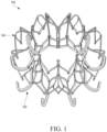
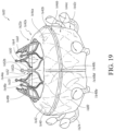
- Figure 1 shows an embodiment of the frame of a multi-portion prosthesis 100 in an expanded configuration.
- the prosthesis 100 can include, but are not limited to, an inner frame 120, an outer frame 140, a valve body 160 (shown in Figures 9-11 ), and a skirt 180 (also shown in Figures 9-11 ).
- a longitudinal axis of the prosthesis 100 may be defined as the central axis that extends through the center of the prosthesis 100 between the upper and lower ends of the prosthesis 100.
- the prosthesis 100 may be oriented such that an upper end of the prosthesis 100 is a proximal portion and a lower end of the prosthesis 100 is a distal portion.
- the illustrated prosthesis 100 may include components which are self-expanding or balloon expandable.
- the inner frame 120 and/or outer frame 140 can be self-expanding.
- the prosthesis 100, as well as other prostheses described herein may be a replacement valve that can be designed to replace a damaged or diseased native heart valve such as a mitral valve, as discussed above. It should be understood that the prosthesis 100, as well as other prostheses described herein, are not limited to being a replacement valve.
- Embodiments of the disclosed prosthesis 100 may have a reduced crimp inner diameter (ID), such as 25Fr, 24Fr, 23Fr, 22Fr, 21Fr, or 20Fr.
- Embodiments of the disclosed prosthesis 100 may have a reduced crimp ID, such as less than 25Fr, 24Fr, 23Fr, 22Fr, 21Fr, or 20Fr.
- Embodiments of the disclosed prosthesis 100 may have a reduced crimp ID, such as greater than 25FR, 24Fr, 23Fr, 22Fr, 21Fr, or 20Fr.
- the prosthesis 100 may have a crimp length of 48, 47, 46, 45, 44, 43, 42, 41, or 40mm.
- the prosthesis 100 may have a crimp length of less than 48, 47, 46, 45, 44, 43, 42, 41, or 40mm. In some embodiments, the prosthesis 100 may have a crimp length of greater than 48, 47, 46, 45, 44, 43, 42, 41, or 40mm. In some embodiments, the prosthesis 100 may only require retrieval forces of 267 N, 245 N, 222 N, 200 N, or 178 N (60, 55, 50, 45, or 40 lbs). to compress the prosthesis 100.
- the prosthesis 100 may only require retrieval forces of less than 267 N, 245 N, 222 N, 200 N, or 178 N (60, 55, 50, 45, or 40 lbs.) to compress the prosthesis 100. In some embodiments, the prosthesis 100 may only require retrieval forces of greater than 267 N, 245 N, 222 N, 200 N, or 178 N (60, 55, 50, 45, or 40 lbs.) to compress the prosthesis 100.
- the multi-portion prosthesis 100 can be made of one or more frames, such as one, two, or three frames.
- the prosthesis 100 can be a dual-frame design, having an inner and an outer frame.
- the inner and outer frame are integrally formed into one frame.
- the frames can be separate and connected together.
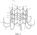
- Figure 2 illustrates the inner frame 120 of the prosthesis 100 with the outer frame 140 removed for clarity.
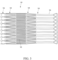
- Figure 3 illustrates a flat pattern of the inner frame 120.
- the inner frame 120 can generally include an inner frame body 122 and an inner frame anchoring feature 124 (if used in a mitral valve, also known as a ventricular or distal anchor).
- the inner frame body 122 can have an upper region 126, an intermediate region 128, and a lower region 130.
- the inner frame body 122 can have a generally cylindrical shape such that the diameters of the upper region 126, the intermediate region 128, and the lower region 130 are generally equivalent.
- the diameters of the upper region 126, the intermediate region 128, and/or the lower region 130 can be different, such as the hourglass shape discussed below with respect to Figures 5A-5E .
- a diameter of the intermediate region 128 can be larger/smaller than the upper region 126 and the lower region 130 such that the frame body 122 has a generally bulbous shape.
- the diameter of the lower region 130 can be larger than the diameter of the upper region 126.
- the diameter of the upper region 126 can be larger than the diameter of the lower region 130.
- the inner frame body 122 has been described and illustrated as being cylindrical or having circular cross-sections, it is to be understood that all or a portion of the inner frame body 122 can have a non-circular cross-section such as, but not limited to, a D-shape, an oval or an otherwise ovoid cross-sectional shape.
- the upper region 126 can be generally positioned supra-annularly (i.e., above the plane of the annulus), the intermediate region 128 can be generally positioned intra-annularly (i.e., within the plane of the annulus), and the lower region 130 can be positioned sub-annularly (i.e., below the plane of the annulus).
- the positioning of the inner frame 120 relative to the annulus can differ.
- the intermediate region 128 can be positioned supra-annularly.
- the inner frame 120 can omit one or more of the upper region 126, the intermediate region 128, and/or the lower region 130.
- the inner frame 120 can include inner frame anchoring feature(s) 124 (in some embodiments ventricular anchors) which can extend generally downwardly and/or radially outwardly at or proximate a lower end of the lower region 130 of the inner frame body 122.
- the inner frame anchoring feature 124 can extend upwardly towards the upper region 126 after extending radially outwards.
- components of the inner frame 120 such as the inner frame anchoring feature 124, can be used to attach or secure the prosthesis 100 to a native valve.
- the inner frame anchoring feature 124 can be used to attach or secure the prosthesis 100 to a native mitral valve.
- the inner frame anchoring feature 124 can be positioned to contact or engage a native mitral valve annulus on a ventricular side, tissue beyond the native valve annulus on a ventricular side, native leaflets on a ventricular side, and/or other tissue at or around the implantation location during one or more phases of the cardiac cycle, such as systole and/or diastole.
- the inner frame anchoring feature 124 can beneficially eliminate, inhibit, or limit upward movement of the prosthesis 100 when subject to upwardly directed forces such as those which are applied on the prosthesis 100 during systole.
- the prosthesis 100 can have nine inner frame anchoring features 124, but in some embodiments may have more or less, such as 1, 2, 3, 4, 5, 6, 7, 8, 9, 10, 11, or 12 inner frame anchoring features 124.
- the inner frame anchoring feature 124 can have ends or tips 124a positioned radially outwardly relative to the longitudinal axis of the prosthesis 100.
- the inner frame anchoring feature 124 can extend at or proximate a lower end of the lower region 130 of the inner frame body 122.
- the inner frame anchoring feature 124 can be formed from a plurality of individual anchors extending from the frame body 122.
- the anchors can extend downwardly from one or more attachment points to the frame body 122 including, but not limited to, lower apices of cells 134b.
- the anchors can bend to extend generally radially outwardly of the longitudinal axis of the prosthesis 100. As shown in the illustrated embodiment, the anchors can extend upwardly towards an end or tip 124a.
- the tips or ends 124a extend upwardly in a direction parallel or generally parallel to the longitudinal axis of the prosthesis 100.
- the tip or end 124a of anchoring feature 124 can extend generally perpendicular to the longitudinal axis of the prosthesis 100. This can beneficially increase the tissue contact area of the tip 124a of the anchor. This increased tissue contact area can beneficially reduce the stress applied by the tip 124a to tissue thereby reducing the amount of pressure and potential for trauma to the tissue.
- the tip or ends 124a of the anchoring feature 124 extend radially inward towards the longitudinal axis and/or radially outward away from the longitudinal axis.
- the tips or ends 124a as described above can advantageously provide atraumatic surfaces that may be used to contact or engage intralumenal tissue without causing unnecessary or undesired trauma to tissue.
- the tips or ends 124a can form flat, substantially flat, curved or other non-sharp surfaces to allow the tips to engage and/or grasp tissue, without necessarily piercing or puncturing through tissue.
- a looped end or looped anchor such as shown in Figure 5A , may assist the frame in not getting caught up on structures at or near the treatment location.
- each loop can be configured so that when the prosthesis 100 is deployed in-situ and the anchoring features 124a expands away from the frame bodies 122, the movement of each loop from a delivered position to a deployed position avoids getting caught on the papillary muscles.
- the inner frame anchoring feature 124 can include a lacrosse-head-shaped tip or end 124a.
- the tips or ends 124a of the inner frame 120 may have a split design such as shown in Figure 24 .
- the anchoring features 124 can include nine individual anchors; however, it is to be understood that a greater number or lesser number of individual anchors can be used.
- the number of individual anchors can be chosen as a multiple of the number of commissures for the valve body 160 (shown in Figure 10 ).
- the inner frame anchoring feature 124 can have three individual anchors (1:1 ratio), six individual anchors (2:1 ratio), nine individual anchors (3:1 ratio), twelve individual anchors (4:1 ratio), fifteen individual anchors (5:1 ratio), or any other multiple of three. It is to be understood that the number of individual anchors need not correspond to the number of commissures of the valve body 160.
- the prosthesis 100 includes anchoring features 124 with twelve anchors each, it is to be understood that a greater number of anchors or a lesser number of anchors can be used.
- the inner frame anchoring feature 124 can include covers and/or cushions 138 to surround or partially surround at least a portion of the inner frame anchoring feature 124, such as the tips or ends 124a.
- the covers and/or cushions 138 can be similar to those described in U.S. Publication No. 2015/0328000 .
- the covers and/or cushions 138 can either fit snuggly around the tips 124a of the inner frame anchoring feature 124 or can have extra padding so that the covers extend radially away from the inner frame body 122.
- covers and/or cushions 138 are attached to a subset of anchors of the inner frame anchoring feature 124 such that a cover and/or cushion 138 is used on every third anchor.
- the outer frame anchoring feature 144 can include covers and/or cushions to surround or partially surround at least a portion of the outer frame anchoring feature 144, such as the tips or ends 144a.
- covers and/or cushions 138 can be used with anchors of the inner frame anchoring feature 124.
- a cover and/or cushion 138 can be used on every other anchor such that there is a 1:2 ratio of covers and/or cushions 138 to anchors.
- a cover and/or cushion 138 can be used on every anchor (as shown in Figures 9-11 ).
- all of the anchors can have the covers and/or cushions with some of the anchors having less cushioning than others.
- all of the anchors can have the padded covers.
- all of the anchors can have the snuggly fitting cushions.
- the cover and/or cushion 138 can be formed from a deformable material. When the top portion of the cover and/or cushion 138 is subject to pressure due to a downwardly directed force, the cover and/or cushion 138 can compress and expand laterally outward. Such a force may be exerted upon the cover and/or cushion 138 when the cover and/or cushion 138, for example, when the cover and/or cushion 138 contacts a ventricular side of the mitral valve annulus during systole. The compression and lateral expansion of cover and/or cushion 138 can increase the surface area of the cover and/or cushion 138 in contact with the tissue, thereby exerting less pressure on the tissue and reducing the potential for trauma.
- the inner frame 120 can be formed from many different materials including, but not limited to a shape-memory metal such as Nitinol.
- the inner frame 120 can be formed from a plurality of struts forming open cells, discussed below.
- the inner frame 120 can have a relatively rigid construction as compared to other components of the prosthesis 100 including, but not limited to, the outer frame 140. This can be achieved, for example, by the dimensions of the struts and by the configuration of the struts.
- the relatively rigid construction can more strongly resist deformation when subject to stress. This can be beneficial during certain portions of the cardiac cycle, such as systole, during which the inner frame 120 may be subject to significant stresses on the inner frame anchoring feature 124.
- the relatively rigid construction can also be beneficial when a valve body 160 is positioned within the inner frame 120 to maintain the shape of the valve body 160. Moreover, the relatively rigid construction can be beneficial when the inner frame 120 is used for a valve-in-valve procedure wherein a supplemental prosthesis is positioned within the inner frame 120.
- the inner frame 120 has been described as having a relatively rigid construction, it is to be understood that in some embodiments the inner frame 120 can have a construction relatively flexible construction.
- the inner frame 120 can have a construction which is about as flexible as, or more flexible than, other components of the prosthesis 100, such as the outer frame 140.
- the diameter of the upper region 126, intermediate region 128, and/or lower region 130 of the inner frame body 122 may be chosen such that the inner frame body 122 is adequately spaced from the body cavity when the prosthesis 100 is positioned within the body cavity.
- the inner frame body 122 may have a diameter which is less than the diameter of the native mitral valve annulus. In situations where the native mitral valve annulus is about 40mm in diameter, the diameter of the inner frame body 122 can be about 30mm. Accordingly, the diameter of the inner frame body 122 may be about 75% of the diameter of the native mitral valve annulus.
- the diameter of the inner frame body 122 may be between about 40% to about 90% of the diameter of the native valve annulus, between about 60% to about 85%, of the diameter of the native valve annulus, between about 70% to about 80% of the diameter of the native valve annulus, any other sub-range between these ranges, or any other percentage as desired. In some embodiments, the diameter of the inner frame body 122 can be in the range of about 20mm to about 40mm when expanded, in the range of about 25mm to about 35mm when expanded, in the range of about 28mm to about 32mm when expanded, any other sub-range within these ranges when expanded, or any other diameter when expanded as desired.
- the inner frame body 122 has been described and illustrated as being cylindrical or having circular cross-sections, it is to be understood that all or a portion of the inner frame body 122 can be have a non-circular cross-section such as, but not limited to, a D-shape, an oval or an otherwise ovoid cross-sectional shape.
- the diameter of portions of the inner frame body 122 such as the upper region 126, intermediate region 128, and/or lower region 130 may be chosen such that the inner frame body 122 is positioned at the periphery of the body cavity.
- the inner frame body 122 may have a diameter which is about equal to the diameter of the native mitral valve annulus.
- Figure 4 illustrates a portion of the inner frame body 122.
- the inner frame body 122 can include a plurality of struts with at least some of the struts forming cells 134a-b. Any number of configurations of struts can be used, such as rings of undulating struts shown forming ellipses, ovals, rounded polygons, and teardrops, but also chevrons, diamonds, curves, and various other shapes.
- the upper row of cells 134a and the lower row of cells 134b can have a diamond/parallelogram or generally diamond/ parallelogram shape.
- the rows of cells 134a-b can be formed via a combination of struts.
- the upper row of cells 134a can be formed from a first set of circumferentially-expansible struts 136a at the top and bottom and a longitudinally extending strut 138.
- the lower row of cells 136b can be formed from the second set of circumferentially-expansible struts 136b on the top and bottom and a longitudinally extending strut 138 on each side, which can be a continuation of the longitudinally extending strut mentioned above.
- the upper row of cells 134a and the lower row of cells 136b can share one circumferentially-expansible strut.
- the bottom strut of the upper row of cells 134a and the top strut of lower row of cells 136b may be shared.
- the first and second sets of struts 136a-b can have a zig-zag or undulating shape forming a repeating "V" shape. While the struts 136a-b are generally described and illustrated as being straight segments, it is to be understood that some or all of the struts 136a-b may not form entirely straight segments.
- the struts 136a-b can include some curvature such that the upper and/or lower apices are curved as shown in Figure 2 .
- the longitudinally extending strut 138 can generally extend from a bottom of the inner frame body 122 to a top of the inner frame body 122.
- the longitudinally extending strut 138 may effectively experience little to no strain during crimping.
- the longitudinally extending strut 138 may be one single strut extending through both rows of cells 134a/134b. Further, as shown each cell of the rows of cells 134a/134b can be circumferentially between longitudinally extending struts 138.
- the upper row of cells 134a and the lower row of cells 134b extend in a direction generally parallel to the longitudinal axis of the prosthesis 100.
- any number of rows of cells can be used and any number of cells may be contained in the rows.
- the number of cells can correspond to the number of anchors or anchor tips forming the inner frame anchoring feature 124.
- both rows of cells 134a-b can have different numbers of cells. Moreover, it is to be understood that fewer or greater numbers of rows of cells can be used.
- the geometry of cells 134a-b can allow the cells 134a-b to foreshorten as the inner frame 120 is expanded.
- one or more of cells 134a-b can allow the inner frame 120 to foreshorten as the inner frame 120 is expanded.
- Foreshortening of the inner frame 120 can be used to secure the prosthesis to intralumenal tissue in a body cavity such as tissue at or adjacent a native valve including, but not limited to, a native valve annulus and/or leaflets.
- expansion of the inner frame 120 can allow the inner frame anchoring feature 124 to extend radially outward and draw closer to tissue of the body cavity, such as a native valve annulus and/or leaflets, to engage tissue of the body cavity.
- the use of longitudinally extending strut 138 can reduce the foreshortening.
- the inner frame 120 can include tabs (or locking tabs) 104 extending from a portion of the inner frame 120.
- the tabs 104 can extend at or proximate an upper end of the upper region 126 of the inner frame body 122 such as upper apices of cells 134a.
- the inner frame 120 can include twelve locking tabs 104, however, it is to be understood that a greater number or lesser number of locking tabs can be used, such as 1, 2, 3, 4, 5, 6, 7, 8, 9, 10, or 11.
- the locking tabs 104 can extend generally upwardly from the upper region 126 of the inner frame body 122 in a direction generally aligned with the longitudinal axis of the prosthesis 100.
- the locking tabs 104 can include a longitudinally-extending strut 132a. At an upper end of the strut 132a, the locking tab 104 can include an enlarged head 132b. As shown, the enlarged head 132b can have a semi-circular or semi-elliptical shape forming a "mushroom" shape with the strut 132a.
- the inner frame 120 can include an eyelet 106.
- the eyelet 106 can be advantageously used to couple the inner frame 120 to an outer frame 140.
- a suture can be passed through the eyelet 106 for coupling to an eyelet 143 of the outer frame 140.
- the eyelet 106 can be used to couple to other components of a prosthesis in which the inner frame 120 is used such as, but not limited to, a valve body and/or a skirt.
- the locking tabs 104 have been described as being attached to the inner frame body 122, it is to be understood that the locking tabs 104 can be attached to other portions of the prosthesis 100 such as, but not limited to, the outer frame body 142.
- the locking tabs 104 can extend from an upper end of an upper region 146 of the outer frame body 142.
- portions of, or the entirety of, the locking tabs 104 can be omitted.
- the strut 132a can be omitted such that the enlarged head 132b and eyelet 106 are positioned at an upper end of the upper region 126 of the inner frame body 122, such as at upper apices of cell 134a.
- each tab 104 can be aligned vertically over an inner frame anchoring feature 124. In some embodiments, each tab 104 is circumferentially offset from an inner frame anchoring feature 124. In some embodiments, there are the same number of tabs 104 as inner frame anchoring features 124. In some embodiments, there are a different number of tabs 104 as inner frame anchoring features 124. There can be more tabs 104 than inner frame anchoring features 124. There can be less tabs 104 as inner frame anchoring features 124.
- the tab 104 can be advantageously used to couple the inner frame 120 with multiple types of delivery systems.
- the shape of the tab 104 can be used to secure the inner frame 120 to a "slot" based delivery system.
- the eyelets 106 can be used to secure the inner frame 120 to a "tether" based delivery system such as those which utilize sutures, wires, or fingers to control delivery of the inner frame 120 and the prosthesis. This can advantageously facilitate recapture and repositioning of the inner frame 120 and the prosthesis in situ.
- the inner frame 120 and prosthesis can be used with the delivery systems described herein, including but not limited to, those described in U.S. Patent Nos. 8,414,644 and 8,652,203 U.S. Publication Nos.
- the tab 104 may be omitted to advantageously the axial dimension between the upper end and the lower end of the inner frame 120 (i.e., the "height" of the inner frame 120 ).
- the inner frame 120 may include features and concepts similar to those disclosed in U.S. Patent Nos. 8,403,983 , 8,414,644 , and 8,652,203 , U.S. Publication Nos. 2011/0313515 , 2014/0277390 , 2014/0277427 , 2014/0277422 , 2015/0328000 , 2018/0021129 , and 2018/0055629 which made a part of this specification. This is inclusive of the entire disclosure and is not in any way limited to the disclosure of the associated frames. Moreover, although the inner frame 120 has been described as including an inner frame body 122 and an inner frame anchoring feature 124, it is to be understood that the inner frame 120 need not include all components.
- the inner frame 120 can include the inner frame body 122 while omitting the inner frame anchoring feature 124.
- the inner frame body 122 and the inner frame anchoring feature 124 have been illustrated as being unitarily or monolithically formed, it is to be understood that in some embodiments the inner frame body 122 and the inner frame anchoring feature 124 can be formed separately. In such embodiments, the separate components can be attached using any of the fasteners and/or techniques described herein.
- the inner frame anchoring feature 124 can be formed separately from the inner frame body 122 and can be attached to the inner frame body 122.
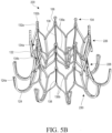
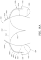
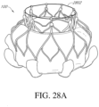
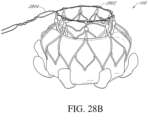
- Figures 5A-5E illustrates an inner frame 220 with an "hourglass” or generally hourglass shape.
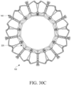
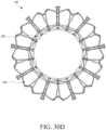
- a full multi-portion replacement valve with an hourglass inner frame is shown with respect to Figures 30A-30D .
- the inner frame 220 can incorporate any or all of the features discussed above with respect to inner frame 120, for example inner frame anchoring feature 124, and the inner frame 120 can incorporate any or all of the features discussed above with respect to inner frame 220.
- Inner frame 220 can include an upper region 226, an intermediate region 228, and a lower region 230. As shown, the intermediate region 228 can have a smaller diameter than the upper region 226, the lower region 230, or both. This can form an hourglass shape wherein the intermediate region 228 is thinner in diameter than both the upper region 226 and the lower region 230.
- the upper region 226 and the lower region 230 can have approximately the same diameter. In some embodiments, the upper region 226 can have a larger diameter than the lower region 230. In some embodiments, the upper region 226 can have a smaller diameter than the lower region 230.
- Figures 5A-5E further illustrates that the inner frame 220 can smoothly transition between the different diameters forming a curved shape.
- the struts making up the inner frame 220 can be curved to form the hourglass.
- the struts can be relatively straight, and there can be inflection points in the struts or at meeting points between the struts.
- the inner frame 220 can be concave.
- a portion of the inner frame 220, such as the upper region 226, the intermediate region 228, and/or the lower region 230 may be concave.
- the inner frame 220 can curve inward, or be thinner, in the middle than at the top and bottom.
- the inner frame 220 can form the hourglass shape in its fully expanded form.
- an hourglass can be shaped from a linear radially inwards taper from the upper region 226 to the intermediate region 228 (so the diameter is smaller at the intermediate region 228 than the upper region 226 ) and a subsequent radially outwards taper (e.g., reversing the taper) from the intermediate region 228 to the lower region 230 (so the diameter is smaller at the intermediate region 228 than the lower region 230 ).
- the frame 220 may have a tapered waist or a narrowed waist.
- the inner frame 220 can taper radially inwards (e.g., reducing diameter) in one direction from one end to the other end.
- the upper region 226 may have the largest diameter
- the inner frame 220 can taper radially inwards to the intermediate region 228, and further radially inwards to the lower region 230.
- the lower region 230 may have the largest diameter
- the inner frame 220 can radially inwards to the intermediate region 228, and further radially inwards to the upper region 226.
- the taper may be smooth, or may be a series of straight portions, like steps. In some embodiments, the taper may occur in 1, 2, 3, 4, 5 straight lines reducing the diameter. In some embodiments, the taper may be curved. In some embodiments, the taper may be linear.
- a portion of the inner frame 220 may be tapered radially inwards, and a different portion may be cylindrical (or generally cylindrical).
- the upper region 226 may be tapered radially inwards, but the intermediate region 228 and/or the lower region 230 may be cylindrical.
- the lower region 230 may be tapered radially inwards, but the intermediate region 228 and/or the upper region 226 may be cylindrical.
- a portion of the inner frame 220 may be tapered radially inwards, and a different portion may be concave (or generally concave).
- the upper region 226 may be tapered radially inwards, but the intermediate region 228 and/or the lower region 230 may be generally.
- the lower region 230 may be tapered radially inwards, but the intermediate region 228 and/or the upper region 226 may be generally.
- each of the valve leaflets can have an inlet end positioned along the decreasing diameter portion of the frame as discussed above.
- the narrower intermediate region 228 can provide for smaller replacement valve leaflets to be used, and the smaller diameter can allow for increased blood flow through the narrower area.
- Embodiments of the inner frame 220 can advantageously reduce thrombogenicity.
- the hourglass shape can help create a vortex which encourages particles to be washed-out during valve opening with high turbulence during closing. This can also include squeezing out any thrombus that may be forming in the gap between leaflets and the frame 220.
- this shape can reduce leaflet thickening, which can cause increased risk of stroke. This can allow for the reduction or avoidance of blood thinners, or at least the avoidance of lifetime blood thinners. This could clinically lead to less anticoagulation, better durability, and lower stroke.
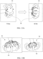
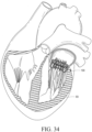
- Figures 5F-5I illustrate the valve leaflets 231 opening in an hourglass shaped frame 220.
- Figure 5F shows the outflow end open
- Figure 5G shows the inflow end open
- Figure 5H shows the outflow end closed
- Figure 5I shows the inflow end closed.
- the inlet end of the valve leaflets 231 can lie flat along the inner frame 220 when the valve is open.
- the valve leaflets 231 may not be parallel to the walls of the frame because the leaflets 231 naturally are inclined outwards in the opened position, causing compression or distortion of the leaflets.
- valve leaflets 231 more naturally rest closer to the frame 220 itself when the valve is open as shown in Figures 5F and 5G , and do not compress or deform.
- the leaflets 231 follow the shape of the hourglass frame 220 when opening, providing for optimal washout.
- the leaflets 231 can be attached generally at the intermediate region 228, so when the leaflets 231 are opened they can extend further radially outwards in the larger diameter regions.
- the hourglass inner frame 220 can allow for the leaflets of the valve body to conform with and/or contact the inner surface of the hourglass inner frame 220.
- the hourglass design can improve washout by reducing any gap between the seamline of the leaflets and the wall of the inner frame 220 on which the leaflets are attached to.
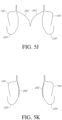
- Figure 5J shows the leaflets 262 in the closed position
- Figure 5K shows the leaflets 262 in the fully open position generally conforming to the inner frame 220.
- the only portions of each of the leaflets 262 that do not contact the frame 220 when opened are the free edges of the leaflets 262 at the outlet end.
- each of the leaflets 262 conform to and/or contact the inner frame 220 of the hourglass shape (e.g., reducing any gap between the leaflets 262 and the interior surface of the inner frame 220 ).
- over 50%, over 75%, over 90%, over 95%, or over 99% of the belly of the leaflets 262 can conform to and contact the interior surface of the inner frame 220 when in the fully open position.
- the free edges of the outlet end of the leaflets 262 do not contact the inner frame 220.
- only the free edges of the outlet end of the leaflets 262 do not contact the inner frame 220.
- the free edges of the outlet end of the leaflets 262 are spaced away from the interior surface of the inner frame 220.
- the hourglass inner frame 220 is shaped to achieve optimal contact between the leaflet surface and the frame surface when the leaflets 262 are fully opened while avoiding contact by the free edges to reduce overall damage to the leaflets during motion. This can improve washout and reduce thrombogenicity, while also providing a more durable leaflet.
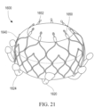
- Figure 31 illustrates an example alternate configuration of the hourglass shape discussed above for the inner frame 220, and can include any or all of the features discussed with respect to frames 120/220 shown in Figures 2 and 5A .
- the inner frame 220' can have a non-hourglass cylindrical shape such as shown in Figure 2 between its upper region 226', intermediate region 228', and lower region 230', as shown in Figure 31 .
- the inner frame 220' can have a substantially constant cross-sectional dimension, e.g., generally circular, between its upper region 226', intermediate region 228', and lower region 230'.
- An additional secondary inner frame 502 can then be attached (permanently or removably) on an inner surface of the inner frame 220'.
- the secondary inner frame 502 can have a generally circular cross section.
- the secondary inner frame 502 can be shaped to form an hourglass within the lumen of the inner frame 220'.
- an intermediate region 288' can have a smaller radial diameter than the upper region 226' and the lower region 230'.
- the upper region 226' and the lower region 230' can have approximately the same dimensions. In other embodiments, the dimensions may be different.
- the transition between different diameters can be smooth, such as with a curve, or can be angular with discrete corners.
- the secondary inner frame 502 can have a concave shape.
- the secondary inner frame 502 can attach generally at proximal (e.g., in the upper region 226 ') and distal (e.g., in the lower region 230 ') ends of the secondary inner frame 502 , and a central portion of the secondary inner frame 502 can be located radially inwards from the ends and from the inner surface of the inner frame 220 '.
- a proximal portion of the secondary inner frame 502 can be attached to the inner frame 220' proximal to where the tabs 104 begin. In some embodiments, a proximal portion of the secondary inner frame 502 can be attached to the inner frame 220' distal to where the tabs 104 begin. In some embodiments, a proximal portion of the secondary inner frame 502 can be attached to the inner frame 220' where the tabs 104 begin.
- a distal portion of the secondary inner frame 502 can be attached to the inner frame 220' proximal to where the inner frame anchoring feature 124 begins bending radially outwards. In some embodiments, a distal portion of the secondary inner frame 502 can be attached to the inner frame 220' distal to where the inner frame anchoring feature 124 begins bending radially outwards. In some embodiments, a distal portion of the secondary inner frame 502 can be attached to the inner frame 220' where the inner frame anchoring feature 124 begins bending radially outwards.
- the secondary inner frame 502 can be attached to the inner frame 220' by, for example, sutures, adhesives, frictional forces, mechanical attachment, or the two frames can be integrally formed together.
- the secondary inner frame 502 can be an "ultra-thin walled" inner frame, such as between 200-400 microns of thickness, though the particular size is not limiting.
- the secondary inner frame 502 may be formed of a plurality of longitudinal strips (e.g., ribs), for example metallic, composite, or polymer strips. The strips could bow inwardly as the inner frame 220' foreshortens upon radial expansion. In some embodiments, the strips could always be bowed inwardly. In some embodiments, the strips could be used in combination with a fabric or polymer.
- the secondary inner frame 502 could generally be a tube of fabric with a plurality of ribs on the outside of the fabric that would push the fabric inwardly to form the hourglass shape.
- a thin braided mesh which can bow inwardly, such as during foreshortening, could be used in conjunction with a fabric as discussed above.
- a cloth or other fabric can be used to form the hourglass shape.
- the cloth could act as a pocket that would fill with blood and harden over time into the particular hourglass shape.
- a balloon could be used to form the hourglass shape where the balloon could be filed with saline or other biocompatible fluid.
- a swellable material could be used to form the secondary inner frame 502.
- the swellable material could absorb water, or other fluid, from blood and swell into the desired shape.
- the secondary inner frame 502 can be advantageous as it leverages the highly stable cylindrical inner frame design of inner frame 220' while still providing the antithrombosis benefit of the hourglass secondary inner frame 502.
- the outer frame 140 can be incorporated into a prosthesis with any of the variations of the described inner frames.
- the outer frame 140 can provide a structure to which various components of the prosthesis 100 can be attached.
- the outer frame 140 can be attached to the inner frame 120 using any of the fasteners and/or techniques described herein including, but not limited to, mechanical fasteners, such as sutures, staples, fabric screws, rivets, interfacing members (e.g., tabs and slots which can be on the inner frame 120 and the outer frame 140 ), and any other type of mechanical fastener as desired, chemical fasteners such as adhesives and any other type of chemical fastener as desired, fastening techniques such as welding, soldering, sintering, and any other type of fastening technique as desired, and/or a combination of such fasteners and techniques.
- the inner frame 120 and the outer frame 140 can be indirectly attached via an intermediate component, such as the skirt 180.
- sutures are used to attached eyelet 143 of the outer frame 140 with eyelet 106 of the inner frame 120.
- the outer frame 140 can be attached to the inner frame 120 at one or more attachment points.
- the outer frame 140 can be tautly attached to the inner frame 120 such that little to no relative movement between the outer frame 140 and the inner frame 120 occurs at the one or more attachment points.
- the outer frame 140 can be loosely attached to the inner frame 120 such that some relative movement between the outer frame 140 and the inner frame 120 can occur at the one or more attachment points.
- the outer frame 140 is illustrated as a separate component from the inner frame 120, it is to be understood that the frames 120, 140 can be unitarily or monolithically formed.
- the outer frame 140 can include an outer frame body 142.
- the outer frame 140 can further include an outer frame anchoring feature 144 (if used in a mitral valve, also known as an atrial or proximal anchor).
- the outer frame may not include an outer frame anchoring feature 144.
- the outer frame body 142 can have an upper region 146, an intermediate region 148, and a lower region 150.
- the upper region 146 can be generally positioned supra-annularly
- the intermediate region 148 can be generally positioned intra-annularly
- the lower region 150 can be positioned sub-annularly.
- the positioning of the outer frame 140 relative to the annulus can differ.
- the outer frame 140 can omit one or more of the upper region 146, the intermediate region 148, and/or the lower region 150.
- the outer frame body 142 When in an expanded configuration such as a fully expanded configuration, the outer frame body 142 can have an enlarged/bulbous shape with the intermediate region 148 and the lower region 150 being larger than the upper region 146, or the intermediate region 148 being larger than the lower region 150 and the upper region 146.
- the bulbous shape of the outer frame body 142 can advantageously allow the outer frame body 142 to engage a native valve annulus, native valve leaflets, or other body cavity, while spacing the inlet and outlet from the heart or vessel wall. This can help reduce undesired contact between the prosthesis 100 and the heart or vessel, such as the atrial and ventricular walls of the heart.
- the bulbous shape can further enhance securement of the outer frame body 142 to the body cavity.
- the bulbous shape can allow the intermediate region 148 to extend further radially outward compared to an anchoring feature.
- the intermediate region 148 can exert a greater radial force on tissue of the body cavity and/or can more completely conform to the tissue of the body cavity, such as the native valve annulus and/or native leaflets.
- the upper region 146 of the outer frame body 142 can include a generally longitudinally-extending section 146a and an outwardly-extending section 146b.
- the longitudinally-extending section 146a can be generally concentric with the inner frame body 122.
- the outwardly-extending section 146b can extend radially outwardly away from the longitudinal axis 102 of the prosthesis 100.
- the outwardly-extending section 146b can extend in a direction that is more perpendicular to the longitudinal axis 102 than parallel and/or in a downward direction from the longitudinally-extending section 146a.
- outwardly-extending section 146b can extend generally perpendicularly to the longitudinal axis 102 and/or in an upward direction from the longitudinally-extending section 146a.
- longitudinally-extending section 146a can be omitted such that the upper region 146 extends radially outwardly at the upper end of the upper region 146.
- the outer frame body 140 can include a bend 152.
- the bend 152 can be about a circumferential axis such that the outwardly-extending section 146b extends in a direction more perpendicular to the longitudinal axis of the outer frame 140 than the longitudinally-extending section 146a.
- the bend 152 can generally form an arc with an angle between about 20 degrees to about 90 degrees.
- the arc can have an angle of about 60 degrees.
- the bend 152 can form an arc with an angle between about 30 degrees to about 60 degrees.
- the radius of curvature of the arc may be constant such that the bend 152 forms a circular arc or may differ along the length of the bend 152.
- the outwardly-extending section 146b can form an angle of between about 20 degrees to about 70 degrees with a plane orthogonal to the longitudinal axis of the prosthesis 100, an angle of between about 30 degrees to about 60 degrees with a plane orthogonal to the longitudinal axis of the prosthesis 100, an angle of between about 40 degrees to about 50 degrees with a plane orthogonal to the longitudinal axis of the prosthesis 100, an angle of about 45 degrees with a plane orthogonal to the longitudinal axis of the prosthesis 100, any subrange within these ranges, or any other angle as desired.
- the outwardly-extending section 146b can form an angle of less than 70 degrees with a plane orthogonal to the longitudinal axis of the prosthesis 100, an angle of less than 55 degrees with a plane orthogonal to the longitudinal axis of the prosthesis 100, an angle of less than 40 degrees with a plane orthogonal to the longitudinal axis of the prosthesis 100, an angle of less than 25 degrees with a plane orthogonal to the longitudinal axis of the prosthesis 100, or less than any other angle as desired.
- the intermediate region 148 of the outer frame body 142 can extend generally downwardly from the outwardly-extending section 146b of the upper region 146. As shown, the intermediate region 148 can have a generally constant diameter from an upper end of the intermediate region 148 to a lower end of the intermediate region 148 such that the intermediate region 148 forms a generally cylindrical shape. However, it is to be understood that the diameters of the upper end, the lower end, and/or the portion therebetween can be different. For example, a diameter of the portion between the upper end and the lower end can be larger than the upper end and the lower end such that the intermediate region 148 has a generally bulbous shape. In some embodiments, the diameter of the lower end can be larger than the diameter of the upper end.
- the diameter of the upper end can be larger than the diameter of the lower end.
- the outer frame body 142 has been described and illustrated as being cylindrical or having circular cross-sections, it is to be understood that all or a portion of the outer frame body 142 can be have a non-circular cross-section such as, but not limited to, a D-shape, an oval or an otherwise ovoid cross-sectional shape.
- the lower region 150 can be curved and/or inclined towards the longitudinal axis of the frame such that the lower ends of the lower region 150 can extend in a direction that is between about 20 degrees to about 80 degrees with respect to a plane parallel to the longitudinal axis, between about 25 degrees to about 70 degrees with respect to a plane parallel to the longitudinal axis between about 30 degrees to about 60 degrees with respect to a plane parallel to the longitudinal axis, about 30 degrees with respect to a plane parallel to the longitudinal axis.
- the lower region 150 can be curved and/or inclined towards the longitudinal axis such that the lower ends of the lower region 150 can extend in a direction generally perpendicular to the longitudinal axis.
- the outer frame body 142 in an expanded configuration can have a diameter at its widest portion of between about 30mm to about 60mm, between about 35mm to about 55mm, about 40mm, any sub-range within these ranges, or any other diameter as desired. In some embodiments, the outer frame body 142 in an expanded configuration can have a diameter at its narrowest portion between about 20mm to about 40mm, any sub-range within these ranges, or any other diameter as desired. In some embodiments, the outer frame body 142 in an expanded configuration can have a diameter at a lower end of the lower region 150 between about 20mm to about 40mm, any sub-range within these ranges, or any other diameter as desired.
- the ratio of the diameter of the outer frame body 142 at its widest portion to the diameter of the frame body 142 at its narrowest portion can be about 3:1, about 5:2, about 2:1, about 3:2, about 4:3, any ratio within these ratios, or any other ratio as desired.
- the outer frame body 142 can have an axially compact configuration relative to the radial dimension.
- the outer frame body 142 in an expanded configuration can have an the axial dimension between the upper and lower ends of the outer frame body 142 (i.e., the "height" of the outer frame body 142 ) of between about 10mm to about 40mm, between about 18mm to about 30mm, about 20mm, any sub-range within these ranges, or any other height as desired.
- the ratio of the diameter of the largest portion of the outer frame body 142 to the height of the outer frame body 142 when the frame is in its expanded configuration can be about 3:1, about 5:2, about 2:1, about 3:2, about 4:3, about 13:10, about 5:4, or about 1:1.
- the width at the largest portion of the outer frame body 142 can be greater than the height of the outer frame body 142.
- the outer frame body 142 can include a plurality of struts with at least some of the struts forming cells 154. Any number of configurations of struts can be used, such as rings of undulating struts shown forming ellipses, ovals, rounded polygons, and teardrops, but also chevrons, diamonds, curves, and various other shapes.
- the cells 154 can have an irregular octagonal shape such as a "teardrop" shape.
- the cells 154 can be formed via a combination of struts.
- the upper portion of cells 154 can be formed from a set of circumferentially-expansible struts 156a having a zig-zag or undulating shape forming a repeating "V" shape.
- the circumferentially-expansible struts 156a can be inclined or curved radially outwardly away from the longitudinal axis of the prosthesis 100 such that an upper portion of the struts 156a are positioned closer to the longitudinal axis of the prosthesis 100 than the lower portion of the struts 156a.
- the bottom portion of cells 154 can be formed from a set of struts 156b extending downwardly from a central or generally central location of each of the "V" shapes.
- the struts 156b can extend along with a plane parallel to and/or extending through the longitudinal axis of the prosthesis 100.
- struts 156 are generally described and illustrated as being straight segments, it is to be understood that some or all of the struts 156 may not form entirely straight segments.
- the struts 156 can include some curvature such that the upper and/or lower apices are curved.
- the geometry of cells 154 can allow the cells 154 to foreshorten as the outer frame 140 is expanded. As such, one or more of cells 154 can allow the outer frame 140 to foreshorten as the outer frame 140 is expanded. Foreshortening of the outer frame 140 can be used to secure the prosthesis to intralumenal tissue in a body cavity such as tissue at or adjacent a native valve including, but not limited to, a native valve annulus and/or leaflets. For example, expansion of the outer frame 140 can allow the outer frame 140 to exert a radially outward force against the tissue at or adjacent the native valve, such as the native valve annulus and/or leaflets.
- Figures 7A-7B illustrate a flat pattern of the outer frame 140 in the compressed ( Figure 7A ) and expanded ( Figure 7B ) position.
- struts 156b are generally held circumferentially between struts 156a in both the compressed and expanded position.
- the struts 156a/156b can be asymmetric, thus making some struts compressible/expandably weaker than other struts.
- struts 156b can have a different width/thickness than struts 156a. While symmetric cells can have uneven expansion and crimp, the asymmetric cells disclosed herein can have even expansion and crimping. Further, having the different width/thickness can promote stability of the valve.
- struts 156a/156b are the same thickness/width (e.g., are symmetric).
- struts 156b can be 100%, 95%, 90%, 80%, 70%, 60%, 50%, 40%, or 30% the thickness/width of struts 156a. In some embodiments, struts 156b can be less than 100%, 95%, 90%, 80%, 70%, 60%, 50%, 40%, or 30% the thickness/width of struts 156a. In some embodiments, struts 156b can be greater than 95%, 90%, 80%, 70%, 60%, 50%, 40%, or 30% the thickness/width of struts 156a.
- Figures 7C-7D illustrates another embodiment of a flat pattern of an outer frame 140, and can include any or all of the features discussed above with respect to Figures 7A-7B .
- the outer frame 140 can include a notch 151 that partially extends into the strut 156a' at the connection between the struts 156a'/156b'.
- the notch can be rounded, as shown in Figure 7D , or may be triangular, squared, or another cut pattern and the particular shape of the notch is not limiting.
- the notch 151 can save approximately 0.25mm of material per strut, allowing for a total reduction of 4.55mm in circumference as compared to non-notched configurations. Further, as the peak force is generally at the connection of the struts 156a'/156b', and the design can reduce the overall straight on the outer frame 140.
- the outer frame 140 can include a tab 145 extending proximally away from the eyelet 143, such as also shown in the following Figures 8A-8B .
- This can allow for better attachment between the outer frame and the inner frame, for example by allowing for a second aperture per strut and more area for sutures to attach, and can provide for an alternative attachment mechanism.
- the tab 145 can be, for example, a mushroom tab as disclosed herein with respect to the inner frame 120, and may allow for attachment into the delivery system.
- Figures 8A-8B illustrate flat patterns of alternative configurations of the outer frame 140, and can include any or all of the features disclosed above with respect to Figures 7A-7D .
- Figure 8A illustrates an outer frame 140 having outer frame anchoring feature 144, an expanded version of which is shown in Figure 12 .
- both Figures 8A and 8B include tabs 145 extending upwards.
- the outer frame anchoring feature 144 can extend outwardly relative to the longitudinal axis 102 of the prosthesis 100.
- the outer frame anchoring feature 144 can extend at or proximate the juncture between the upper region 146 and the intermediate region 148 of the outer frame body 142.
- the outer frame anchoring feature 144 can extend in a direction that is more perpendicular to the longitudinal axis 102 than parallel and/or can extend in a downward direction from the longitudinally-extending section 146a.
- the outer frame anchoring feature 144 can extend in a direction generally aligned with the outwardly-extending section 146b of the upper region 146.
- the outer frame anchoring feature 144 can extend generally perpendicularly to the longitudinal axis 102 and/or in an upward direction.
- the outer frame anchoring feature 144 can extend in a direction that is more perpendicular to the longitudinal axis of the prosthesis 100 than parallel. As shown, the outer frame anchoring feature 144 can extend in a downward direction generally parallel to the outwardly-extending section 146b. In some embodiments, the outer frame anchoring feature 144 can extend generally perpendicularly to the longitudinal axis 102 and/or in an upward direction.
- the outer frame 140 can include tabs 118 extending from a portion of the outer frame 140 such as an upper end of the outer frame 140.
- the tabs 118 can include an eyelet 143.
- the tab 118 can be advantageously used to couple the outer frame 140 to an inner frame 120 of the prosthesis.
- a suture can be passed through the eyelet 143 for coupling to an inner frame 120.
- the tabs 118 can be used to couple to other components of a prosthesis in which the outer frame 140 is used such as, but not limited to, a valve body and/or a skirt.
- the tab 118 can be advantageously used to couple the outer frame 140 with multiple types of delivery systems.
- the shape of the tab 118 can be used to secure the outer frame 140 to a "slot" based delivery system.
- the eyelets 120 can be used to secure the outer frame 140 to a "tether" based delivery system such as those which utilize sutures, wires, or fingers to control delivery of the outer frame 140 and the prosthesis. This can advantageously facilitate recapture and repositioning of the outer frame 140 and the prosthesis in situ.
- the outer frame 140 and prosthesis can be used with the delivery systems described herein, including but not limited to, those described in U.S. Patent Nos. 8,414,644 and 8,652,203 and U.S. Publication Nos. 2015/0238315 .
- a tab can be positioned at an end of a strut similar to locking tabs 232.
- anchoring features 124, 144 While the below discusses anchoring features 124, 144, it will be understood that the prosthesis 100 may not include feature 144.
- One or both anchoring features 124, 144 (if used) can contact or engage a native valve annulus, such as the native mitral valve annulus, tissue beyond the native valve annulus, native leaflets, and/or other tissue at or around the implantation location during one or more phases of the cardiac cycle, such as systole and/or diastole.
- one or both anchoring features 124, 144 do not contact or engage, or only partially contact or engage, a native valve annulus, such as the native mitral valve annulus, tissue beyond the native valve annulus, native leaflets, and/or other tissue at or around the implantation location during one or more phases of the cardiac cycle, such as systole and/or diastole.
- a native valve annulus such as the native mitral valve annulus
- both the inner frame anchoring feature 124 and the outer frame anchoring feature 144 can be sized to contact or engage the native mitral valve annulus.
- the anchoring features 124, 144 (if used) and anchor tips 124a, 144a (if used) are preferably located along the prosthesis 100 with at least part of the foreshortening portion positioned between the anchoring features 124, 144 (if used) so that a portion of the anchoring features 124, 144 (if used) will move closer together with expansion of the prosthesis 100. This can allow the anchoring features 124, 144 (if used) to close in on opposite sides of the native mitral annulus to thereby secure the prosthesis at the mitral valve.
- the anchoring features 124, 144 can be positioned such that the anchoring features 124, 144 (if used) do not contact opposing portions of the native mitral annulus at the same time.
- the inner frame anchoring feature 124 is sized to contact or engage the native mitral valve annulus whereas the outer frame anchoring feature 144 (if used) is sized to be spaced from the native mitral valve annulus. This can be beneficial when outer frame anchoring feature 144 (if used) is used to provide stabilization and help align the prosthesis.
- the anchoring features 124, 144 (if used) can be positioned such that the anchoring features 124, 144 (if used) grasp opposite side of the native mitral annulus.
- anchoring features 124, 144 have been illustrated as extending from the lower end of the lower region 130 of the inner frame body 122 and at a junction between the upper region 146 and the intermediate region 148 of the outer frame body 142 respectively, it is to be understood that the anchoring features 124, 144 (if used) can be positioned along any other portion of the prosthesis 100 as desired. Moreover, while two anchoring features 124, 144 (if used) have been included in the illustrated embodiment, it is to be understood that a greater number or lesser number of sets of anchoring features can be utilized.
- Components of the outer frame 140 can be used to attach or secure the prosthesis 100 to a native valve, such as a native mitral valve.
- a native valve such as a native mitral valve.
- the intermediate region 148 of the outer frame body 142 and/or the outer anchoring feature 144 can be positioned to contact or engage a native valve annulus, tissue beyond the native valve annulus, native leaflets, and/or other tissue at or around the implantation location during one or more phases of the cardiac cycle, such as systole and/or diastole.
- the outer frame body 142 can beneficially eliminate, inhibit, or limit downwardly directed forces such as those which are applied on the prosthesis 100 during diastole and/or upwardly directed forces such as those which are applied on the prosthesis 100 during systole.
- the outer frame body 142 can be sized and positioned relative to the inner frame anchoring feature 124 such that tissue of the body cavity positioned between the outer frame body 142 and the inner frame anchoring feature 124, such as native valve leaflets and/or a native valve annulus, can be engaged or pinched to further secure the prosthesis 100 to the tissue.
- the lower region 150 of the outer frame body 142 can be positioned at or proximate a tip or end of the inner frame anchoring feature 124. As shown, the lower region 150 of the outer frame body 142 is positioned such that at least a portion is positioned radially inward of and below the inner frame anchoring feature 124. In some embodiments, a portion of the outer frame 140, such as the lower region 150, can be attached to the inner frame body 122 via one or more tethers or sutures to limit the outward extension of the outer frame 140 relative to the inner frame body 122. This can beneficially maintain a portion of the outer frame 140 between the inner frame body 122 and the inner frame anchoring feature 124. Although the inner frame anchoring feature 124 is shown extending from the inner frame body 122, it is to be understood that such an anchoring feature can extend from the outer frame body 140.
- an inner frame 120 and an outer frame 140 can be beneficial for the design of the prosthesis in that the inner frame 120 can be designed to suit the structure of the valve body 160 and the outer frame 140 can be designed to suit the anatomy of the body cavity in which the prosthesis 100 is to be used.
- the valve body 160 shown in Figure 10
- the inner frame 120 can advantageously have a smaller shape and/or size to support the valve body 160 while the outer frame 140 can have a larger shape and/or size to secure the prosthesis 100 to the body cavity.
- the shape of the outer frame 140 can beneficially enhance hemodynamic performance.
- the shape of the outer frame 140 with a larger, generally cylindrical intermediate region 148 can allow for significant washout on an underside of the valve body 160. This washout can beneficially reduce the risk of thrombosis or clot formation under and around the valve body 160.
- the outer frame 140 can be formed from many different materials including, but not limited to, a shape-memory metal such as Nitinol.
- the outer frame 140 can be formed from a plurality of struts forming open cells.
- the outer frame 140 can have a more flexible construction as compared to other components of the prosthesis 100 such as, but not limited to, the inner frame 120. This can be achieved, for example, by the dimensions of the struts and by the configuration of the struts. For example, fewer struts, thinner struts, and/or a different material for the struts can be used.
- the more flexible construction can allow the outer frame 140 to better conform to the anatomy of the body cavity, such a native valve annulus and/or native leaflets.
- the outer frame 140 can have a construction which is about as rigid as, or more rigid than, other components of the prosthesis 100, such as the inner frame 120.
- the outer frame 140 may include features and concepts similar to those disclosed in U.S. Patent Nos. 8,403,983 , 8,414,644 , and 8,652,203 , U.S. Publication Nos. 2011/0313515 , 2014/0277390 , 2014/0277427 , 2014/0277422 , 2018/0021129 , 2018/0055629 , and 2015/0328000 .
- the outer frame 140 has been described as including an outer frame body 142 and an outer frame anchoring feature 144, it is to be understood that the outer frame 140 need not include all components.
- the outer frame 140 can include the outer frame body 142 while omitting the outer frame anchoring feature 144.
- the outer frame body 142 and the outer frame anchoring feature 144 have been illustrated as being unitarily or monolithically formed, it is to be understood that in some embodiments the outer frame body 142 and the outer frame anchoring feature 144 can be formed separately. In such embodiments, the separate components can be attached using any of the fasteners and techniques described herein.
- the outer frame anchoring feature 144 can be formed separately from the outer frame body 142 and can be attached to the outer frame body 142.
- Figures 9-11 illustrate the prosthesis 100 with the skirt 180.
- the skirt 180 can be attached to the inner frame 120 and/or outer frame 140 (or any of the alternate frames disclosed herein). As shown, the skirt 180 can be positioned around and secured to a portion of, or the entirety of, the exterior of the inner frame 120 and/or outer frame 140, such as in between the two frames 120/140. The skirt 180 can also be secured to a portion of the valve body 160. The skirt 180 can follow the contours of the outer frame 140, such as the contours of the upper region 146, the intermediate region 148, and/or the lower region 150. In some embodiments, the skirt 180 can be used to attach the outer frame 140 to the inner frame 120.
- the skirt 180 can be positioned around and secured to a portion of, or the entirety of, an interior of the inner frame 120 and/or the outer frame 140. Moreover, it is to be understood that while the skirt 180 can follow the contours of portions of the inner frame 120 and the outer frame 140, at least a portion of the skirt 180 can be spaced apart from at least a portion of both the inner frame 120 and the outer frame 140. In some embodiments, the skirt 180 can be spaced apart from the upper region 146 of the outer frame 140. For example, the skirt 180 can be positioned below the upper region 146. In such an embodiment, the spaced-apart portion of the skirt 180 can be loose such that the skirt 180 is movable relative to the upper region 146 or can be taut such that the skirt 180 is generally fixed in position.
- the skirt 180 can be annular and can extend entirely circumferentially around the inner frame 120 and/or outer frame 140.
- the skirt 180 can prevent or inhibit backflow of fluids, such as blood, around the prosthesis 100.
- the skirt 180 can create an axial barrier to fluid flow exterior to the inner frame 120 and/or outer frame 140 when deployed within a body cavity such as a native valve annulus.
- the skirt 180 can encourage tissue in-growth between the skirt 180 and the natural tissue of the body cavity. This may further help to prevent leakage of blood flow around the prosthesis 100 and can provide further securement of the prosthesis 100 to the body cavity.
- the skirt 180 can be tautly attached to the inner frame 120 and/or outer frame 140 such that the skirt 180 is generally not movable relative to the inner frame 120 and/or outer frame 140. In some embodiments, the skirt 180 can be loosely attached to the inner frame 120 and/or outer frame 140 such that the skirt 180 is movable relative to the inner frame 120 and/or outer frame 140.
- the skirt 180 can be formed from a material such as knit polyester (e.g., polyethylene terephthalate (PET), polyvalerolactone (PVL)) or any other biocompatible material such as those which are wholly or substantially fluid impermeable, flexible, stretchable, deformable, and/or resilient.
- the skirt 180 and/or the liner may be made from the same or similar materials.
- the skirt 180 can be formed as separate components.
- the components can be attached together using any of the fasteners and/or techniques described herein including, but not limited to, mechanical fasteners, such as sutures, staples, screws, rivets, interfacing members (e.g., tabs and slots), and any other type of mechanical fastener as desired, chemical fasteners such as adhesives and any other type of chemical fastener as desired, fastening techniques such as welding, soldering, sintering, and any other type of fastening technique as desired, and/or a combination of such fasteners and techniques.
- mechanical fasteners such as sutures, staples, screws, rivets, interfacing members (e.g., tabs and slots)
- chemical fasteners such as adhesives and any other type of chemical fastener as desired
- fastening techniques such as welding, soldering, sintering, and any other type of fastening technique as desired, and/or a combination of such fasteners and techniques.
- the skirt 180 can be attached to the inner frame 120, such as at one of the struts.
- the skirt 180 can attach to longitudinally extending strut 138 or the circumferentially extending struts 136a/13b.
- the skirt 180 can be attached through sutures, adhesives, tying, etc. and the attachment is not limiting.
- the skirt 180 can also be attached to the outer frame 140.
- skirt 180 As the skirt 180 is attached to the inner frame 120, when the prosthesis 100 first begins to crimp, such as for retraction/retrieval, the skirt 180 is pulled inwardly with the inner frame 180. Thus, the skirt 180 can be tucked between the struts of the outer frame 140. It can be advantageous to perform this automatic tucking as in some embodiments a large amount of material (such as cloth) of the outer skirt 180 is needed to seal particularly large annuluses. Accordingly, the skirt 180 can bunch up/prevent low profile crimping or require large amounts of force to fully crimp the prosthesis because of the skirt 180 "clogging" the struts and preventing closure. Thus, manual tucking can be avoided and retrieval forces can be removed.
- Figures 13A-13B illustrate the automatic tucking of the cloth into the prosthesis 100.
- the ventricular portion (e.g., the bottom, distal, or lower portion) of the skirt 180 may act as a "curtain" around the inner frame 220.
- the ventricular portion 182 of the outer skirt 180 is not attached to the outer frame 140 as the outer frame 140 ends above this portion of the skirt 180. This portion 182 is also not attached to the inner frame 220 until the bottom of the skirt 180.
- the portion 182 of the outer skirt 180 is circumferentially unattached, and is instead held generally in tension between an inner surface of the outer frame 140 and the an outer surface of the ventricular or distal end of the inner frame 220.
- the outer skirt 180 allows the outer skirt 180 to flex or bend when radial pressure is applied to it.
- the outer skirt 180 has the flexibility to conform to a valve annulus, such as the mitral valve annulus, which can create an improved seal between the prosthesis 100 and the annulus.
- a valve annulus such as the mitral valve annulus
- This can be especially advantageous as by having the curtain configuration and a reduced outer frame 140, the overall profile of the device can be reduced.
- the outer frame 140 can compress more easily against the inner frame 220 and the overall structure can compress to a much smaller diameter as compared to a device having an outer frame extending all the way to the inner frame anchoring features 124.
- Figures 14A - B and 15 illustrate an embodiment of a prosthesis 100 which can improve the stiffness of the inner frame anchoring features 124 using the outer skirt 180.
- the skirt 180 can be added into the prosthesis 100 to increase the stiffness of the inner frame anchoring features 124, for example by distributing force between the inner frame 120, the outer frame 140, and the added stiffness improving material 192 (which can be a portion of skirt 180 ).
- the stiffness improving material 192 can be incorporated into, or can be the same, as the skirt 180 or can be its own separate material.
- Figures 14A-B illustrate an example embodiment of the improved stiffness.
- the prosthesis can include the inner frame 120 having the inner frame anchoring features 124, the outer frame 140, and the stiffness improving material 192.
- the stiffness improving material 192 can be cloth, fabric, or other soft material such as discussed above with respect to skirt 180.
- the stiffness improving material 192 can be attached at three different points on the prosthesis 100.
- the stiffness improving material 192 can be located between the frames 120/140 our radially outwards of both frames 120/140.
- the stiffness improving material 192 can be attached to a lower end of the outer frame 140. This stiffness improving material 192 can be attached at the base apices of struts 156a or at the base apices of struts 156b. However, the stiffness improving material 192 can be attached at any particular point of the outer frame 140. In some embodiments, the stiffness improving material 192 can be attached to outer frame anchoring feature 144 if used. The attachment can be sutures, threads, chemical adhesives, mechanical fastening, and the particular attachment is not limiting.
- the stiffness improving material 192 can be attached on the inner frame anchoring features 124. For example, it can be attached approximately midway along the inner frame anchoring features 124, such as shown in Figures 14A-B. However, the stiffness improving material 192 can be attached at any point along the inner frame anchoring features 124, and the particular location is not limiting.
- the attachment can be generally at the midpoint of the stiffness improving material 192, but this is not limiting.
- the attachment can be sutures, threads, chemical adhesives, mechanical fastening, and the particular attachment is not limiting.
- the second end of the stiffness improving material 192 can be attached to a portion of the inner frame 120.
- it can be attached at the longitudinally extending strut 138 or at the circumferentially extending struts 136b.
- the stiffness improving material 192 can be attached at the first and second ends generally at the same longitudinal position.
- the stiffness improving material 192 is attached to the inner frame 120 at a different longitudinal position than where it is attached to the outer frame 140.
- the stiffness improving material 192 is attached to the inner frame 120 at a lower longitudinal position (e.g., towards the inner frame anchoring features 124 ) than where it is attached to the outer frame 140.
- the stiffness improving material 192 is attached to the inner frame 120 at a higher longitudinal position (e.g., away from the inner frame anchoring features 124 ) than where it is attached to the outer frame 140.
- the attachment can be sutures, threads, chemical adhesives, mechanical fastening, and the particular attachment is not limiting.
- Figure 14A shows the prosthesis 100 in the expanded position.
- the stiffness improving material 192 is pulled taught, thereby applying an upward force on the stiffness improving material 192 and thus the inner frame anchoring features 124.
- the stiffness improving material 192 becomes slack, thus reducing the stiffness of the inner frame anchoring features 124 and facilitating retrieval.
- the stiffness improving material 192 can extend along a circumference of the prosthesis 100 such as discussed above with respect to skirt 180. In some embodiments, the stiffness improving material 192 can extend partially around the circumference of the prosthesis 100. In some embodiments, multiple the stiffness improving material 192 can be used. In some embodiments, the stiffness improving material 192 is attached to every inner frame anchoring features 124. In some embodiments, the stiffness improving material 192 is attached to every other inner frame anchoring features 124. In some embodiments, the stiffness improving material 192 is attached to every third inner frame anchoring features 124.
- the use of the stiffness improving material 192 can create a "sealed void", “clot pocket”, “cloth pocket”, or “pocket” between the inner frame 120 and the outer frame 140.
- the pocket is an empty volume covered with the stiffness improving material 192 between the inner frame 120 and the outer frame 140. This can reduce thrombosis formation on the prosthesis 100 as in an open configuration blood can flow through struts in the frames and circulate between the frames causing thrombus.
- Figure 15 illustrates an alternate stiffness improving material 192 where the stiffness improving material 192 is one or more sutures.
- the stiffness improving material 192 is one or more sutures.
- a single suture can extend around the circumference of the prosthesis 100, but in some embodiments multiple discrete sutures can be used.
- the sutures extend between outer frame anchoring features 144 and circumferentially adjacent inner frame anchoring feature 124, thus forming a "zig-zag" pattern around the prosthesis 100.
- the stiffness improving material 192 can pass through apertures at the ends of the outer frame anchoring features 144.
- the stiffness improving material 192 can either be tied in or pass through the apertures.
- the stiffness improving material 192 can then attach to material around the inner frame anchoring feature 124.
- the stiffness improving material 192 can wrap around the inner frame anchoring features 124 themselves, such as forming a loop in the suture or extending through an aperture or around a protrusion in the inner frame anchoring feature 124.
- outer frame anchoring features 144 may not be used and the sutures can attach directly to the outer frame 140 such as discussed above.
- the use of the stiffness improving material 192 of any of the above embodiments can prevent the outer frame 140 from crimping inside the inner frame 120. This can be done by providing sufficient tension with the stiffness improving material 192 to prevent insertion of lower portions of the outer frame 140 from entering the inner frame 120.
- the prosthesis 100 has been described as including an inner frame 120, an outer frame 140, a valve body 160, and a skirt 180, it is to be understood that the prosthesis 100 need not include all components.
- the prosthesis 100 can include the inner frame 120, the outer frame 140, and the valve body 160 while omitting the skirt 180.
- the components of the prosthesis 100 have been described and illustrated as separate components, it is to be understood that one or more components of the prosthesis 100 can be integrally or monolithically formed.
- the inner frame 120 and the outer frame 140 can be integrally or monolithically formed as a single component.
- the prosthesis 100 may only include a single frame.
- the concepts discussed above, such as the hourglass shape, the strut/cell shape, etc. can be incorporated into a single frame prosthesis.
- the prosthesis 100 may be applicable to a prosthesis having more than just the inner frame 120 and the outer frame 140.
- the concepts discussed above, such as the hourglass shape, the strut/cell shape, etc. can be incorporated into a prosthesis having 1, 2, 3, 4, 5, or 6 frames.
- Figure 16 illustrates an embodiment of the prosthesis 100 being radially compressed.
- the outer frame 140 can have a substantial angular change (e.g., bend or shoulder) between the upper region 146 and the intermediate region 148 and the lower region 150.
- the bend could be 50, 60, 70, 80, 90, or 100 degrees.
- the bend could be greater than 50, 60, 70, 80, 90, or 100 degrees.
- the bend could be less than 50, 60, 70, 80, 90, or 100 degrees.
- the lower region 150 may have approximately the same radial diameter than the intermediate region 148.
- the lower region 150 may have smaller radial diameter than the intermediate region 148. This can, for example, allow the frame to act as a "plug" or "cork” within the mitral valve annulus.
- the mitral valve annulus, or other structural heart features may apply radially inward pressure on the prosthesis 100, causing some indents, bends, or compression of the intermediate region 148 or the lower region 150, which can allow the prosthesis 100 to achieve a tighter fit.
- the prosthesis 100 can have a scalloped inflow. This can help reduce atrial projection and promote flow prior to release from the delivery system.
- Figure 17B illustrates an embodiment of an inner frame anchoring feature 124.
- the distal tip can be covered by a first material 121, such as ePTFE or other plastic, while the main curve can be covered by a second material 123.
- the second material 123 can be a foam or fabric.
- the second material 123 can be a PET-covered polyurethane foam, though this is not limiting.
- the two materials can be attached together, such as by suturing, shrinkage, friction, or mechanical fastening, or can be separate.
- Figure 29 illustrates an alternate embodiment of a prosthesis 100 which can include any or all of the features described herein.
- the outer frame 140 can have a bulbous (or generally bulbous shape).
- the outer frame 140 can have a shoulder as shown in Figure 29 .
- the different iterations of the prosthesis frame disclosed above can provide advantageous for the implantation procedure.
- the prosthesis 100 expands from a compressed configuration to an expanded configuration during delivery. This can be done in or around the mitral annulus.
- the outer frame 140 including any of the variations of the outer frame 140 discussed above, is expanded, it can circumferentially press against tissue on the circumference of the mitral annulus. This shape can provide a form of retention to stop the prosthesis 100 from going into the left ventricle in diastole, and generally stabilize the prosthesis 100 in the mitral valve annulus.
- the prosthesis 100 outer frame 140 may not fully expand, and may be minimally to partially compressed within the mitral annulus.
- the prosthesis 100 may fully expand, and be retained within the left ventricle by the inner frame anchoring features and in the left atrium by the bulbous shape, for example including the shoulders, of the outer frame 140.
- after release of the prosthesis 100 it can be moved towards the left ventricle by the heart where it will then "cork" in the mitral annulus.
- the valve body 160 can be positioned within the inner frame 120.
- the valve body 160 can be a replacement heart valve which includes a plurality of valve leaflets 262.
- the valve leaflets 262 can include a first edge, second edge, and tabs for attaching the valve leaflets 262 together at commissures of the valve body 160.
- the tabs can be used to secure the valve leaflets 262 to the inner frame 120.
- the first edge can be an arcuate edge and can be generally fixed in position relative to the frame 120.
- the second edge can be a freely moving edge which can allow the valve body 160 to open and close.
- the plurality of valve leaflets 262 can function in a manner similar to the native mitral valve, or to any other valves in the vascular system as desired.
- the plurality of valve leaflets 262 can open in a first position and then engage one another to close the valve in a second position.
- the plurality of valve leaflets 262 can be made to function as a one way valve such that flow in one direction opens the valve and flow in a second direction opposite the first direction closes the valve.
- the valve body 160 can open allow to blood to flow through the valve body 160 in a direction from an upper end to a lower end.
- the valve body 160 can close to inhibit blood flow through the valve body 160 in a direction from the lower end to the upper end.
- the valve body 160 can be positioned such that the valve body 160 can open to allow blood to flow through the valve body 160 in a proximal-to-distal direction and close to inhibit blood flow in a distal-to-proximal direction.
- the valve body 160 can be constructed so as to open naturally with the beating of the heart. For example, the valve body 160 can open during diastole and close during systole.
- the valve body 160 can replace a damaged or diseased native heart valve such as a diseased native mitral valve.
- the valve body 160 can include a liner.
- the liner can be used to assist with fluid flow through and/or around the prosthesis 100, such as through and around the inner frame 120 and the valve leaflets 262.
- the liner can surround at least a portion of the valve leaflets 262 and be connected to one or more of the valve leaflets 262.
- the one or more valve leaflets 262 can be attached to the liner along the first edge of the valve leaflets 262.
- the liner can be positioned within the interior of the inner frame 120 and can form an inner wall of the prosthesis 100.
- the liner can be positioned such that the liner is radially inward, relative to the longitudinal axis of the prosthesis 100, from the struts 136a-c of the inner frame 120.
- the fluid pathway towards the valve leaflets 262 can be relatively smooth.
- the liner can at least be partially positioned along an exterior of the inner frame 120 and/or outer frame 140 such that at least a portion of the liner is radially outward, relative to the longitudinal axis of the prosthesis 100, from struts of the inner frame 120 and/or outer frame 140.
- the liner can be positioned along an upper or inlet side of the inner frame 120.
- the liner can extend from the first edge of the valve leaflets 262 towards the upper end of the inner frame 120.
- the liner can also extend below the first edge of the valve leaflet 262 towards the lower end of the inner frame 120.
- the liner can also be made to move with foreshortening portions of the inner frame 120.
- the liner can extend the entire length of the inner frame 120 or the inner frame body 122. In other embodiments, it can extend along only part of the length of the inner frame body 122 as shown. In some embodiments, the ends of the valve leaflets 262 can coincide with ends of the liner. In addition, one or more of the ends of the inner frame body 122 can coincide with the ends of the liner. An end of the liner can be positioned between the upper end of the inner frame 120 and the valve leaflets 262. The end of the liner can extend above an upper end of the inner frame body 122 and extend along a portion of the locking tabs. In some embodiments, the end of the liner can be positioned at or proximate an uppermost portion of the first or arcuate edge of the valve leaflet 262 below the upper end of the inner frame body 122.
- the liner may extend along the length of the leaflets, but is not connected to them.
- the liner is attached to the inner frame 120 and at least a portion of the leaflets 262, such as the first or arcuate edge, is attached to the liner. Portions of the valve leaflets 262, such as the portions of the first edge and/or tabs, can also be attached to the inner frame 120.
- the liner and/or the valve leaflets 262 can be attached to the inner frame 120 or to each other using any of the fasteners and/or techniques described herein including, but not limited to, mechanical fasteners, such as sutures, staples, screws, rivets, interfacing members (e.g., tabs and slots), and any other type of mechanical fastener as desired, chemical fasteners such as adhesives and any other type of chemical fastener as desired, fastening techniques such as welding, soldering, sintering, and any other type of fastening technique as desired, and/or a combination of such fasteners and techniques.
- mechanical fasteners such as sutures, staples, screws, rivets, interfacing members (e.g., tabs and slots)
- chemical fasteners such as adhesives and any other type of chemical fastener as desired
- fastening techniques such as welding, soldering, sintering, and any other type of fastening technique as desired, and/or a combination of such fasteners and techniques.
- the liner can be constructed in multiple different ways.
- the liner can be made a layer of resilient material, such as such as knit polyester (e.g., polyethylene terephthalate (PET), polyvalerolactone (PVL)) or any other biocompatible material such as those which are wholly or substantially fluid impermeable, flexible, stretchable, deformable, and/or resilient.
- the liner can be made from a material that is more flexible than the valve leaflet material.
- the upper and/or lower end of the liner can be straight, curved, or have any other desired configuration.
- the liner can have a straight edge forming the end.
- the end can be patterned to generally correspond to the undulations at one end of the inner frame 120.
- the liner can be formed of one piece or multiple pieces.
- the end can extend past the inner frame 120 and can be wrapped around it.
- the liner can extend from the interior of the inner frame 120 to the exterior of the inner frame 120.
- the liner can extend completely around the inner frame 120 for 1/4, 1/3, 1/2, or more of the length of inner frame 120.
- Figures 18A-20 illustrate alternative embodiments of a prosthesis that can used with the disclosed delivery systems 10 and methodology discussed herein.
- Figures 18A- 20 illustrates another alternate embodiment of a prosthesis, which is similar to the prosthesis described with respect to Figure 33-35 of U.S. Pat. Pub. No. 2018/0055629 , except that an outer frame anchoring feature is described in this publication.
- the entirety of U.S. Pat. Pub. No. 2018/0055629 including the description relating to Figures 33-35 as well as all other description relating to the prosthesis, delivery system and methods.
- the embodiments of Figures 18A-20 can have similar or the same features to the other prostheses discussed herein.
- the prosthesis may be a single frame prosthesis.
- the prosthesis may be a dual frame prosthesis.
- the prosthesis includes distal or ventricular anchors similar to those described above (see, for example, anchoring feature 1524 described below), but does not include proximal or atrial anchors.
- the prosthesis 1500 can include an inner frame 1520, an outer frame 1540, a valve body 1560, and one or more skirts, such as an outer skirt 1580 and an inner skirt 1590.
- the inner frame 1520 can include an inner frame body 1522 and an inner frame anchoring feature 1524.
- the inner frame body 1522 can have an upper region 1522a, an intermediate region 1522b, and a lower region 1522c.
- the inner frame body 1522 can have a generally bulbous shape such that the diameters of the upper region 1522a and the lower region 1522c are less than the diameter of the intermediate region 1522b.
- the diameter of the upper region 1522a can be less than the diameter of the lower region 1522c.
- This larger diameter can reduce the radial distance between the connection and the tip or end of the inner frame anchoring feature 1524. This can beneficially enhance fatigue resistance of the inner frame anchoring feature 1524 by reducing the length of the cantilever.
- the illustrated inner frame body 1522 is bulbous, it is to be understood that the diameters of the upper region 1522a, the intermediate region 1522b, and/or the lower region 1522c can be the same such that the inner frame body 1522 can have more of a constant cross-sectional dimension along one or more regions.
- the illustrated embodiment includes a lower region 1522a having a greater diameter than the upper region 1522c, it is to be understood that the diameters of the upper and lower regions 1522a, 1522c can be the same or the diameter of the upper region 1522a can be greater than the diameter of the lower region 1522c.
- inner frame body 1522 has been described and illustrated as being cylindrical or having circular cross-sections, it is to be understood that all or a portion of the inner frame body 1522 can have a non-circular cross-section such as, but not limited to, a D-shape, an oval or an otherwise ovoid cross-sectional shape.
- the outer frame 1540 can be attached to the inner frame 1520 using any suitable fastener and/or other technique. Although the outer frame 1540 is illustrated as a separate component from the inner frame 1520, it is to be understood that the frames 1520, 1540 can be unitarily or monolithically formed.
- the outer frame 1540 can include an outer frame body 1542.
- the outer frame body 1542 can have an upper region 1542a, an intermediate region 1542b, and a lower region 1542c.
- the outer frame body 1542 can have an enlarged shape with the intermediate region 1542b and the lower region 1542c being larger than the upper region 1542a.
- the enlarged shape of the outer frame body 1542 can advantageously allow the outer frame body 1542 to engage a native valve annulus, native valve leaflets, or other tissue of the body cavity, while spacing the upper end from the heart or vessel wall.
- the upper region 1542a of the outer frame body 1542 can include a first section 1546a and a second section 1546b.
- the first section 1546a can be sized and/or shaped to generally match the size and/or shape of the inner frame 1520.
- the first section 1546a can have a curvature which matches a curvature of the upper region 1522a of the inner frame body 1522.
- the second section 1546b can extend radially outwardly away from the inner frame 1520.
- the transition between the first section 1546a and the second section 1546b can incorporate a bend such that the second section 1546b extends radially outwardly at a greater angle relative to the longitudinal axis.
- the intermediate region 1542b of the outer frame body 1542 can extend generally downwardly from the outwardly-extending section 1546b of the upper region 1542a. As shown, the intermediate region 1542b can have a generally constant diameter from an upper end to a lower end such that the intermediate region 1542b forms a generally cylindrical shape.
- the lower region 1542c of the outer frame body 1542 can extend generally downwardly from the lower end of the intermediate region 1542b. As shown, the lower region 1542c of the outer frame body 1542 can have a generally constant diameter from an upper end to a lower end such that the lower region 1542c forms a generally cylindrical shape. As shown, the diameters of the intermediate region 1542b and the lower region 1542c are generally equivalent such that the intermediate region 1542b and the lower region 1542c together form a generally cylindrical shape.
- the diameters of the upper end, the lower end, and/or the portion therebetween can be different.
- a diameter of the portion between the upper end and the lower end can be larger than the upper end and the lower end such that the intermediate region 1542b and/or lower region 1542c forms a generally bulbous shape.
- the diameter of the lower end can be larger than the diameter of the upper end.
- the diameter of the upper end can be larger than the diameter of the lower end.
- outer frame body 1542 has been described and illustrated as being cylindrical or having circular cross-sections, it is to be understood that all or a portion of the outer frame body 1542 can be have a non-circular cross-section such as, but not limited to, a D-shape, an oval or an otherwise ovoid cross-sectional shape.
- the outer frame 1540 such as the outer frame body 1542 can be used to attach or secure the prosthesis 1500 to a native valve, such as a native mitral valve.
- a native valve such as a native mitral valve.
- the intermediate region 1542b of the outer frame body 1542 can be positioned to contact or engage a native valve annulus, tissue beyond the native valve annulus, native leaflets, and/or other tissue at or around the implantation location during one or more phases of the cardiac cycle, such as systole and/or diastole.
- the outer frame body 1542 can be sized and positioned relative to the inner frame anchoring feature 1524 such that tissue of the body cavity positioned between the outer frame body 1542 and the inner frame anchoring feature 1524, such as native valve leaflets and/or a native valve annulus, can be engaged or pinched to further secure the prosthesis 1500 to the tissue.
- tissue of the body cavity positioned between the outer frame body 1542 and the inner frame anchoring feature 1524 such as native valve leaflets and/or a native valve annulus
- valve body 1560 is attached to the inner frame 1520 within an interior of the inner frame body 1522.
- the valve body 1560 functions as a one-way valve to allow blood flow in a first direction through the valve body 1560 and inhibit blood flow in a second direction through the valve body 1560.
- the valve body 1560 can include a plurality of valve leaflets 1562, for example three leaflets 1562, which are joined at commissures.
- the valve body 1560 can include one or more intermediate components 1564.
- the intermediate components 1564 can be positioned between a portion of, or the entirety of, the leaflets 1562 and the inner frame 1520 such that at least a portion of the leaflets 1542 are coupled to the frame 1520 via the intermediate component 1564. In this manner, a portion of, or the entirety of, the portion of the valve leaflets 1562 at the commissures and/or an arcuate edge of the valve leaflets 1562 are not directly coupled or attached to the inner frame 1520 and are indirectly coupled or "float" within the inner frame 1520.
- valve leaflets 1562 can be spaced radially inward from an inner surface of the inner frame 1520.
- the valve leaflets 1562 can be attached to non-cylindrical frames 1520 and/or frames 1520 having a diameter larger than that of the diameter of the valve leaflets 1562.
- the outer skirt 1580 can be attached to the inner frame 1520 and/or outer frame 1540.
- the outer skirt 1580 can be positioned around and secured to a portion of, or the entirety of, the exterior of the outer frame 1540.
- the skirt 1580 can also be secured to a portion of the valve body 1560 such as, but not limited to, the intermediate components 1564.
- the skirt 1580 can be attached to an inflow region of the intermediate components 1564.
- the outer skirt 1580 can follow the contours of the outer frame 1540; however, it is to be understood that at least a portion of the skirt 1580 can be spaced apart from at least a portion of both the inner frame 1520 and the outer frame 1540.
- the inner skirt 1590 can be attached to the valve body 1560 and the outer skirt 1580. As shown, a first end of the inner skirt 1590 can be coupled to the valve body 1560 along portions of the valve body 1560 which are proximate the inner frame 1520. A second end of the inner skirt 1590 can be attached to the lower region of the outer skirt 1580. In so doing, a smooth surface can be formed under each of the leaflets. This can beneficially enhance hemodynamics by allowing blood to more freely circulate and reducing areas of stagnation. In some embodiments, the inner skirt 1590 can beneficially reduce contact between the outer frame body 1542 and the inner frame body 1522.
- the prosthesis 1500 has been described as including an inner frame 1520, an outer frame 1540, a valve body 1560, and skirts 1580, 1590, it is to be understood that the prosthesis 1500 need not include all components.
- the prosthesis 1500 can include the inner frame 1520, the outer frame 1540, and the valve body 1560 while omitting the skirt 1580.
- the components of the prosthesis 1500 have been described and illustrated as separate components, it is to be understood that one or more components of the prosthesis 1500 can be integrally or monolithically formed.
- the inner frame 1520 and the outer frame 1540 can be integrally or monolithically formed as a single component.
- Figure 18B illustrates an alternate embodiment of Figure 18A with modifications to the design of the skirts (or cloth) 1580/1590.
- the skirts 1580/1590 can contact both the inner frame 1520 and outer frame 1540.
- the skirts 1580/1590 can start on the inside of the outer 1540, transition to the outside of the outer frame 1540, then attach to the bottom of the outside of the inner frame 1520, then proceed up along the outside of the inner frame 1520.
- closing the skirts 1580/1590 this could avoid/reduce clot formation/embolization.
- the prosthesis 1600 may be similar in construction to the prosthesis 1500 described above.
- the prosthesis 1600 can include an inner frame 1620, an outer frame 1640, a valve body 1660, and one or more skirts, such as an outer skirt 1680 and an inner skirt 1690.
- the outer frame 1640 can be attached to the inner frame 1620 using any known fasteners and/or techniques. Although the outer frame 1640 is illustrated as a separate component from the inner frame 1620, it is to be understood that the frames 1620, 1640 can be unitarily or monolithically formed.
- the outer frame 1640 can include an outer frame body 1642.
- the outer frame body 1642 can have an upper region 1642a, an intermediate region 1642b, and a lower region 1642c. At least a portion of the upper region 1642a of the outer frame body 1642 can be sized and/or shaped to generally match the size and/or shape of an upper region 1622a of the inner frame 1620.
- the upper region 1642a of the outer frame body 1642 can include one or more struts which generally match the size and/or shape of struts of the inner frame 1620. This can locally reinforce a portion of the prosthesis 1600 by effectively increasing the wall thickness of the combined struts.
- the outer frame body 1642 When in an expanded configuration such as in a fully expanded configuration, the outer frame body 1642 can have a shape similar to that of outer frame body 1542 described above in connection with Figure 18A . As shown, the intermediate region 1642b and the lower region 1642c can have a diameter which is larger than the diameter of the upper region 1642a.
- the upper region 1642a of the outer frame body 1642 can have a decreasing diameter from a lower end to an upper end such that the upper region 1642a is inclined or curved radially inwards towards the longitudinal axis of the prosthesis 1600.
- outer frame body 1642 has been described and illustrated as being cylindrical or having circular cross-sections, it is to be understood that all or a portion of the outer frame body 1642 can be have a non-circular cross-section such as, but not limited to, a D-shape, an oval or an otherwise ovoid cross-sectional shape.
- the outer frame body 1642 can include a plurality of struts with at least some of the struts forming cells 1646a-c. Any number of configurations of struts can be used, such as rings of undulating struts shown forming ellipses, ovals, rounded polygons, and teardrops, but also chevrons, diamonds, curves, and various other shapes.
- the upper row of cells 1646a can have an irregular octagonal shape such as a "heart" shape. This additional space can beneficially allow the outer frame 1640 to retain a smaller profile when crimped.
- the cell 1646a can be formed via a combination of struts. As shown in the illustrated embodiment, the upper portion of cells 1646a can be formed from a set of circumferentially-expansible struts 1648a having a zig-zag or undulating shape forming a repeating "V" shape.
- the struts 1648a can extend radially outwardly from an upper end to a lower end. These struts can generally match the size and/or shape of struts of the inner frame 1620.
- the middle portion of cells 1646a can be formed from a set of struts 1648b extending downwardly from bottom ends of each of the "V" shapes.
- the struts 1648b can extend radially outwardly from an upper end to a lower end.
- the portion of the cells 1646a extending upwardly from the bottom end of struts 1648b may be considered to be a substantially non-foreshortening portion of the outer frame 1640.
- the lower portion of cells 1646a can be formed from a set of circumferentially-expansible struts 1648c having a zig-zag or undulating shape forming a repeating "V" shape.
- the struts 1648c can incorporate a curvature such that the lower end of struts 1648c extend more parallel with the longitudinal axis than the upper end of the struts 1648c.
- One or more of the upper ends or tips of the circumferentially-expansible struts 1648c can be a "free" apex which is not connected to a strut.
- every other upper end or tip of circumferentially-expansible struts 1648b is a free apex.
- every upper apex along the upper end can be connected to a strut.
- the middle and/or lower rows of cells 1646b-c can have a different shape from the cells 1646a of the first row.
- the middle row of cells 1646b and the lower row of cells 1646c can have a diamond or generally diamond shape.
- the diamond or generally diamond shape can be formed via a combination of struts.
- the upper portion of cells 1646b can be formed from the set of circumferentially-expansible struts 1648c such that cells 1646b share struts with cells 1646a.
- the lower portion of cells 1646b can be formed from a set of circumferentially-expansible struts 1648d. As shown in the illustrated embodiment, one or more of the circumferentially-expansible struts 1648d can extend generally in a downward direction generally parallel to the longitudinal axis of the outer frame 1640.
- the upper portion of cells 1646c can be formed from the set of circumferentially-expansible struts 1648d such that cells 1646c share struts with cells 1646b.
- the lower portion of cells 1646c can be formed from a set of circumferentially-expansible struts 1648e. Circumferentially-expansible struts 1648e can extend generally in a downward direction.
- each of the cells 1646a-c can be shown as having the same shape as other cells 1646a-c of the same row, it is to be understood that the shapes of cells 1646a-c within a row can differ. Moreover, it is to be understood that any number of rows of cells can be used and any number of cells may be contained in the rows.
- the outer frame 1600 can include a set of eyelets 1650.
- the upper set of eyelets 1650 can extend from an upper region 1642a of the outer frame body 1642.
- the upper set of eyelets 1650 can extend from an upper portion of cells 1646a, such as the upper apices of cells 1646a.
- the upper set of eyelets 1650 can be used to attach the outer frame 1640 to the inner frame 1620.
- the inner frame 1620 can include one or more eyelets which correspond to the eyelets 1650.
- the inner frame 1620 and outer frame 1640 can be attached together via eyelets 1650 and corresponding eyelets on the inner frame 1620.
- the inner frame 1620 and outer frame 1640 can be sutured together through said eyelets or attached via other means, such as mechanical fasteners (e.g., screws, rivets, and the like).
- the set of eyelets 1650 can include two eyelets extending in series from each "V" shaped strut. This can reduce the likelihood that the outer frame 1640 twists along an axis of the eyelet. However, it is to be understood that some "V" shaped struts may not include an eyelet. Moreover, it is to be understood that a fewer or greater number of eyelets can extend from a "V" shaped strut.
- the outer frame 1640 can include a set of locking tabs 1652 extending from at or proximate an upper end of the upper region 1642a. As shown, the locking tabs 1652 can extend upwardly from the set of eyelets 1650.
- the outer frame 1640 can include twelve locking tabs 1652, however, it is to be understood that a greater number or lesser number of locking tabs can be used.
- the locking tabs 1652 can include a longitudinally-extending strut 1652a. At an upper end of the strut 1652a, the locking tab 1652 can include an enlarged head 1652b. As shown, the enlarged head 1652b can have a semi-circular or semi-elliptical shape forming a "mushroom" shape with the strut 1652a .
- the locking tab 1652 can include an eyelet 1652c which can be positioned through the enlarged head 1652b. It is to be understood that the locking tab 1652 can include an eyelet at other locations, or can include more than a single eyelet.
- the locking tab 1652 can be advantageously used with multiple types of delivery systems.
- the shape of the struts 1652a and the enlarged head 1652b can be used to secure the outer frame 1640 to a "slot" based delivery system, such as the inner retention member 40 described above.
- the eyelets 1652c and/or eyelets 1650 can be used to secure the outer frame 1640 to a "tether" based delivery system such as those which utilize sutures, wires, or fingers to control delivery of the outer frame 1640 and the prosthesis 1600. This can advantageously facilitate recapture and repositioning of the outer frame 1640 and the prosthesis 1600 in situ.
- the outer frame 1640 such as the outer frame body 1642 can be used to attach or secure the prosthesis 1600 to a native valve, such as a native mitral valve.
- a native valve such as a native mitral valve.
- the intermediate region 1642b of the outer frame body 1642 and/or the outer anchoring feature 1644 can be positioned to contact or engage a native valve annulus, tissue beyond the native valve annulus, native leaflets, and/or other tissue at or around the implantation location during one or more phases of the cardiac cycle, such as systole and/or diastole.
- the outer frame body 1642 can be sized and positioned relative to the inner frame anchoring feature 1624 such that tissue of the body cavity positioned between the outer frame body 1642 and the inner frame anchoring feature 1624, such as native valve leaflets and/or a native valve annulus, can be engaged or pinched to further secure the prosthesis 1600 to the tissue.
- the inner frame anchoring feature 1624 includes nine anchors; however, it is to be understood that a fewer or greater number of anchors can be used. In some embodiments, the number of individual anchors can be chosen as a multiple of the number of commissures for the valve body 1660.
- the inner frame anchoring feature 1624 can have three individual anchors (1:1 ratio), six individual anchors (2:1 ratio), nine individual anchors (3:1 ratio), twelve individual anchors (4:1 ratio), fifteen individual anchors (5:1 ratio), or any other multiple of three.
- the number of individual anchors does not correspond to the number of commissures of the valve body 1660.
- valve body 1660 is attached to the inner frame 1620 within an interior of the inner frame body 1622.
- the valve body 1660 functions as a one-way valve to allow blood flow in a first direction through the valve body 1660 and inhibit blood flow in a second direction through the valve body 1660.
- the valve body 1660 can include a plurality of valve leaflets 1662, for example three leaflets 1662, which are joined at commissures.
- the valve body 1660 can include one or more intermediate components 1664.
- the intermediate components 1664 can be positioned between a portion of, or the entirety of, the leaflets 1662 and the inner frame 1620 such that at least a portion of the leaflets 1642 are coupled to the frame 1620 via the intermediate component 1664. In this manner, a portion of, or the entirety of, the portion of the valve leaflets 1662 at the commissures and/or an arcuate edge of the valve leaflets 1662 are not directly coupled or attached to the inner frame 1620 and are indirectly coupled or "float" within the inner frame 1620.
- the outer skirt 1680 can be attached to the inner frame 1620 and/or outer frame 1640. As shown, the outer skirt 1680 can be positioned around and secured to a portion of, or the entirety of, the exterior of the outer frame 1640.
- the inner skirt 1690 can be attached to the valve body 1660 and the outer skirt 1680. As shown in Figure 40, a first end of the inner skirt 1690 can be coupled to the valve body 1660 along portions of the valve body 1660 which are proximate the inner frame 1620. A second end of the inner skirt 1690 can be attached to the lower region of the outer skirt 1680. In so doing, a smooth surface can be formed along under each of the leaflets. This can beneficially enhance hemodynamics by allowing blood to more freely circulate and reducing areas of stagnation.
- the prosthesis 1600 has been described as including an inner frame 1620, an outer frame 1640, a valve body 1660, and skirts 1680, 1690, it is to be understood that the prosthesis 1600 need not include all components.
- the prosthesis 1600 can include the inner frame 1620, the outer frame 1640, and the valve body 1660 while omitting the skirt 1680.
- the components of the prosthesis 1600 have been described and illustrated as separate components, it is to be understood that one or more components of the prosthesis 1600 can be integrally or monolithically formed.
- the inner frame 1620 and the outer frame 1640 can be integrally or monolithically formed as a single component.
- FIGs 21 illustrates an embodiments of the frame of prosthesis 1600 which can have two different sizes.
- the prostheses 1600 may just be scaled for size, and there are no substantive/functional differences between the two.
- Prosthesis 100 can also be made of various sizes.
- Figure 22 shows the inner frame 1520 of prosthesis 1600 and Figure 23 shows the outer frame 1540 of prosthesis 1600.
- Figure 24 illustrates a distal end of an inner frame anchoring feature 1624 of prosthesis 1600, though the same structure can be used for any of the prostheses 100 disclosed herein.
- the distal tip 1625 of the inner frame anchoring feature 1624 can include two struts 1627 ending with generally L-shaped anchors 1629 that face circumferentially opposite directions.
- the L-shaped anchors 1629 are not circumferentially aligned so that each L-shaped anchor 1629 has a free end.
- a first of the struts 1627 can bend radially inward as compared to a second of the struts 1627.
- the L-shaped anchors 1629 can be spaced 1, 2, 3, 4, 5, or 6 mm away from each other. In some embodiments, more struts 1627 and more anchors 1629 can be used.
- the L-shaped anchors 1629 provide for a greater area of attachment of any cushions/sutures, thereby preventing slippage or movement of the cushions.
- FIGS 25A-27B illustrate embodiments of an anchor separator that can be used with any of the above-described embodiments of prostheses.
- the inner frame anchoring features disclosed herein may not load uniformly, but instead cross or spiral as they load.
- This non-uniform loading can be disadvantageous as it can cause non-uniform straining of the inner frame anchoring feature, which may make the prosthesis more prone to fracturing or cracking.
- the non-uniform loading can also cause increases in valve loading and/or deployment forces, which may cause further loads on the frame, on soft tissue, or on fabric/suturing components.
- Figures 25A-25B illustrate an embodiment of an anchor separator 2500.
- the anchor separator 2500 can be a body 2502 having a lumen 2504 extending generally along a longitudinal centerline of the body 2502, and can include a plurality of longitudinally extending groves 2506 formed by a plurality of extensions 2508 on an outer radial surface of the body 2502.
- the body 2502 can be generally tubular with the extensions 2508 extending radially off of the tubular body 2502.
- the extensions 2508 can be generally triangular shaped having a base of the triangle being the outer radialmost position, though the particular shape is not limiting.
- Adjacent extensions 2508 form generally rectangular grooves 2506 or slots between them along a longitudinal length of the body 2502 configured to receive the inner frame anchoring features 1624.
- the extensions/grooves 2508/2506 can extend fully along a longitudinal length of the body 2502. In some embodiments, the extensions/grooves 2508/2506 can extend 95%, 90%, 85%, 80%, or 75% of a longitudinal length of the body 2502.
- the extensions/grooves 2508/2506 can extend greater than 95%, 90%, 85%, 80%, or 75% of a longitudinal length of the body 2502. In some embodiments, the extensions/grooves 2508/2506 can extend less than 95%, 90%, 85%, 80%, or 75% of a longitudinal length of the body 2502.
- the body 2502 can have 3, 4, 5, 6, 7, 8, 9, 10, 11, or 12 grooves 2506. In some embodiments, the body 2502 can have greater than 3, 4, 5, 6, 7, 8, 9, 10, 11, or 12 grooves 2506. In some embodiments, the body can have less than 3, 4, 5, 6, 7, 8, 9, 10, 11, or 12 grooves 2506. In some embodiments, the body 2502 can have the same amount of grooves 2506 as the prosthesis has inner frame anchoring features 1624. In some embodiments, the body 2502 can have fewer grooves 2506 than the replacement valve has inner frame anchoring features 1624. In some embodiments, the body 2502 can have more grooves 2506 than the replacement valve has inner frame anchoring features 1624.
- the body 2502 can be tapered radially inwards towards the proximal and distal ends of the body 2502 (e.g., generally along a longitudinal axis). Further, as shown, the extensions 2508 can similarly be radially tapered inwards on the proximal and distal ends. This can reduce or prevent the separator 2500 from catching on the deployed prostheses when the delivery system is retracted through the prosthesis.
- the inner frame anchoring features can be releasably loaded into the grooves 2506 to prevent them from twisting, rotating, moving, or displacing out of plane.
- the inner frame anchoring features can be retained in the grooves 2506 by a radially outer sheath, and when the sheath is removed the inner frame anchoring features 1624 can release from the grooves 2506.
- An example prosthesis is shown in Figure 26 with anchoring features 1624 (but similarly could be used for 124 ) inserted into the separator 2500.
- the inner frame anchoring features can be loaded uniformly around a circumference of the separator 2500.
- Figures 27A-27B illustrate the separator 2500 used with a delivery system, such as delivery system 10 disclosed below.
- the separator 2500 can slide along a shaft, such as the nosecone shaft of the delivery system described in US Pat. App. Pub. Nos. 2017/0056169 , 2016/0317301 , 2017/0056171 , 2019/0008640 .
- the separator 2500 can be fixed to the shaft.
- the separator 2500 can have an axial/longitudinal degree of freedom along the shaft.
- the separator 2500 can have a rotational degree of freedom along the shaft.
- the separator 2500 can be axially fixed but can have free rotation. This can allow the separator 2500 to be adjusted as the prosthesis gets pulled inside the delivery system catheter, thereby aligning all of the inner frame anchoring features circumferentially.
- the separator 2500 may not be attached to the delivery system.
- Figures 28A-28B illustrate a prosthesis 100, including any discussed above, having a suture 2802 configured to attach to a delivery system, such as the one discussed below.
- a delivery system such as the one discussed below.
- fingers, knobs, or shafts in the delivery system may releasable hold onto the suture 2802.
- the delivery system can include an additional suture for connecting to suture 2802, such as shown in Figure 28B .
- the additional suture 2804 can wrap around and/or intertwine with suture 2802 to connect the prosthesis 100 to the delivery system.
- the suture 2802 can be permanently attached to the prosthesis 100 or can be removed upon delivery.
- the suture 2802 can be biodegradable.
- the suture 2802 can generally extend around an outer circumference of the atrial end of the prosthesis 100. In some embodiments, the suture 2802 can extend fully or partially around the circumference.
- the suture 2802 can be attached to the prosthesis 100 in a number of ways. In some embodiments, the suture 2802 can pass through the eyelets 120 in the outer frame. The suture 2802 can pass through all or some of the eyelets 120. In some embodiments, the suture 2802 can wrap or otherwise attach to the tabs 104 of the inner frame. In some embodiments, the suture 2802 can attach to both the outer frame and the inner frame. In some embodiments, the suture 2802 can be compressed between the two frames. In some embodiments, the suture 2802 can be attached, such as chemically or mechanically, to the prosthesis 100.
- FIG 35 illustrates an embodiment of a delivery device, system, or assembly 10, such as described in U.S. Pat. Pub. No. 2019/0008640 .
- the delivery system 10 can be used to deploy a prosthesis, such as a replacement heart valve, within the body.
- the delivery system 10 can use a dual plane deflection approach to properly delivery the prosthesis.
- Replacement heart valves can be delivered to a patient's heart mitral valve annulus or other heart valve location in various manners, such as by open surgery, minimally-invasive surgery, and percutaneous or transcatheter delivery through the patient's vasculature.
- Example transfemoral approaches may be found in U.S. Pat. Pub. No. 2015/0238315, filed February 20, 2015 . While the delivery system 10 is described in connection with a percutaneous delivery approach, and more specifically a transfemoral delivery approach, it should be understood that features of delivery system 10 can be applied to other delivery system, including delivery systems for a transapical delivery approach.
- the delivery system 10 can be used to deploy a prosthesis, such as a replacement heart valve as described elsewhere in this specification, within the body.
- the delivery system 10 can receive and/or cover portions of the prosthesis such as a first end (e.g., atrial end) and second end (e.g., ventricular end) of the prosthesis 100.
- the delivery system 10 may be used to deliver an expandable implant or prosthesis 100, where the prosthesis 100 includes the first end and the second end, and wherein the second end is configured to be deployed or expanded before the first end.
- Discussion of the attachment of the prosthesis 100 to the delivery system 10 can be found in U.S. Publication No. 2015/0328000A1 . Further details and embodiments of a replacement heart valve or prosthesis and its method of implantation are described in U.S. Publication Nos. 2015/0328000 and 2016/0317301 which made a part of this specification.
- the delivery system 10 can be relatively flexible. In some embodiments, the delivery system 10 is particularly suitable for delivering a replacement heart valve to a mitral valve location through a transseptal approach (e.g., between the right atrium and left atrium via a transseptal puncture).
- a transseptal approach e.g., between the right atrium and left atrium via a transseptal puncture.
- the delivery system 10 can include a shaft assembly 12 comprising a proximal end 11 and a distal end 13, wherein a handle 14 is coupled to the proximal end of the assembly 12.
- the shaft assembly 12 can be used to hold the prosthesis for advancement of the same through the vasculature to a treatment location.
- the delivery system 10 can further comprise a relatively rigid live-on (or integrated) sheath 51 surrounding the shaft assembly 12 that can prevent unwanted motion of the shaft assembly 12.
- the live-on sheath 51 can be attached at a proximal end of the shaft assembly 12 proximal to the handle 14, for example at a sheath hub.
- the shaft assembly 12 can include an implant retention area at its distal end that can be used for this purpose.
- the shaft assembly 12 can hold an expandable prosthesis in a compressed state at implant retention area for advancement of the prosthesis 100 within the body. The shaft assembly 12 may then be used to allow controlled expansion of the prosthesis 100 at the treatment location. In some embodiments, the shaft assembly 12 may be used to allow for sequential controlled expansion of the prosthesis 100. In some embodiments, the prosthesis 100 may be rotated in the implant retention area.
- the distal end of the delivery system 10 can include one or more subassemblies such as an outer sheath assembly, a mid shaft assembly, a rail assembly, an inner shaft assembly, and a nose cone assembly.
- the delivery system 10 may not have all of the assemblies disclosed herein. For example, in some embodiments a full mid shaft assembly may not be incorporated into the delivery system 10.
- embodiments of the disclosed delivery system 10 can utilize a steerable rail in the rail assembly for steering the distal end of the delivery system 10, allowing the implant to be properly located in a patient's body.
- the steerable rail can be, for example, a rail shaft that extends through the delivery system 10 from the handle 14 generally to the distal end.
- the steerable rail has a distal end that ends proximal to the implant retention area.
- a user can manipulate the bending of the distal end of the rail, thereby bending the rail in a particular direction.
- the rail has more than one bend along its length, thereby providing multiple directions of bending. As the rail is bent, it presses against the other assemblies to bend them as well, and thus the other assemblies of the delivery system 10 can be configured to steer along with the rail as a cooperating single unit, thus providing for full steerability of the distal end of the delivery system.
- the prosthesis 100 can be advanced along or relative to the rail through the movement of the other sheaths/shafts relative to the rail and released into the body.
- the rail can be bent into a desired position within the body, such as to direct the prosthesis 100 towards the native mitral valve.
- the other assemblies e.g., the outer sheath assembly, the mid shaft assembly, the inner assembly, and the nose cone assembly
- the other assemblies e.g., the outer sheath assembly, the mid shaft assembly, the inner assembly, and the nose cone assembly
- the other assemblies can be advanced together (e.g., relatively together, sequentially with one actuator, simultaneously, almost simultaneously, at the same time, closely at the same time) relative to the rail while maintaining the prosthesis 100 in the compressed position without releasing or expanding the prosthesis 100 (e.g., within the implant retention area).
- the other assemblies e.g., the outer sheath assembly, the mid shaft assembly, the inner assembly, and the nose cone assembly
- the nose cone assembly may remain in the same position.
- the assemblies can be individually, sequentially, or simultaneously, translated relative to the inner assembly in order to release the implant 100 from the implant retention area.
- the outer sheath assembly, the mid shaft assembly, the inner shaft assembly, and the nose cone assembly translate together (e.g., relatively together, sequentially with one actuator, simultaneously, almost simultaneously, at the same time, closely at the same time). This distal translation can occur while the implant 100 remains in a compressed configuration within the implant retention area.
- the delivery system 10 can include an outer sheath assembly forming a radially outer covering, or sheath, to surround an implant retention area and prevent the implant from radially expanding.
- the outer sheath assembly can prevent radial expansion of the distal end of the implant from radially expanding.
- the mid shaft assembly can be composed of a mid shaft hypotube with its distal end attached to an outer retention member or outer retention ring for radially retaining a portion of the prosthesis in a compacted configuration, such as a proximal end of the prosthesis 100.
- the mid shaft assembly can be located within a lumen of the outer sheath assembly.
- the rail assembly can be configured for steerability, as mentioned above and further described below.
- the rail assembly can be located within a lumen of the mid shaft assembly.
- the inner shaft assembly can be composed of an inner shaft with its distal end attached to inner retention member or inner retention ring (such as a PEEK ring) for axially retaining the prosthesis, for example the proximal end of the prosthesis.
- the inner shaft assembly can be located within a lumen of the rail assembly.
- the most radially-inward assembly is the nose cone assembly which includes the nose cone shaft having its distal end connected to the nose cone.
- the nose cone can have a tapered tip.
- the nose cone assembly is preferably located within a lumen of the inner shaft assembly.
- the nose cone assembly can include a lumen for a guide wire to pass therethrough.
- the shaft assembly 12, and more specifically the nose cone assembly, inner assembly, rail assembly, mid shaft assembly, and outer sheath assembly, can be collectively configured to deliver a prosthesis 100 positioned within the implant retention area to a treatment location.
- One or more of the subassemblies can then be moved to allow the prosthesis 100 to be released at the treatment location.
- one or more of the subassemblies may be movable with respect to one or more of the other subassemblies.
- the handle 14 can include various control mechanisms that can be used to control the movement of the various subassemblies as will also be described in more detail below. In this way, the prosthesis 100 can be controllably loaded onto the delivery system 10 and then later deployed within the body. Further, the handle 14 can provide steering to the rail assembly, providing for bending/flexing/steering of the distal end of the delivery system 10.
- the inner retention member, the outer retention ring, and the outer sheath assembly can cooperate to hold the prosthesis 100 in a compacted configuration.
- the inner retention member can engage struts (for example 132a/132b ) at the proximal end of the prosthesis 100 in Figure 2 .
- struts for example 132a/132b
- slots located between radially extending teeth on the inner retention member can receive and engage the struts which may end in mushroom-shaped tabs on the proximal end of the prosthesis 100.
- the mid shaft assembly can be positioned over the inner retention member so that the first end of the prosthesis 100 is trapped between the inner retention member and the outer retention ring, thereby securely attaching it to the delivery system 10 between the mid shaft assembly and the inner retention member.
- the outer sheath assembly can be positioned to cover the second end of the prosthesis 100.
- the outer retention member may be attached to a distal end of the mid shaft hypotube which can in turn be attached to a proximal tube at a proximal end, which in turn can be attached at a proximal end to the handle 14.
- the outer retention member can provide further stability to the prosthesis 100 when in the compressed position.
- the outer retention member can be positioned over the inner retention member so that the proximal end of the prosthesis 100 is trapped therebetween, securely attaching it to the delivery system 10.
- the outer retention member can encircle a portion of the prosthesis 100, in particular the first end, thus preventing the prosthesis 100 from expanding.
- the mid shaft assembly can be translated proximally with respect to the inner assembly into the outer sheath assembly, thus exposing a first end of the prosthesis 100 held within the outer retention member.
- the outer retention member can be used to help secure a prosthesis 100 to or release it from the delivery system 10.
- the outer retention member can have a cylindrical or elongate tubular shape, and may be referred to as an outer retention ring, though the particular shape is not limiting.
- the mid shaft hypotube itself can be made of, for example, high density polyethylene (HDPE), as well as other appropriate materials as described herein.
- the mid shaft hypotube can be formed of a longitudinally pre-compressed HDPE tube, which can provide certain benefits.
- the pre-compressed HDPE tube can apply a force distally onto the outer retention member, thus preventing accidental, inadvertent, and/or premature release of the prosthesis 100.
- the distal force by the mid shaft hypotube keeps the distal end of the outer retention member distal to the inner retention member, thus preventing the outer retention member from moving proximal to the inner retention member before it is desired by a user to release the prosthesis 100. This can remain true even when the delivery system 10 is bent/deflected at a sharp angle. Further disclosure for the outer retention member and mid shaft hypotube can be found in U.S. Pat. Pub. No. 2016/0317301 .
- the inner frame anchoring features 124 can be located in a delivered configuration where the inner frame anchoring features 124 point generally distally.
- the inner frame anchoring features 124 can be restrained in this delivered configuration by the outer sheath assembly. Accordingly, when the outer sheath is withdrawn proximally, the inner frame anchoring features 124 can flip positions (e.g., bend approximately 180 degrees) to a deployed configuration (e.g., pointing generally proximally). In other embodiments, the inner frame anchoring features 124 can be held to point generally proximally in the delivered configuration and compressed against the body of the prosthesis frame.
- the delivery system 10 may be provided to users with a prosthesis 100 preinstalled.
- the prosthesis 100 can be loaded onto the delivery system shortly before use, such as by a physician or nurse.
- the delivery system 10 can be used in a method for percutaneous delivery of a replacement mitral valve to treat patients with moderate to severe mitral regurgitation.
- the below methods are merely examples of the how the delivery system may be used. It will be understood that the delivery systems described herein can be used as part of other methods as well.
- the delivery system 10 can be placed in the ipsilateral femoral vein 1074 and advanced toward the right atrium 1076. A transseptal puncture using known techniques can then be performed to obtain access to the left atrium 1078. The delivery system 10 can then be advanced in to the left atrium 1078 and then to the left ventricle 1080. Figure 32 shows the delivery system 10 extending from the ipsilateral femoral vein 1074 to the left atrium 1078.
- a guide wire is not necessary to position the delivery system 10 in the proper position, although in other embodiments, one or more guide wires may be used.
- a user can be able to steer the delivery system 10 through the complex areas of the heart in order to position a replacement mitral valve in line with the native mitral valve.
- This task can be performed with or without the use of a guide wire with the above disclosed system.
- the distal end of the delivery system can be advanced into the left atrium 1078.
- a user can then manipulate the rail assembly to target the distal end of the delivery system 10 to the appropriate area.
- a user can then continue to pass the bent delivery system 10 through the transseptal puncture and into the left atrium 1078.
- a user can then further manipulate the delivery system 10 to create an even greater bend in the rail assembly.
- a user can torque the entire delivery system 10 to further manipulate and control the position of the delivery system 10.
- a user can then place the replacement mitral valve in the proper location.
- This can advantageously allow delivery of a replacement valve to an in-situ implantation site, such as a native mitral valve, via a wider variety of approaches, such as a transseptal approach.
- the rail assembly can be particularly advantageous for entering into the native mitral valve.
- the rail assembly can form two bends, both of which can be located in the left atrium 1078.
- the bends in the rail assembly can position the prosthesis (such as any of the designs disclosed above) so that it is coaxial with the native mitral valve.
- the outer sheath assembly, mid shaft assembly, inner assembly, and nose cone assembly can together be advanced (e.g., using a depth knob of a handle) distally relative to the rail assembly. These assemblies advance straight off of the rail assembly, thus advancing them coaxial with the native mitral valve until the prosthesis is to be released while maintain the prosthesis in the compressed configuration, as discussed below.
- FIG 33 illustrates a schematic representation of a portion of an embodiment of a replacement heart valve 100 positioned within a native mitral valve of a heart 83. Further details regarding how the prosthesis may be positioned at the native mitral valve are described in U.S. Publication No. 2015/0328000A1 , including but not limited to Figures 13A-15 and paragraphs [0036]-[0045].
- a portion of the native mitral valve is shown schematically and represents typical anatomy, including a left atrium positioned above an annulus 1106 and a left ventricle positioned below the annulus 1106. The left atrium and left ventricle communicate with one another through a mitral annulus 1106.
- a native mitral leaflet 1108 having chordae tendineae 1110 that connect a downstream end of the mitral leaflet 1108 to the papillary muscle of the left ventricle 1080.
- the portion of the prosthesis 100 disposed upstream of the annulus 1106 (toward the left atrium) can be referred to as being positioned supra-annularly.
- the portion generally within the annulus 1106 is referred to as positioned intra-annularly.
- the portion downstream of the annulus 1106 is referred to as being positioned sub-annularly (toward the left ventricle).
- the replacement heart valve (e.g., prosthesis 100 ) can be positioned so that the mitral annulus 1106 is located above the inner frame anchoring features 124.
- the prosthesis 100 can be positioned such that ends or tips of the inner frame anchoring features 124 contact the annulus 1106 as shown, for example, in Figure 33 .
- the prosthesis 100 can be positioned such that ends or tips of the inner frame anchoring features 124 do not contact the annulus 1106.
- the prosthesis 100 can be positioned such that the inner frame anchoring features 124 do not extend around the leaflet 1108.
- the replacement heart valve 70 can be positioned so that the ends or tips of the inner frame anchoring features 124 are on a ventricular side of the mitral annulus 1106.
- the inner frame anchoring features 124 can be positioned such that the ends or tips of the inner frame anchoring features 124 are on a ventricular side of the native leaflets beyond a location where chordae tendineae 1110 connect to free ends of the native leaflets.
- the inner frame anchoring features 124 may extend between at least some of the chordae tendineae 1110 and, in some situations such as those shown in Figure 33 , can contact or engage a ventricular side of the annulus 1106.
- the inner frame anchoring features 124 may not contact the annulus 1106, though the inner frame anchoring features 124 may still contact the native leaflet 1108. In some situations, the inner frame anchoring features 124 can contact tissue of the left ventricle 104 beyond the annulus 1106 and/or a ventricular side of the leaflets.
- the inner frame anchoring features 124 (along with the frame) can be moved toward the ventricular side of the annulus 1106, such as by translating the other assemblies proximally with respect to the rail assembly, with the inner frame anchoring features 124 extending between at least some of the chordae tendineae 1110 to provide tension on the chordae tendineae 1110.
- the degree of tension provided on the chordae tendineae 1110 can differ. For example, little to no tension may be present in the chordae tendineae 1110 where the leaflet 1108 is shorter than or similar in size to the inner frame anchoring features 124.
- a greater degree of tension may be present in the chordae tendineae 1110 where the leaflet 1108 is longer than the inner frame anchoring features 124 and, as such, takes on a compacted form and is pulled proximally.
- An even greater degree of tension may be present in the chordae tendineae 1110 where the leaflets 1108 are even longer relative to the inner frame anchoring features 124.
- the leaflet 1108 can be sufficiently long such that the inner frame anchoring features 124 do not contact the annulus 1106.
- the prosthesis 100 may not include an outer frame anchoring feature.
- some embodiments such as shown in Figure 12 may include the outer frame anchoring feature 144.
- the outer frame anchoring feature 144 if present, can be positioned such that the ends or tips of the outer frame anchoring feature 144 are adjacent the atrial side of the annulus 1106 and/or tissue of the left atrium beyond the annulus 1106.
- some or all of the outer frame anchoring feature 144 may only occasionally contact or engage atrial side of the annulus 1106 and/or tissue of the left atrium 1078 beyond the annulus 1106.
- the outer frame anchoring feature 144 may be spaced from the atrial side of the annulus 1106 and/or tissue of the left atrium beyond the annulus 1106.
- the outer frame anchoring feature 144 could provide axial stability for the prosthesis 100. It is also contemplated that some or all of the outer frame anchoring feature 144 may contact the atrial side of the annulus 1106 and/or tissue of the left atrium beyond the annulus 1106.
- Figure 34 illustrates the prosthesis 100 implanted in the heart 83.
- the illustrated replacement heart valve includes both proximal and distal anchors, it will be appreciated that proximal and distal anchors are not required in all cases.
- a replacement heart valve with only distal anchors may be capable of securely maintaining the replacement heart valve in the annulus. This is because the largest forces on the replacement heart valve are directed toward the left atrium during systole. As such, the distal anchors are most important for anchoring the replacement heart valve in the annulus and preventing migration.
- the above recited ranges can be specific ranges, and not within a particular % of the value. For example, within less than or equal to 10 wt./vol. % of, within less than or equal to 5 wt./vol. % of, within less than or equal to 1 wt./vol. % of, within less than or equal to 0.1 wt./vol. % of, and within less than or equal to 0.01 wt./vol. % of the stated amount.
Claims (15)
- Prothèse de valvule cardiaque déployable de remplacement (100), conçue pour passer d'une position comprimée à une position déployée, la prothèse présentant une extrémité proximale et une extrémité distale, la prothèse comprenant :un cadre interne (120) comprenant :
un corps (122) comprenant :une pluralité d'entretoises extensibles de manière circonférentielle (136a, 136b) ; etune pluralité d'entretoises s'étendant longitudinalement (138) ;la pluralité d'entretoises extensibles de manière circonférentielle (136a, 136b) et la pluralité d'entretoises s'étendant longitudinalement (138) formant deux rangées, ou plus, de cellules (134a, 134b) ; etune pluralité d'éléments d'ancrage (124) de cadre interne s'étendant de manière distale à partir du corps (122) ;le cadre interne (120) étant généralement façonné en sablier en position déployée ;un cadre externe (140) relié au cadre interne (120) et comprenant :une pluralité de premières entretoises en forme de V (156a) reliées, s'étendant autour d'une circonférence de la prothèse ; etune pluralité de secondes entretoises en forme de V (156b) séparées, chacune des secondes entretoises en forme de V (156b) séparées étant fixée à l'intérieur de chacune des premières entretoises en forme de V (156a) reliées ;un corps de valvule (160) relié à l'intérieur d'une surface intérieure du cadre interne (120), le corps de valvule comprenant une pluralité de feuillets (262) agencés pour permettre un écoulement dans un premier sens et empêcher un écoulement dans un second sens opposé au premier sens, les feuillets (262) se conformant à la surface intérieure du cadre interne (120) lorsque le corps de valvule (160) est dans une position ouverte afin de réduire une formation de thrombus entre la pluralité de feuillets (262) et la surface intérieure du cadre interne (120) ; etune collerette en tissu (180) reliée à une surface interne du cadre externe (140) et s'étendant de manière distale au-delà d'une extrémité distale du cadre externe (140), la collerette en tissu étant conçue pour entrer en contact avec un anneau mitral et former un joint d'étanchéité. - Prothèse de valvule selon la revendication 1, la pluralité de secondes entretoises en forme de V (156b) séparées étant plus minces que la pluralité de premières entretoises en forme de V (156a) reliées.
- Prothèse de valvule selon la revendication 1 ou la revendication 2, comprenant en outre un matériau d'amélioration de rigidité (192) fixé au cadre externe (140), au cadre interne (120) et à la pluralité d'éléments d'ancrage (124) de cadre interne, le matériau d'amélioration de rigidité (192) fournissant une tension aux éléments d'ancrage (124) de cadre interne lorsque la prothèse (100) est dans la position déployée et ne fournissant pas de tension aux éléments d'ancrage (124) de cadre interne lorsque la prothèse (100) est dans la position comprimée.
- Prothèse de valvule selon l'une quelconque des revendications 1 à 3, la pluralité d'éléments d'ancrage (124) de cadre interne s'étendant radialement vers l'extérieur puis de manière proximale, chaque élément parmi la pluralité d'éléments d'ancrage (124) de cadre interne se terminant par une pointe d'ancrage (124a).
- Prothèse de valvule selon la revendication 4, une extrémité distale du cadre externe étant écartée longitudinalement au-dessus de chacune des pointes d'ancrage (124a).
- Prothèse de valvule selon l'une quelconque des revendications 1 à 5, une extrémité distale du cadre externe (140) se terminant de manière proximale par rapport à une extrémité distale des deux rangées, ou plus, de cellules (134a, 134b).
- Prothèse de valvule selon l'une quelconque des revendications 1 à 6, le cadre interne (120) comprenant une languette de type champignon (104) au niveau d'une extrémité proximale d'au moins une entretoise parmi la pluralité d'entretoises s'étendant longitudinalement (138).
- Prothèse de valvule selon l'une quelconque des revendications 1 à 7, le cadre interne (120) et le cadre externe (140) comprenant chacun une pluralité d'ouvertures au niveau ou à proximité d'une extrémité proximale du cadre interne (120) et du cadre externe (140) et chaque ouverture parmi la pluralité d'ouvertures du cadre interne (120) s'alignant généralement avec une ouverture de la pluralité d'ouvertures du cadre externe (140).
- Prothèse de valvule selon l'une quelconque des revendications 1 à 8, le cadre externe comprenant une pluralité d'éléments d'ancrage (144) de cadre externe s'étendant radialement vers l'extérieur.
- Prothèse de valvule selon l'une quelconque des revendications 1 à 9, la collerette (180) étant positionnée entre le cadre interne (120) et le cadre externe (140).
- Prothèse de valvule selon l'une quelconque des revendications 1 à 10, chaque élément parmi la pluralité d'éléments d'ancrage (1624) de cadre interne se terminant par une paire d'ancrages en forme de L (1627, 1629), la paire d'ancrages en forme de L (1627, 1629) étant radialement décalés l'un par rapport à l'autre.
- Prothèse de valvule selon l'une quelconque des revendications 1 à 11, le cadre externe (140) comprenant une pluralité d'entretoises s'étendant de manière proximale (156b'), s'étendant entre des liaisons de premières entretoises en forme de V reliées de manière adjacente.
- Prothèse de valvule selon la revendication 12, le cadre externe (140) comprenant un épaulement circonférentiel (146, 148) écarté d'une extrémité proximale et d'une extrémité distale du cadre externe, l'épaulement circonférentiel étant la partie radialement la plus à l'extérieur du cadre externe (140).
- Prothèse de valvule selon la revendication 13, les entretoises s'étendant de manière proximale (156b') étant écartées radialement vers l'intérieur à partir de l'épaulement circonférentiel (146b) et une extrémité distale de chaque entretoise parmi la pluralité de premières entretoises en forme de V (156a) étant écartée radialement vers l'intérieur à partir de l'épaulement circonférentiel (146b).
- Prothèse de valvule selon l'une quelconque des revendications 1 à 14, la prothèse de valvule cardiaque déployable de remplacement comprenant neuf éléments d'ancrage (124) de cadre interne.
Applications Claiming Priority (4)
| Application Number | Priority Date | Filing Date | Title |
|---|---|---|---|
| US201862636672P | 2018-02-28 | 2018-02-28 | |
| US201862781817P | 2018-12-19 | 2018-12-19 | |
| US16/286,436 US11051934B2 (en) | 2018-02-28 | 2019-02-26 | Prosthetic mitral valve with improved anchors and seal |
| PCT/US2019/019976 WO2019169087A1 (fr) | 2018-02-28 | 2019-02-28 | Valve mitrale prothétique dotée d'ancrages et d'un joint d'étanchéité améliorés |
Publications (2)
| Publication Number | Publication Date |
|---|---|
| EP3758652A1 EP3758652A1 (fr) | 2021-01-06 |
| EP3758652B1 true EP3758652B1 (fr) | 2024-02-14 |
Family
ID=67685326
Family Applications (1)
| Application Number | Title | Priority Date | Filing Date |
|---|---|---|---|
| EP19710921.8A Active EP3758652B1 (fr) | 2018-02-28 | 2019-02-28 | Valve mitrale prothétique dotée d'ancrages et d'un joint d'étanchéité améliorés |
Country Status (7)
| Country | Link |
|---|---|
| US (3) | US11051934B2 (fr) |
| EP (1) | EP3758652B1 (fr) |
| JP (2) | JP7362633B2 (fr) |
| CN (1) | CN111970995B (fr) |
| AU (2) | AU2019228527B2 (fr) |
| CA (1) | CA3091452A1 (fr) |
| WO (1) | WO2019169087A1 (fr) |
Families Citing this family (41)
| Publication number | Priority date | Publication date | Assignee | Title |
|---|---|---|---|---|
| US9730791B2 (en) | 2013-03-14 | 2017-08-15 | Edwards Lifesciences Cardiaq Llc | Prosthesis for atraumatically grasping intralumenal tissue and methods of delivery |
| US20140277427A1 (en) | 2013-03-14 | 2014-09-18 | Cardiaq Valve Technologies, Inc. | Prosthesis for atraumatically grasping intralumenal tissue and methods of delivery |
| WO2016201024A1 (fr) * | 2015-06-12 | 2016-12-15 | St. Jude Medical, Cardiology Division, Inc. | Réparation et remplacement de valvule cardiaque |
| US11833034B2 (en) | 2016-01-13 | 2023-12-05 | Shifamed Holdings, Llc | Prosthetic cardiac valve devices, systems, and methods |
| US11666444B2 (en) | 2017-08-03 | 2023-06-06 | The Regents Of The University Of California | Atrial cage for placement, securing and anchoring of atrioventricular valves |
| US11337803B2 (en) * | 2017-09-19 | 2022-05-24 | Cardiovalve Ltd. | Prosthetic valve with inner and outer frames connected at a location of tissue anchor portion |
| AU2019220377A1 (en) * | 2018-02-15 | 2020-07-16 | Tricares SAS | Stent and replacement heart valve prosthesis with improved fixation features |
| WO2019195860A2 (fr) | 2018-04-04 | 2019-10-10 | Vdyne, Llc | Dispositifs et procédés d'ancrage d'une valvule cardiaque transcathéter |
| US11278437B2 (en) | 2018-12-08 | 2022-03-22 | Vdyne, Inc. | Compression capable annular frames for side delivery of transcatheter heart valve replacement |
| US11344413B2 (en) | 2018-09-20 | 2022-05-31 | Vdyne, Inc. | Transcatheter deliverable prosthetic heart valves and methods of delivery |
| US10321995B1 (en) | 2018-09-20 | 2019-06-18 | Vdyne, Llc | Orthogonally delivered transcatheter heart valve replacement |
| US10595994B1 (en) | 2018-09-20 | 2020-03-24 | Vdyne, Llc | Side-delivered transcatheter heart valve replacement |
| US11071627B2 (en) | 2018-10-18 | 2021-07-27 | Vdyne, Inc. | Orthogonally delivered transcatheter heart valve frame for valve in valve prosthesis |
| JP2022504241A (ja) | 2018-10-05 | 2022-01-13 | シファメド・ホールディングス・エルエルシー | 人工心弁デバイス、システム、および方法 |
| US11109969B2 (en) | 2018-10-22 | 2021-09-07 | Vdyne, Inc. | Guidewire delivery of transcatheter heart valve |
| US10653522B1 (en) | 2018-12-20 | 2020-05-19 | Vdyne, Inc. | Proximal tab for side-delivered transcatheter heart valve prosthesis |
| US11253359B2 (en) | 2018-12-20 | 2022-02-22 | Vdyne, Inc. | Proximal tab for side-delivered transcatheter heart valves and methods of delivery |
| US11273032B2 (en) | 2019-01-26 | 2022-03-15 | Vdyne, Inc. | Collapsible inner flow control component for side-deliverable transcatheter heart valve prosthesis |
| US11185409B2 (en) | 2019-01-26 | 2021-11-30 | Vdyne, Inc. | Collapsible inner flow control component for side-delivered transcatheter heart valve prosthesis |
| CN113543750A (zh) * | 2019-03-05 | 2021-10-22 | 维迪内股份有限公司 | 用于正交经导管心脏瓣膜假体的三尖瓣反流控制装置 |
| US11076956B2 (en) | 2019-03-14 | 2021-08-03 | Vdyne, Inc. | Proximal, distal, and anterior anchoring tabs for side-delivered transcatheter mitral valve prosthesis |
| US11173027B2 (en) | 2019-03-14 | 2021-11-16 | Vdyne, Inc. | Side-deliverable transcatheter prosthetic valves and methods for delivering and anchoring the same |
| US10631983B1 (en) | 2019-03-14 | 2020-04-28 | Vdyne, Inc. | Distal subannular anchoring tab for side-delivered transcatheter valve prosthesis |
| US10758346B1 (en) | 2019-03-14 | 2020-09-01 | Vdyne, Inc. | A2 clip for side-delivered transcatheter mitral valve prosthesis |
| WO2020191216A1 (fr) | 2019-03-19 | 2020-09-24 | Shifamed Holdings, Llc | Dispositifs, systèmes et procédés pour valvule cardiaque prothétique |
| JP2022530764A (ja) | 2019-05-04 | 2022-07-01 | ブイダイン,インコーポレイテッド | 生来の弁輪での側方送達される人工心臓弁を展開するための締め付けデバイス及び方法 |
| US11944536B2 (en) * | 2019-08-13 | 2024-04-02 | The Chinese University Of Hong Kong | Transcatheter self-expandable tricuspid valve replacement system |
| CN114599316A (zh) | 2019-08-20 | 2022-06-07 | 维迪内股份有限公司 | 用于可侧面递送经导管人工瓣膜的递送和取回装置和方法 |
| WO2021040996A1 (fr) | 2019-08-26 | 2021-03-04 | Vdyne, Inc. | Valvules prothétiques transcathéter à pose latérale et procédés pour leurs pose et ancrage |
| EP4069145A1 (fr) | 2019-12-02 | 2022-10-12 | Edwards Lifesciences Corporation | Support ayant des largeurs d'entretoise variées pour implant prothétique |
| US11234813B2 (en) | 2020-01-17 | 2022-02-01 | Vdyne, Inc. | Ventricular stability elements for side-deliverable prosthetic heart valves and methods of delivery |
| US11197755B1 (en) * | 2020-10-28 | 2021-12-14 | Occam Labs LLC | Systems, devices and methods for folded unibody heart valve stents |
| CN217409065U (zh) | 2020-11-10 | 2022-09-13 | 爱德华兹生命科学公司 | 具有气密层或瓣膜结构以降低血栓形成风险的假体心脏瓣膜 |
| CA3199682A1 (fr) * | 2020-11-10 | 2022-05-19 | Edwards Lifesciences Corporation | Station d'accueil pour une valvule cardiaque a transcatheter |
| CN217409066U (zh) * | 2020-11-11 | 2022-09-13 | 爱德华兹生命科学公司 | 人工心脏瓣膜和组件 |
| WO2022132569A1 (fr) | 2020-12-18 | 2022-06-23 | Edwards Lifesciences Corporation | Ensemble bocal de stockage pour valvule cardiaque prothétique |
| JP2024508253A (ja) | 2021-02-11 | 2024-02-26 | エドワーズ ライフサイエンシーズ コーポレイション | 置換心臓弁のための送達システム |
| CN113545892A (zh) * | 2021-07-29 | 2021-10-26 | 厦门大学附属心血管病医院 | 一种可有效改善瓣周漏的瓣膜假体 |
| CA3230362A1 (fr) * | 2021-09-17 | 2023-03-23 | Edwards Lifesciences Corporation | Dispositifs et systemes d'ancrage d'une valvule cardiaque |
| WO2023091422A1 (fr) | 2021-11-17 | 2023-05-25 | Edwards Lifesciences Corporation | Appareil de pose de valvule prothétique doté d'une coiffe de protection contre les contraintes |
| WO2023154250A1 (fr) | 2022-02-09 | 2023-08-17 | Edwards Lifesciences Corporation | Systèmes et procédés de réduction de force dans des systèmes d'administration |
Citations (2)
| Publication number | Priority date | Publication date | Assignee | Title |
|---|---|---|---|---|
| US20130030521A1 (en) * | 2011-07-28 | 2013-01-31 | Yaacov Nitzan | Devices for reducing left atrial pressure having biodegradable constriction, and methods of making and using same |
| US20160120646A1 (en) * | 2014-11-05 | 2016-05-05 | Medtronic Vascular, Inc. | Transcatheter valve prosthesis having an external skirt for sealing and preventing paravalvular leakage |
Family Cites Families (456)
| Publication number | Priority date | Publication date | Assignee | Title |
|---|---|---|---|---|
| GB1264471A (fr) | 1968-01-12 | 1972-02-23 | ||
| US3671979A (en) | 1969-09-23 | 1972-06-27 | Univ Utah | Catheter mounted artificial heart valve for implanting in close proximity to a defective natural heart valve |
| US3657744A (en) | 1970-05-08 | 1972-04-25 | Univ Minnesota | Method for fixing prosthetic implants in a living body |
| GB1315844A (en) | 1970-05-12 | 1973-05-02 | Nat Res Dev | Prosthetic cardiac valve |
| US3739402A (en) | 1970-10-15 | 1973-06-19 | Cutter Lab | Bicuspid fascia lata valve |
| AR206762A1 (es) | 1976-01-01 | 1976-08-13 | Pisanu A | Bioprotesis de bajo perfil derivada de la valvula aortica heterologa de porcino |
| US4056854A (en) | 1976-09-28 | 1977-11-08 | The United States Of America As Represented By The Department Of Health, Education And Welfare | Aortic heart valve catheter |
| GB1603634A (en) | 1977-05-05 | 1981-11-25 | Nat Res Dev | Prosthetic valves |
| US4265694A (en) | 1978-12-14 | 1981-05-05 | The United States Of America As Represented By The Department Of Health, Education And Welfare | Method of making unitized three leaflet heart valve |
| US4222126A (en) | 1978-12-14 | 1980-09-16 | The United States Of America As Represented By The Secretary Of The Department Of Health, Education & Welfare | Unitized three leaflet heart valve |
| US4340977A (en) | 1980-09-19 | 1982-07-27 | Brownlee Richard T | Catenary mitral valve replacement |
| US4388735A (en) * | 1980-11-03 | 1983-06-21 | Shiley Inc. | Low profile prosthetic xenograft heart valve |
| US4339831A (en) | 1981-03-27 | 1982-07-20 | Medtronic, Inc. | Dynamic annulus heart valve and reconstruction ring |
| US4470157A (en) | 1981-04-27 | 1984-09-11 | Love Jack W | Tricuspid prosthetic tissue heart valve |
| US4865600A (en) | 1981-08-25 | 1989-09-12 | Baxter International Inc. | Mitral valve holder |
| CA1204643A (fr) | 1981-09-16 | 1986-05-20 | Hans I. Wallsten | Dispositif pour l'implantation de protheses dans les vaisseaux sanguins ou d'autes sites difficiles d'acces et mode d'utilisation |
| EP0084395B1 (fr) | 1982-01-20 | 1986-08-13 | Martin Morris Black | Valvules cardiaques artificielles |
| US4477930A (en) | 1982-09-28 | 1984-10-23 | Mitral Medical International, Inc. | Natural tissue heat valve and method of making same |
| US4777951A (en) | 1986-09-19 | 1988-10-18 | Mansfield Scientific, Inc. | Procedure and catheter instrument for treating patients for aortic stenosis |
| US4994077A (en) | 1989-04-21 | 1991-02-19 | Dobben Richard L | Artificial heart valve for implantation in a blood vessel |
| DK124690D0 (da) | 1990-05-18 | 1990-05-18 | Henning Rud Andersen | Klapprotes til implantering i kroppen for erstatning af naturlig klap samt kateter til brug ved implantering af en saadan klapprotese |
| US5411552A (en) | 1990-05-18 | 1995-05-02 | Andersen; Henning R. | Valve prothesis for implantation in the body and a catheter for implanting such valve prothesis |
| GB9012716D0 (en) | 1990-06-07 | 1990-08-01 | Frater Robert W M | Mitral heart valve replacements |
| US5163955A (en) | 1991-01-24 | 1992-11-17 | Autogenics | Rapid assembly, concentric mating stent, tissue heart valve with enhanced clamping and tissue alignment |
| US5370685A (en) | 1991-07-16 | 1994-12-06 | Stanford Surgical Technologies, Inc. | Endovascular aortic valve replacement |
| US5795325A (en) | 1991-07-16 | 1998-08-18 | Heartport, Inc. | Methods and apparatus for anchoring an occluding member |
| US5332402A (en) | 1992-05-12 | 1994-07-26 | Teitelbaum George P | Percutaneously-inserted cardiac valve |
| US5522885A (en) | 1994-05-05 | 1996-06-04 | Autogenics | Assembly tooling for an autologous tissue heart valve |
| US5554185A (en) | 1994-07-18 | 1996-09-10 | Block; Peter C. | Inflatable prosthetic cardiovascular valve for percutaneous transluminal implantation of same |
| US6428489B1 (en) | 1995-12-07 | 2002-08-06 | Precision Vascular Systems, Inc. | Guidewire system |
| EP1477133B9 (fr) | 1996-03-05 | 2007-11-21 | Evysio Medical Devices Ulc | Stent expansible |
| US5855601A (en) | 1996-06-21 | 1999-01-05 | The Trustees Of Columbia University In The City Of New York | Artificial heart valve and method and device for implanting the same |
| DE19624948A1 (de) | 1996-06-24 | 1998-01-02 | Adiam Medizintechnik Gmbh & Co | Prothetische Herzklappe |
| DE19625202A1 (de) | 1996-06-24 | 1998-01-02 | Adiam Medizintechnik Gmbh & Co | Prothetische Mitral-Herzklappe |
| EP0850607A1 (fr) | 1996-12-31 | 1998-07-01 | Cordis Corporation | Prothèse de valve pour implantation dans des canaux corporels |
| US5944690A (en) | 1997-03-17 | 1999-08-31 | C.R. Bard, Inc. | Slidable control mechanism for steerable catheter |
| US5957949A (en) | 1997-05-01 | 1999-09-28 | World Medical Manufacturing Corp. | Percutaneous placement valve stent |
| US6622367B1 (en) | 1998-02-03 | 2003-09-23 | Salient Interventional Systems, Inc. | Intravascular device and method of manufacture and use |
| US6746422B1 (en) | 2000-08-23 | 2004-06-08 | Norborn Medical, Inc. | Steerable support system with external ribs/slots that taper |
| US20040254635A1 (en) | 1998-03-30 | 2004-12-16 | Shanley John F. | Expandable medical device for delivery of beneficial agent |
| US6322585B1 (en) | 1998-11-16 | 2001-11-27 | Endotex Interventional Systems, Inc. | Coiled-sheet stent-graft with slidable exo-skeleton |
| US6733523B2 (en) | 1998-12-11 | 2004-05-11 | Endologix, Inc. | Implantable vascular graft |
| US6896690B1 (en) | 2000-01-27 | 2005-05-24 | Viacor, Inc. | Cardiac valve procedure methods and devices |
| US6325825B1 (en) | 1999-04-08 | 2001-12-04 | Cordis Corporation | Stent with variable wall thickness |
| ATE492219T1 (de) | 1999-04-09 | 2011-01-15 | Evalve Inc | Vorrichtung zur herzklappenoperation |
| US6666885B2 (en) * | 1999-04-16 | 2003-12-23 | Carbomedics Inc. | Heart valve leaflet |
| US6283994B1 (en) * | 1999-04-16 | 2001-09-04 | Sulzer Carbomedics Inc. | Heart valve leaflet |
| ATE308288T1 (de) | 1999-04-23 | 2005-11-15 | St Jude Medical Atg Inc | Prosthetische herzklappenimplantationsvorrichtung |
| US6712836B1 (en) | 1999-05-13 | 2004-03-30 | St. Jude Medical Atg, Inc. | Apparatus and methods for closing septal defects and occluding blood flow |
| US6790229B1 (en) | 1999-05-25 | 2004-09-14 | Eric Berreklouw | Fixing device, in particular for fixing to vascular wall tissue |
| US6312465B1 (en) | 1999-07-23 | 2001-11-06 | Sulzer Carbomedics Inc. | Heart valve prosthesis with a resiliently deformable retaining member |
| US6440164B1 (en) | 1999-10-21 | 2002-08-27 | Scimed Life Systems, Inc. | Implantable prosthetic valve |
| US6749560B1 (en) | 1999-10-26 | 2004-06-15 | Circon Corporation | Endoscope shaft with slotted tube |
| US7018406B2 (en) | 1999-11-17 | 2006-03-28 | Corevalve Sa | Prosthetic valve for transluminal delivery |
| US8579966B2 (en) | 1999-11-17 | 2013-11-12 | Medtronic Corevalve Llc | Prosthetic valve for transluminal delivery |
| US20070043435A1 (en) | 1999-11-17 | 2007-02-22 | Jacques Seguin | Non-cylindrical prosthetic valve system for transluminal delivery |
| US8016877B2 (en) | 1999-11-17 | 2011-09-13 | Medtronic Corevalve Llc | Prosthetic valve for transluminal delivery |
| US6458153B1 (en) | 1999-12-31 | 2002-10-01 | Abps Venture One, Ltd. | Endoluminal cardiac and venous valve prostheses and methods of manufacture and delivery thereof |
| DK1255510T5 (da) | 2000-01-31 | 2009-12-21 | Cook Biotech Inc | Stentventilklapper |
| DE10010074B4 (de) | 2000-02-28 | 2005-04-14 | Fraunhofer-Gesellschaft zur Förderung der angewandten Forschung e.V. | Vorrichtung zur Befestigung und Verankerung von Herzklappenprothesen |
| AU4543201A (en) | 2000-03-03 | 2001-09-17 | Patricia E Thorpe | Bulbous valve and stent for treating vascular reflux |
| US6454799B1 (en) | 2000-04-06 | 2002-09-24 | Edwards Lifesciences Corporation | Minimally-invasive heart valves and methods of use |
| US6729356B1 (en) | 2000-04-27 | 2004-05-04 | Endovascular Technologies, Inc. | Endovascular graft for providing a seal with vasculature |
| US6610088B1 (en) | 2000-05-03 | 2003-08-26 | Shlomo Gabbay | Biologically covered heart valve prosthesis |
| US6358277B1 (en) | 2000-06-21 | 2002-03-19 | The International Heart Institute Of Montana Foundation | Atrio-ventricular valvular device |
| US6695878B2 (en) | 2000-06-26 | 2004-02-24 | Rex Medical, L.P. | Vascular device for valve leaflet apposition |
| US6676698B2 (en) | 2000-06-26 | 2004-01-13 | Rex Medicol, L.P. | Vascular device with valve for approximating vessel wall |
| US6527800B1 (en) | 2000-06-26 | 2003-03-04 | Rex Medical, L.P. | Vascular device and method for valve leaflet apposition |
| US7510572B2 (en) | 2000-09-12 | 2009-03-31 | Shlomo Gabbay | Implantation system for delivery of a heart valve prosthesis |
| DE10046550A1 (de) | 2000-09-19 | 2002-03-28 | Adiam Life Science Ag | Prothetische Mitral-Herzklappe |
| US6893459B1 (en) | 2000-09-20 | 2005-05-17 | Ample Medical, Inc. | Heart valve annulus device and method of using same |
| DE60115821T2 (de) | 2000-10-13 | 2006-08-31 | Medtronic AVE, Inc., Santa Rosa | Hydraulisches Stenteinbringungssystem |
| US6482228B1 (en) | 2000-11-14 | 2002-11-19 | Troy R. Norred | Percutaneous aortic valve replacement |
| US6974476B2 (en) | 2003-05-05 | 2005-12-13 | Rex Medical, L.P. | Percutaneous aortic valve |
| US6659981B2 (en) | 2000-12-08 | 2003-12-09 | Medtronic, Inc. | Medical device delivery catheter with distal locator |
| US6733525B2 (en) | 2001-03-23 | 2004-05-11 | Edwards Lifesciences Corporation | Rolled minimally-invasive heart valves and methods of use |
| DE10121210B4 (de) | 2001-04-30 | 2005-11-17 | Universitätsklinikum Freiburg | Verankerungselement zur intraluminalen Verankerung eines Herzklappenersatzes und Verfahren zu seiner Herstellung |
| US6716207B2 (en) | 2001-05-22 | 2004-04-06 | Scimed Life Systems, Inc. | Torqueable and deflectable medical device shaft |
| US7377938B2 (en) | 2001-07-19 | 2008-05-27 | The Cleveland Clinic Foundation | Prosthetic cardiac value and method for making same |
| FR2828091B1 (fr) | 2001-07-31 | 2003-11-21 | Seguin Jacques | Ensemble permettant la mise en place d'une valve prothetique dans un conduit corporel |
| FR2828263B1 (fr) | 2001-08-03 | 2007-05-11 | Philipp Bonhoeffer | Dispositif d'implantation d'un implant et procede d'implantation du dispositif |
| US6893460B2 (en) | 2001-10-11 | 2005-05-17 | Percutaneous Valve Technologies Inc. | Implantable prosthetic valve |
| GB0125925D0 (en) | 2001-10-29 | 2001-12-19 | Univ Glasgow | Mitral valve prosthesis |
| US20030176914A1 (en) | 2003-01-21 | 2003-09-18 | Rabkin Dmitry J. | Multi-segment modular stent and methods for manufacturing stents |
| US20030105517A1 (en) | 2001-12-05 | 2003-06-05 | White Geoffrey Hamilton | Non-foreshortening stent |
| US7014653B2 (en) | 2001-12-20 | 2006-03-21 | Cleveland Clinic Foundation | Furcated endovascular prosthesis |
| US7201771B2 (en) | 2001-12-27 | 2007-04-10 | Arbor Surgical Technologies, Inc. | Bioprosthetic heart valve |
| US20030130729A1 (en) | 2002-01-04 | 2003-07-10 | David Paniagua | Percutaneously implantable replacement heart valve device and method of making same |
| US20030199971A1 (en) | 2002-04-23 | 2003-10-23 | Numed, Inc. | Biological replacement valve assembly |
| AU2003234505A1 (en) | 2002-05-03 | 2003-11-17 | The General Hospital Corporation | Involuted endovascular valve and method of construction |
| US20030220683A1 (en) | 2002-05-22 | 2003-11-27 | Zarouhi Minasian | Endoluminal device having barb assembly and method of using same |
| US7264632B2 (en) | 2002-06-07 | 2007-09-04 | Medtronic Vascular, Inc. | Controlled deployment delivery system |
| US8518096B2 (en) | 2002-09-03 | 2013-08-27 | Lifeshield Sciences Llc | Elephant trunk thoracic endograft and delivery system |
| US6875231B2 (en) | 2002-09-11 | 2005-04-05 | 3F Therapeutics, Inc. | Percutaneously deliverable heart valve |
| CO5500017A1 (es) | 2002-09-23 | 2005-03-31 | 3F Therapeutics Inc | Valvula mitral protesica |
| CN100553590C (zh) | 2002-10-01 | 2009-10-28 | 安普尔医药公司 | 修整心瓣体环的装置 |
| US7485143B2 (en) | 2002-11-15 | 2009-02-03 | Abbott Cardiovascular Systems Inc. | Apparatuses and methods for heart valve repair |
| GB2398245B (en) | 2003-02-06 | 2007-03-28 | Great Ormond Street Hospital F | Valve prosthesis |
| EP1603492B1 (fr) | 2003-03-12 | 2009-12-23 | Cook Incorporated | Valvule prothetique permettant un flux retrograde |
| WO2004082528A2 (fr) | 2003-03-17 | 2004-09-30 | Cook Incorporated | Valve vasculaire a composant support amovible |
| US7175656B2 (en) | 2003-04-18 | 2007-02-13 | Alexander Khairkhahan | Percutaneous transcatheter heart valve replacement |
| EP2133039B1 (fr) * | 2003-04-24 | 2014-10-08 | Cook Medical Technologies LLC | Prothèse artificielle de valvule dont la dynamique d'écoulement est améliorée |
| EP1472996B1 (fr) | 2003-04-30 | 2009-09-30 | Medtronic Vascular, Inc. | Valvule temporaire pouvant etre delivree par voie percutanee |
| US7201772B2 (en) | 2003-07-08 | 2007-04-10 | Ventor Technologies, Ltd. | Fluid flow prosthetic device |
| BRPI0412362A (pt) | 2003-07-08 | 2006-09-05 | Ventor Technologies Ltd | dispositivos para implante protéticos particularmente para transporte transarterial no tratamento das estenoses aórticas e métodos para implantação para tais dispositivos |
| EP1653888B1 (fr) | 2003-07-21 | 2009-09-09 | The Trustees of The University of Pennsylvania | Valvule cardiaque a insertion percutanee |
| EP1659992B1 (fr) | 2003-07-31 | 2013-03-27 | Cook Medical Technologies LLC | Dispositifs a valvules prothetiques et procedes de fabrication de ces dispositifs |
| US20050075725A1 (en) | 2003-10-02 | 2005-04-07 | Rowe Stanton J. | Implantable prosthetic valve with non-laminar flow |
| US20050075729A1 (en) | 2003-10-06 | 2005-04-07 | Nguyen Tuoc Tan | Minimally invasive valve replacement system |
| US7553324B2 (en) | 2003-10-14 | 2009-06-30 | Xtent, Inc. | Fixed stent delivery devices and methods |
| US7192440B2 (en) | 2003-10-15 | 2007-03-20 | Xtent, Inc. | Implantable stent delivery devices and methods |
| US7635382B2 (en) | 2003-10-22 | 2009-12-22 | Medtronic Vascular, Inc. | Delivery system for long self-expanding stents |
| US7740656B2 (en) | 2003-11-17 | 2010-06-22 | Medtronic, Inc. | Implantable heart valve prosthetic devices having intrinsically conductive polymers |
| US7186265B2 (en) | 2003-12-10 | 2007-03-06 | Medtronic, Inc. | Prosthetic cardiac valves and systems and methods for implanting thereof |
| US7261732B2 (en) * | 2003-12-22 | 2007-08-28 | Henri Justino | Stent mounted valve |
| US8343213B2 (en) | 2003-12-23 | 2013-01-01 | Sadra Medical, Inc. | Leaflet engagement elements and methods for use thereof |
| US8182528B2 (en) | 2003-12-23 | 2012-05-22 | Sadra Medical, Inc. | Locking heart valve anchor |
| US7329279B2 (en) | 2003-12-23 | 2008-02-12 | Sadra Medical, Inc. | Methods and apparatus for endovascularly replacing a patient's heart valve |
| PT2926766T (pt) | 2003-12-23 | 2017-06-02 | Boston Scient Scimed Inc | Válvula cardíaca reposicionável |
| US7748389B2 (en) | 2003-12-23 | 2010-07-06 | Sadra Medical, Inc. | Leaflet engagement elements and methods for use thereof |
| EP2526898B1 (fr) | 2003-12-23 | 2013-04-17 | Sadra Medical, Inc. | Valvule cardiaque repositionnable |
| US7824443B2 (en) | 2003-12-23 | 2010-11-02 | Sadra Medical, Inc. | Medical implant delivery and deployment tool |
| US8287584B2 (en) | 2005-11-14 | 2012-10-16 | Sadra Medical, Inc. | Medical implant deployment tool |
| US7445631B2 (en) | 2003-12-23 | 2008-11-04 | Sadra Medical, Inc. | Methods and apparatus for endovascularly replacing a patient's heart valve |
| US7381219B2 (en) | 2003-12-23 | 2008-06-03 | Sadra Medical, Inc. | Low profile heart valve and delivery system |
| US9005273B2 (en) | 2003-12-23 | 2015-04-14 | Sadra Medical, Inc. | Assessing the location and performance of replacement heart valves |
| US20120041550A1 (en) | 2003-12-23 | 2012-02-16 | Sadra Medical, Inc. | Methods and Apparatus for Endovascular Heart Valve Replacement Comprising Tissue Grasping Elements |
| US8052749B2 (en) | 2003-12-23 | 2011-11-08 | Sadra Medical, Inc. | Methods and apparatus for endovascular heart valve replacement comprising tissue grasping elements |
| US7780725B2 (en) | 2004-06-16 | 2010-08-24 | Sadra Medical, Inc. | Everting heart valve |
| US20050137691A1 (en) | 2003-12-23 | 2005-06-23 | Sadra Medical | Two piece heart valve and anchor |
| US20050137687A1 (en) | 2003-12-23 | 2005-06-23 | Sadra Medical | Heart valve anchor and method |
| AU2003299404A1 (en) | 2003-12-23 | 2005-08-11 | Laboratoires Perouse | Kit which is intended to be implanted in a conduit |
| US7959666B2 (en) | 2003-12-23 | 2011-06-14 | Sadra Medical, Inc. | Methods and apparatus for endovascularly replacing a heart valve |
| EP2745805B2 (fr) | 2003-12-23 | 2022-05-18 | Boston Scientific Scimed, Inc. | Valvule cardiaque repositionnable |
| US20050137686A1 (en) | 2003-12-23 | 2005-06-23 | Sadra Medical, A Delaware Corporation | Externally expandable heart valve anchor and method |
| US20050137694A1 (en) | 2003-12-23 | 2005-06-23 | Haug Ulrich R. | Methods and apparatus for endovascularly replacing a patient's heart valve |
| US7871435B2 (en) | 2004-01-23 | 2011-01-18 | Edwards Lifesciences Corporation | Anatomically approximate prosthetic mitral heart valve |
| WO2005076973A2 (fr) | 2004-02-05 | 2005-08-25 | Children's Medical Center Corporation | Apport par catheter d'une valvule cardiaque de remplacement |
| US7311730B2 (en) | 2004-02-13 | 2007-12-25 | Shlomo Gabbay | Support apparatus and heart valve prosthesis for sutureless implantation |
| ITTO20040135A1 (it) | 2004-03-03 | 2004-06-03 | Sorin Biomedica Cardio Spa | Protesi valvolare cardiaca |
| EP2308425B2 (fr) | 2004-03-11 | 2023-10-18 | Percutaneous Cardiovascular Solutions Pty Limited | Prothese de valvule cardiaque percutanee |
| US7435257B2 (en) | 2004-05-05 | 2008-10-14 | Direct Flow Medical, Inc. | Methods of cardiac valve replacement using nonstented prosthetic valve |
| US20060095115A1 (en) | 2004-05-10 | 2006-05-04 | Youssef Bladillah | Stent and method of manufacturing same |
| US7276078B2 (en) | 2004-06-30 | 2007-10-02 | Edwards Lifesciences Pvt | Paravalvular leak detection, sealing, and prevention |
| US7462191B2 (en) | 2004-06-30 | 2008-12-09 | Edwards Lifesciences Pvt, Inc. | Device and method for assisting in the implantation of a prosthetic valve |
| US20060052867A1 (en) | 2004-09-07 | 2006-03-09 | Medtronic, Inc | Replacement prosthetic heart valve, system and method of implant |
| EP2491891A3 (fr) | 2004-10-02 | 2013-03-20 | Endoheart AG | Dispositifs de protection embolique et de réparation de la valvule mitrale |
| DE602004010276D1 (de) | 2004-11-10 | 2008-01-03 | Creganna Technologies Ltd | Einführkatheteranordnung für stents |
| US7744642B2 (en) * | 2004-11-19 | 2010-06-29 | Biomedical Research Associates, Inc. | Prosthetic venous valves |
| US7402151B2 (en) | 2004-12-17 | 2008-07-22 | Biocardia, Inc. | Steerable guide catheters and methods for their use |
| DE102005003632A1 (de) | 2005-01-20 | 2006-08-17 | Fraunhofer-Gesellschaft zur Förderung der angewandten Forschung e.V. | Katheter für die transvaskuläre Implantation von Herzklappenprothesen |
| ITTO20050074A1 (it) | 2005-02-10 | 2006-08-11 | Sorin Biomedica Cardio Srl | Protesi valvola cardiaca |
| EP1850796B1 (fr) | 2005-02-18 | 2015-12-09 | The Cleveland Clinic Foundation | Appareil pour le remplacement d'une valvule cardiaque |
| US7722666B2 (en) | 2005-04-15 | 2010-05-25 | Boston Scientific Scimed, Inc. | Valve apparatus, system and method |
| EP1893131A1 (fr) | 2005-04-20 | 2008-03-05 | The Cleveland Clinic Foundation | Appareil et méthode de remplacement d'une valve cardiaque |
| SE531468C2 (sv) | 2005-04-21 | 2009-04-14 | Edwards Lifesciences Ag | En anordning för styrning av blodflöde |
| EP3266414A1 (fr) | 2005-05-12 | 2018-01-10 | Covidien LP | Systeme destine a la mise en place d'un implant, comportant un mecanisme d'orientation d'orifice d'echange rapide a verrouillage |
| US7914569B2 (en) | 2005-05-13 | 2011-03-29 | Medtronics Corevalve Llc | Heart valve prosthesis and methods of manufacture and use |
| JP4912395B2 (ja) | 2005-05-24 | 2012-04-11 | エドワーズ ライフサイエンシーズ コーポレイション | 迅速配置式補綴用心臓弁 |
| US7780723B2 (en) | 2005-06-13 | 2010-08-24 | Edwards Lifesciences Corporation | Heart valve delivery system |
| US8790396B2 (en) | 2005-07-27 | 2014-07-29 | Medtronic 3F Therapeutics, Inc. | Methods and systems for cardiac valve delivery |
| US7611534B2 (en) | 2005-08-25 | 2009-11-03 | The Cleveland Clinic Foundation | Percutaneous atrioventricular valve and method of use |
| US7455689B2 (en) | 2005-08-25 | 2008-11-25 | Edwards Lifesciences Corporation | Four-leaflet stented mitral heart valve |
| US20070129794A1 (en) | 2005-10-05 | 2007-06-07 | Fidel Realyvasquez | Method and apparatus for prosthesis attachment using discrete elements |
| US7563277B2 (en) | 2005-10-24 | 2009-07-21 | Cook Incorporated | Removable covering for implantable frame projections |
| DE102005052628B4 (de) | 2005-11-04 | 2014-06-05 | Jenavalve Technology Inc. | Selbstexpandierendes, flexibles Drahtgeflecht mit integrierter Klappenprothese für den transvaskulären Herzklappenersatz und ein System mit einer solchen Vorrichtung und einem Einführkatheter |
| AU2006315812B2 (en) | 2005-11-10 | 2013-03-28 | Cardiaq Valve Technologies, Inc. | Balloon-expandable, self-expanding, vascular prosthesis connecting stent |
| US8764820B2 (en) | 2005-11-16 | 2014-07-01 | Edwards Lifesciences Corporation | Transapical heart valve delivery system and method |
| US20070213813A1 (en) | 2005-12-22 | 2007-09-13 | Symetis Sa | Stent-valves for valve replacement and associated methods and systems for surgery |
| EP1991162A2 (fr) | 2005-12-30 | 2008-11-19 | C.R.Bard, Inc. | Filtre pour caillots sanguins à organes de filtre revêtus biorésorbables |
| EP1991168B1 (fr) | 2006-02-16 | 2016-01-27 | Transcatheter Technologies GmbH | Remplacement d'une valvule cardiaque en une chirurgie mini-invasive |
| US8591516B2 (en) | 2006-02-27 | 2013-11-26 | Biomet Manufacturing, Llc | Patient-specific orthopedic instruments |
| US8219229B2 (en) | 2006-03-02 | 2012-07-10 | Edwards Lifesciences Corporation | Virtual heart valve |
| WO2007123658A1 (fr) | 2006-03-28 | 2007-11-01 | Medtronic, Inc. | Valvule cardiaque prothétique constituée de matière péricardique et procédés de production de cette valvule |
| US8652201B2 (en) | 2006-04-26 | 2014-02-18 | The Cleveland Clinic Foundation | Apparatus and method for treating cardiovascular diseases |
| US20070255394A1 (en) | 2006-04-28 | 2007-11-01 | Medtronic, Inc. | Method and apparatus for cardiac valve replacement |
| WO2007130880A1 (fr) | 2006-04-29 | 2007-11-15 | Arbor Surgical Technologies, Inc | Blindages de guides pour des ensembles de valves cardiaques prosthétiques à composants multiples et appareil et procédés d'utilisation |
| EP2015709B1 (fr) | 2006-05-05 | 2013-01-09 | Children's Medical Center Corporation | Prothèses de valvules cardiaques par cathéter |
| EP2019654A1 (fr) | 2006-05-23 | 2009-02-04 | Allvascular Pty Ltd | Endoprothèse de transfert de valve endoveineuse |
| US20090188964A1 (en) | 2006-06-01 | 2009-07-30 | Boris Orlov | Membrane augmentation, such as of for treatment of cardiac valves, and fastening devices for membrane augmentation |
| US20080021546A1 (en) | 2006-07-18 | 2008-01-24 | Tim Patz | System for deploying balloon-expandable heart valves |
| US20090306768A1 (en) | 2006-07-28 | 2009-12-10 | Cardiaq Valve Technologies, Inc. | Percutaneous valve prosthesis and system and method for implanting same |
| EP2218425B1 (fr) | 2006-09-08 | 2012-05-09 | Edwards Lifesciences Corporation | Système de mise en place de valvule cardiaque intégrée |
| US8834564B2 (en) | 2006-09-19 | 2014-09-16 | Medtronic, Inc. | Sinus-engaging valve fixation member |
| US8876894B2 (en) | 2006-09-19 | 2014-11-04 | Medtronic Ventor Technologies Ltd. | Leaflet-sensitive valve fixation member |
| BRPI0717540A2 (pt) | 2006-09-28 | 2013-10-22 | Heart Leaflet Technologies Inc | Instrumento de fornecimento para o fornecimento percutâneo de uma prótese |
| FR2906454B1 (fr) | 2006-09-28 | 2009-04-10 | Perouse Soc Par Actions Simpli | Implant destine a etre place dans un conduit de circulation du sang. |
| US7534261B2 (en) | 2006-10-02 | 2009-05-19 | Edwards Lifesciences Corporation | Sutureless heart valve attachment |
| WO2008047354A2 (fr) | 2006-10-16 | 2008-04-24 | Ventor Technologies Ltd. | Système d'administration transapicale avec dérivation de débordement ventriculo-artérielle |
| US7935144B2 (en) * | 2006-10-19 | 2011-05-03 | Direct Flow Medical, Inc. | Profile reduction of valve implant |
| DE102006052564B3 (de) | 2006-11-06 | 2007-12-13 | Georg Lutter | Mitralklappenstent |
| US10624621B2 (en) | 2006-11-07 | 2020-04-21 | Corvia Medical, Inc. | Devices and methods for the treatment of heart failure |
| US8715270B2 (en) | 2006-12-01 | 2014-05-06 | Boston Scientific Scimed, Inc. | Multi-part instrument systems and methods |
| JP5593545B2 (ja) | 2006-12-06 | 2014-09-24 | メドトロニック シーブイ ルクセンブルク エス.アー.エール.エル. | 弁輪に固定された自己拡張型弁の経心尖的送達のためのシステムおよび方法 |
| FR2909857B1 (fr) | 2006-12-14 | 2009-03-06 | Perouse Soc Par Actions Simpli | Endovalve. |
| DE602006013167D1 (de) | 2006-12-19 | 2010-05-06 | Sorin Biomedica Cardio Srl | Instrument zum in-situ-Einsetzen von Herzklappenprothesen |
| US8070799B2 (en) | 2006-12-19 | 2011-12-06 | Sorin Biomedica Cardio S.R.L. | Instrument and method for in situ deployment of cardiac valve prostheses |
| ES2550929T3 (es) | 2006-12-19 | 2015-11-13 | St. Jude Medical, Inc. | Válvula cardíaca protésica que incluye una estructura de endoprótesis y valvas de tejido y procedimientos relacionados |
| US8236045B2 (en) | 2006-12-22 | 2012-08-07 | Edwards Lifesciences Corporation | Implantable prosthetic valve assembly and method of making the same |
| US9510943B2 (en) | 2007-01-19 | 2016-12-06 | Medtronic, Inc. | Stented heart valve devices and methods for atrioventricular valve replacement |
| US8105375B2 (en) | 2007-01-19 | 2012-01-31 | The Cleveland Clinic Foundation | Method for implanting a cardiovascular valve |
| US7967853B2 (en) | 2007-02-05 | 2011-06-28 | Boston Scientific Scimed, Inc. | Percutaneous valve, system and method |
| CA2677633C (fr) | 2007-02-15 | 2015-09-08 | Medtronic, Inc. | Endoprotheses vasculaires multicouches et procedes d'implantation |
| US9504568B2 (en) | 2007-02-16 | 2016-11-29 | Medtronic, Inc. | Replacement prosthetic heart valves and methods of implantation |
| US8070802B2 (en) | 2007-02-23 | 2011-12-06 | The Trustees Of The University Of Pennsylvania | Mitral valve system |
| US20080208328A1 (en) | 2007-02-23 | 2008-08-28 | Endovalve, Inc. | Systems and Methods For Placement of Valve Prosthesis System |
| CA2682564C (fr) | 2007-04-13 | 2013-10-08 | Jenavalve Technology Inc. | Dispositif medical pour le traitement d'une insuffisance ou d'un retrecissement valvulaire cardiaque |
| AU2008250552B2 (en) | 2007-05-15 | 2012-03-08 | Jenavalve Technology Inc. | Handle for manipulating a catheter tip, catheter system and medical insertion system for inserting a self-expandable heart valve stent |
| BRPI0812372A2 (pt) | 2007-06-04 | 2015-02-03 | St Jude Medical | Válvula cardíaca protética. |
| EP2420205B1 (fr) | 2007-06-26 | 2014-04-09 | St. Jude Medical, Inc. | Appareil d'implantation des valvules cardiaques prothétiques démontables/extensibles |
| US8006535B2 (en) | 2007-07-12 | 2011-08-30 | Sorin Biomedica Cardio S.R.L. | Expandable prosthetic valve crimping device |
| US8828079B2 (en) | 2007-07-26 | 2014-09-09 | Boston Scientific Scimed, Inc. | Circulatory valve, system and method |
| US8747458B2 (en) | 2007-08-20 | 2014-06-10 | Medtronic Ventor Technologies Ltd. | Stent loading tool and method for use thereof |
| US20090088836A1 (en) | 2007-08-23 | 2009-04-02 | Direct Flow Medical, Inc. | Translumenally implantable heart valve with formed in place support |
| AU2008294012B2 (en) | 2007-08-24 | 2013-04-18 | St. Jude Medical, Inc. | Prosthetic aortic heart valves |
| US8114154B2 (en) | 2007-09-07 | 2012-02-14 | Sorin Biomedica Cardio S.R.L. | Fluid-filled delivery system for in situ deployment of cardiac valve prostheses |
| DE102007043830A1 (de) | 2007-09-13 | 2009-04-02 | Lozonschi, Lucian, Madison | Herzklappenstent |
| US8220121B2 (en) | 2007-09-14 | 2012-07-17 | Cook Medical Technologies Llc | Device for loading a self-expandable prosthesis into a sheath |
| WO2009045334A1 (fr) | 2007-09-28 | 2009-04-09 | St. Jude Medical, Inc. | Valvules cardiaques prothétiques repliables/déployables dotées de caractéristiques de retenue des valves natives calcifiées |
| WO2009045331A1 (fr) | 2007-09-28 | 2009-04-09 | St. Jude Medical, Inc. | Valvules cardiaques prothétiques repliables/déployables en deux temps et systèmes d'ancrage |
| US20090138079A1 (en) | 2007-10-10 | 2009-05-28 | Vector Technologies Ltd. | Prosthetic heart valve for transfemoral delivery |
| WO2009052188A1 (fr) | 2007-10-15 | 2009-04-23 | Edwards Lifesciences Corporation | Valvule cardiaque transcathéter pourvue de microdispositifs d'ancrage |
| BRPI0819217B8 (pt) | 2007-10-25 | 2021-06-22 | Symetis Sa | válvula de substituição para uso dentro de um corpo humano, sistema para substituir uma válvula dentro de um corpo humano e sistema de liberação da válvula cardíaca com stent |
| WO2009061389A2 (fr) | 2007-11-05 | 2009-05-14 | St. Jude Medical, Inc. | Valvules prothétiques cardiaques rétractables/expansibles à montants de stent non extensibles et à caractéristiques de récupération |
| US20090171456A1 (en) | 2007-12-28 | 2009-07-02 | Kveen Graig L | Percutaneous heart valve, system, and method |
| US8926688B2 (en) | 2008-01-11 | 2015-01-06 | W. L. Gore & Assoc. Inc. | Stent having adjacent elements connected by flexible webs |
| JP5591120B2 (ja) | 2008-01-16 | 2014-09-17 | セント ジュード メディカル インコーポレイテッド | 折りたたみ可能/拡張可能な人工心臓弁の送達及び回収システム |
| EP2247263B1 (fr) | 2008-01-24 | 2011-08-03 | Medtronic Vascular Inc. | Système de mise en place d'un dispositif réducteur de l'infundibulum et procédés apparentés |
| US8157853B2 (en) | 2008-01-24 | 2012-04-17 | Medtronic, Inc. | Delivery systems and methods of implantation for prosthetic heart valves |
| MX2010008171A (es) | 2008-01-24 | 2010-12-07 | Medtronic Inc | Endoprotesis para valvulas cardiacas protesicas. |
| US8628566B2 (en) | 2008-01-24 | 2014-01-14 | Medtronic, Inc. | Stents for prosthetic heart valves |
| US8465540B2 (en) | 2008-02-26 | 2013-06-18 | Jenavalve Technology, Inc. | Stent for the positioning and anchoring of a valvular prosthesis |
| WO2009108355A1 (fr) | 2008-02-28 | 2009-09-03 | Medtronic, Inc. | Systèmes de prothèse de valve cardiaque |
| CA3063001A1 (fr) | 2008-02-29 | 2009-09-03 | Edwards Lifesciences Corporation | Element extensible servant a deployer une prothese |
| DE102008012113A1 (de) | 2008-03-02 | 2009-09-03 | Transcatheter Technologies Gmbh | Stent, welcher vom expandierten Zustand erneut im Durchmesser kontrolliert verringerbar ist |
| US8313525B2 (en) | 2008-03-18 | 2012-11-20 | Medtronic Ventor Technologies, Ltd. | Valve suturing and implantation procedures |
| US7806919B2 (en) | 2008-04-01 | 2010-10-05 | Medtronic Vascular, Inc. | Double-walled stent system |
| US8312825B2 (en) | 2008-04-23 | 2012-11-20 | Medtronic, Inc. | Methods and apparatuses for assembly of a pericardial prosthetic heart valve |
| WO2009132187A1 (fr) | 2008-04-23 | 2009-10-29 | Medtronic, Inc. | Dispositifs de valvule cardiaque à stent |
| DK3967274T3 (da) | 2008-04-23 | 2022-10-03 | Medtronic Inc | Hjerteklapanordninger med stent |
| US8136218B2 (en) | 2008-04-29 | 2012-03-20 | Medtronic, Inc. | Prosthetic heart valve, prosthetic heart valve assembly and method for making same |
| US20090276027A1 (en) | 2008-05-01 | 2009-11-05 | Medtronic Vasscular, Inc. | Stent Graft Delivery System and Method of Use |
| US20090276040A1 (en) | 2008-05-01 | 2009-11-05 | Edwards Lifesciences Corporation | Device and method for replacing mitral valve |
| ES2386239T3 (es) | 2008-05-16 | 2012-08-14 | Sorin Biomedica Cardio S.R.L. | Prótesis cardiovalvular atraumática |
| LT3476367T (lt) | 2008-06-06 | 2020-01-27 | Edwards Lifesciences Corporation | Mažo profilio transkateterinis širdies vožtuvas |
| US20110160836A1 (en) | 2008-06-20 | 2011-06-30 | Vysera Biomedical Limited | Valve device |
| US8323335B2 (en) | 2008-06-20 | 2012-12-04 | Edwards Lifesciences Corporation | Retaining mechanisms for prosthetic valves and methods for using |
| CN107961098A (zh) | 2008-06-30 | 2018-04-27 | 波顿医疗公司 | 用于腹主动脉瘤的系统和方法 |
| EP2331016B8 (fr) | 2008-07-15 | 2020-06-03 | St. Jude Medical, LLC | Ancrage axial pliable et redéployable de valvule cardiaque prothétique pour divers états de maladie |
| ES2616743T3 (es) | 2008-07-15 | 2017-06-14 | St. Jude Medical, Llc | Diseños de manguito colapsable y reexpansible de válvula cardiaca protésica y aplicaciones tecnológicas complementarias |
| US8652202B2 (en) | 2008-08-22 | 2014-02-18 | Edwards Lifesciences Corporation | Prosthetic heart valve and delivery apparatus |
| US8721714B2 (en) | 2008-09-17 | 2014-05-13 | Medtronic Corevalve Llc | Delivery system for deployment of medical devices |
| US20100069882A1 (en) | 2008-09-18 | 2010-03-18 | Boston Scientific Scimed, Inc. | Medical device with preferential bending |
| EP2901966B1 (fr) | 2008-09-29 | 2016-06-29 | Edwards Lifesciences CardiAQ LLC | Valvule cardiaque |
| WO2010040009A1 (fr) | 2008-10-01 | 2010-04-08 | Cardiaq Valve Technologies, Inc. | Système de mise en place pour implant vasculaire |
| US8690936B2 (en) | 2008-10-10 | 2014-04-08 | Edwards Lifesciences Corporation | Expandable sheath for introducing an endovascular delivery device into a body |
| US8790387B2 (en) | 2008-10-10 | 2014-07-29 | Edwards Lifesciences Corporation | Expandable sheath for introducing an endovascular delivery device into a body |
| EP2340075B1 (fr) | 2008-10-10 | 2013-03-06 | Sadra Medical, Inc. | Dispositifs médicaux et systèmes de délivrance destinés à délivrer des dispositifs médicaux |
| US8137398B2 (en) | 2008-10-13 | 2012-03-20 | Medtronic Ventor Technologies Ltd | Prosthetic valve having tapered tip when compressed for delivery |
| US20100114305A1 (en) | 2008-10-30 | 2010-05-06 | Wei-Chang Kang | Implantable Valvular Prosthesis |
| EP3613383B1 (fr) | 2008-11-21 | 2023-08-30 | Percutaneous Cardiovascular Solutions Pty Limited | Prothèse de valvule cardiaque |
| US8834563B2 (en) | 2008-12-23 | 2014-09-16 | Sorin Group Italia S.R.L. | Expandable prosthetic valve having anchoring appendages |
| JP2012518470A (ja) | 2009-02-20 | 2012-08-16 | ボストン サイエンティフィック サイムド,インコーポレイテッド | 非対称性二方向可動カテーテルシース |
| US20100217382A1 (en) | 2009-02-25 | 2010-08-26 | Edwards Lifesciences | Mitral valve replacement with atrial anchoring |
| CA2759242A1 (fr) | 2009-03-17 | 2010-09-23 | Mitrassist Medical Ltd. | Prothese de valvule cardiaque avec valvule pouvant etre comprimee et son procede de mise en place |
| CN101919752B (zh) | 2009-03-30 | 2014-04-09 | 苏州杰成医疗科技有限公司 | 带有活动连接瓣膜扣的人工瓣膜 |
| US9980818B2 (en) | 2009-03-31 | 2018-05-29 | Edwards Lifesciences Corporation | Prosthetic heart valve system with positioning markers |
| US20100256723A1 (en) | 2009-04-03 | 2010-10-07 | Medtronic Vascular, Inc. | Prosthetic Valve With Device for Restricting Expansion |
| US8414644B2 (en) | 2009-04-15 | 2013-04-09 | Cardiaq Valve Technologies, Inc. | Vascular implant and delivery system |
| US9011524B2 (en) | 2009-04-24 | 2015-04-21 | Medtronic, Inc. | Prosthetic heart valves and methods of attaching same |
| US9034034B2 (en) * | 2010-12-22 | 2015-05-19 | V-Wave Ltd. | Devices for reducing left atrial pressure, and methods of making and using same |
| US8353953B2 (en) | 2009-05-13 | 2013-01-15 | Sorin Biomedica Cardio, S.R.L. | Device for the in situ delivery of heart valves |
| US8075611B2 (en) | 2009-06-02 | 2011-12-13 | Medtronic, Inc. | Stented prosthetic heart valves |
| US9095464B2 (en) | 2009-06-29 | 2015-08-04 | Cook Medical Technologies Llc | Slotted pusher rod for flexible delivery system |
| WO2011002996A2 (fr) | 2009-07-02 | 2011-01-06 | The Cleveland Clinic Foundation | Appareil et procédé de remplacement d'une valvule cardiaque malade |
| CN102573703B (zh) | 2009-08-27 | 2014-12-10 | 麦德托尼克公司 | 经导管瓣膜输送系统和方法 |
| JP5866668B2 (ja) | 2009-08-28 | 2016-02-17 | メドトロニック 3エフ セラピュティックス インコーポレイテッド | クリンプ装置及び使用方法 |
| US9757107B2 (en) | 2009-09-04 | 2017-09-12 | Corvia Medical, Inc. | Methods and devices for intra-atrial shunts having adjustable sizes |
| JP5685256B2 (ja) | 2009-09-21 | 2015-03-18 | メドトロニック,インコーポレイテッド | ステント付き経カテーテル補綴心臓弁搬送システムおよび方法 |
| US9730790B2 (en) | 2009-09-29 | 2017-08-15 | Edwards Lifesciences Cardiaq Llc | Replacement valve and method |
| AU2010311811B2 (en) | 2009-11-02 | 2015-09-17 | Symetis Sa | Aortic bioprosthesis and systems for delivery thereof |
| AU2010315030B2 (en) | 2009-11-05 | 2016-03-10 | The Trustees Of The University Of Pennsylvania | Valve prosthesis |
| US8449599B2 (en) | 2009-12-04 | 2013-05-28 | Edwards Lifesciences Corporation | Prosthetic valve for replacing mitral valve |
| US8870950B2 (en) | 2009-12-08 | 2014-10-28 | Mitral Tech Ltd. | Rotation-based anchoring of an implant |
| EP2512375B1 (fr) | 2009-12-15 | 2016-12-07 | Edwards Lifesciences Corporation | Dispositif d'expansion pour le traitement des voies de passage vasculaires |
| US8926693B2 (en) | 2010-02-17 | 2015-01-06 | Medtronic, Inc. | Heart valve delivery catheter with safety button |
| US8518106B2 (en) | 2010-02-17 | 2013-08-27 | Medtronic, Inc. | Catheter assembly with valve crimping accessories |
| US8475523B2 (en) | 2010-02-17 | 2013-07-02 | Medtronic, Inc. | Distal tip assembly for a heart valve delivery catheter |
| US10433956B2 (en) | 2010-02-24 | 2019-10-08 | Medtronic Ventor Technologies Ltd. | Mitral prosthesis and methods for implantation |
| US8679404B2 (en) | 2010-03-05 | 2014-03-25 | Edwards Lifesciences Corporation | Dry prosthetic heart valve packaging system |
| US8795354B2 (en) | 2010-03-05 | 2014-08-05 | Edwards Lifesciences Corporation | Low-profile heart valve and delivery system |
| US20110224785A1 (en) | 2010-03-10 | 2011-09-15 | Hacohen Gil | Prosthetic mitral valve with tissue anchors |
| JP2013523282A (ja) | 2010-03-31 | 2013-06-17 | ボストン サイエンティフィック サイムド,インコーポレイテッド | 曲げ剛性プロファイルを有するガイドワイヤ |
| US8491650B2 (en) | 2010-04-08 | 2013-07-23 | Medtronic, Inc. | Transcatheter prosthetic heart valve delivery system and method with stretchable stability tube |
| US8998980B2 (en) | 2010-04-09 | 2015-04-07 | Medtronic, Inc. | Transcatheter prosthetic heart valve delivery system with recapturing feature and method |
| US8512400B2 (en) | 2010-04-09 | 2013-08-20 | Medtronic, Inc. | Transcatheter heart valve delivery system with reduced area moment of inertia |
| US8512401B2 (en) | 2010-04-12 | 2013-08-20 | Medtronic, Inc. | Transcatheter prosthetic heart valve delivery system with funnel recapturing feature and method |
| US8579963B2 (en) | 2010-04-13 | 2013-11-12 | Medtronic, Inc. | Transcatheter prosthetic heart valve delivery device with stability tube and method |
| US8740976B2 (en) | 2010-04-21 | 2014-06-03 | Medtronic, Inc. | Transcatheter prosthetic heart valve delivery system with flush report |
| US8623079B2 (en) | 2010-04-23 | 2014-01-07 | Medtronic, Inc. | Stents for prosthetic heart valves |
| WO2011139746A1 (fr) | 2010-04-27 | 2011-11-10 | Medtronic Inc. | Dispositif d'implantation de valve cardiaque prothétique par transcathéter, présentant une libération de déclenchement passive |
| CN102917668B (zh) | 2010-04-27 | 2015-01-28 | 美敦力公司 | 具有偏置释放结构的经导管假体心脏瓣膜输送装置 |
| US8579964B2 (en) | 2010-05-05 | 2013-11-12 | Neovasc Inc. | Transcatheter mitral valve prosthesis |
| US9387077B2 (en) | 2010-05-27 | 2016-07-12 | Medtronic Vascular Galway | Catheter assembly with prosthesis crimping and prosthesis retaining accessories |
| EP4018966A1 (fr) | 2010-06-21 | 2022-06-29 | Edwards Lifesciences CardiAQ LLC | Prothèse de valvule cardiaque |
| US9132009B2 (en) | 2010-07-21 | 2015-09-15 | Mitraltech Ltd. | Guide wires with commissural anchors to advance a prosthetic valve |
| US9700411B2 (en) | 2010-08-17 | 2017-07-11 | St. Jude Medical, Inc. | Delivery system for collapsible heart valve |
| CA2809909A1 (fr) * | 2010-09-01 | 2012-03-08 | Julie A. Logan | Structure de support de valvule cardiaque |
| US10105224B2 (en) * | 2010-09-01 | 2018-10-23 | Mvalve Technologies Ltd. | Cardiac valve support structure |
| EP3459500B1 (fr) | 2010-09-23 | 2020-09-16 | Edwards Lifesciences CardiAQ LLC | Valvules cardiaques de remplacement et dispositifs |
| US10321998B2 (en) | 2010-09-23 | 2019-06-18 | Transmural Systems Llc | Methods and systems for delivering prostheses using rail techniques |
| US20120078360A1 (en) | 2010-09-23 | 2012-03-29 | Nasser Rafiee | Prosthetic devices, systems and methods for replacing heart valves |
| US8845720B2 (en) | 2010-09-27 | 2014-09-30 | Edwards Lifesciences Corporation | Prosthetic heart valve frame with flexible commissures |
| ES2834106T3 (es) | 2010-10-05 | 2021-06-16 | Edwards Lifesciences Corp | Válvula cardiaca protésica |
| EP2629699B1 (fr) | 2010-10-21 | 2017-01-04 | Medtronic, Inc. | Bioprothèse mitrale présentant un profil ventriculaire bas |
| US8562663B2 (en) | 2010-10-26 | 2013-10-22 | Medtronic Ventor Technologies Ltd. | Devices and methods for loading a prosthesis onto a delivery system |
| US9072872B2 (en) | 2010-10-29 | 2015-07-07 | Medtronic, Inc. | Telescoping catheter delivery system for left heart endocardial device placement |
| GB2485338B (en) | 2010-11-02 | 2012-12-05 | Cook Medical Technologies Llc | Introducer assembly and dilator tip therefor |
| US20140018912A1 (en) | 2011-01-11 | 2014-01-16 | Symetis Sa | Method and Apparatus Useful for Transcatheter Aortic Valve Implantation |
| US9125738B2 (en) | 2011-01-11 | 2015-09-08 | Hans Reiner Figulla | Prosthetic valve for replacing an atrioventricular heart valve |
| WO2012103204A2 (fr) | 2011-01-25 | 2012-08-02 | Emory University | Systèmes, dispositifs et procédés pour le remplacement chirurgical et percutané d'une valvule |
| WO2012127309A1 (fr) | 2011-03-21 | 2012-09-27 | Ontorfano Matteo | Appareil pour valvule à disques et procédé de traitement du dysfonctionnement de la valvule |
| US9055937B2 (en) | 2011-04-01 | 2015-06-16 | Edwards Lifesciences Corporation | Apical puncture access and closure system |
| US9308087B2 (en) | 2011-04-28 | 2016-04-12 | Neovasc Tiara Inc. | Sequentially deployed transcatheter mitral valve prosthesis |
| US9554897B2 (en) | 2011-04-28 | 2017-01-31 | Neovasc Tiara Inc. | Methods and apparatus for engaging a valve prosthesis with tissue |
| US8945209B2 (en) | 2011-05-20 | 2015-02-03 | Edwards Lifesciences Corporation | Encapsulated heart valve |
| US9289282B2 (en) | 2011-05-31 | 2016-03-22 | Edwards Lifesciences Corporation | System and method for treating valve insufficiency or vessel dilatation |
| WO2012175483A1 (fr) | 2011-06-20 | 2012-12-27 | Jacques Seguin | Ensemble de prothèses valvaires pour réparer une valvule cardiaque défectueuse et ses procédés d'utilisation |
| CA2840084C (fr) | 2011-06-21 | 2019-11-05 | Foundry Newco Xii, Inc. | Dispositifs de valvule cardiaque prosthetiques et systemes et procedes associes |
| EP2723272A4 (fr) | 2011-06-24 | 2015-01-28 | Inceptus Medical LLC | Système de valvules cardiaques artificielles implantables par voie percutanée, et procédés et dispositifs associés |
| US8795357B2 (en) | 2011-07-15 | 2014-08-05 | Edwards Lifesciences Corporation | Perivalvular sealing for transcatheter heart valve |
| CA2841952C (fr) | 2011-07-20 | 2018-07-03 | Boston Scientific Scimed, Inc. | Remplacement d'une valvule cardiaque |
| US9339384B2 (en) | 2011-07-27 | 2016-05-17 | Edwards Lifesciences Corporation | Delivery systems for prosthetic heart valve |
| US8852272B2 (en) | 2011-08-05 | 2014-10-07 | Mitraltech Ltd. | Techniques for percutaneous mitral valve replacement and sealing |
| US20140324164A1 (en) | 2011-08-05 | 2014-10-30 | Mitraltech Ltd. | Techniques for percutaneous mitral valve replacement and sealing |
| EP2741711B1 (fr) | 2011-08-11 | 2018-05-30 | Tendyne Holdings, Inc. | Améliorations apportées à des valves prothétiques et inventions associées |
| US20130331929A1 (en) | 2011-09-09 | 2013-12-12 | Endoluminal Sciences Pty Ltd. | Means for Controlled Sealing of Endovascular Devices |
| US9549817B2 (en) | 2011-09-22 | 2017-01-24 | Transmural Systems Llc | Devices, systems and methods for repairing lumenal systems |
| WO2013131069A1 (fr) | 2012-03-02 | 2013-09-06 | Mehr Medical Llc | Prothèses |
| WO2014144937A2 (fr) | 2013-03-15 | 2014-09-18 | Twelve, Inc. | Dispositifs de valvule cardiaque prothétique, valvules mitrales prothétiques, et systèmes et procédés associés |
| US9655722B2 (en) | 2011-10-19 | 2017-05-23 | Twelve, Inc. | Prosthetic heart valve devices, prosthetic mitral valves and associated systems and methods |
| EA201400481A1 (ru) | 2011-10-19 | 2014-10-30 | Твелв, Инк. | Искусственные сердечно-клапанные устройства, искусственные митральные клапаны и соответствующие системы и способы |
| EA201400478A1 (ru) | 2011-10-19 | 2014-10-30 | Твелв, Инк. | Устройства, системы и способы протезирования сердечного клапана |
| US9763780B2 (en) | 2011-10-19 | 2017-09-19 | Twelve, Inc. | Devices, systems and methods for heart valve replacement |
| US9039757B2 (en) | 2011-10-19 | 2015-05-26 | Twelve, Inc. | Prosthetic heart valve devices, prosthetic mitral valves and associated systems and methods |
| WO2013070896A1 (fr) | 2011-11-08 | 2013-05-16 | Boston Scientific Scimed Inc. | Méthode et dispositif de suture de lames valvulaires cardiaques de remplacement |
| US8652145B2 (en) | 2011-12-14 | 2014-02-18 | Edwards Lifesciences Corporation | System and method for crimping a prosthetic valve |
| US9277993B2 (en) | 2011-12-20 | 2016-03-08 | Boston Scientific Scimed, Inc. | Medical device delivery systems |
| FR2985659B1 (fr) * | 2012-01-13 | 2015-03-06 | Assist Publ Hopitaux De Paris | Dispositif d'ancrage d'une valve cardiaque prothetique. |
| US20140100651A1 (en) | 2012-02-21 | 2014-04-10 | California Institute Of Technology | Medical Device Fastener Mechanisms |
| GB2500432A (en) | 2012-03-22 | 2013-09-25 | Stephen Brecker | Replacement heart valve with resiliently deformable securing means |
| US20130274873A1 (en) | 2012-03-22 | 2013-10-17 | Symetis Sa | Transcatheter Stent-Valves and Methods, Systems and Devices for Addressing Para-Valve Leakage |
| ES2675936T3 (es) | 2012-03-23 | 2018-07-13 | Sorin Group Italia S.R.L. | Prótesis de válvula plegable |
| US9023098B2 (en) * | 2012-03-28 | 2015-05-05 | Medtronic, Inc. | Dual valve prosthesis for transcatheter valve implantation |
| US8926694B2 (en) | 2012-03-28 | 2015-01-06 | Medtronic Vascular Galway Limited | Dual valve prosthesis for transcatheter valve implantation |
| US9445897B2 (en) | 2012-05-01 | 2016-09-20 | Direct Flow Medical, Inc. | Prosthetic implant delivery device with introducer catheter |
| US9277990B2 (en) | 2012-05-04 | 2016-03-08 | St. Jude Medical, Cardiology Division, Inc. | Hypotube shaft with articulation mechanism |
| WO2013175468A2 (fr) | 2012-05-20 | 2013-11-28 | Tel Hashomer Medical Research Infrastructure And Services Ltd. | Valvule mitrale prosthétique |
| US9883941B2 (en) | 2012-06-19 | 2018-02-06 | Boston Scientific Scimed, Inc. | Replacement heart valve |
| US10376360B2 (en) | 2012-07-27 | 2019-08-13 | W. L. Gore & Associates, Inc. | Multi-frame prosthetic valve apparatus and methods |
| WO2014022124A1 (fr) | 2012-07-28 | 2014-02-06 | Tendyne Holdings, Inc. | Conceptions multi-composantes améliorées pour dispositif de récupération de valve cardiaque, structures d'étanchéité et ensemble stent |
| EP2695586B1 (fr) | 2012-08-10 | 2019-05-08 | Sorin Group Italia S.r.l. | Prothèse de valvule et kit |
| US10206775B2 (en) | 2012-08-13 | 2019-02-19 | Medtronic, Inc. | Heart valve prosthesis |
| US9232995B2 (en) * | 2013-01-08 | 2016-01-12 | Medtronic, Inc. | Valve prosthesis and method for delivery |
| CN103655004B (zh) | 2012-09-21 | 2015-11-25 | 上海微创医疗器械(集团)有限公司 | 植入体输送系统 |
| US8628571B1 (en) | 2012-11-13 | 2014-01-14 | Mitraltech Ltd. | Percutaneously-deliverable mechanical valve |
| US10039638B2 (en) | 2012-12-19 | 2018-08-07 | W. L. Gore & Associates, Inc. | Geometric prosthetic heart valves |
| US10321986B2 (en) | 2012-12-19 | 2019-06-18 | W. L. Gore & Associates, Inc. | Multi-frame prosthetic heart valve |
| JP2016501649A (ja) | 2012-12-27 | 2016-01-21 | トランスカテーテル テクノロギース ゲーエムベーハーTranscatheter Technologies Gmbh | クランプ機構を備える医療用インプラントを折り畳む若しくは展開するための装置及びセット、インプラント、並びに方法 |
| US9066801B2 (en) | 2013-01-08 | 2015-06-30 | Medtronic, Inc. | Valve prosthesis and method for delivery |
| US9132007B2 (en) | 2013-01-10 | 2015-09-15 | Medtronic CV Luxembourg S.a.r.l. | Anti-paravalvular leakage components for a transcatheter valve prosthesis |
| US9681952B2 (en) | 2013-01-24 | 2017-06-20 | Mitraltech Ltd. | Anchoring of prosthetic valve supports |
| US10413401B2 (en) | 2013-02-01 | 2019-09-17 | Medtronic CV Luxembourg S.a.r.l. | Anti-paravalvular leakage component for a transcatheter valve prosthesis |
| US9439763B2 (en) | 2013-02-04 | 2016-09-13 | Edwards Lifesciences Corporation | Prosthetic valve for replacing mitral valve |
| US9844435B2 (en) | 2013-03-01 | 2017-12-19 | St. Jude Medical, Cardiology Division, Inc. | Transapical mitral valve replacement |
| US9119713B2 (en) | 2013-03-11 | 2015-09-01 | St. Jude Medical, Cardiology Division, Inc. | Transcatheter valve replacement |
| US10583002B2 (en) | 2013-03-11 | 2020-03-10 | Neovasc Tiara Inc. | Prosthetic valve with anti-pivoting mechanism |
| US9636222B2 (en) | 2013-03-12 | 2017-05-02 | St. Jude Medical, Cardiology Division, Inc. | Paravalvular leak protection |
| US9867697B2 (en) | 2013-03-12 | 2018-01-16 | St. Jude Medical, Cardiology Division, Inc. | Self-actuating sealing portions for a paravalvular leak protection |
| US8986375B2 (en) | 2013-03-12 | 2015-03-24 | Medtronic, Inc. | Anti-paravalvular leakage component for a transcatheter valve prosthesis |
| US20160030169A1 (en) | 2013-03-13 | 2016-02-04 | Aortic Innovations, Llc | Dual frame stent and valve devices and implantation |
| US20140350668A1 (en) | 2013-03-13 | 2014-11-27 | Symetis Sa | Prosthesis Seals and Methods for Sealing an Expandable Prosthesis |
| US20140277427A1 (en) | 2013-03-14 | 2014-09-18 | Cardiaq Valve Technologies, Inc. | Prosthesis for atraumatically grasping intralumenal tissue and methods of delivery |
| US9730791B2 (en) | 2013-03-14 | 2017-08-15 | Edwards Lifesciences Cardiaq Llc | Prosthesis for atraumatically grasping intralumenal tissue and methods of delivery |
| US9681951B2 (en) | 2013-03-14 | 2017-06-20 | Edwards Lifesciences Cardiaq Llc | Prosthesis with outer skirt and anchors |
| EP2777617B1 (fr) | 2013-03-15 | 2022-09-14 | Edwards Lifesciences CardiAQ LLC | Prothèse avec jupe externe |
| KR20220104302A (ko) | 2013-03-15 | 2022-07-26 | 네비게이트 카디악 스트럭쳐스, 인크. | 카테터 안내된 치환 판막 장치 및 방법 |
| US9232994B2 (en) | 2013-03-15 | 2016-01-12 | Medtronic Vascular Galway Limited | Stented prosthetic heart valve and methods for making |
| CN103190968B (zh) | 2013-03-18 | 2015-06-17 | 杭州启明医疗器械有限公司 | 一种支架以及具有该支架的安装稳固的人造瓣膜置换装置 |
| US9486306B2 (en) | 2013-04-02 | 2016-11-08 | Tendyne Holdings, Inc. | Inflatable annular sealing device for prosthetic mitral valve |
| US9572665B2 (en) | 2013-04-04 | 2017-02-21 | Neovasc Tiara Inc. | Methods and apparatus for delivering a prosthetic valve to a beating heart |
| US9375311B2 (en) | 2013-05-03 | 2016-06-28 | Medtronic, Inc. | Prosthetic valves and associated appartuses, systems and methods |
| US20140330372A1 (en) | 2013-05-03 | 2014-11-06 | Medtronic, Inc. | Medical Devices for Implanting in a Valve and Associated Methods |
| US9629718B2 (en) | 2013-05-03 | 2017-04-25 | Medtronic, Inc. | Valve delivery tool |
| ES2855198T3 (es) | 2013-05-09 | 2021-09-23 | Gyrus Acmi Inc D B A Olympus Surgical Tech America | Litotriptor oscilante multimodal |
| CA3134578C (fr) | 2013-05-20 | 2024-01-02 | Edwards Lifesciences Corporation | Appareil de pose de valvule cardiaque prothetique |
| US9610159B2 (en) | 2013-05-30 | 2017-04-04 | Tendyne Holdings, Inc. | Structural members for prosthetic mitral valves |
| US20140358224A1 (en) * | 2013-05-30 | 2014-12-04 | Tendyne Holdlings, Inc. | Six cell inner stent device for prosthetic mitral valves |
| US9788943B2 (en) | 2013-06-11 | 2017-10-17 | Medtronic, Inc. | Delivery system with inline sheath |
| US9468527B2 (en) | 2013-06-12 | 2016-10-18 | Edwards Lifesciences Corporation | Cardiac implant with integrated suture fasteners |
| US20140371844A1 (en) | 2013-06-18 | 2014-12-18 | St. Jude Medical, Cardiology Division, Inc. | Transcatheter mitral valve and delivery system |
| WO2014204807A1 (fr) | 2013-06-19 | 2014-12-24 | Aga Medical Corporation | Valvule repliable pourvue d'une protection contre les fuites paravalvulaires |
| CA2914856C (fr) * | 2013-06-25 | 2021-03-09 | Chad Perrin | Caracteristiques de gestion de thrombus et de conformite structurelle pour valvules cardiaques prothetiques |
| US9668856B2 (en) | 2013-06-26 | 2017-06-06 | St. Jude Medical, Cardiology Division, Inc. | Puckering seal for reduced paravalvular leakage |
| US10524904B2 (en) | 2013-07-11 | 2020-01-07 | Medtronic, Inc. | Valve positioning device |
| EP2826443B1 (fr) | 2013-07-16 | 2017-06-28 | Venus MedTech (HangZhou), Inc. | Ensemble comprenant un appareil et un implant médical |
| US8870948B1 (en) | 2013-07-17 | 2014-10-28 | Cephea Valve Technologies, Inc. | System and method for cardiac valve repair and replacement |
| EP2832315B1 (fr) | 2013-07-31 | 2017-11-22 | Venus MedTech (HangZhou), Inc. | Ensemble poignée pour appareil de pose d'implant comprenant un ensemble cadre de frein, un limiteur de force et/ou un limiteur de déplacement |
| EP2832316B1 (fr) | 2013-07-31 | 2017-03-29 | Venus MedTech (HangZhou), Inc. | Ensemble poignée pour appareil de pose d'implant comprenant un limiteur de déplacement, un limiteur de force et/ou un ensemble de cadre de freinage |
| EP2832318B1 (fr) | 2013-07-31 | 2017-04-05 | Venus MedTech (HangZhou), Inc. | Ensemble poignée pour appareil de pose d'implant comprenant un limiteur de déplacement, un limiteur de force et/ou un ensemble de cadre de freinage |
| EP2918246B1 (fr) | 2014-03-14 | 2018-08-08 | Venus MedTech (HangZhou), Inc. | Ensemble valve cardiaque comprenant une double étanchéité |
| JP6659934B2 (ja) | 2013-09-16 | 2020-03-04 | ボストン サイエンティフィック リミテッド | ステントバルブを圧縮/装填するための方法および装置 |
| US9393111B2 (en) * | 2014-01-15 | 2016-07-19 | Sino Medical Sciences Technology Inc. | Device and method for mitral valve regurgitation treatment |
| US9839511B2 (en) | 2013-10-05 | 2017-12-12 | Sino Medical Sciences Technology Inc. | Device and method for mitral valve regurgitation treatment |
| CN105848610B (zh) * | 2013-10-08 | 2018-12-28 | 特拉维夫医疗中心医学研究基础设施和保健服务基金会 | 心脏修补物及其部署 |
| WO2015057838A1 (fr) | 2013-10-15 | 2015-04-23 | Boston Scientific Scimed, Inc. | Procédés et systèmes de chargement et de pose d'une endoprothèse |
| US9925045B2 (en) | 2013-10-21 | 2018-03-27 | Medtronic Vascular Galway | Systems, devices and methods for transcatheter valve delivery |
| US9839765B2 (en) | 2013-11-12 | 2017-12-12 | St. Jude Medical, Cardiology Division, Inc. | Transfemoral mitral valve repair delivery device |
| WO2015077274A1 (fr) | 2013-11-19 | 2015-05-28 | St. Jude Medical, Cardiology Division, Inc. | Structures d'étanchéité servant de protection contre les fuites paravalvulaires |
| US9901444B2 (en) * | 2013-12-17 | 2018-02-27 | Edwards Lifesciences Corporation | Inverted valve structure |
| US20150209141A1 (en) | 2014-01-24 | 2015-07-30 | St. Jude Medical, Cardiology Division, Inc. | Stationary intra-annular halo designs for paravalvular leak (pvl) reduction-passive channel filling cuff designs |
| CA2938614C (fr) | 2014-02-21 | 2024-01-23 | Edwards Lifesciences Cardiaq Llc | Dispositif d'acheminement pour le deploiement maitrise d'une de valvule de substitution |
| WO2015148241A1 (fr) | 2014-03-26 | 2015-10-01 | St. Jude Medical, Cardiology Division, Inc. | Cadres transcathéter d'endoprothèse de valvule mitrale |
| US10368989B2 (en) | 2014-04-17 | 2019-08-06 | Medtronic Vascular Galway | Hinged transcatheter prosthetic heart valve delivery system |
| EP3142603B1 (fr) | 2014-05-14 | 2018-03-07 | Sorin Group Italia S.r.l. | Dispositif d'implant et kit d'implantation |
| WO2015175524A1 (fr) * | 2014-05-16 | 2015-11-19 | St. Jude Medical, Cardiology Division, Inc. | Étanchéité annulaire secondaire pour protection contre des fuites paravalvulaires |
| CA3161000A1 (fr) | 2014-05-19 | 2015-11-26 | Edwards Lifesciences Cardiaq Llc | Valvule mitrale de remplacement ayant un rabat annulaire |
| US9974647B2 (en) | 2014-06-12 | 2018-05-22 | Caisson Interventional, LLC | Two stage anchor and mitral valve assembly |
| WO2016016899A1 (fr) | 2014-07-30 | 2016-02-04 | Mitraltech Ltd. | Prothèse valvulaire articulable |
| JP2017525534A (ja) | 2014-08-15 | 2017-09-07 | ディーエフエム、 エルエルシー | 人工インプラント送出デバイス |
| US9750607B2 (en) | 2014-10-23 | 2017-09-05 | Caisson Interventional, LLC | Systems and methods for heart valve therapy |
| US9750605B2 (en) | 2014-10-23 | 2017-09-05 | Caisson Interventional, LLC | Systems and methods for heart valve therapy |
| EP3037064B1 (fr) | 2014-12-23 | 2018-03-14 | Venus MedTech (HangZhou), Inc. | Remplacement de valvule mitrale à invasion minimale avec bord |
| US9861477B2 (en) | 2015-01-26 | 2018-01-09 | Boston Scientific Scimed Inc. | Prosthetic heart valve square leaflet-leaflet stitch |
| CA3162308A1 (fr) | 2015-02-05 | 2016-08-11 | Cardiovalve Ltd. | Valvule prosthetique a chassis coulissants sur le plan axial |
| US10285809B2 (en) * | 2015-03-06 | 2019-05-14 | Boston Scientific Scimed Inc. | TAVI anchoring assist device |
| US10376363B2 (en) | 2015-04-30 | 2019-08-13 | Edwards Lifesciences Cardiaq Llc | Replacement mitral valve, delivery system for replacement mitral valve and methods of use |
| EP3294220B1 (fr) | 2015-05-14 | 2023-12-06 | Cephea Valve Technologies, Inc. | Dispositifs et systèmes de mise en place de valve cardiaque |
| US10154905B2 (en) | 2015-08-07 | 2018-12-18 | Medtronic Vascular, Inc. | System and method for deflecting a delivery catheter |
| US10575951B2 (en) | 2015-08-26 | 2020-03-03 | Edwards Lifesciences Cardiaq Llc | Delivery device and methods of use for transapical delivery of replacement mitral valve |
| US10350066B2 (en) | 2015-08-28 | 2019-07-16 | Edwards Lifesciences Cardiaq Llc | Steerable delivery system for replacement mitral valve and methods of use |
| US10456243B2 (en) * | 2015-10-09 | 2019-10-29 | Medtronic Vascular, Inc. | Heart valves prostheses and methods for percutaneous heart valve replacement |
| DK3389557T3 (en) | 2015-12-15 | 2022-08-01 | Neovasc Tiara Inc | Transseptalt leveringssystem |
| DE202017007326U1 (de) | 2016-01-29 | 2020-10-20 | Neovasc Tiara Inc. | Klappenprothese zum Verhindern einer Abflussobstruktion |
| US10321992B2 (en) * | 2016-02-01 | 2019-06-18 | Medtronic, Inc. | Heart valve prostheses having multiple support arms and methods for percutaneous heart valve replacement |
| US10278852B2 (en) | 2016-03-10 | 2019-05-07 | Medtronic Vascular, Inc. | Steerable catheter with multiple bending radii via a steering mechanism with telescoping tubular components |
| WO2017197064A1 (fr) | 2016-05-13 | 2017-11-16 | St. Jude Medical, Cardiology Division, Inc. | Dispositif de placement de valvule mitrale |
| EP3463192B1 (fr) | 2016-06-02 | 2020-08-19 | Medtronic Vascular Inc. | Système de pose de valvule transcathéter avec un ensemble d'embout de fermeture de trou de septum |
| US20170360558A1 (en) * | 2016-06-16 | 2017-12-21 | Jianlu Ma | Method and design for a mitral regurgitation treatment device |
| US20180005629A1 (en) | 2016-06-30 | 2018-01-04 | Microsoft Technology Licensing, Llc | Policy authoring for task state tracking during dialogue |
| US10350062B2 (en) | 2016-07-21 | 2019-07-16 | Edwards Lifesciences Corporation | Replacement heart valve prosthesis |
| US10639143B2 (en) | 2016-08-26 | 2020-05-05 | Edwards Lifesciences Corporation | Multi-portion replacement heart valve prosthesis |
| US11045315B2 (en) | 2016-08-29 | 2021-06-29 | Cephea Valve Technologies, Inc. | Methods of steering and delivery of intravascular devices |
| EP4209196A1 (fr) * | 2017-01-23 | 2023-07-12 | Cephea Valve Technologies, Inc. | Valvules mitrales de remplacement |
| CN110621260B (zh) * | 2017-01-23 | 2022-11-25 | 科菲瓣膜技术有限公司 | 置换的二尖瓣 |
| CA3067150A1 (fr) | 2017-07-06 | 2019-01-10 | Edwards Lifesciences Corporation | Systeme de pose de rail maniable |
-
2019
- 2019-02-26 US US16/286,436 patent/US11051934B2/en active Active
- 2019-02-28 EP EP19710921.8A patent/EP3758652B1/fr active Active
- 2019-02-28 CN CN201980025494.XA patent/CN111970995B/zh active Active
- 2019-02-28 WO PCT/US2019/019976 patent/WO2019169087A1/fr unknown
- 2019-02-28 JP JP2020545129A patent/JP7362633B2/ja active Active
- 2019-02-28 AU AU2019228527A patent/AU2019228527B2/en active Active
- 2019-02-28 CA CA3091452A patent/CA3091452A1/fr active Pending
-
2021
- 2021-06-09 US US17/343,554 patent/US20210290378A1/en active Pending
- 2021-07-28 US US17/387,121 patent/US20220006850A1/en active Pending
-
2023
- 2023-07-18 AU AU2023206102A patent/AU2023206102A1/en active Pending
- 2023-10-03 JP JP2023172143A patent/JP2023181190A/ja active Pending
Patent Citations (2)
| Publication number | Priority date | Publication date | Assignee | Title |
|---|---|---|---|---|
| US20130030521A1 (en) * | 2011-07-28 | 2013-01-31 | Yaacov Nitzan | Devices for reducing left atrial pressure having biodegradable constriction, and methods of making and using same |
| US20160120646A1 (en) * | 2014-11-05 | 2016-05-05 | Medtronic Vascular, Inc. | Transcatheter valve prosthesis having an external skirt for sealing and preventing paravalvular leakage |
Also Published As
| Publication number | Publication date |
|---|---|
| CN111970995B (zh) | 2024-03-29 |
| JP2023181190A (ja) | 2023-12-21 |
| JP7362633B2 (ja) | 2023-10-17 |
| CN111970995A (zh) | 2020-11-20 |
| US20190262129A1 (en) | 2019-08-29 |
| AU2019228527B2 (en) | 2023-04-20 |
| WO2019169087A1 (fr) | 2019-09-06 |
| CA3091452A1 (fr) | 2019-09-06 |
| US11051934B2 (en) | 2021-07-06 |
| AU2019228527A1 (en) | 2020-09-03 |
| US20210290378A1 (en) | 2021-09-23 |
| AU2023206102A1 (en) | 2023-08-10 |
| JP2021514745A (ja) | 2021-06-17 |
| US20220006850A1 (en) | 2022-01-06 |
| EP3758652A1 (fr) | 2021-01-06 |
Similar Documents
| Publication | Publication Date | Title |
|---|---|---|
| EP3758652B1 (fr) | Valve mitrale prothétique dotée d'ancrages et d'un joint d'étanchéité améliorés | |
| US11504229B2 (en) | Multi-portion replacement heart valve prosthesis | |
| AU2022204159B2 (en) | Replacement heart valve prosthesis | |
| CN111163730B (zh) | 用于人工心脏瓣膜的密封构件 | |
| US11617648B2 (en) | Prosthetic heart valve devices, prosthetic mitral valves and associated systems and methods | |
| EP2999433B1 (fr) | Valve transcathéter prothétique pour remplacement de valve mitrale ou tricuspide |
Legal Events
| Date | Code | Title | Description |
|---|---|---|---|
| STAA | Information on the status of an ep patent application or granted ep patent |
Free format text: STATUS: UNKNOWN |
|
| STAA | Information on the status of an ep patent application or granted ep patent |
Free format text: STATUS: THE INTERNATIONAL PUBLICATION HAS BEEN MADE |
|
| PUAI | Public reference made under article 153(3) epc to a published international application that has entered the european phase |
Free format text: ORIGINAL CODE: 0009012 |
|
| STAA | Information on the status of an ep patent application or granted ep patent |
Free format text: STATUS: REQUEST FOR EXAMINATION WAS MADE |
|
| 17P | Request for examination filed |
Effective date: 20200928 |
|
| AK | Designated contracting states |
Kind code of ref document: A1 Designated state(s): AL AT BE BG CH CY CZ DE DK EE ES FI FR GB GR HR HU IE IS IT LI LT LU LV MC MK MT NL NO PL PT RO RS SE SI SK SM TR |
|
| AX | Request for extension of the european patent |
Extension state: BA ME |
|
| DAV | Request for validation of the european patent (deleted) | ||
| DAX | Request for extension of the european patent (deleted) | ||
| GRAP | Despatch of communication of intention to grant a patent |
Free format text: ORIGINAL CODE: EPIDOSNIGR1 |
|
| STAA | Information on the status of an ep patent application or granted ep patent |
Free format text: STATUS: GRANT OF PATENT IS INTENDED |
|
| INTG | Intention to grant announced |
Effective date: 20230202 |
|
| GRAJ | Information related to disapproval of communication of intention to grant by the applicant or resumption of examination proceedings by the epo deleted |
Free format text: ORIGINAL CODE: EPIDOSDIGR1 |
|
| STAA | Information on the status of an ep patent application or granted ep patent |
Free format text: STATUS: REQUEST FOR EXAMINATION WAS MADE |
|
| INTC | Intention to grant announced (deleted) | ||
| RIN1 | Information on inventor provided before grant (corrected) |
Inventor name: AI, LISONG Inventor name: RATZ, J. BRENT Inventor name: PETERSON, MATTHEW, A. Inventor name: SANCHEZ, JULIO, CESAR Inventor name: LUONG, HIEU, MINH Inventor name: PHAM, WENDY, VO Inventor name: SCHWARTZ, JULIET, LAURA Inventor name: COOPER, ALEXANDER, H. |
|
| GRAS | Grant fee paid |
Free format text: ORIGINAL CODE: EPIDOSNIGR3 |
|
| STAA | Information on the status of an ep patent application or granted ep patent |
Free format text: STATUS: GRANT OF PATENT IS INTENDED |
|
| GRAP | Despatch of communication of intention to grant a patent |
Free format text: ORIGINAL CODE: EPIDOSNIGR1 |
|
| INTG | Intention to grant announced |
Effective date: 20230830 |
|
| P01 | Opt-out of the competence of the unified patent court (upc) registered |
Effective date: 20230925 |
|
| GRAA | (expected) grant |
Free format text: ORIGINAL CODE: 0009210 |
|
| STAA | Information on the status of an ep patent application or granted ep patent |
Free format text: STATUS: THE PATENT HAS BEEN GRANTED |
|
| AK | Designated contracting states |
Kind code of ref document: B1 Designated state(s): AL AT BE BG CH CY CZ DE DK EE ES FI FR GB GR HR HU IE IS IT LI LT LU LV MC MK MT NL NO PL PT RO RS SE SI SK SM TR |
|
| REG | Reference to a national code |
Ref country code: GB Ref legal event code: FG4D |
|
| REG | Reference to a national code |
Ref country code: CH Ref legal event code: EP |
|
| REG | Reference to a national code |
Ref country code: DE Ref legal event code: R096 Ref document number: 602019046462 Country of ref document: DE |
|
| REG | Reference to a national code |
Ref country code: IE Ref legal event code: FG4D |
|
| PGFP | Annual fee paid to national office [announced via postgrant information from national office to epo] |
Ref country code: IE Payment date: 20240223 Year of fee payment: 6 |