EP2695586B1 - Prothèse de valvule et kit - Google Patents
Prothèse de valvule et kit Download PDFInfo
- Publication number
- EP2695586B1 EP2695586B1 EP12425139.8A EP12425139A EP2695586B1 EP 2695586 B1 EP2695586 B1 EP 2695586B1 EP 12425139 A EP12425139 A EP 12425139A EP 2695586 B1 EP2695586 B1 EP 2695586B1
- Authority
- EP
- European Patent Office
- Prior art keywords
- annular structure
- prosthesis
- anchoring
- anchoring members
- valve prosthesis
- Prior art date
- Legal status (The legal status is an assumption and is not a legal conclusion. Google has not performed a legal analysis and makes no representation as to the accuracy of the status listed.)
- Active
Links
- 238000004873 anchoring Methods 0.000 claims description 134
- 238000002513 implantation Methods 0.000 claims description 25
- 238000003780 insertion Methods 0.000 claims description 17
- 230000037431 insertion Effects 0.000 claims description 17
- 239000008280 blood Substances 0.000 claims description 14
- 210000004369 blood Anatomy 0.000 claims description 14
- 230000017531 blood circulation Effects 0.000 claims description 14
- 239000000463 material Substances 0.000 claims description 11
- 230000009471 action Effects 0.000 claims description 7
- 238000000926 separation method Methods 0.000 claims description 3
- 210000003698 chordae tendineae Anatomy 0.000 description 14
- 230000007246 mechanism Effects 0.000 description 12
- 210000004115 mitral valve Anatomy 0.000 description 10
- 238000000034 method Methods 0.000 description 8
- 230000000717 retained effect Effects 0.000 description 7
- 210000003709 heart valve Anatomy 0.000 description 6
- 210000005240 left ventricle Anatomy 0.000 description 6
- 230000008878 coupling Effects 0.000 description 5
- 238000010168 coupling process Methods 0.000 description 5
- 238000005859 coupling reaction Methods 0.000 description 5
- 239000007943 implant Substances 0.000 description 5
- 230000035882 stress Effects 0.000 description 5
- 230000001746 atrial effect Effects 0.000 description 4
- 230000015572 biosynthetic process Effects 0.000 description 4
- 238000005755 formation reaction Methods 0.000 description 4
- 229910001000 nickel titanium Inorganic materials 0.000 description 4
- 230000007170 pathology Effects 0.000 description 4
- 230000002861 ventricular Effects 0.000 description 4
- 230000008901 benefit Effects 0.000 description 3
- 230000000694 effects Effects 0.000 description 3
- 210000005246 left atrium Anatomy 0.000 description 3
- 229920000642 polymer Polymers 0.000 description 3
- 230000010349 pulsation Effects 0.000 description 3
- 230000008439 repair process Effects 0.000 description 3
- 210000000709 aorta Anatomy 0.000 description 2
- 238000013459 approach Methods 0.000 description 2
- 230000000747 cardiac effect Effects 0.000 description 2
- 238000010276 construction Methods 0.000 description 2
- 238000006073 displacement reaction Methods 0.000 description 2
- KHYBPSFKEHXSLX-UHFFFAOYSA-N iminotitanium Chemical compound [Ti]=N KHYBPSFKEHXSLX-UHFFFAOYSA-N 0.000 description 2
- HLXZNVUGXRDIFK-UHFFFAOYSA-N nickel titanium Chemical compound [Ti].[Ti].[Ti].[Ti].[Ti].[Ti].[Ti].[Ti].[Ti].[Ti].[Ti].[Ni].[Ni].[Ni].[Ni].[Ni].[Ni].[Ni].[Ni].[Ni].[Ni].[Ni].[Ni].[Ni].[Ni] HLXZNVUGXRDIFK-UHFFFAOYSA-N 0.000 description 2
- 239000004753 textile Substances 0.000 description 2
- 210000000115 thoracic cavity Anatomy 0.000 description 2
- 238000012546 transfer Methods 0.000 description 2
- 229910000684 Cobalt-chrome Inorganic materials 0.000 description 1
- 229920004934 Dacron® Polymers 0.000 description 1
- 208000031481 Pathologic Constriction Diseases 0.000 description 1
- FAPWRFPIFSIZLT-UHFFFAOYSA-M Sodium chloride Chemical compound [Na+].[Cl-] FAPWRFPIFSIZLT-UHFFFAOYSA-M 0.000 description 1
- 229910000831 Steel Inorganic materials 0.000 description 1
- RTAQQCXQSZGOHL-UHFFFAOYSA-N Titanium Chemical compound [Ti] RTAQQCXQSZGOHL-UHFFFAOYSA-N 0.000 description 1
- 230000001154 acute effect Effects 0.000 description 1
- 229910045601 alloy Inorganic materials 0.000 description 1
- 239000000956 alloy Substances 0.000 description 1
- 210000003484 anatomy Anatomy 0.000 description 1
- 210000001765 aortic valve Anatomy 0.000 description 1
- 239000000560 biocompatible material Substances 0.000 description 1
- 230000036772 blood pressure Effects 0.000 description 1
- 230000000295 complement effect Effects 0.000 description 1
- 230000007797 corrosion Effects 0.000 description 1
- 238000005260 corrosion Methods 0.000 description 1
- 238000013461 design Methods 0.000 description 1
- 239000013013 elastic material Substances 0.000 description 1
- 230000006355 external stress Effects 0.000 description 1
- 239000004744 fabric Substances 0.000 description 1
- 230000003993 interaction Effects 0.000 description 1
- 238000002406 microsurgery Methods 0.000 description 1
- 230000002093 peripheral effect Effects 0.000 description 1
- 239000012781 shape memory material Substances 0.000 description 1
- 238000007493 shaping process Methods 0.000 description 1
- 239000011780 sodium chloride Substances 0.000 description 1
- 239000010935 stainless steel Substances 0.000 description 1
- 229910001220 stainless steel Inorganic materials 0.000 description 1
- 239000010959 steel Substances 0.000 description 1
- 230000036262 stenosis Effects 0.000 description 1
- 208000037804 stenosis Diseases 0.000 description 1
- 238000001356 surgical procedure Methods 0.000 description 1
- 229910052719 titanium Inorganic materials 0.000 description 1
- 239000010936 titanium Substances 0.000 description 1
- 230000001960 triggered effect Effects 0.000 description 1
- MEYZYGMYMLNUHJ-UHFFFAOYSA-N tunicamycin Natural products CC(C)CCCCCCCCCC=CC(=O)NC1C(O)C(O)C(CC(O)C2OC(C(O)C2O)N3C=CC(=O)NC3=O)OC1OC4OC(CO)C(O)C(O)C4NC(=O)C MEYZYGMYMLNUHJ-UHFFFAOYSA-N 0.000 description 1
- 230000002792 vascular Effects 0.000 description 1
Images


Classifications
-
- A—HUMAN NECESSITIES
- A61—MEDICAL OR VETERINARY SCIENCE; HYGIENE
- A61F—FILTERS IMPLANTABLE INTO BLOOD VESSELS; PROSTHESES; DEVICES PROVIDING PATENCY TO, OR PREVENTING COLLAPSING OF, TUBULAR STRUCTURES OF THE BODY, e.g. STENTS; ORTHOPAEDIC, NURSING OR CONTRACEPTIVE DEVICES; FOMENTATION; TREATMENT OR PROTECTION OF EYES OR EARS; BANDAGES, DRESSINGS OR ABSORBENT PADS; FIRST-AID KITS
- A61F2/00—Filters implantable into blood vessels; Prostheses, i.e. artificial substitutes or replacements for parts of the body; Appliances for connecting them with the body; Devices providing patency to, or preventing collapsing of, tubular structures of the body, e.g. stents
- A61F2/02—Prostheses implantable into the body
- A61F2/24—Heart valves ; Vascular valves, e.g. venous valves; Heart implants, e.g. passive devices for improving the function of the native valve or the heart muscle; Transmyocardial revascularisation [TMR] devices; Valves implantable in the body
- A61F2/2412—Heart valves ; Vascular valves, e.g. venous valves; Heart implants, e.g. passive devices for improving the function of the native valve or the heart muscle; Transmyocardial revascularisation [TMR] devices; Valves implantable in the body with soft flexible valve members, e.g. tissue valves shaped like natural valves
- A61F2/2418—Scaffolds therefor, e.g. support stents
-
- A—HUMAN NECESSITIES
- A61—MEDICAL OR VETERINARY SCIENCE; HYGIENE
- A61F—FILTERS IMPLANTABLE INTO BLOOD VESSELS; PROSTHESES; DEVICES PROVIDING PATENCY TO, OR PREVENTING COLLAPSING OF, TUBULAR STRUCTURES OF THE BODY, e.g. STENTS; ORTHOPAEDIC, NURSING OR CONTRACEPTIVE DEVICES; FOMENTATION; TREATMENT OR PROTECTION OF EYES OR EARS; BANDAGES, DRESSINGS OR ABSORBENT PADS; FIRST-AID KITS
- A61F2/00—Filters implantable into blood vessels; Prostheses, i.e. artificial substitutes or replacements for parts of the body; Appliances for connecting them with the body; Devices providing patency to, or preventing collapsing of, tubular structures of the body, e.g. stents
- A61F2/02—Prostheses implantable into the body
- A61F2/24—Heart valves ; Vascular valves, e.g. venous valves; Heart implants, e.g. passive devices for improving the function of the native valve or the heart muscle; Transmyocardial revascularisation [TMR] devices; Valves implantable in the body
- A61F2/2427—Devices for manipulating or deploying heart valves during implantation
- A61F2/2436—Deployment by retracting a sheath
-
- A—HUMAN NECESSITIES
- A61—MEDICAL OR VETERINARY SCIENCE; HYGIENE
- A61F—FILTERS IMPLANTABLE INTO BLOOD VESSELS; PROSTHESES; DEVICES PROVIDING PATENCY TO, OR PREVENTING COLLAPSING OF, TUBULAR STRUCTURES OF THE BODY, e.g. STENTS; ORTHOPAEDIC, NURSING OR CONTRACEPTIVE DEVICES; FOMENTATION; TREATMENT OR PROTECTION OF EYES OR EARS; BANDAGES, DRESSINGS OR ABSORBENT PADS; FIRST-AID KITS
- A61F2220/00—Fixations or connections for prostheses classified in groups A61F2/00 - A61F2/26 or A61F2/82 or A61F9/00 or A61F11/00 or subgroups thereof
- A61F2220/0025—Connections or couplings between prosthetic parts, e.g. between modular parts; Connecting elements
- A61F2220/0075—Connections or couplings between prosthetic parts, e.g. between modular parts; Connecting elements sutured, ligatured or stitched, retained or tied with a rope, string, thread, wire or cable
Definitions
- This invention relates to valve prostheses.
- Valve prostheses may be used to functionally replace a native heart (e.g. atrio-ventricular) valve.
- a native heart e.g. atrio-ventricular
- valve may be used as a e.g. mitral or tricuspid prosthesis that allows sutureless implantation by a minimally invasive approach.
- a valve prosthesis according to the preamble of Claim 1 is known, e.g., from US 2010/312333 A1 . Further examples of known prostheses can be found in US 2012/078360 A1 , WO 2004/016200 A1 , US 2005/182486 A1 and US 2010/082094 A1 .
- mitral valve pathologies can be surgically treated either with "repair” techniques or with "replacement” techniques.
- valve replacement such as e.g. Mitral Valve Replacement or MVR
- the invention relates to a valve prosthesis and is defined by the appended claims.
- Various embodiments may provide a valve prosthesis which can be implanted without removing the native valve leaflets and/or the native chordae tendineae.
- Various embodiments may provide a collapsible valve prosthesis.
- a valve prosthesis may include sutureless anchoring members.
- such anchoring members may be designed to anchor to the native valve site (e.g. the mitral annulus and leaflets) without appreciable radial expansion of the implant site.
- a valve prosthesis may include an annular structure (e.g. cylindrical), open or closed, adapted to define a blood flow lumen having an inflow side and an outflow side and to support therein one or more prosthetic valve leaflets; the annular structure may be provided with a set of anchoring members attached (mounted) therearound for coupling the prosthesis to the natural valve site, e.g. the annulus, leaflets, chordae tendineae.
- annular structure e.g. cylindrical
- anchoring members attached (mounted) therearound for coupling the prosthesis to the natural valve site, e.g. the annulus, leaflets, chordae tendineae.
- the prosthetic valve leaflets may include biological tissue (optionally of the "dry tissue” type) and/or polymer.
- the prosthesis may be deployed at the implant site, e.g. by means of a sliding sleeve delivery system and a balloon to expand the prosthesis to match the implant site dimensions.
- reference number 1 designates a valve prosthesis such as a cardiac valve prosthesis (in brief “cardiac valve”).
- the valve prosthesis 1 may be of a type adapted to be implanted by adopting a "sutureless” approach, e.g. via non-invasive thoracic (micro)surgery or via a percutaneous procedure.
- valve prosthesis 1 may be a collapsible valve prosthesis.
- valve prostheses for use in contexts different from cardiac or arterial: use in peripheral vessels, possibly venous, are exemplary of such different contexts.
- the prosthesis 1 includes:
- cylindrical may refer to a structure having a generally cylindrical shape without however requiring a structure having a constant diameter/cross section along its length and/or a structure which is circular in cross section; various embodiments may include e.g. a non-circular cross section, such as e.g. a D-shape.
- Exemplary techniques for forming valve leaflets and applying them on an armature such as the armature 2 which may be adapted for use in various embodiments are described, for example, in EP 0 133 420 A1 , EP 0 155 245 A1 and EP 0 515 324 A1 , the last document cited referring to the construction of a cardiac valve prosthesis of biological tissue of the type commonly referred to as "stentless".
- valve leaflet(s) may include a base portion with an overall annular pattern designed to extend from the portion of the valve 1 which, with the prosthesis implanted, is at an "inflow" position, i.e. a position "fluidodynamically” proximal with respect to the direction of flow of blood through the prosthesis (from above downwards, as viewed e.g. in figure 1 ).
- pleated or cusp formations may extend in a axial direction in the structure of the prosthesis 1.
- plural valve leaflets e.g. three valve leaflets 3a, 3b and 3c as shown
- the prosthesis 1 may be a valve prosthesis for use as a prosthetic mitral valve, i.e. as a valve permitting blood flow from the left atrium (inflow side) into the left ventricle (outflow side) during diastole while preventing backflow from the left ventricle into the left atrium as the left ventricle contracts during systole to pump blood into the aorta towards the circulatory system.
- a prosthetic mitral valve i.e. as a valve permitting blood flow from the left atrium (inflow side) into the left ventricle (outflow side) during diastole while preventing backflow from the left ventricle into the left atrium as the left ventricle contracts during systole to pump blood into the aorta towards the circulatory system.
- each leaflet (e.g. 3a, 3b and 3c) may exhibit:
- valve leaflet or leaflets are able to undergo deformation, divaricating and moving up against the armature 2 (i.e. in an open position of the valve) so as to enable free flow of the blood through the valve prosthesis 1 from an inflow to an outflow side of the blood flow lumen.
- valve leaflet or leaflets When the pressure gradient, and hence the directional flow, of the blood flow through the prosthesis tends to be reversed, the valve leaflet or leaflets then move into the closed position of the valve (e.g. a radially co-apting position of the valve leaflets) in which the leaflet or leaflets prevent the flow of the blood through the prosthesis 1 in the opposite direction: undesired flow of blood through the valve prosthesis 1 from an outflow to an inflow side of the valve prosthesis 1 and the natural valve site is thus impeded.
- closed position of the valve e.g. a radially co-apting position of the valve leaflets
- valve leaflet or leaflets may be made in such a way as to assume spontaneously, in the absence of external stresses, the closed position/configuration represented in figures 1 to 4 .
- mitral valve replacement in conjunction with conserving the native valve leaflets and, possibly, the native chordae tendineae
- various embodiments may also be used in conjunction with replacement of other cardiac valves.
- anchoring members may contact one or more of the annular tissue, the leaflets, and the chordae tendineae.
- the "armature" portion 2 of the annular structure intended to extend into the native annulus through the native valve site to define a blood flow lumen therein may be configured to support the prosthetic valve leaflet(s) e.g. 3a, 3b, 3c in the blood flow lumen and may be provided with anchoring members 10 attached around the annular structure 2, 3 for coupling with the natural valve site.
- Various embodiments may provide anchoring members having a first end portion engaging the inflow portion (e.g. upper or atrial, in the exemplary case of mitral placement) of the annulus and a second end portion engaging (e.g. grasping) the outflow portion (e.g. lower or ventricular, in the exemplary case of mitral placement).
- the prosthesis 1 may be of a collapsible type and the armature 2 of the annular structure may have a radially contractible-extendable annular pattern of e.g. wire-like members or struts.
- a pattern may include a stent-like structure or one or more annular members (circular, elliptical or with more complex shapes, e.g. a D-shape) connected by longitudinal connection members or links.
- Apertures may be provided in one or more of these struts (e.g. in one or more of the links) to permit the set of leaflets 3 to be applied onto the armature 2 e.g. via stitching.
- the armature 2 carrying the leaflet or leaflets 3 is totally or partially covered (e.g. wrapped) with a sheet or tunic 210 of a bio-compatible material, e.g. of the type accepted for use in suture rings for heart valves or in vascular grafts.
- a sheet-like member may include biocompatible fabric (e.g. Dacron® or other polymers) and/or a biological tissue.
- the covering 210 is on the outer side of the annular structure 2,3 e.g. as schematically shown in figure 1 , and optionally also on the inner side of the armature 2 of the annular structure (e.g. between the armature 2 and the leaflet or leaflets 3).
- the covering (outer and/or inner to the armature 2) may be of annular shape, open or closed. In various embodiments, the covering may be of a shorter length (i.e. "height") than the annular structure 2,3, thus leaving uncovered at least one end (e.g. outflow) of the annular structure 2,3.
- the prosthesis 1 may thus include a sheet-like covering applied onto the annular structure to totally or partially cover the annular structure.
- the covering 210 (or the portion of the covering 210) arranged on the outer side of the annular structure 2,3 acts as a separation member between the armature 2 and the anchoring members 10 and may thus provide one or more of following functions:
- the covering 210 may also be functional in impeding undesired peri-valvular blood flow (i.e. leakage) around the prosthesis.
- the anchoring members 10 may be coupled to the annular portion 2, 3 e.g. by links or struts, optionally flexible.
- the anchoring members 10 may be arranged with their portions 10a, 10b, and 10c (to be described in the following) lying radially outwardly of the covering 210 which covers the outer side of the annular portion 2, 3.
- Figures 1 to 4 are exemplary of the possibility of providing any number N (N ⁇ 2) e.g. three, four, five, six or more anchoring members 10 distributed around the annular structure 2.
- the anchoring members 10 may be angularly distributed around the prosthesis 1.
- Angular distribution may be either uniform (as in the exemplary embodiments of figures 1, 2 and 4 ) or non-uniform (as schematically represented in figure 3 ).
- a uniform angular distribution of the anchoring members 10 may be optionally adopted with an annular structure which (e.g. in a radially expanded implantation condition of the prosthesis 1) has a substantially round shape.
- a non-uniform angular distribution of the anchoring members 10 may be optionally adopted with an annular structure which (e.g. in a radially expanded implantation condition of the prosthesis) may be non-circular e.g. D-shaped.
- an annular structure which (e.g. in a radially expanded implantation condition of the prosthesis) may be non-circular e.g. D-shaped.
- such a D-shape may be adopted for mitral implantation (e.g. MVR) to more closely reproduce the shape of the natural valve annulus.
- the anchoring members 10 may be attached to the armature 2 by being produced as a single piece (e.g. same material) with the armature 2 with e.g. links or "bridges" extending between the armature 2 and the anchoring members 10.
- the anchoring members 10 may be attached to the armature 2 as independent elements.
- the anchoring members 10 may be coupled to the armature 2 in such a way as to allow e.g. a slight adjustment of the position of attachment (e.g. circumferential) to the armature 2.
- the anchoring members 10 are designed to be functional in anchoring the armature 2 (and the valve leaflet or leaflets 3 applied thereon) at the implantation site by preventing the prosthesis 1 from being displaced under the action of blood and heart pulsation while the native valve leaflets and possibly the native chordae tendineae may be retained.
- a prosthesis 1 for use at a mitral position
- various embodiments may be adapted for use as a valve prosthesis for location at a different location (e.g. aortic, tricuspid).
- Figures 5 and 6 are exemplary views of embodiments of an anchoring member 10 adapted to be distributed around the annular structure 2, 3 of the prosthesis as exemplified in figures 1 to 4 .
- Figures 5a and 6a are "front" views of an anchoring member 10, i.e. an anchoring member 10 as notionally seen when observed from a viewpoint external to the prosthesis 1 looking radially inwardly towards the prosthesis 1.
- Figures 5b and 6b are "lateral" views of an anchoring member 10, i.e. an anchoring member 10 as notionally seen in a diametrical plane to the prosthesis 1 approximately corresponding to a cross sectional plane along the lines B-B and C-C of figures 5a and figures 6a , respectively.
- a schematic representation A is provided in phantom line of natural tissues at the annular site (e.g. annulus proper, natural valve leaflets, chordae tendineae and so on) which in various embodiments are not removed and are thus “embraced” or “grasped” by the anchoring member 10.
- the anchoring members 10 are thus functional in anchoring the prosthesis 1 at the implantation site A by preventing the prosthesis 1 from being displaced under the action of blood and heart pulsation.
- Figures 5 to 22 refer to possible implantation in a condition where the direction of free blood flow through the prosthesis 1 is from above downwards so that, in all of figures 5 to 22 the "top” side is “inflow” or “fluidodynamically proximal", while the “bottom” side is “outflow” or “fluidodynamically distal”.
- the anchoring members 10 distributed around the annular structure 10 may include:
- the anchoring members 10 may include an elongated ring or loop whose end loops define the end portions 10b and 10c, while the intermediate branches connecting the end loops of the ring define the web portion 10a (see e.g. figure 11 or a representation of such a web portion 10a alone).
- the anchoring members 10 may include a blade-like body.
- the anchoring members 10 may be elastic bodies which, in the absence of applied deformation stress, may assume an un-deformed "rest" shape in the form of a C-shape or G-shape (i.e. channel like) as exemplified in figures 5b) and 6b ).
- the anchoring members 10 may include a super(elastic) material, Ni-Ti materials such as Nitinol being exemplary of such superelastic materials.
- the anchoring members 10 being elastically deformable may permit to extend the end portions 10b, 10c to an "open", extended shape wherein the end portions 10b, 10c are spread apart (i.e. stretched out) from the web portion 10a to extend axially outwardly from the annular structure 2, 3 of the prosthesis substantially aligned with the web portion 10a.
- the anchoring members 10 being elastically deformable may permit to urge at least one of the end portions (e.g. end portion 10c) to lie against the web portion 10a being substantially aligned therewith.
- the anchoring members 10 will elastically return to an overall C-shape or G-shape as shown for example in figures 5 and 6 , namely the "anchoring" condition of the prosthesis 1 where the end portions 10b, 10c are at an angle to the web portion 10a and may thus grasp proximally and distally the annulus region A to secure the prosthesis 1 at the implantation site the annular site tissue A as schematically depicted e.g. in figures 5b and 6b and 27.
- an anchoring mechanism as represented for example in figures 5b and 6b may be achieved in a number of ways including (but not limited) to either or both the end portions 10b, 10c reaching a closed "anchoring" condition ( figures 5 to 10 , 13 to 22 and 25 , 26 to be described later) as a result of a shape-memory effect triggered e.g. by heat or electro-magnetic waves applied to the prosthesis.
- an anchoring mechanism as described may be achieved with either or both the end portions 10b, 10c being hinged to the web portion 10a.
- this may apply both to the (radially) frontal view profile as exemplified in figures 5a and 6a , figures 7-8 and 13-15 and to the diametrical cross-sectional profile as exemplified in figures 5b, 6b , 9-10 and 16-22 .
- figures 7-10 and 13-22 refer to the first (herein inflow or proximal) end portion 10b while figures 13 to 22 refer to the second (herein outflow or distal) end portion 10a.
- Figures 11 and 12 referring to exemplary embodiments of the central portion 10a therebetween.
- the first end portion 10b when in the anchoring condition, may form to the central web portion 10a an angle ⁇ (alpha - see figure 5b ) which is an obtuse angle (namely between 90° and 180°). In various embodiments such an angle may be 120-145°.
- the second end portion 10c when in the anchoring condition, may form to the central web portion 10a an acute angle ⁇ (beta - see figure 6b (namely less than 90°).
- the second end portion 10c when in the anchoring condition, may form together with the web portion 10a a sort of hook, lock or clamp adapted to "embrace” or “grasp" the annular site A, e.g. at the fluidodynamically distal side of the annular orifice.
- Such an effect is functional in ensuring that the anchoring members 10 (and thus the annular structure 2, 3 of the prosthesis 1 to which the anchoring members 10 are coupled) are securely retained at the implantation site and may prevent the prosthesis 1 from being displaced under the action of blood and heart pulsation, especially when the prosthesis impedes undesired distal-to-proximal backflow of blood.
- such a result may be achieved while the native valve leaflets and, possibly, the chordae tendineae are retained.
- the anchoring mechanism just described may take advantage of the fact that the valve leaflets and, possibly, the native chordae tendineae are retained as may be the case in MVR: the prosthesis may be safely retained in place due the end portions 10c forming together with the central portions 10a "hooks" adapted to capture the natural annular tissues A (see e.g. figures 5b and 6b ).
- the anchoring mechanism just described may also take advantage of the fact that the native chordae tendineae, being retained (if still extant and functional), are in a position to transfer onto the cardiac wall from which they extend at least part of the force induced by blood pressure onto the prosthetic leaflet (s) as they did in the case of the natural valve being replaced by the prosthesis.
- the end portions 10b when oriented at an angle to the web portion 10a in the anchoring condition, may jointly form an extra-annular structure adapted to extend collar-like and to (axially) rest over the annulus (i.e. supra-annularly) of the natural valve site, e.g. (in the case of mitral placement) at the inflow side of the blood flow lumen through the prosthesis 1.
- the anchoring mechanism just described essentially acts upon both sides of the annulus (i.e. both proximally and distally of the annulus A), with the anchoring members exerting a force primarily axially - rather than radially - upon the annulus.
- undesired radial expansion of the annulus (which may be already weakened in the case of e.g. MVR) may be avoided while ensuring that the prosthesis is securely retained at the implantation site, without risks of displacement.
- asymmetrical shaping of the end portions 10b and 10c with respect to the central portion 10a may ensure an anchoring/retaining action of the valve prosthesis 1 at the implantation site which matches in a complementary manner the anatomy of the annular site, which is generally convex at the inflow side, with unremoved natural leaflets spread open by the prosthesis 1 and extending from the annulus at the outflow side.
- the "axial" anchoring mechanism just described makes it possible to adopt for the annular structure 2,3 shapes other than circular, i.e. non-circular such as elliptic, oval, eye-shaped or D-shaped (which may closely match the overall D-shape of the natural mitral annulus).
- Such a anchoring mechanism as exemplified may be functional in minimizing interaction of a prosthetic mitral valve as exemplified herein with adjacent heart districts e.g. the Left Ventricular Outflow Tract or LVOT.
- the anchoring members 10 may be all identical.
- the anchoring members 10 may not be all identical.
- the anchoring members 10 may have different sizes (e.g. lengths) and/or shapes at different places of the contour of the prosthesis 1 in order to match the local characteristics of the nature annulus at different angular positions.
- the anchoring members 10 may have different orientations of the end portions 10b, 10c at different places of the contour of the prosthesis 1 in order to match the local characteristics of the natural annulus at different angular positions.
- the anchoring members 10 may have different values of the distance d at different places of the contour of the prosthesis 1. In varios embodiments this may permit to match the local characteristics of the natural annulus e.g. in order to "grasp" the natural tissues to a greater or smaller extent at different angular positions of the prosthesis 1.
- the distance d may be zero or even become "negative” i.e. with the end portions 10b and 10c meshing with each other in the anchoring condition of the prosthesis 1.
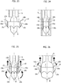
- Figure 22a is exemplary of embodiments where the end portions 10b, 10c are extendable to an insertion condition of the prosthesis wherein the end portions 10b, 10c are aligned with the web portion 10a by being spread apart to extend axially away from the web portion 10a as depicted in broken lines in figure 22a to extend axially and away from the annular structure 2, 3.
- the end portions 10b, 10c are then re-closable (e.g. elastically) to an anchoring condition (depicted in full lines), wherein the end portions 10b, 10c are bent or folded towards the web portion 10a (and thus at an angle therewith) radially outwardly from the annular structure to provide anchoring of the prosthesis proximally and distally of the annulus A (schematically represented in chain lines).
- Figure 22b is representative of exemplary embodiments wherein the end portion 10b may be again extendable to an insertion condition of the prosthesis wherein the end portion 10b is spread apart to extend axially away from the web portion 10a and is thus aligned with the web portion 10a.
- alignment of the end portion 10c with the web portion 10a to an insertion condition of the prosthesis is achieved by the end portion being fully folded towards (e.g. urged against) the web portion 10a.
- the end portions 10b, 10c may then move (e.g.
- the deployment mechanism exemplified in figure 22b for the end portion 10c may be applied (also) to the end portion 10b.
- Figures 22a and 22b describe two exemplary ways of having end portions 10b, 10c located at axially opposed sides of the web portion 10a, with the end portions 10b, 10c that admit (that is, are adapted to assume e.g. by moving to and/or being brought to):
- Figure 22a is exemplary of anchoring members 10 having one or both (i.e. at least one) end portions 10b, 10c with:
- Figure 22b is exemplary of anchoring members 10 having (at least) one end portion - e.g. end portion 10c - with:
- Both mechanisms exemplified in figures 22a and figure 22b may be applied to anchoring members 100 obtained from ring or loop body of a wire-like material as discussed in the foregoing and to blade-like anchoring members produced as cutouts from a sheet of - e.g. (super)elastic - material.
- the anchoring members 10 may be formed in such a way that the anchoring condition (i.e. the condition wherein the end portions 10b, 10c are at an angle to the web portion 10a radially outwardly from the annular structure 2,3) is an unconstrained "rest" condition to which the anchoring members 10 elastically return in the absence of deformation stress applied to the anchoring members.
- the anchoring condition i.e. the condition wherein the end portions 10b, 10c are at an angle to the web portion 10a radially outwardly from the annular structure 2,3
- the anchoring condition i.e. the condition wherein the end portions 10b, 10c are at an angle to the web portion 10a radially outwardly from the annular structure 2,3
- the anchoring condition i.e. the condition wherein the end portions 10b, 10c are at an angle to the web portion 10a radially outwardly from the annular structure 2,3
- the intermediate portions 10a includes two rectilinear branches of the intermediate portion of the elongated ring-shaped body constituting the anchoring member 10.
- Figures 11 and 12 represent other possible exemplary embodiments of the central web portion 10a.
- the covering 210 (or the portion of the covering 210) arranged on the outer side of the annular structure 2,3 acts as a separation member between the armature 2 and the anchoring members 10 coupled therewith with the portions 10a, 10b, and 10c arranged to lie radially outwardly of the covering 210.
- the anchoring members 10 may be coupled to the annular portion 2, 3 by various types of links, optionally flexible.
- the central portion 10a of the anchoring members 10 may be "stitched" to the (e.g. textile) covering 210 of the armature 2.
- the central portion 10a of the anchoring members 10 may be provided with holes 100 for possible use in coupling the relative anchoring member 10 to the annular structure 2, 3 e.g. by using a wire member (e.g. a suture) through the (e.g. textile) covering 210 of the armature 2 (see figure 1 ).
- a wire member e.g. a suture
- the (e.g. textile) covering 210 of the armature 2 see figure 1 .
- Such coupling by stitches may permit the anchoring members 10 to be adjustably coupled to the structure 2, 3.
- the physician may moderately adjust the location of the members 10 with respect to the structure before securing suture.
- No such holes may be provided in various embodiments as exemplified in figure 11 , wherein the branches of the intermediate web portion 10a are provided with enlarged zones 102 which may be exploited e.g. for stitching the anchoring member 10 to the covering 210 of the armature 2.
- Holes 100 adapted for passing suture for adjustably coupling the anchoring member 10 to the covering 210 of the armature 2, 3 are exemplified also in the embodiment of figure 12 : there the intermediate portion 10a is simply comprised of the rectilinear bar or "link" connecting to end portions 10b, 10c which may possibly have the shape as depicted in figure 12 .
- a collapsible valve prosthesis 1 as exemplified herein can be deployed at the implant site (e.g. mitral) by resorting to sutureless (e.g. thoracic microsurgery or percutaneous) techniques.
- implant site e.g. mitral
- sutureless e.g. thoracic microsurgery or percutaneous
- delivery and deployment may be by means of delivery system including an expandable member such as an expandable balloon B and a sliding sleeve delivery feature S.
- delivery system may be configured for a single access root, e.g. atrial as schematically exemplified, or for different access roots e.g. ventricular (transapical).
- the anchoring members 10 may be self-expandable (e.g. include shape-memory material such as Ni-Ti or Nitinol, harmonic steel, polymers) so that in the absence of applied deformation stress the end portions 10b, 10c will elastically assume the anchoring condition.
- shape-memory material such as Ni-Ti or Nitinol, harmonic steel, polymers
- the annular structure 2, 3 may include materials (e.g. stainless steel, chrome-cobalt alloys, titanium) making it expandable to a radially expanded implantation condition from a radially contracted insertion condition under the action of an expansion member e.g. be balloon-expandable.
- materials e.g. stainless steel, chrome-cobalt alloys, titanium
- annular structure 2, 3 may be self-expandable.
- Figure 23 schematically represents a collapsible valve prosthesis 1 including an annular structure 2, 3 in a radially expanded condition having the anchoring members 10 arranged therearound in their C-shaped or G-shaped "closed" condition.
- the (unexpanded) balloon B may be inserted into the axial lumen of the annular structure 2, 3 and the annular structure 2, 3 is then "crimped" (i.e. radially contracted, by known means) onto the balloon B, while the anchoring members 10 are brought to the insertion condition wherein the end portions 10b, 10c are aligned with the web portion 10a.
- this may occur e.g. by "stretching" the end portions 10b, 10c to their extended condition wherein the end portions 10b, 10c are spread apart from the web portion 10a and extend substantially axially of the annular structure 2, 3 outwardly of the axially opposed ends of the structure 2, 3.
- the end portions 10b may again be stretched to their extended condition wherein they are spread apart from the web portion 10a, while the end portions 10c may be bent inwardly against the web portion 10a, so that both end portions 10b and 10c extend substantially axially of the annular structure 2.
- the sleeve feature S may then be located (e.g. by axial sliding) around the prosthesis 1 in such a way to constrict and thus retain the anchoring members 10 to the insertion condition with the end portions 10b, 10c of the anchoring members 10 aligned with the web portion 10a.
- the sleeve feature S may also similarly constrict and retain to the radially contracted condition the structure 2, 3 in case this is self-expandable.
- the arrangement of parts just described may correspond to various embodiments of an implantation kit permitting the prosthesis 2 to be advanced to the implantation location (e.g. via a single access route, e.g. atrial).
- the sleeve S may be retracted proximally to uncover the end portions 10c of the anchoring members (see e.g. figure 25 ). Being no longer radially constricted by the sleeve S, the end portions 10c (herein assumed to be elastic) will return to their original unconstricted condition wherein they are at an angle (see e.g. ⁇ , beta in figure 6b ) to the web portion 10a.
- the end portions 10c will rotate towards ( figure 22a ) or away ( figure 22b ) the web portion 10a to reach a configuration as exemplified previously wherein the end portions 10c "embrace” or “grasp” one of the sides (distal, namely outflow in the exemplary mitral environment considered herein) of the native valve site.
- Axial proximal retraction of the sleeve S may continue thus releasing the opposed end portions 10b of the anchoring members 10.
- the end portions 10b (herein assumed to be elastic) will return to their original unconstricted condition wherein they are at an angle (see e.g. ⁇ , alpha in figure 5b ) to the web portion 10a. That is, the end portions 10c will rotate with respect to the web portion 10a to reach a configuration wherein the end portions 10b complete the C-shape or G-shape (i.e. channel-like) of the anchoring members 10 while, by actuating the expandable balloon B, the practitioner will be in a position to produce the radial expansion of the annular structure carrying the valve leaflet or leaflets 3.
- the end portions 10b will abut against the (herein "inflow") side of the native annulus by completing engagement of the natural valve site to provide secure anchoring of the prosthesis 1 at the desired implantation site without exerting undue radial expansion force of the annulus site.
- balloon expandability of the annular structure 2, 3 may permit to coordinate radial expansion from the radially contracted crimped condition, while releasing the prosthesis 1 by deflating the balloon B (only) when the desired implant condition is achieved.
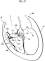
- Figure 27 is a schematic representation of the left ventricle LV of a human heart with a mitral valve MV controlling the flow of blood from the left atrium LA into the left ventricle LV and an aortic valve AV controlling the flow of blood pumped from the left ventricle VL into the aorta AA.
- FIG. 27 is a schematic representation of the application of an embodiment for Mitral Valve Replacement (MVR) with at least substantial conservation of the structures of the native mitral valve MV, namely the mitral valve leaflets VL and chordae tendineae CT.
- MVR Mitral Valve Replacement
- the prosthesis 1 will have a final geometrical shape which will generally approximate the physiological shape and dimension of the mitral annulus.
- the annular portion 2, 3 will define a blood flow lumen having an inflow (i.e. atrial) side and an outflow (i.e. ventricular) side, with the armature 2 supporting the prosthetic valve leaflet or leaflets 3a, 3b, 3c in the blood flow lumen, while the anchoring members 10 will couple with the natural valve site by capturing the native tissues, primarily the natural valve leaflets VL without exerting undue radial expansion force of the annulus site.
- chordae tendineae CT (if present, i.e. if extant and not removed) will still co-operate in retaining the prosthesis 1 at the implantation site resisting displacement by ventricular-to-atrial blood back pressure (e.g. during systole): this may be due to the chordae tendineae CT being "grasped" at their ends by the end portions 10c and/or due to the chordae tendineae CT being still connected to the natural valve leaflets VL which are in turn "grasped" by the end portions 10c.
Claims (18)
- Prothèse valvulaire (1) pour être placée au niveau d'un anneau de valvule (A), la prothèse (1) comportant :- une structure annulaire (2, 3) comportant une armature (2) et un ensemble de feuillets (3), la structure annulaire (2, 3) ayant une lumière axiale d'écoulement sanguin et au moins un feuillet de valvule (3a, 3b, 3c) mobile sous l'effet du sang entre une position ouverte et une position fermée pour permettre et empêcher, respectivement, l'écoulement sanguin à travers ladite lumière axiale d'écoulement sanguin, et- une pluralité d'éléments d'ancrage (10) fixés autour de la structure annulaire (2), les éléments d'ancrage (10) comportant :- une partie de bande (10a) couplée à la structure annulaire (2, 3) et s'étendant axialement vers celle-ci, et- deux parties d'extrémité (10b, 10c) sur des côtés axialement opposés de la partie de bande (10a), les parties d'extrémité (10b, 10c) adoptant :- a) un état d'insertion pour l'insertion de la prothèse (1), dans lequel les parties d'extrémité (10b, 10c) sont alignées avec la partie de bande (10a) et s'étendent axialement par rapport à la structure annulaire (2, 3) ;- b) un état d'ancrage pour l'ancrage de la prothèse (1), dans lequel les parties d'extrémité (10b, 10c) s'étendent selon un angle (α, β) par rapport à la partie de bande (10a) radialement vers l'extérieur de la structure annulaire (2) pour assurer l'ancrage de la prothèse de manière proximale et distale, respectivement, par rapport à l'anneau (A),- un revêtement en forme de feuille (210) sur le côté externe de la structure annulaire (2, 3),la prothèse valvulaire (1) étant caractérisée en ce que les éléments d'ancrage (10) ont leurs parties de bande (10a) et d'extrémité (10b, 10c) radialement vers l'extérieur du revêtement en forme de feuille (210), moyennant quoi le revêtement en forme de feuille (210) sert d'élément de séparation entre l'armature (2) et les éléments d'ancrage (10).
- Prothèse valvulaire (1) de la revendication 1, comportant des éléments d'ancrage (10) ayant au moins une partie d'extrémité (10b, 10c) avec un état d'insertion dans lequel l'au moins une partie d'extrémité (10b, 10c) est écartée de la partie de bande (10a) et s'étend axialement à partir de la structure annulaire (2, 3) et un état d'ancrage dans lequel l'au moins une partie d'extrémité (10b, 10c) est pliée vers la partie de bande (10a) selon un angle par rapport à celle-ci radialement vers l'extérieur de la structure annulaire (2, 3).
- Prothèse valvulaire (1) de la revendication 1 ou 2, comportant des éléments d'ancrage (10) ayant au moins une partie d'extrémité (10c) avec un état d'insertion dans lequel l'au moins une partie d'extrémité (10c) est pliée contre la partie de bande (10a) et s'étend axialement par rapport à la structure annulaire (2, 3) et un état d'ancrage dans lequel l'au moins une partie d'extrémité (10c) est déployée loin de la partie de bande (10a) selon un angle par rapport à celle-ci radialement vers l'extérieur de la structure annulaire (2, 3).
- Prothèse valvulaire (1) de l'une des revendications précédentes, comportant des éléments d'ancrage (10) couplés de manière ajustable à la structure annulaire (2, 3).
- Prothèse valvulaire (1) de l'une des revendications précédentes, comportant des éléments d'ancrage (10) couplés à la structure annulaire (2, 3) par des liaisons flexibles.
- Prothèse valvulaire (1) des revendications 1 et 5, dans laquelle les liaisons flexibles comportent des points de suture à travers le revêtement en forme de feuille (210).
- Prothèse valvulaire (1) de l'une des revendications précédentes, dans laquelle les éléments d'ancrage (10) comportent un matériau élastique, de préférence superélastique.
- Prothèse valvulaire (1) de l'une des revendications précédentes, comportant des éléments d'ancrage (10) comportant l'un parmi :- un corps en forme de bague allongée ayant des parties en boucle et une partie intermédiaire entre les parties en boucle formant les parties d'extrémité (10b, 10c) et la partie de bande (10a), respectivement, de l'élément d'ancrage (10),- un corps en forme de lame.
- Prothèse valvulaire (1) de l'une des revendications précédentes, comportant des éléments d'ancrage (10) répartis avec un espacement uniforme autour de la structure annulaire (2, 3).
- Prothèse valvulaire (1) de l'une des revendications 1 à 8, comportant des éléments d'ancrage (10) répartis avec un espacement non uniforme autour de la structure annulaire (2, 3).
- Prothèse valvulaire (1) de l'une des revendications précédentes, comportant un ensemble d'éléments d'ancrage identiques (10).
- Prothèse valvulaire (1) de l'une des revendications 1 à 10, comportant des éléments d'ancrage (10) ayant différentes tailles et/ou formes à différents endroits autour de la structure annulaire (2, 3).
- Prothèse valvulaire (1) de l'une des revendications précédentes, dans laquelle la structure annulaire (2, 3) a une forme choisie parmi une forme circulaire, une forme non circulaire et une forme en D.
- Prothèse valvulaire (1) de l'une des revendications précédentes, comportant des éléments d'ancrage (10) avec des parties d'extrémité (10b, 10c) qui adoptent élastiquement l'état d'ancrage en l'absence de contrainte de déformation appliquée.
- Prothèse valvulaire (1) de l'une des revendications précédentes, dans laquelle la structure annulaire (2, 3) peut se contracter vers un état d'insertion radialement contracté et peut se dilater vers un état d'implantation radialement dilaté.
- Prothèse valvulaire (1) de la revendication 15, dans laquelle la structure annulaire (2, 3) est auto-dilatable vers un état d'implantation radialement dilaté.
- Prothèse valvulaire (1) de la revendication 14 ou 15, dans laquelle la structure annulaire (2, 3) peut se dilater vers un état d'implantation radialement dilaté sous l'effet d'un élément de dilatation (B).
- Kit de pose pour une prothèse valvulaire (1) comportant :- un élément pouvant se dilater non dilaté (B) portant une valvule selon l'une des revendications 1 à 17 radialement contractée sur celui-ci,- un élément de gaine (S) agencé autour de l'élément pouvant se dilater (B) et resserrant radialement vers l'état d'insertion les parties d'extrémité (10b, 10c) des éléments d'ancrage (10) de la prothèse valvulaire (1) radialement contractée sur l'élément pouvant se dilater (B),- l'élément de gaine (S) pouvant coulisser sur l'élément pouvant se dilater (B) pour désengager séquentiellement les parties d'extrémité (10b, 10c) des éléments d'ancrage afin de permettre aux parties d'extrémité (10b, 10c) d'adopter l'état d'ancrage avec la structure annulaire (2) radialement dilatée en raison de la dilatation de l'élément pouvant se dilater (B).
Priority Applications (3)
| Application Number | Priority Date | Filing Date | Title |
|---|---|---|---|
| EP12425139.8A EP2695586B1 (fr) | 2012-08-10 | 2012-08-10 | Prothèse de valvule et kit |
| ES12425139T ES2735536T3 (es) | 2012-08-10 | 2012-08-10 | Una prótesis de válvula y un kit |
| US13/962,789 US9186249B2 (en) | 2012-08-10 | 2013-08-08 | Valve prosthesis and kit |
Applications Claiming Priority (1)
| Application Number | Priority Date | Filing Date | Title |
|---|---|---|---|
| EP12425139.8A EP2695586B1 (fr) | 2012-08-10 | 2012-08-10 | Prothèse de valvule et kit |
Publications (2)
| Publication Number | Publication Date |
|---|---|
| EP2695586A1 EP2695586A1 (fr) | 2014-02-12 |
| EP2695586B1 true EP2695586B1 (fr) | 2019-05-08 |
Family
ID=47080398
Family Applications (1)
| Application Number | Title | Priority Date | Filing Date |
|---|---|---|---|
| EP12425139.8A Active EP2695586B1 (fr) | 2012-08-10 | 2012-08-10 | Prothèse de valvule et kit |
Country Status (3)
| Country | Link |
|---|---|
| US (1) | US9186249B2 (fr) |
| EP (1) | EP2695586B1 (fr) |
| ES (1) | ES2735536T3 (fr) |
Cited By (13)
| Publication number | Priority date | Publication date | Assignee | Title |
|---|---|---|---|---|
| US10856984B2 (en) | 2017-08-25 | 2020-12-08 | Neovasc Tiara Inc. | Sequentially deployed transcatheter mitral valve prosthesis |
| US10940001B2 (en) | 2012-05-30 | 2021-03-09 | Neovasc Tiara Inc. | Methods and apparatus for loading a prosthesis onto a delivery system |
| US11311376B2 (en) | 2019-06-20 | 2022-04-26 | Neovase Tiara Inc. | Low profile prosthetic mitral valve |
| US11357622B2 (en) | 2016-01-29 | 2022-06-14 | Neovase Tiara Inc. | Prosthetic valve for avoiding obstruction of outflow |
| US11389291B2 (en) | 2013-04-04 | 2022-07-19 | Neovase Tiara Inc. | Methods and apparatus for delivering a prosthetic valve to a beating heart |
| US11413139B2 (en) | 2011-11-23 | 2022-08-16 | Neovasc Tiara Inc. | Sequentially deployed transcatheter mitral valve prosthesis |
| US11419720B2 (en) | 2010-05-05 | 2022-08-23 | Neovasc Tiara Inc. | Transcatheter mitral valve prosthesis |
| US11464631B2 (en) | 2016-11-21 | 2022-10-11 | Neovasc Tiara Inc. | Methods and systems for rapid retraction of a transcatheter heart valve delivery system |
| US11491006B2 (en) | 2019-04-10 | 2022-11-08 | Neovasc Tiara Inc. | Prosthetic valve with natural blood flow |
| US11497602B2 (en) | 2012-02-14 | 2022-11-15 | Neovasc Tiara Inc. | Methods and apparatus for engaging a valve prosthesis with tissue |
| US11602429B2 (en) | 2019-04-01 | 2023-03-14 | Neovasc Tiara Inc. | Controllably deployable prosthetic valve |
| US11737872B2 (en) | 2018-11-08 | 2023-08-29 | Neovasc Tiara Inc. | Ventricular deployment of a transcatheter mitral valve prosthesis |
| US11779742B2 (en) | 2019-05-20 | 2023-10-10 | Neovasc Tiara Inc. | Introducer with hemostasis mechanism |
Families Citing this family (94)
| Publication number | Priority date | Publication date | Assignee | Title |
|---|---|---|---|---|
| WO2007058857A2 (fr) | 2005-11-10 | 2007-05-24 | Arshad Quadri | Stent de raccordement de prothese vasculaire, a deploiement automatique, pouvant etre deploye par ballonnet |
| SE530568C2 (sv) * | 2006-11-13 | 2008-07-08 | Medtentia Ab | Anordning och metod för förbättring av funktionen hos en hjärtklaff |
| US9532868B2 (en) | 2007-09-28 | 2017-01-03 | St. Jude Medical, Inc. | Collapsible-expandable prosthetic heart valves with structures for clamping native tissue |
| US8652202B2 (en) | 2008-08-22 | 2014-02-18 | Edwards Lifesciences Corporation | Prosthetic heart valve and delivery apparatus |
| EP3753534A1 (fr) | 2008-09-29 | 2020-12-23 | Edwards Lifesciences CardiAQ LLC | Valvule cardiaque |
| EP3708123A1 (fr) | 2009-03-30 | 2020-09-16 | JC Medical, Inc. | Prothèses valvulaires sans suture, dispositifs et procédés d'administration |
| CA2961053C (fr) | 2009-04-15 | 2019-04-30 | Edwards Lifesciences Cardiaq Llc | Implant vasculaire et systeme d'introduction |
| US20110313515A1 (en) | 2010-06-21 | 2011-12-22 | Arshad Quadri | Replacement heart valve |
| US9730790B2 (en) | 2009-09-29 | 2017-08-15 | Edwards Lifesciences Cardiaq Llc | Replacement valve and method |
| US8449599B2 (en) | 2009-12-04 | 2013-05-28 | Edwards Lifesciences Corporation | Prosthetic valve for replacing mitral valve |
| CA2822381C (fr) | 2010-12-23 | 2019-04-02 | Foundry Newco Xii, Inc. | Systeme de reparation et remplacement de valvule mitrale |
| WO2012127309A1 (fr) * | 2011-03-21 | 2012-09-27 | Ontorfano Matteo | Appareil pour valvule à disques et procédé de traitement du dysfonctionnement de la valvule |
| WO2012177942A2 (fr) | 2011-06-21 | 2012-12-27 | Hanson Gifford, Iii | Dispositifs de valvule cardiaque prosthétiques et systèmes et procédés associés |
| US11202704B2 (en) | 2011-10-19 | 2021-12-21 | Twelve, Inc. | Prosthetic heart valve devices, prosthetic mitral valves and associated systems and methods |
| JP6133309B2 (ja) | 2011-10-19 | 2017-05-24 | トゥエルヴ, インコーポレイテッド | 人工心臓弁デバイス |
| US9039757B2 (en) | 2011-10-19 | 2015-05-26 | Twelve, Inc. | Prosthetic heart valve devices, prosthetic mitral valves and associated systems and methods |
| EP2750630B1 (fr) | 2011-10-19 | 2021-06-30 | Twelve, Inc. | Dispositif de remplacement de valvule cardiaque |
| EP2886083B1 (fr) | 2012-03-23 | 2018-05-16 | Sorin Group Italia S.r.l. | Prothèse de valvule repliable |
| US9232995B2 (en) | 2013-01-08 | 2016-01-12 | Medtronic, Inc. | Valve prosthesis and method for delivery |
| US9730791B2 (en) | 2013-03-14 | 2017-08-15 | Edwards Lifesciences Cardiaq Llc | Prosthesis for atraumatically grasping intralumenal tissue and methods of delivery |
| US11406497B2 (en) | 2013-03-14 | 2022-08-09 | Jc Medical, Inc. | Heart valve prosthesis |
| US20140277427A1 (en) | 2013-03-14 | 2014-09-18 | Cardiaq Valve Technologies, Inc. | Prosthesis for atraumatically grasping intralumenal tissue and methods of delivery |
| US9681951B2 (en) | 2013-03-14 | 2017-06-20 | Edwards Lifesciences Cardiaq Llc | Prosthesis with outer skirt and anchors |
| CN105163687B (zh) | 2013-03-14 | 2019-08-13 | 心肺医疗股份有限公司 | 栓子保护装置和使用方法 |
| US11259923B2 (en) | 2013-03-14 | 2022-03-01 | Jc Medical, Inc. | Methods and devices for delivery of a prosthetic valve |
| AU2014268631B2 (en) | 2013-05-20 | 2019-08-01 | Twelve, Inc. | Implantable heart valve devices, mitral valve repair devices and associated systems and methods |
| EP2835112B1 (fr) | 2013-08-08 | 2021-01-27 | Sorin Group Italia S.r.l. | Prothèse de valvule cardiaque |
| US9839511B2 (en) * | 2013-10-05 | 2017-12-12 | Sino Medical Sciences Technology Inc. | Device and method for mitral valve regurgitation treatment |
| WO2015126711A1 (fr) * | 2014-02-18 | 2015-08-27 | St. Jude Medical, Cardiology Division, Inc. | Patins courbés, et ensembles valves correspondants pour protection de fuite paravalvulaire |
| EP3107497B1 (fr) | 2014-02-21 | 2020-07-22 | Edwards Lifesciences CardiAQ LLC | Dispositif d'acheminement pour le déploiement maîtrisé d'une de valvule de substitution |
| US10245141B2 (en) | 2014-05-14 | 2019-04-02 | Sorin Group Italia S.R.L. | Implant device and implantation kit |
| CA3161000A1 (fr) | 2014-05-19 | 2015-11-26 | Edwards Lifesciences Cardiaq Llc | Valvule mitrale de remplacement ayant un rabat annulaire |
| US9532870B2 (en) * | 2014-06-06 | 2017-01-03 | Edwards Lifesciences Corporation | Prosthetic valve for replacing a mitral valve |
| JP6700278B2 (ja) | 2014-12-04 | 2020-05-27 | エドワーズ ライフサイエンシーズ コーポレイションEdwards Lifesciences Corporation | 心臓弁を修復するための経皮的クリップ |
| EP3028668A1 (fr) * | 2014-12-05 | 2016-06-08 | Nvt Ag | Système de valvule cardiaque prothétique et système d'administration à cet effet |
| US10441416B2 (en) | 2015-04-21 | 2019-10-15 | Edwards Lifesciences Corporation | Percutaneous mitral valve replacement device |
| US10376363B2 (en) | 2015-04-30 | 2019-08-13 | Edwards Lifesciences Cardiaq Llc | Replacement mitral valve, delivery system for replacement mitral valve and methods of use |
| EP3294219B1 (fr) | 2015-05-14 | 2020-05-13 | Edwards Lifesciences Corporation | Dispositifs d'étanchéité de valves cardiaques et leurs dispositifs de pose |
| US10226335B2 (en) | 2015-06-22 | 2019-03-12 | Edwards Lifesciences Cardiaq Llc | Actively controllable heart valve implant and method of controlling same |
| US10092400B2 (en) | 2015-06-23 | 2018-10-09 | Edwards Lifesciences Cardiaq Llc | Systems and methods for anchoring and sealing a prosthetic heart valve |
| JP7111610B2 (ja) | 2015-08-21 | 2022-08-02 | トゥエルヴ, インコーポレイテッド | 埋込可能な心臓弁デバイス、僧帽弁修復デバイス、ならびに関連するシステム及び方法 |
| US10117744B2 (en) | 2015-08-26 | 2018-11-06 | Edwards Lifesciences Cardiaq Llc | Replacement heart valves and methods of delivery |
| US10575951B2 (en) | 2015-08-26 | 2020-03-03 | Edwards Lifesciences Cardiaq Llc | Delivery device and methods of use for transapical delivery of replacement mitral valve |
| US10350066B2 (en) | 2015-08-28 | 2019-07-16 | Edwards Lifesciences Cardiaq Llc | Steerable delivery system for replacement mitral valve and methods of use |
| US10456243B2 (en) * | 2015-10-09 | 2019-10-29 | Medtronic Vascular, Inc. | Heart valves prostheses and methods for percutaneous heart valve replacement |
| US10321992B2 (en) | 2016-02-01 | 2019-06-18 | Medtronic, Inc. | Heart valve prostheses having multiple support arms and methods for percutaneous heart valve replacement |
| US11219746B2 (en) | 2016-03-21 | 2022-01-11 | Edwards Lifesciences Corporation | Multi-direction steerable handles for steering catheters |
| US10835714B2 (en) | 2016-03-21 | 2020-11-17 | Edwards Lifesciences Corporation | Multi-direction steerable handles for steering catheters |
| US10799675B2 (en) | 2016-03-21 | 2020-10-13 | Edwards Lifesciences Corporation | Cam controlled multi-direction steerable handles |
| USD815744S1 (en) | 2016-04-28 | 2018-04-17 | Edwards Lifesciences Cardiaq Llc | Valve frame for a delivery system |
| US10973638B2 (en) | 2016-07-07 | 2021-04-13 | Edwards Lifesciences Corporation | Device and method for treating vascular insufficiency |
| US10350062B2 (en) | 2016-07-21 | 2019-07-16 | Edwards Lifesciences Corporation | Replacement heart valve prosthesis |
| CA3033666A1 (fr) | 2016-08-19 | 2018-02-22 | Edwards Lifesciences Corporation | Systeme de pose maniable pour valvule mitrale de remplacement et procedes d'utilisation |
| US10639143B2 (en) | 2016-08-26 | 2020-05-05 | Edwards Lifesciences Corporation | Multi-portion replacement heart valve prosthesis |
| EP3531977A1 (fr) * | 2016-10-28 | 2019-09-04 | St. Jude Medical, Cardiology Division, Inc. | Valvule mitrale prothétique |
| US10758348B2 (en) | 2016-11-02 | 2020-09-01 | Edwards Lifesciences Corporation | Supra and sub-annular mitral valve delivery system |
| US10653862B2 (en) | 2016-11-07 | 2020-05-19 | Edwards Lifesciences Corporation | Apparatus for the introduction and manipulation of multiple telescoping catheters |
| US10905554B2 (en) | 2017-01-05 | 2021-02-02 | Edwards Lifesciences Corporation | Heart valve coaptation device |
| US10433961B2 (en) | 2017-04-18 | 2019-10-08 | Twelve, Inc. | Delivery systems with tethers for prosthetic heart valve devices and associated methods |
| US11224511B2 (en) | 2017-04-18 | 2022-01-18 | Edwards Lifesciences Corporation | Heart valve sealing devices and delivery devices therefor |
| LT3682854T (lt) | 2017-04-18 | 2022-03-10 | Edwards Lifesciences Corporation | Širdies vožtuvo sandarinimo įrenginiai ir jų perdavimo įtaisai |
| US10702378B2 (en) | 2017-04-18 | 2020-07-07 | Twelve, Inc. | Prosthetic heart valve device and associated systems and methods |
| US10799312B2 (en) | 2017-04-28 | 2020-10-13 | Edwards Lifesciences Corporation | Medical device stabilizing apparatus and method of use |
| US10959846B2 (en) | 2017-05-10 | 2021-03-30 | Edwards Lifesciences Corporation | Mitral valve spacer device |
| US10792151B2 (en) | 2017-05-11 | 2020-10-06 | Twelve, Inc. | Delivery systems for delivering prosthetic heart valve devices and associated methods |
| US10709591B2 (en) | 2017-06-06 | 2020-07-14 | Twelve, Inc. | Crimping device and method for loading stents and prosthetic heart valves |
| US10786352B2 (en) | 2017-07-06 | 2020-09-29 | Twelve, Inc. | Prosthetic heart valve devices and associated systems and methods |
| US11123186B2 (en) | 2017-07-06 | 2021-09-21 | Edwards Lifesciences Corporation | Steerable delivery system and components |
| US10729541B2 (en) | 2017-07-06 | 2020-08-04 | Twelve, Inc. | Prosthetic heart valve devices and associated systems and methods |
| US11051940B2 (en) | 2017-09-07 | 2021-07-06 | Edwards Lifesciences Corporation | Prosthetic spacer device for heart valve |
| US11065117B2 (en) | 2017-09-08 | 2021-07-20 | Edwards Lifesciences Corporation | Axisymmetric adjustable device for treating mitral regurgitation |
| US11110251B2 (en) | 2017-09-19 | 2021-09-07 | Edwards Lifesciences Corporation | Multi-direction steerable handles for steering catheters |
| AU2019205321A1 (en) | 2018-01-07 | 2020-07-23 | Jc Medical, Inc. | Prosthetic heart valve delivery system |
| CN210727936U (zh) | 2018-01-07 | 2020-06-12 | 苏州杰成医疗科技有限公司 | 瓣膜假体递送装置 |
| MX2020005397A (es) | 2018-01-09 | 2020-08-17 | Edwards Lifesciences Corp | Dispositivos y procedimientos de reparacion de valvulas nativas. |
| US10123873B1 (en) | 2018-01-09 | 2018-11-13 | Edwards Lifesciences Corporation | Native valve repair devices and procedures |
| US10136993B1 (en) | 2018-01-09 | 2018-11-27 | Edwards Lifesciences Corporation | Native valve repair devices and procedures |
| US10105222B1 (en) | 2018-01-09 | 2018-10-23 | Edwards Lifesciences Corporation | Native valve repair devices and procedures |
| US10245144B1 (en) | 2018-01-09 | 2019-04-02 | Edwards Lifesciences Corporation | Native valve repair devices and procedures |
| US10973639B2 (en) | 2018-01-09 | 2021-04-13 | Edwards Lifesciences Corporation | Native valve repair devices and procedures |
| US10159570B1 (en) | 2018-01-09 | 2018-12-25 | Edwards Lifesciences Corporation | Native valve repair devices and procedures |
| US10111751B1 (en) | 2018-01-09 | 2018-10-30 | Edwards Lifesciences Corporation | Native valve repair devices and procedures |
| US10238493B1 (en) | 2018-01-09 | 2019-03-26 | Edwards Lifesciences Corporation | Native valve repair devices and procedures |
| US10076415B1 (en) | 2018-01-09 | 2018-09-18 | Edwards Lifesciences Corporation | Native valve repair devices and procedures |
| US10231837B1 (en) | 2018-01-09 | 2019-03-19 | Edwards Lifesciences Corporation | Native valve repair devices and procedures |
| EP3720390B1 (fr) | 2018-01-25 | 2024-05-01 | Edwards Lifesciences Corporation | Système de distribution pour recapture de valvule de remplacement assistée et post-déploiement de repositionnement |
| US11051934B2 (en) | 2018-02-28 | 2021-07-06 | Edwards Lifesciences Corporation | Prosthetic mitral valve with improved anchors and seal |
| US11389297B2 (en) | 2018-04-12 | 2022-07-19 | Edwards Lifesciences Corporation | Mitral valve spacer device |
| US11207181B2 (en) | 2018-04-18 | 2021-12-28 | Edwards Lifesciences Corporation | Heart valve sealing devices and delivery devices therefor |
| WO2019224577A1 (fr) | 2018-05-23 | 2019-11-28 | Sorin Group Italia S.R.L. | Prothèse de valvule cardiaque |
| US10945844B2 (en) | 2018-10-10 | 2021-03-16 | Edwards Lifesciences Corporation | Heart valve sealing devices and delivery devices therefor |
| BR122021018576A2 (pt) | 2019-02-14 | 2021-10-13 | Edwards Lifesciences Corporation | Dispositivo de reparo de válvula para reparar uma válvula nativa de um paciente e sistema de reparo de válvula |
| US11452599B2 (en) | 2019-05-02 | 2022-09-27 | Twelve, Inc. | Fluid diversion devices for hydraulic delivery systems and associated methods |
| EP3965696A4 (fr) * | 2019-05-09 | 2023-02-08 | Caisson Interventional, LLC | Techniques de pose inversée de valvules cardiaques prothétiques |
Citations (1)
| Publication number | Priority date | Publication date | Assignee | Title |
|---|---|---|---|---|
| EP2886083A1 (fr) * | 2012-03-23 | 2015-06-24 | Sorin Group Italia S.r.l. | Prothèse de valvule repliable |
Family Cites Families (95)
| Publication number | Priority date | Publication date | Assignee | Title |
|---|---|---|---|---|
| IT1159433B (it) | 1983-07-25 | 1987-02-25 | Sorin Biomedica Spa | Procedimento ed apparecchiatura per la fabbricazione di lembi valvolari per protesi valvolari cardiache e protesi valvolare cardiaca provvista di tali lembi |
| IT1208326B (it) | 1984-03-16 | 1989-06-12 | Sorin Biomedica Spa | Protesi valvolare cardiaca provvista di lembi valvolari di tessuto biologico |
| IT1245750B (it) | 1991-05-24 | 1994-10-14 | Sorin Biomedica Emodialisi S R | Protesi valvolare cardiaca, particolarmente per sostituzione della valvola aortica |
| US5855601A (en) | 1996-06-21 | 1999-01-05 | The Trustees Of Columbia University In The City Of New York | Artificial heart valve and method and device for implanting the same |
| EP0850607A1 (fr) | 1996-12-31 | 1998-07-01 | Cordis Corporation | Prothèse de valve pour implantation dans des canaux corporels |
| FR2768324B1 (fr) | 1997-09-12 | 1999-12-10 | Jacques Seguin | Instrument chirurgical permettant, par voie percutanee, de fixer l'une a l'autre deux zones de tissu mou, normalement mutuellement distantes |
| ATE449581T1 (de) | 1997-12-29 | 2009-12-15 | The Cleveland Clinic Foundation | System zur minimalinvasiven einführung einer herzklappen- bioprothese |
| US6530952B2 (en) | 1997-12-29 | 2003-03-11 | The Cleveland Clinic Foundation | Bioprosthetic cardiovascular valve system |
| US6425916B1 (en) | 1999-02-10 | 2002-07-30 | Michi E. Garrison | Methods and devices for implanting cardiac valves |
| US6752813B2 (en) | 1999-04-09 | 2004-06-22 | Evalve, Inc. | Methods and devices for capturing and fixing leaflets in valve repair |
| EP2078498B1 (fr) | 1999-04-09 | 2010-12-22 | Evalve, Inc. | Appareil pour la réparation de valves cardiaques |
| US6287339B1 (en) | 1999-05-27 | 2001-09-11 | Sulzer Carbomedics Inc. | Sutureless heart valve prosthesis |
| US6312465B1 (en) | 1999-07-23 | 2001-11-06 | Sulzer Carbomedics Inc. | Heart valve prosthesis with a resiliently deformable retaining member |
| FR2800984B1 (fr) | 1999-11-17 | 2001-12-14 | Jacques Seguin | Dispositif de remplacement d'une valve cardiaque par voie percutanee |
| US7018406B2 (en) | 1999-11-17 | 2006-03-28 | Corevalve Sa | Prosthetic valve for transluminal delivery |
| US20070043435A1 (en) * | 1999-11-17 | 2007-02-22 | Jacques Seguin | Non-cylindrical prosthetic valve system for transluminal delivery |
| US8579966B2 (en) | 1999-11-17 | 2013-11-12 | Medtronic Corevalve Llc | Prosthetic valve for transluminal delivery |
| US6458153B1 (en) | 1999-12-31 | 2002-10-01 | Abps Venture One, Ltd. | Endoluminal cardiac and venous valve prostheses and methods of manufacture and delivery thereof |
| US6821297B2 (en) | 2000-02-02 | 2004-11-23 | Robert V. Snyders | Artificial heart valve, implantation instrument and method therefor |
| AU2001233227A1 (en) | 2000-02-02 | 2001-08-14 | Robert V. Snyders | Artificial heart valve |
| US7510572B2 (en) | 2000-09-12 | 2009-03-31 | Shlomo Gabbay | Implantation system for delivery of a heart valve prosthesis |
| US6974476B2 (en) | 2003-05-05 | 2005-12-13 | Rex Medical, L.P. | Percutaneous aortic valve |
| JP4328093B2 (ja) | 2000-11-21 | 2009-09-09 | レックス メディカル リミテッド パートナーシップ | 経皮的な大動脈弁 |
| US7556646B2 (en) * | 2001-09-13 | 2009-07-07 | Edwards Lifesciences Corporation | Methods and apparatuses for deploying minimally-invasive heart valves |
| FR2826863B1 (fr) | 2001-07-04 | 2003-09-26 | Jacques Seguin | Ensemble permettant la mise en place d'une valve prothetique dans un conduit corporel |
| EP2517674B1 (fr) * | 2002-08-15 | 2016-03-16 | Cook Medical Technologies LLC | Dispositif vasculaire implantable |
| JP2006501033A (ja) | 2002-10-01 | 2006-01-12 | アンプル メディカル, インコーポレイテッド | 心臓弁輪を再成形するためのデバイス、システムおよび方法 |
| AU2003277115A1 (en) | 2002-10-01 | 2004-04-23 | Ample Medical, Inc. | Device and method for repairing a native heart valve leaflet |
| US8551162B2 (en) | 2002-12-20 | 2013-10-08 | Medtronic, Inc. | Biologically implantable prosthesis |
| US20050137691A1 (en) | 2003-12-23 | 2005-06-23 | Sadra Medical | Two piece heart valve and anchor |
| US8182528B2 (en) | 2003-12-23 | 2012-05-22 | Sadra Medical, Inc. | Locking heart valve anchor |
| CN101947146B (zh) | 2003-12-23 | 2014-08-06 | 萨德拉医学公司 | 可再定位的心脏瓣膜 |
| EP3300692B1 (fr) | 2003-12-23 | 2019-06-19 | Boston Scientific Scimed, Inc. | Valvule cardiaque repositionnable |
| US7381219B2 (en) | 2003-12-23 | 2008-06-03 | Sadra Medical, Inc. | Low profile heart valve and delivery system |
| US20050137696A1 (en) | 2003-12-23 | 2005-06-23 | Sadra Medical | Apparatus and methods for protecting against embolization during endovascular heart valve replacement |
| US7780725B2 (en) | 2004-06-16 | 2010-08-24 | Sadra Medical, Inc. | Everting heart valve |
| US7311730B2 (en) * | 2004-02-13 | 2007-12-25 | Shlomo Gabbay | Support apparatus and heart valve prosthesis for sutureless implantation |
| FR2874812B1 (fr) | 2004-09-07 | 2007-06-15 | Perouse Soc Par Actions Simpli | Valve protheique interchangeable |
| FR2874813B1 (fr) | 2004-09-07 | 2007-06-22 | Perouse Soc Par Actions Simpli | Prothese valvulaire |
| US7758640B2 (en) | 2004-12-16 | 2010-07-20 | Valvexchange Inc. | Cardiovascular valve assembly |
| ITTO20050074A1 (it) | 2005-02-10 | 2006-08-11 | Sorin Biomedica Cardio Srl | Protesi valvola cardiaca |
| US20060195183A1 (en) | 2005-02-18 | 2006-08-31 | The Cleveland Clinic Foundation | Apparatus and methods for replacing a cardiac valve |
| US7717955B2 (en) | 2005-02-28 | 2010-05-18 | Medtronic, Inc. | Conformable prosthesis for implanting two-piece heart valves and methods for using them |
| EP1883375B1 (fr) | 2005-05-24 | 2016-12-07 | Edwards Lifesciences Corporation | Prothese de valvule cardiaque a deploiement rapide |
| US8876894B2 (en) | 2006-09-19 | 2014-11-04 | Medtronic Ventor Technologies Ltd. | Leaflet-sensitive valve fixation member |
| SE530568C2 (sv) | 2006-11-13 | 2008-07-08 | Medtentia Ab | Anordning och metod för förbättring av funktionen hos en hjärtklaff |
| JP5593545B2 (ja) | 2006-12-06 | 2014-09-24 | メドトロニック シーブイ ルクセンブルク エス.アー.エール.エル. | 弁輪に固定された自己拡張型弁の経心尖的送達のためのシステムおよび方法 |
| US8470024B2 (en) | 2006-12-19 | 2013-06-25 | Sorin Group Italia S.R.L. | Device for in situ positioning of cardiac valve prosthesis |
| EP1967164A3 (fr) | 2006-12-19 | 2009-01-28 | Sorin Biomedica Cardio S.R.L. | Instrument pour le déploiement in situ de prothèses valvulaires cardiaques |
| WO2008088835A1 (fr) | 2007-01-18 | 2008-07-24 | Valvexchange Inc. | Outils pour enlever et installer des valves cardiovasculaires échangeables |
| WO2008091515A2 (fr) | 2007-01-19 | 2008-07-31 | Medtronic, Inc. | Dispositifs de valve cardiaque à stent et procédés de remplacement d'une valve cardiaque auriculo-ventriculaire |
| WO2008089365A2 (fr) | 2007-01-19 | 2008-07-24 | The Cleveland Clinic Foundation | Méthode de mise en place d'une valve cardiovasculaire |
| US8070802B2 (en) | 2007-02-23 | 2011-12-06 | The Trustees Of The University Of Pennsylvania | Mitral valve system |
| US20080208328A1 (en) | 2007-02-23 | 2008-08-28 | Endovalve, Inc. | Systems and Methods For Placement of Valve Prosthesis System |
| US20080208327A1 (en) | 2007-02-27 | 2008-08-28 | Rowe Stanton J | Method and apparatus for replacing a prosthetic valve |
| ES2362950T3 (es) | 2007-09-07 | 2011-07-15 | Sorin Biomedica Cardio S.R.L. | Sistema de suministro lleno de líquido para el despliegue in situ de prótesis valvulares cardiacas. |
| EP2399527A1 (fr) | 2007-09-07 | 2011-12-28 | Sorin Biomedica Cardio S.r.l. | Systèmes de mise en place de soupapes prothétiques y compris par l'approche rétrograde/antérograde |
| WO2009045331A1 (fr) | 2007-09-28 | 2009-04-09 | St. Jude Medical, Inc. | Valvules cardiaques prothétiques repliables/déployables en deux temps et systèmes d'ancrage |
| US8715337B2 (en) | 2007-11-09 | 2014-05-06 | Cook Medical Technologies Llc | Aortic valve stent graft |
| EP2072027B1 (fr) | 2007-12-21 | 2020-06-17 | Medtentia International Ltd Oy | dispositif pré-annuloplastique et méthode |
| US20090276040A1 (en) | 2008-05-01 | 2009-11-05 | Edwards Lifesciences Corporation | Device and method for replacing mitral valve |
| US8323335B2 (en) | 2008-06-20 | 2012-12-04 | Edwards Lifesciences Corporation | Retaining mechanisms for prosthetic valves and methods for using |
| ES2792354T3 (es) | 2008-07-15 | 2020-11-11 | St Jude Medical Llc | Válvulas cardíacas protésicas plegables y reexpandibles, de anclaje axial, para diversos estados patológicos |
| US8287591B2 (en) | 2008-09-19 | 2012-10-16 | Edwards Lifesciences Corporation | Transformable annuloplasty ring configured to receive a percutaneous prosthetic heart valve implantation |
| EP3753534A1 (fr) * | 2008-09-29 | 2020-12-23 | Edwards Lifesciences CardiAQ LLC | Valvule cardiaque |
| JP5607639B2 (ja) | 2008-10-10 | 2014-10-15 | サドラ メディカル インコーポレイテッド | 医療用デバイス・システム |
| US10166014B2 (en) | 2008-11-21 | 2019-01-01 | Percutaneous Cardiovascular Solutions Pty Ltd | Heart valve prosthesis and method |
| US20100174363A1 (en) | 2009-01-07 | 2010-07-08 | Endovalve, Inc. | One Piece Prosthetic Valve Support Structure and Related Assemblies |
| EP3708123A1 (fr) | 2009-03-30 | 2020-09-16 | JC Medical, Inc. | Prothèses valvulaires sans suture, dispositifs et procédés d'administration |
| GB2469296B (en) | 2009-04-07 | 2011-03-09 | Cook Inc | Modular stent assembly |
| CA2961053C (fr) | 2009-04-15 | 2019-04-30 | Edwards Lifesciences Cardiaq Llc | Implant vasculaire et systeme d'introduction |
| NZ624106A (en) * | 2009-04-29 | 2015-12-24 | Cleveland Clinic Foundation | Apparatus and method for replacing a diseased cardiac valve |
| EP2250976B1 (fr) | 2009-05-13 | 2015-08-26 | Sorin Group Italia S.r.l. | Dispositif pour la livraison in situ de valvules cardiaques |
| EP2448522A4 (fr) | 2009-07-02 | 2018-01-31 | The Cleveland Clinic Foundation | Appareil et procédé de remplacement d'une valvule cardiaque malade |
| US8845722B2 (en) | 2009-08-03 | 2014-09-30 | Shlomo Gabbay | Heart valve prosthesis and method of implantation thereof |
| US20110313515A1 (en) | 2010-06-21 | 2011-12-22 | Arshad Quadri | Replacement heart valve |
| US8652203B2 (en) | 2010-09-23 | 2014-02-18 | Cardiaq Valve Technologies, Inc. | Replacement heart valves, delivery devices and methods |
| IT1396078B1 (it) | 2009-10-16 | 2012-11-09 | Uni Degli Studi Del Piemonte Orientale Amedeo Avogadro | Dispositivo per la correzione del rigurgito mitralico combinabile con una protesi per anuloplastica, e kit comprendente un tale dispositivo. |
| EP4257083A3 (fr) * | 2009-11-05 | 2024-01-17 | The Trustees of the University of Pennsylvania | Prothèse de valve |
| US8449599B2 (en) | 2009-12-04 | 2013-05-28 | Edwards Lifesciences Corporation | Prosthetic valve for replacing mitral valve |
| PT3335670T (pt) | 2010-03-05 | 2022-07-27 | Edwards Lifesciences Corp | Mecanismos de retenção para válvulas protéticas |
| US20110224785A1 (en) * | 2010-03-10 | 2011-09-15 | Hacohen Gil | Prosthetic mitral valve with tissue anchors |
| US8579964B2 (en) | 2010-05-05 | 2013-11-12 | Neovasc Inc. | Transcatheter mitral valve prosthesis |
| KR20120004677A (ko) | 2010-07-07 | 2012-01-13 | (주) 태웅메디칼 | 이종생체조직을 이용한 인공심장판막 및 제조방법 |
| US8657872B2 (en) | 2010-07-19 | 2014-02-25 | Jacques Seguin | Cardiac valve repair system and methods of use |
| US8992604B2 (en) | 2010-07-21 | 2015-03-31 | Mitraltech Ltd. | Techniques for percutaneous mitral valve replacement and sealing |
| US20120078360A1 (en) * | 2010-09-23 | 2012-03-29 | Nasser Rafiee | Prosthetic devices, systems and methods for replacing heart valves |
| IT1402571B1 (it) | 2010-11-12 | 2013-09-13 | Ht Consultant Di Giovanni Righini | Sistema protesico per valvola cardio-vascolare con struttura di ancoraggio separata |
| CA2822381C (fr) | 2010-12-23 | 2019-04-02 | Foundry Newco Xii, Inc. | Systeme de reparation et remplacement de valvule mitrale |
| EP2486893B1 (fr) | 2011-02-14 | 2017-07-05 | Sorin Group Italia S.r.l. | Dispositif d'ancrage sans suture pour prothèses valvulaires cardiaques |
| US9308087B2 (en) | 2011-04-28 | 2016-04-12 | Neovasc Tiara Inc. | Sequentially deployed transcatheter mitral valve prosthesis |
| US8852272B2 (en) | 2011-08-05 | 2014-10-07 | Mitraltech Ltd. | Techniques for percutaneous mitral valve replacement and sealing |
| ES2616030T3 (es) | 2011-09-12 | 2017-06-09 | Highlife Sas | Sistema de catéter de tratamiento |
| CA2892838A1 (fr) | 2011-12-01 | 2013-06-06 | The Trustees Of The University Of Pennsylvania | Dispositifs de remplacement de soupape percutanee |
| EP2793751B1 (fr) | 2011-12-21 | 2019-08-07 | The Trustees of The University of Pennsylvania | Plates-formes destinées au remplacement de la valvule mitrale |
-
2012
- 2012-08-10 EP EP12425139.8A patent/EP2695586B1/fr active Active
- 2012-08-10 ES ES12425139T patent/ES2735536T3/es active Active
-
2013
- 2013-08-08 US US13/962,789 patent/US9186249B2/en active Active
Patent Citations (1)
| Publication number | Priority date | Publication date | Assignee | Title |
|---|---|---|---|---|
| EP2886083A1 (fr) * | 2012-03-23 | 2015-06-24 | Sorin Group Italia S.r.l. | Prothèse de valvule repliable |
Cited By (17)
| Publication number | Priority date | Publication date | Assignee | Title |
|---|---|---|---|---|
| US11419720B2 (en) | 2010-05-05 | 2022-08-23 | Neovasc Tiara Inc. | Transcatheter mitral valve prosthesis |
| US11413139B2 (en) | 2011-11-23 | 2022-08-16 | Neovasc Tiara Inc. | Sequentially deployed transcatheter mitral valve prosthesis |
| US11497602B2 (en) | 2012-02-14 | 2022-11-15 | Neovasc Tiara Inc. | Methods and apparatus for engaging a valve prosthesis with tissue |
| US10940001B2 (en) | 2012-05-30 | 2021-03-09 | Neovasc Tiara Inc. | Methods and apparatus for loading a prosthesis onto a delivery system |
| US11617650B2 (en) | 2012-05-30 | 2023-04-04 | Neovasc Tiara Inc. | Methods and apparatus for loading a prosthesis onto a delivery system |
| US11389294B2 (en) | 2012-05-30 | 2022-07-19 | Neovasc Tiara Inc. | Methods and apparatus for loading a prosthesis onto a delivery system |
| US11389291B2 (en) | 2013-04-04 | 2022-07-19 | Neovase Tiara Inc. | Methods and apparatus for delivering a prosthetic valve to a beating heart |
| US11357622B2 (en) | 2016-01-29 | 2022-06-14 | Neovase Tiara Inc. | Prosthetic valve for avoiding obstruction of outflow |
| US11464631B2 (en) | 2016-11-21 | 2022-10-11 | Neovasc Tiara Inc. | Methods and systems for rapid retraction of a transcatheter heart valve delivery system |
| US10856984B2 (en) | 2017-08-25 | 2020-12-08 | Neovasc Tiara Inc. | Sequentially deployed transcatheter mitral valve prosthesis |
| US11793640B2 (en) | 2017-08-25 | 2023-10-24 | Neovasc Tiara Inc. | Sequentially deployed transcatheter mitral valve prosthesis |
| US11737872B2 (en) | 2018-11-08 | 2023-08-29 | Neovasc Tiara Inc. | Ventricular deployment of a transcatheter mitral valve prosthesis |
| US11602429B2 (en) | 2019-04-01 | 2023-03-14 | Neovasc Tiara Inc. | Controllably deployable prosthetic valve |
| US11491006B2 (en) | 2019-04-10 | 2022-11-08 | Neovasc Tiara Inc. | Prosthetic valve with natural blood flow |
| US11779742B2 (en) | 2019-05-20 | 2023-10-10 | Neovasc Tiara Inc. | Introducer with hemostasis mechanism |
| US11311376B2 (en) | 2019-06-20 | 2022-04-26 | Neovase Tiara Inc. | Low profile prosthetic mitral valve |
| US11931254B2 (en) | 2019-06-20 | 2024-03-19 | Neovasc Tiara Inc. | Low profile prosthetic mitral valve |
Also Published As
| Publication number | Publication date |
|---|---|
| US9186249B2 (en) | 2015-11-17 |
| ES2735536T3 (es) | 2019-12-19 |
| EP2695586A1 (fr) | 2014-02-12 |
| US20140046434A1 (en) | 2014-02-13 |
Similar Documents
| Publication | Publication Date | Title |
|---|---|---|
| EP2695586B1 (fr) | Prothèse de valvule et kit | |
| US9895225B2 (en) | Collapsible valve prosthesis | |
| US11413144B2 (en) | Delivery system having retractable wires as a coupling mechanism and a deployment mechanism for a self-expanding prosthesis | |
| US11951001B2 (en) | Prosthesis for atraumatically grapsing intralumenal tissue and methods of delivery | |
| AU2016371525B2 (en) | Delivery system having retractable wires as a coupling mechanism and a deployment mechanism for a self-expanding prosthesis | |
| AU2005234793B2 (en) | Implantable prosthetic valve | |
| EP2777617B1 (fr) | Prothèse avec jupe externe | |
| EP2777615B1 (fr) | Prothèse pour saisie atraumatique de tissus intracavitaires | |
| US9681951B2 (en) | Prosthesis with outer skirt and anchors | |
| CN103491900B (zh) | 用于二尖瓣修复和替换的系统 | |
| EP2882374B1 (fr) | Prothèse de valvule cardiaque | |
| AU2013245201B2 (en) | Cardiac valve support structure | |
| EP4176844A1 (fr) | Valvule cardiaque prothétique à profil réduit | |
| EP2682072A1 (fr) | Soupape prothétique extensible dotée dýappendices dýancrage | |
| CN216124622U (zh) | 一种用于阻止瓣膜返流的修复器械 | |
| CN104507416B (zh) | 心脏瓣膜支撑结构 |
Legal Events
| Date | Code | Title | Description |
|---|---|---|---|
| AK | Designated contracting states |
Kind code of ref document: A1 Designated state(s): AL AT BE BG CH CY CZ DE DK EE ES FI FR GB GR HR HU IE IS IT LI LT LU LV MC MK MT NL NO PL PT RO RS SE SI SK SM TR |
|
| AX | Request for extension of the european patent |
Extension state: BA ME |
|
| PUAI | Public reference made under article 153(3) epc to a published international application that has entered the european phase |
Free format text: ORIGINAL CODE: 0009012 |
|
| 17P | Request for examination filed |
Effective date: 20140328 |
|
| RBV | Designated contracting states (corrected) |
Designated state(s): AL AT BE BG CH CY CZ DE DK EE ES FI FR GB GR HR HU IE IS IT LI LT LU LV MC MK MT NL NO PL PT RO RS SE SI SK SM TR |
|
| STAA | Information on the status of an ep patent application or granted ep patent |
Free format text: STATUS: EXAMINATION IS IN PROGRESS |
|
| 17Q | First examination report despatched |
Effective date: 20170103 |
|
| GRAP | Despatch of communication of intention to grant a patent |
Free format text: ORIGINAL CODE: EPIDOSNIGR1 |
|
| STAA | Information on the status of an ep patent application or granted ep patent |
Free format text: STATUS: GRANT OF PATENT IS INTENDED |
|
| INTG | Intention to grant announced |
Effective date: 20190122 |
|
| RIN1 | Information on inventor provided before grant (corrected) |
Inventor name: GHIONE, LAURA Inventor name: GASCHINO, PAOLO Inventor name: MARCHISIO, ANDREA Inventor name: ACHILUZZI, MONICA Inventor name: ROLANDO, GIOVANNI |
|
| GRAS | Grant fee paid |
Free format text: ORIGINAL CODE: EPIDOSNIGR3 |
|
| GRAA | (expected) grant |
Free format text: ORIGINAL CODE: 0009210 |
|
| STAA | Information on the status of an ep patent application or granted ep patent |
Free format text: STATUS: THE PATENT HAS BEEN GRANTED |
|
| AK | Designated contracting states |
Kind code of ref document: B1 Designated state(s): AL AT BE BG CH CY CZ DE DK EE ES FI FR GB GR HR HU IE IS IT LI LT LU LV MC MK MT NL NO PL PT RO RS SE SI SK SM TR |
|
| REG | Reference to a national code |
Ref country code: GB Ref legal event code: FG4D |
|
| REG | Reference to a national code |
Ref country code: CH Ref legal event code: EP Ref country code: AT Ref legal event code: REF Ref document number: 1128994 Country of ref document: AT Kind code of ref document: T Effective date: 20190515 |
|
| REG | Reference to a national code |
Ref country code: DE Ref legal event code: R096 Ref document number: 602012059817 Country of ref document: DE Ref country code: IE Ref legal event code: FG4D |
|
| REG | Reference to a national code |
Ref country code: NL Ref legal event code: MP Effective date: 20190508 |
|
| REG | Reference to a national code |
Ref country code: LT Ref legal event code: MG4D |
|
| PG25 | Lapsed in a contracting state [announced via postgrant information from national office to epo] |
Ref country code: NL Free format text: LAPSE BECAUSE OF FAILURE TO SUBMIT A TRANSLATION OF THE DESCRIPTION OR TO PAY THE FEE WITHIN THE PRESCRIBED TIME-LIMIT Effective date: 20190508 Ref country code: LT Free format text: LAPSE BECAUSE OF FAILURE TO SUBMIT A TRANSLATION OF THE DESCRIPTION OR TO PAY THE FEE WITHIN THE PRESCRIBED TIME-LIMIT Effective date: 20190508 Ref country code: HR Free format text: LAPSE BECAUSE OF FAILURE TO SUBMIT A TRANSLATION OF THE DESCRIPTION OR TO PAY THE FEE WITHIN THE PRESCRIBED TIME-LIMIT Effective date: 20190508 Ref country code: FI Free format text: LAPSE BECAUSE OF FAILURE TO SUBMIT A TRANSLATION OF THE DESCRIPTION OR TO PAY THE FEE WITHIN THE PRESCRIBED TIME-LIMIT Effective date: 20190508 Ref country code: NO Free format text: LAPSE BECAUSE OF FAILURE TO SUBMIT A TRANSLATION OF THE DESCRIPTION OR TO PAY THE FEE WITHIN THE PRESCRIBED TIME-LIMIT Effective date: 20190808 Ref country code: SE Free format text: LAPSE BECAUSE OF FAILURE TO SUBMIT A TRANSLATION OF THE DESCRIPTION OR TO PAY THE FEE WITHIN THE PRESCRIBED TIME-LIMIT Effective date: 20190508 Ref country code: PT Free format text: LAPSE BECAUSE OF FAILURE TO SUBMIT A TRANSLATION OF THE DESCRIPTION OR TO PAY THE FEE WITHIN THE PRESCRIBED TIME-LIMIT Effective date: 20190908 Ref country code: AL Free format text: LAPSE BECAUSE OF FAILURE TO SUBMIT A TRANSLATION OF THE DESCRIPTION OR TO PAY THE FEE WITHIN THE PRESCRIBED TIME-LIMIT Effective date: 20190508 |
|
| PG25 | Lapsed in a contracting state [announced via postgrant information from national office to epo] |
Ref country code: LV Free format text: LAPSE BECAUSE OF FAILURE TO SUBMIT A TRANSLATION OF THE DESCRIPTION OR TO PAY THE FEE WITHIN THE PRESCRIBED TIME-LIMIT Effective date: 20190508 Ref country code: GR Free format text: LAPSE BECAUSE OF FAILURE TO SUBMIT A TRANSLATION OF THE DESCRIPTION OR TO PAY THE FEE WITHIN THE PRESCRIBED TIME-LIMIT Effective date: 20190809 Ref country code: BG Free format text: LAPSE BECAUSE OF FAILURE TO SUBMIT A TRANSLATION OF THE DESCRIPTION OR TO PAY THE FEE WITHIN THE PRESCRIBED TIME-LIMIT Effective date: 20190808 Ref country code: RS Free format text: LAPSE BECAUSE OF FAILURE TO SUBMIT A TRANSLATION OF THE DESCRIPTION OR TO PAY THE FEE WITHIN THE PRESCRIBED TIME-LIMIT Effective date: 20190508 |
|
| REG | Reference to a national code |
Ref country code: AT Ref legal event code: MK05 Ref document number: 1128994 Country of ref document: AT Kind code of ref document: T Effective date: 20190508 |
|
| REG | Reference to a national code |
Ref country code: ES Ref legal event code: FG2A Ref document number: 2735536 Country of ref document: ES Kind code of ref document: T3 Effective date: 20191219 |
|
| PG25 | Lapsed in a contracting state [announced via postgrant information from national office to epo] |
Ref country code: CZ Free format text: LAPSE BECAUSE OF FAILURE TO SUBMIT A TRANSLATION OF THE DESCRIPTION OR TO PAY THE FEE WITHIN THE PRESCRIBED TIME-LIMIT Effective date: 20190508 Ref country code: RO Free format text: LAPSE BECAUSE OF FAILURE TO SUBMIT A TRANSLATION OF THE DESCRIPTION OR TO PAY THE FEE WITHIN THE PRESCRIBED TIME-LIMIT Effective date: 20190508 Ref country code: EE Free format text: LAPSE BECAUSE OF FAILURE TO SUBMIT A TRANSLATION OF THE DESCRIPTION OR TO PAY THE FEE WITHIN THE PRESCRIBED TIME-LIMIT Effective date: 20190508 Ref country code: SK Free format text: LAPSE BECAUSE OF FAILURE TO SUBMIT A TRANSLATION OF THE DESCRIPTION OR TO PAY THE FEE WITHIN THE PRESCRIBED TIME-LIMIT Effective date: 20190508 Ref country code: AT Free format text: LAPSE BECAUSE OF FAILURE TO SUBMIT A TRANSLATION OF THE DESCRIPTION OR TO PAY THE FEE WITHIN THE PRESCRIBED TIME-LIMIT Effective date: 20190508 Ref country code: DK Free format text: LAPSE BECAUSE OF FAILURE TO SUBMIT A TRANSLATION OF THE DESCRIPTION OR TO PAY THE FEE WITHIN THE PRESCRIBED TIME-LIMIT Effective date: 20190508 |
|
| REG | Reference to a national code |
Ref country code: DE Ref legal event code: R097 Ref document number: 602012059817 Country of ref document: DE |
|
| PG25 | Lapsed in a contracting state [announced via postgrant information from national office to epo] |
Ref country code: SM Free format text: LAPSE BECAUSE OF FAILURE TO SUBMIT A TRANSLATION OF THE DESCRIPTION OR TO PAY THE FEE WITHIN THE PRESCRIBED TIME-LIMIT Effective date: 20190508 |
|
| PLBE | No opposition filed within time limit |
Free format text: ORIGINAL CODE: 0009261 |
|
| STAA | Information on the status of an ep patent application or granted ep patent |
Free format text: STATUS: NO OPPOSITION FILED WITHIN TIME LIMIT |
|
| PG25 | Lapsed in a contracting state [announced via postgrant information from national office to epo] |
Ref country code: TR Free format text: LAPSE BECAUSE OF FAILURE TO SUBMIT A TRANSLATION OF THE DESCRIPTION OR TO PAY THE FEE WITHIN THE PRESCRIBED TIME-LIMIT Effective date: 20190508 |
|
| 26N | No opposition filed |
Effective date: 20200211 |
|
| PG25 | Lapsed in a contracting state [announced via postgrant information from national office to epo] |
Ref country code: PL Free format text: LAPSE BECAUSE OF FAILURE TO SUBMIT A TRANSLATION OF THE DESCRIPTION OR TO PAY THE FEE WITHIN THE PRESCRIBED TIME-LIMIT Effective date: 20190508 |
|
| PG25 | Lapsed in a contracting state [announced via postgrant information from national office to epo] |
Ref country code: CH Free format text: LAPSE BECAUSE OF NON-PAYMENT OF DUE FEES Effective date: 20190831 Ref country code: MC Free format text: LAPSE BECAUSE OF FAILURE TO SUBMIT A TRANSLATION OF THE DESCRIPTION OR TO PAY THE FEE WITHIN THE PRESCRIBED TIME-LIMIT Effective date: 20190508 Ref country code: LU Free format text: LAPSE BECAUSE OF NON-PAYMENT OF DUE FEES Effective date: 20190810 Ref country code: LI Free format text: LAPSE BECAUSE OF NON-PAYMENT OF DUE FEES Effective date: 20190831 Ref country code: SI Free format text: LAPSE BECAUSE OF FAILURE TO SUBMIT A TRANSLATION OF THE DESCRIPTION OR TO PAY THE FEE WITHIN THE PRESCRIBED TIME-LIMIT Effective date: 20190508 |
|
| REG | Reference to a national code |
Ref country code: BE Ref legal event code: MM Effective date: 20190831 |
|
| PG25 | Lapsed in a contracting state [announced via postgrant information from national office to epo] |
Ref country code: IE Free format text: LAPSE BECAUSE OF NON-PAYMENT OF DUE FEES Effective date: 20190810 |
|
| PG25 | Lapsed in a contracting state [announced via postgrant information from national office to epo] |
Ref country code: BE Free format text: LAPSE BECAUSE OF NON-PAYMENT OF DUE FEES Effective date: 20190831 |
|
| REG | Reference to a national code |
Ref country code: ES Ref legal event code: FD2A Effective date: 20210105 |
|
| PG25 | Lapsed in a contracting state [announced via postgrant information from national office to epo] |
Ref country code: ES Free format text: LAPSE BECAUSE OF NON-PAYMENT OF DUE FEES Effective date: 20190811 |
|
| PG25 | Lapsed in a contracting state [announced via postgrant information from national office to epo] |
Ref country code: CY Free format text: LAPSE BECAUSE OF FAILURE TO SUBMIT A TRANSLATION OF THE DESCRIPTION OR TO PAY THE FEE WITHIN THE PRESCRIBED TIME-LIMIT Effective date: 20190508 |
|
| PG25 | Lapsed in a contracting state [announced via postgrant information from national office to epo] |
Ref country code: IS Free format text: LAPSE BECAUSE OF FAILURE TO SUBMIT A TRANSLATION OF THE DESCRIPTION OR TO PAY THE FEE WITHIN THE PRESCRIBED TIME-LIMIT Effective date: 20190908 |
|
| PG25 | Lapsed in a contracting state [announced via postgrant information from national office to epo] |
Ref country code: HU Free format text: LAPSE BECAUSE OF FAILURE TO SUBMIT A TRANSLATION OF THE DESCRIPTION OR TO PAY THE FEE WITHIN THE PRESCRIBED TIME-LIMIT; INVALID AB INITIO Effective date: 20120810 Ref country code: MT Free format text: LAPSE BECAUSE OF FAILURE TO SUBMIT A TRANSLATION OF THE DESCRIPTION OR TO PAY THE FEE WITHIN THE PRESCRIBED TIME-LIMIT Effective date: 20190508 |
|
| REG | Reference to a national code |
Ref country code: DE Ref legal event code: R081 Ref document number: 602012059817 Country of ref document: DE Owner name: CORCYM S.R.L., IT Free format text: FORMER OWNER: SORIN GROUP ITALIA S.R.L., SALUGGIA, IT |
|
| REG | Reference to a national code |
Ref country code: GB Ref legal event code: 732E Free format text: REGISTERED BETWEEN 20220210 AND 20220216 |
|
| PG25 | Lapsed in a contracting state [announced via postgrant information from national office to epo] |
Ref country code: MK Free format text: LAPSE BECAUSE OF FAILURE TO SUBMIT A TRANSLATION OF THE DESCRIPTION OR TO PAY THE FEE WITHIN THE PRESCRIBED TIME-LIMIT Effective date: 20190508 |
|
| REG | Reference to a national code |
Ref country code: GB Ref legal event code: 732E Free format text: REGISTERED BETWEEN 20221110 AND 20221116 |
|
| P01 | Opt-out of the competence of the unified patent court (upc) registered |
Effective date: 20230530 |
|
| PGFP | Annual fee paid to national office [announced via postgrant information from national office to epo] |
Ref country code: IT Payment date: 20230823 Year of fee payment: 12 Ref country code: GB Payment date: 20230822 Year of fee payment: 12 |
|
| PGFP | Annual fee paid to national office [announced via postgrant information from national office to epo] |
Ref country code: FR Payment date: 20230824 Year of fee payment: 12 Ref country code: DE Payment date: 20230828 Year of fee payment: 12 |