EP3754699B1 - Verschlussdeckel aus lichtdurchlässigem material - Google Patents
Verschlussdeckel aus lichtdurchlässigem material Download PDFInfo
- Publication number
- EP3754699B1 EP3754699B1 EP19754079.2A EP19754079A EP3754699B1 EP 3754699 B1 EP3754699 B1 EP 3754699B1 EP 19754079 A EP19754079 A EP 19754079A EP 3754699 B1 EP3754699 B1 EP 3754699B1
- Authority
- EP
- European Patent Office
- Prior art keywords
- brazing material
- main body
- lid
- lid main
- shape
- Prior art date
- Legal status (The legal status is an assumption and is not a legal conclusion. Google has not performed a legal analysis and makes no representation as to the accuracy of the status listed.)
- Active
Links
Images


Classifications
-
- B—PERFORMING OPERATIONS; TRANSPORTING
- B23—MACHINE TOOLS; METAL-WORKING NOT OTHERWISE PROVIDED FOR
- B23K—SOLDERING OR UNSOLDERING; WELDING; CLADDING OR PLATING BY SOLDERING OR WELDING; CUTTING BY APPLYING HEAT LOCALLY, e.g. FLAME CUTTING; WORKING BY LASER BEAM
- B23K35/00—Rods, electrodes, materials, or media, for use in soldering, welding, or cutting
- B23K35/02—Rods, electrodes, materials, or media, for use in soldering, welding, or cutting characterised by mechanical features, e.g. shape
- B23K35/0222—Rods, electrodes, materials, or media, for use in soldering, welding, or cutting characterised by mechanical features, e.g. shape for use in soldering, brazing
-
- H10W76/60—
-
- B—PERFORMING OPERATIONS; TRANSPORTING
- B23—MACHINE TOOLS; METAL-WORKING NOT OTHERWISE PROVIDED FOR
- B23K—SOLDERING OR UNSOLDERING; WELDING; CLADDING OR PLATING BY SOLDERING OR WELDING; CUTTING BY APPLYING HEAT LOCALLY, e.g. FLAME CUTTING; WORKING BY LASER BEAM
- B23K1/00—Soldering, e.g. brazing, or unsoldering
- B23K1/0008—Soldering, e.g. brazing, or unsoldering specially adapted for particular articles or work
- B23K1/0016—Brazing of electronic components
-
- B—PERFORMING OPERATIONS; TRANSPORTING
- B23—MACHINE TOOLS; METAL-WORKING NOT OTHERWISE PROVIDED FOR
- B23K—SOLDERING OR UNSOLDERING; WELDING; CLADDING OR PLATING BY SOLDERING OR WELDING; CUTTING BY APPLYING HEAT LOCALLY, e.g. FLAME CUTTING; WORKING BY LASER BEAM
- B23K35/00—Rods, electrodes, materials, or media, for use in soldering, welding, or cutting
- B23K35/22—Rods, electrodes, materials, or media, for use in soldering, welding, or cutting characterised by the composition or nature of the material
- B23K35/24—Selection of soldering or welding materials proper
- B23K35/30—Selection of soldering or welding materials proper with the principal constituent melting at less than 1550 degrees C
- B23K35/3013—Au as the principal constituent
-
- C—CHEMISTRY; METALLURGY
- C04—CEMENTS; CONCRETE; ARTIFICIAL STONE; CERAMICS; REFRACTORIES
- C04B—LIME, MAGNESIA; SLAG; CEMENTS; COMPOSITIONS THEREOF, e.g. MORTARS, CONCRETE OR LIKE BUILDING MATERIALS; ARTIFICIAL STONE; CERAMICS; REFRACTORIES; TREATMENT OF NATURAL STONE
- C04B37/00—Joining burned ceramic articles with other burned ceramic articles or other articles by heating
- C04B37/02—Joining burned ceramic articles with other burned ceramic articles or other articles by heating with metallic articles
- C04B37/023—Joining burned ceramic articles with other burned ceramic articles or other articles by heating with metallic articles characterised by the interlayer used
- C04B37/026—Joining burned ceramic articles with other burned ceramic articles or other articles by heating with metallic articles characterised by the interlayer used consisting of metals or metal salts
-
- C—CHEMISTRY; METALLURGY
- C04—CEMENTS; CONCRETE; ARTIFICIAL STONE; CERAMICS; REFRACTORIES
- C04B—LIME, MAGNESIA; SLAG; CEMENTS; COMPOSITIONS THEREOF, e.g. MORTARS, CONCRETE OR LIKE BUILDING MATERIALS; ARTIFICIAL STONE; CERAMICS; REFRACTORIES; TREATMENT OF NATURAL STONE
- C04B37/00—Joining burned ceramic articles with other burned ceramic articles or other articles by heating
- C04B37/04—Joining burned ceramic articles with other burned ceramic articles or other articles by heating with articles made from glass
- C04B37/045—Joining burned ceramic articles with other burned ceramic articles or other articles by heating with articles made from glass characterised by the interlayer used
-
- C—CHEMISTRY; METALLURGY
- C22—METALLURGY; FERROUS OR NON-FERROUS ALLOYS; TREATMENT OF ALLOYS OR NON-FERROUS METALS
- C22C—ALLOYS
- C22C5/00—Alloys based on noble metals
- C22C5/02—Alloys based on gold
-
- H—ELECTRICITY
- H10—SEMICONDUCTOR DEVICES; ELECTRIC SOLID-STATE DEVICES NOT OTHERWISE PROVIDED FOR
- H10H—INORGANIC LIGHT-EMITTING SEMICONDUCTOR DEVICES HAVING POTENTIAL BARRIERS
- H10H20/00—Individual inorganic light-emitting semiconductor devices having potential barriers, e.g. light-emitting diodes [LED]
- H10H20/80—Constructional details
- H10H20/85—Packages
- H10H20/8506—Containers
-
- H10W70/66—
-
- H10W76/12—
-
- H10W76/17—
-
- C—CHEMISTRY; METALLURGY
- C04—CEMENTS; CONCRETE; ARTIFICIAL STONE; CERAMICS; REFRACTORIES
- C04B—LIME, MAGNESIA; SLAG; CEMENTS; COMPOSITIONS THEREOF, e.g. MORTARS, CONCRETE OR LIKE BUILDING MATERIALS; ARTIFICIAL STONE; CERAMICS; REFRACTORIES; TREATMENT OF NATURAL STONE
- C04B2237/00—Aspects relating to ceramic laminates or to joining of ceramic articles with other articles by heating
- C04B2237/02—Aspects relating to interlayers, e.g. used to join ceramic articles with other articles by heating
- C04B2237/12—Metallic interlayers
- C04B2237/125—Metallic interlayers based on noble metals, e.g. silver
-
- C—CHEMISTRY; METALLURGY
- C04—CEMENTS; CONCRETE; ARTIFICIAL STONE; CERAMICS; REFRACTORIES
- C04B—LIME, MAGNESIA; SLAG; CEMENTS; COMPOSITIONS THEREOF, e.g. MORTARS, CONCRETE OR LIKE BUILDING MATERIALS; ARTIFICIAL STONE; CERAMICS; REFRACTORIES; TREATMENT OF NATURAL STONE
- C04B2237/00—Aspects relating to ceramic laminates or to joining of ceramic articles with other articles by heating
- C04B2237/50—Processing aspects relating to ceramic laminates or to the joining of ceramic articles with other articles by heating
- C04B2237/52—Pre-treatment of the joining surfaces, e.g. cleaning, machining
- C04B2237/525—Pre-treatment of the joining surfaces, e.g. cleaning, machining by heating
-
- C—CHEMISTRY; METALLURGY
- C04—CEMENTS; CONCRETE; ARTIFICIAL STONE; CERAMICS; REFRACTORIES
- C04B—LIME, MAGNESIA; SLAG; CEMENTS; COMPOSITIONS THEREOF, e.g. MORTARS, CONCRETE OR LIKE BUILDING MATERIALS; ARTIFICIAL STONE; CERAMICS; REFRACTORIES; TREATMENT OF NATURAL STONE
- C04B2237/00—Aspects relating to ceramic laminates or to joining of ceramic articles with other articles by heating
- C04B2237/50—Processing aspects relating to ceramic laminates or to the joining of ceramic articles with other articles by heating
- C04B2237/59—Aspects relating to the structure of the interlayer
- C04B2237/592—Aspects relating to the structure of the interlayer whereby the interlayer is not continuous, e.g. not the whole surface of the smallest substrate is covered by the interlayer
-
- C—CHEMISTRY; METALLURGY
- C04—CEMENTS; CONCRETE; ARTIFICIAL STONE; CERAMICS; REFRACTORIES
- C04B—LIME, MAGNESIA; SLAG; CEMENTS; COMPOSITIONS THEREOF, e.g. MORTARS, CONCRETE OR LIKE BUILDING MATERIALS; ARTIFICIAL STONE; CERAMICS; REFRACTORIES; TREATMENT OF NATURAL STONE
- C04B2237/00—Aspects relating to ceramic laminates or to joining of ceramic articles with other articles by heating
- C04B2237/50—Processing aspects relating to ceramic laminates or to the joining of ceramic articles with other articles by heating
- C04B2237/76—Forming laminates or joined articles comprising at least one member in the form other than a sheet or disc, e.g. two tubes or a tube and a sheet or disc
-
- C—CHEMISTRY; METALLURGY
- C04—CEMENTS; CONCRETE; ARTIFICIAL STONE; CERAMICS; REFRACTORIES
- C04B—LIME, MAGNESIA; SLAG; CEMENTS; COMPOSITIONS THEREOF, e.g. MORTARS, CONCRETE OR LIKE BUILDING MATERIALS; ARTIFICIAL STONE; CERAMICS; REFRACTORIES; TREATMENT OF NATURAL STONE
- C04B2237/00—Aspects relating to ceramic laminates or to joining of ceramic articles with other articles by heating
- C04B2237/50—Processing aspects relating to ceramic laminates or to the joining of ceramic articles with other articles by heating
- C04B2237/84—Joining of a first substrate with a second substrate at least partially inside the first substrate, where the bonding area is at the inside of the first substrate, e.g. one tube inside another tube
-
- H—ELECTRICITY
- H10—SEMICONDUCTOR DEVICES; ELECTRIC SOLID-STATE DEVICES NOT OTHERWISE PROVIDED FOR
- H10H—INORGANIC LIGHT-EMITTING SEMICONDUCTOR DEVICES HAVING POTENTIAL BARRIERS
- H10H20/00—Individual inorganic light-emitting semiconductor devices having potential barriers, e.g. light-emitting diodes [LED]
- H10H20/80—Constructional details
- H10H20/85—Packages
- H10H20/852—Encapsulations
Definitions
- the present invention relates to a sealing lid that serves as a lid member for a package containing an optical element such as a light emitting diode (LED) and that is made of a translucent material.
- the present invention particularly relates to a sealing lid that includes a lid main body provided with a brazing material to be joined to the package for hermetic sealing, with a low risk of damage such as breaking during a sealing step.
- Optical elements including light emitting elements such as an LED and a light receiving element have been widely used in fields such as lighting, sensors, optical communications, and sterilization.
- the optical element is sealed in an airtight package for protection from the atmosphere. This package is made by joining a lid (lid body) to a package main body that has a container form for the optical element to be housed in, thus securing airtightness.
- Patent document 1 discloses an example of a such a light transmitting optical element package.
- the package is formed with a metal cap (lid) with a glass window joined to a package main body.
- a part of the lid is the glass window for transmitting light, and a metal frame is used at the part where the lid is joined to the package main body.
- the joined part is subjected to seam welding to secure airtightness.
- Patent document 2 discloses a light emitting element package produced with an adhesive used for joining a lid that is a flat light transmitting glass plate to a package main body containing a semiconductor chip (light emitting element).
- the entirety of the lid is made of light transmitting glass, and the adhesive is used under the assumption that the lid and the package main body are made of different materials.
- US2012/0097734 A1 concerns a method for packaging electronic devices by using solder.
- US 6,627,814 B1 relates to a cover assembly including a transparent window portion and a frame that can be joined to a micro-device package base to form a hermetically sealed micro-device package.
- JP 2000-311993 A is directed to a manufacturing method of a solid-state imaging device by using an adhesive agent.
- EP 2 043 146 A1 is related to a lid or a case for a sealed package, which is provided with a frame-shaped soldering material formed of aligned ball-shaped soldering materials.
- the package using the lid with the glass window disclosed in Patent document 1 is disadvantageous in terms of low efficiency of usage of light from the element due to the non-transmissive nature of the metal frame.
- the glass window and the metal frame of the lid recited in Patent document 1 are separate members made of different types of material. This means that the lid includes a larger number of parts, resulting in a complex structure.
- the package is disadvantageous in terms of production efficiency and cost, and is also difficult to downsize.
- the lid recited in Patent document 2 is made entirely of a translucent material such as glass.
- the lid of the package recited in Patent document 2 is joined/sealed using an adhesive made of a resin/organic material.
- Such material has a risk of deterioration over time, in particular, deterioration due to ultraviolet rays, to the detriment of long-term reliability of the package.
- the present invention has been made against the background of the above-described circumstances, and provides a lid that serves as a lid member for sealing a package containing an optical element and that has never been put into practical use.
- the sealing lid is different from a combined member of a glass window and a metal frame in that efficiency of utilization of the optical element is secured.
- the sealing lid can be joined to the package main body with effective hermetic sealing, and enables formation of a joined portion that is stable for a long period of time without deterioration.
- the lid needs no non-transmissive part such as a metal frame. Instead, the lid is preferably made entirely of a translucent material.
- the lid is made entirely of a translucent material such as glass, it is necessary to consider joinability with the package main body, which in many cases made of ceramics.
- the joinability required in this context literally means that the lid is firmly joined to the package main body.
- the present invention further requires the lid to be joinable without excessively affecting the translucent material constituting the lid. This is because many translucent materials such as glass are vulnerable materials with low rigidity, and thus may be broken by thermal stress or the like.
- the inventors conducted extensive study and research, and came up with an idea of: using a translucent material such as glass for the lid main body; using a brazing material made of a eutectic alloy as a joining material for sealing and joining the lid main body to the package main body; and arranging the brazing material at an appropriate position and fusing the brazing material.
- the inventors have arrived at the present invention based on an idea that the sealing lid thus configured can solve the problems described above.
- a sealing lid according to the present invention as defined in claim 1 is joinable to a package main body containing an optical element and is for producing a package hermetically sealed, and includes a lid main body made of a translucent material through which at least one of visible light, ultraviolet light, and infrared light is transmittable.
- the lid main body has a joining region having a frame shape corresponding to an outer circumferential shape of the lid main body, the joining region being formed on a surface of the lid main body that is to be joined to the package main body.
- a plurality of pieces of brazing material made of a eutectic alloy are fused on the joining region of the lid main body.
- the lid main body is made of a single material, namely, a translucent material. This is for the purpose of achieving the highest possible efficiency of utilizing light of the optical element in the package.
- the brazing material is made of a eutectic alloy and used as a joining material for joining the lid to the package. This is because by setting the alloy composition of the eutectic alloy to be close to a eutectic composition, the melting point can be set to be relatively low.
- the lid according to the present invention includes a lid main body made of a translucent material and a brazing material serving as a joining material in a sealing step.
- lid main body Constituent material, shape, and the like of lid main body
- the lid according to the present invention is made entirely of a translucent material, so that the light emitting/receiving function of the optical element can be fully utilized.
- the translucent material is a material through which at least one of visible light, ultraviolet light, and infrared light is transmittable.
- the wavelength of transmittable light is not particularly limited.
- the rate of transmission (transmittance) of light is not particularly limited, either.
- the specific type of this translucent material is preferably any of range of materials including glass, crystal, sapphire, silicon, and germanium.
- This glass is defined as a translucent material generally referred to as glass, and includes quartz glass (including synthetic glass), borosilicate glass, and the like.
- the shape and the dimension of the lid body are not particularly limited. The shape and the dimension of the lid are determined based on the usage/specification of the package to which the optical element is applied.
- the shape of the lid may be a planar shape including a quadrangle (square, rectangle) or circular plate shape.
- the cross-sectional shape of the lid main body is not particularly limited, either. Both surfaces of the plate shape may be flat, or one or both surfaces may be provided with a recess and/or protrusion.
- the lid main body provided with a recess and/or protrusion to be in a dome or lens form can be used for the purpose of increasing the internal volume or for concentrating/diffusing light.
- the lid main body has a joined surface that is joined to the package main body and that is provided with a joining region having a frame shape corresponding to the outer circumferential shape of the lid main body.
- the joining region is a portion to be entirely or partially in contact with and joined to the package main body via a brazing material in a hermetic sealing step.
- the joining region is a region having a frame shape corresponding to the outer circumferential shape of the lid main body.
- the region is a quadrangle frame if the outer circumferential shape of the lid main body is a quadrangle shape as illustrated in FIGs. 1(a) and 1(b) , and is a circular frame (ring) if the outer circumferential shape is a circular shape as illustrated in FIG. 1(c) .
- the shape of the joining region may not necessarily match the outer circumferential shape of the lid main body completely.
- the joining region may have a shape with four rounded corners.
- the frame-shaped region corresponding to the outer circumferential shape may have any shape insofar as at least one of the outer frame or the inner frame conforms to the outer circumferential shape of the lid main body.
- the joining region may have: an outer frame having a quadrangle shape conforming to the outer circumferential shape of the lid main body; and an inner frame having a circular shape.
- the width of the joining region is not particularly limited.
- the width of the joining region is set conveniently depending on the dimension of the package main body to be joined with the lid, such as the width of an opening end surface of the package main body having, for example, a container shape. Generally, the width is set to be equal to or larger than 1/20 and equal to or less than 1/8 of the dimension of the long side or the diameter of the lid main body.
- the width of the joining region may not necessarily be uniform insofar as the width is within the range described above.
- a eutectic alloy is an alloy that is made of two or more types of elements and that is able to develop a eutectic reaction.
- the eutectic reaction is a reaction causing components derived from the constituent elements of the alloy to be simultaneously crystallized into a solid form (solid phase) from a molten state (liquid phase).
- the eutectic alloy has a relatively low melting point in the eutectic composition (eutectic point). This ensures that thermal impact/thermal stress on the lid main body can be relatively reduced in both of the step of fusing the brazing material onto the lid main body and the step of joining the lid to the package main body.
- the brazing material made of a eutectic alloy used in the present invention is a Au-based eutectic brazing material.
- the Au-based eutectic brazing material is preferably a brazing material made of a eutectic alloy with a Au content of 50% or more.
- Examples of such a Au-based eutectic brazing material include a Au-Sn brazing material, a Au-Ge brazing material, a Au-Ga-In brazing material, a Au-Sb brazing material, a Au-Si brazing material, a Au-Ga brazing material, and a Au-In brazing material.
- brazing materials have a relatively low melting point and, in addition, have so excellent a level of joining strength and chemical stability that maintains the airtightness of the package for a long period of time. These brazing materials also have so excellent a level of durability against ultraviolet rays that eliminates deterioration, as opposed to adhesives. Of these Au-Sn brazing materials, the Au-Sn brazing material is particularly preferable.
- a preferable composition of the eutectic alloys is as follows.
- the concentration (% by mass) of all of the constituent elements relative to the composition to form the eutectic composition is preferably within a range of ⁇ 2%.
- This configuration is for the purpose of achieving a low melting point of the brazing material, developing fine eutectic structures, and preventing deposition of a coarse solid phase.
- the above-described particularly preferable brazing materials namely, the Au-Sn brazing material, the Au-Ge brazing material, and the Au-Ga-In brazing material are specified as follows.
- the Au-Sn brazing material has a Sn concentration in a range between 19% and 23% by mass, both inclusive (the balance is Au); the Au-Ge brazing material has a Ge concentration in a range between 10% and 14% by mass, both inclusive (the balance is Au); and the Au-Ga-In brazing material has a Ga concentration in a range between 8% and 12% by mass, both inclusive, and has a In concentration in a range between 6% and 10% by mass, both inclusive (the balance is Au).
- the brazing material made of a eutectic alloy is fixed within the range defined by the joining region of the lid main body by fusing.
- the brazing material fused on the joining regions melts again in the step of sealing the package, and spreads within the joining region upon coming into contact with an opening end portion of the package main body.
- the brazing material joins the lid main body to the opening end surface of the package main body, keeping the interior of the package hermetically sealed.
- the term fusing refers to bringing the molten brazing material into contact with the lid main body and then curing the brazing material to join and fix the brazing material and the lid main body to each other in a surface contact state.
- the brazing material may be fused on the lid main body by heating and melting a solid brazing material placed on the lid main body.
- a brazing material in a molten state may be supplied to the lid main body. Preferable processes for fusing the brazing material will be described later.
- a plurality of pieces of brazing material made of a eutectic alloy are fused on the joining region. This is for the purpose of deconcentrating the residual stress in the interface between the brazing material and the lid main body, thereby preventing the lid main body from breaking in the step of fusing the brazing material and in the step of sealing the package.
- the brazing material and the translucent material such as glass are different from each other in thermal expansion/contraction behavior. This causes residual stress to occur in the joining interface in the step of fusing the brazing material.
- a larger joining area of the brazing material results in a larger residual stress. Excessively large residual stress leads to a risk of damage such as cracking on the lid main body in the step of fusing the brazing material.
- the brazing material fused may be a single piece of brazing material formed in a frame shape that is substantially the same as the joining region of the lid main body.
- Such a brazing material has a large joining area and thus has been confirmed to involve a higher risk of breaking the lid main body in the brazing material curing step (see the embodiment described later).
- a plurality of pieces of brazing material are fused to divide and reduce residual stress.
- the reduction in residual stress works together with the reduction in the thermal stress achieved by the use of the brazing material made of a eutectic alloy described above, and prevents the lid main body from cracking at the time of the fusion.
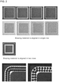
- a plurality of pieces of brazing material are preferably arranged as follows. Small blobs of brazing material are continuously fused on the joining region in a frame shape arrangement in an external view (overview).
- FIG. 2 illustrates specific arrangements, where sphere or dot shaped pieces of brazing material are aligned along the shape of the joining region.
- the upper side of FIG. 2 illustrates the brazing material aligned in a single row to form a frame shape.
- the brazing material may be aligned in a plurality of rows to form the frame shape.
- the continuous arrangement is not limited to such an arrangement that the pieces of brazing material are fused while being in contact with each other.
- the continuous arrangement encompasses such an arrangement that the pieces of brazing material are fused while being separated from each other.
- the latter is more preferable as will be described later.
- the number of a plurality of pieces of brazing material thus fused and the dimension (volume) of each piece of the brazing material are not particularly limited, insofar as the amount of the brazing material dispersed and fused is large enough to spread over the entire circumference of the joining region of the lid main body in the sealing step.
- the lid main body is more likely to be affected in terms of damage and sealing quality by the cross-sectional structure and the shape of the brazing material than by the dimension of the brazing material or by the number of pieces of the brazing material arranged.
- the brazing material made of a eutectic alloy is used because the eutectic alloy develops a fine eutectic structure.
- the fine eutectic structure obtained as the material structure of the brazing material a coarse solid phase can be eliminated, whereby stable sealing can be achieved.
- a coarse solid phase can be a cause of damage to the lid main body made of a translucent material.
- a coarse solid phase may in some cases have a high melting point, and thus may remain un-melted during brazing in the fusing step. In this case, it is possible for the joined portion formed after the sealing to be non-uniform in thickness, resulting in a possibility that airtightness is adversely affected.
- the presence of a coarse solid phase may cause some parts of the brazing material to have higher melting points. This may cause an excessive amount of thermal stress at these parts or uneven stress distribution in the joining interface.
- the material structure of the brazing material fused to the lid main body is preferably a fine structure.
- the material structure of a random cross section of at least one of the plurality of pieces of brazing material fused on the joining region is preferably a material structure made of a eutectic structure and an optional single phase having an equivalent circle diameter of equal to or less than 5 ⁇ m.
- the eutectic structure according to the present invention is equivalent in meaning to a general eutectic structure, and is one form of a material structure including a plurality of fine solid phases arranged in a complicated, periodic/composite manner.
- the material structure of the brazing material according to the present invention inevitably involves development of a eutectic structure having a periodic fine structure. In addition to this eutectic structure, it is possible that a single phase is generated and grows.
- the single phase is a solid phase that is coarse and/or atypical compared with solid phases of the eutectic structure.
- the single phase can be visually distinguished from the solid phase of the eutectic structure.
- the single phase may not necessarily be different from the solid phase of the eutectic structure in composition; the compositions of these phases may be the same or similar.
- the present inventors have studied and found that if the brazing material includes a coarse single phase with an equivalent circle diameter exceeding 5 ⁇ m, some of the brazing material may remain un-melted during the sealing, resulting in a possibility of damage to the lid main body or deteriorated airtightness.
- the single phase is optional.
- a particularly preferable material structure of the brazing material according to the present invention includes a eutectic structure alone, with substantially no single phase. When there are a plurality of single phases observed, it is necessary that an average of their equivalent circle diameters be 5 ⁇ m.
- the equivalent circle diameters of all the single phases in all the pieces of brazing material fused to the lid main body are 5 ⁇ m.
- a specific material structure of the brazing material fused to the lid main body according to the present invention will be described with a Au-Sn brazing material close to the eutectic composition used as an example.
- the Au-Sn brazing material close to the eutectic composition involves deposition of two types of solid phases, namely, a ⁇ phase (Au-37.6% by mass of Sn) and a ⁇ ' phase (Au-10.8% by mass of Sn).
- the eutectic structure is a material structure including fine ⁇ phases and fine ⁇ ' phases that are periodically arranged in complicated manner.
- the single phase generated in the Au-Sn brazing material of this composition includes ⁇ and ⁇ ' phases with the same compositions as the solid phases of the eutectic structure.
- the ⁇ phase and the ⁇ ' phase may deposit as single phases separately. These single phases are different from the ⁇ phase and the ⁇ ' phase of the eutectic structure in shape and size.
- the single phase has an outer shape such as a blob shape or an island shape, which is different from those of the phases in the eutectic structure, and has a coarse size.
- the single phase can be coarse with an equivalent circle diameter exceeding 5 ⁇ m.
- the solid phases that deposit in the Au-Sn brazing material close to the eutectic composition are the ⁇ phase and the ⁇ ' phase.
- the material structure preferably includes: the eutectic structure including the ⁇ phase and the ⁇ ' phase; and, optionally, a ⁇ phase or a ⁇ ' phase having an equivalent circle diameter of equal to or less than 5 ⁇ m.
- this material structure is preferably obtained on a random cross section of a randomly selected brazing material.
- the material structure is obtained on a plurality of any cross sections of all the pieces of brazing material.
- the dimension/shape of the brazing material fused to the joining region of the lid main body is not particularly limited. Still, the present inventors have found a preferable shape of the brazing material as a condition for preventing damage such as cracking and breaking on the lid main body at a higher level, in the step of fusing the brazing material on the lid main body and the step of melting again/curing the brazing material for sealing.
- the brazing material fused on the lid main body has a shape index (Is) that is preferably within a range of between 0.9 and 2.5, both inclusive.
- the shape index (Is) which is based on a relationship between the volume (V) of the brazing material and the joining area (A) between the lid main body and the brazing material, indicates that the brazing material with a substantial amount of volume needs to be fused with an appropriate joining area (contact area).
- an excessively large joining area relative to the volume of the brazing material results in relatively a large amount of thermal stress produced in the step of curing the brazing material in molten state.
- Low-rigidity translucent materials are largely affected by thermal stress.
- the brazing material is parameterized using the shape index (Is) as described above is for the purpose of preventing breaking of the lid in the step of fusing the brazing material and in the step of joining the lid main body and the package main body to each other.
- Is shape index
- the present inventors have found that when Is exceeds 2.5, the lid is damaged such as in the form of cracking. On the other hand, when Is is smaller than 0.9, this indicates that the joining area of the brazing material is too small. In this case, the lid main body is less likely to be damaged, but the adhesiveness of the brazing material to the lid main body is insufficient.
- the shape index (Is) is set to be within a range of between 0.9 and 2.5, both inclusive.
- the shape index (Is) of at least one of the pieces of brazing material on the lid main body is preferably within this range. More preferably, the average value of the shape indices (Is) of all the pieces of brazing material on the lid is within the range. Even more preferably, the shape indices (Is) of all the pieces of brazing material are within the range.
- the brazing material preferably has a shape that is substantially circular in a vertical projection view.
- Specific preferable shapes of the brazing material include a sphere shape and a semispherical shape, as well as a shape formed by two or more spheres stacked one on top of the other.
- FIG. 3 illustrates example relationships between the shape/dimension and the shape index (Is) of the brazing material.
- a plurality of pieces of brazing material having the same volume are illustrated in cross-sectional views taken along their center portions.
- the examples also illustrate a relationship between the shape index (Is) and a change in the joining area with the lid main body.
- FIG. 4 illustrates examples of the shape of the brazing material after the fusing.
- the examples illustrated in FIG. 3 and FIG. 4 indicate that the shape of the brazing material can be a sphere shape and a semispherical shape, and can also be a shape formed by two spheres stacked one on top of the other.
- the brazing material fused to the lid main body in the present invention may satisfy one of the above-described preferable conditions, namely: the preferable condition (the eutectic structure and a fine single phase) related to the material structure; and the preferable condition (shape index (Is)) related to the shape/dimension. It is also possible, however, that both of the conditions are satisfied, which can be realized by adjusting the fusing method/condition.
- Essential components of the sealing lid according to the present invention are: the lid main body made of a translucent material such as glass; and the brazing material made of a eutectic alloy and fused on the lid main body.
- the sealing lid further includes a metallized film and may further include a function film formed on one or both surfaces of the lid main body
- the brazing material is fused on the metallized film.
- the metallized film is used mainly for the purpose of increasing the adhesiveness of the brazing material to the lid main body.
- the brazing material is made of metal (eutectic alloy) and thus is a material of a type different from the translucent material such glass. Thus, depending on the composition, the brazing material might fail to be fixed due to insufficient adhesiveness to the lid main body.
- the metallized film made of metal is used to secure the adhesiveness of the brazing material, preventing the brazing material from falling off the lid main body.
- the metallized film may have either a single layer structure or a multi-layer structure. For a specific configuration of the metallized film, various types of metal layers are contemplated in accordance with the functions of the metallized film.
- a function of the metallized film is to improve the adhesiveness of the brazing material to the lid main body.
- the metallized film for such a purpose preferably has a first metal layer made of at least one of Au and Pt formed on the brazing material fusing surface. This is because Au or Pt has satisfactory adhesiveness to the brazing materials of the various specific examples described above.
- This first metal film may also include a single layer or multiple layers. Any one of Au or Pt may be used, or layers of these metals may be stacked (Au/Pt, Pt/Au). If the first metal film is excessively thin, the underlying layer may be exposes, resulting in insufficient adhesiveness.
- the first metal film may react with the brazing material in the joining step, resulting in a joining failure and/or a reduction in joining strength.
- the first metal film preferably has a film thickness in a range of between 0.01 ⁇ m and 1 ⁇ m, both inclusive.
- a specific and preferred configuration of the second metal layer is as follows.
- a metal layer made of any of Cr or Ti, which is highly active, is formed as an adhesion layer.
- a metal layer made of Ni is formed as a protective layer on the adhesion layer (Cr/Ni, Ti/Ni).
- Cr and Ti have high adhesiveness, their highly active property leaves a concern about oxidation and deterioration caused by outside air.
- the protective layer made of Ni is formed on the adhesion layer to prevent oxidation and the like of the adhesion layer, which is the underlying layer.
- the second metal layer is particularly preferably a metal layer made of the adhesion layer and the protective layer as described above.
- the adhesion layer has a film thickness within a range of between 0.04 ⁇ m and 0.1 ⁇ m, both inclusive
- the protective layer has a film thickness within a range of between 0.1 ⁇ m and 2 ⁇ m, both inclusive.
- the metallized film described above preferably has both of the first metal layer (Au, Pt), which serves as the brazing material fusing surface, and the second metal layer (Cr, Ti, Ni) on the lid main body surface side.
- Pt is also effectively used as a metal constituting the protective layer in the second metal layer.
- a metallized film (Cr/Pt, Ti/Pt) having the adhesion layer made of Cr or Ti and the protective layer made of Pt can also be used.
- Pt, which serves as the protective layer can also serve as the first metal layer. It is possible, therefore, to fuse the brazing material on the surface of the protective layer made of Pt.
- a metal made of Au may be additionally formed.
- the width of the diffusion region can be measured by an appropriate analysis method or device that determines presence or absence of the metal (Pt or Ni in many cases) component of the metallized film but that is not a component of the brazing material.
- the width of the diffusion region is preferably equal to or less than 1 ⁇ m.
- the lower limit of the width of the diffusion region, which is lower the better, is preferably 0.001 ⁇ m.
- the lid according to the present invention can be produced by fusing one or a plurality of pieces of brazing material on the lid main body made of a translucent material.
- the material structure and/or shape/dimension of the brazing material after the fusing are made appropriate.
- the following description focuses on a method for fusing the brazing material on the lid main body while achieving an appropriate material structure and/or shape/dimension of the brazing material.
- the brazing material can be fused by melting and then curing the solid brazing material on the lid main body. It is to be noted, however, that considering the shape (shape index (Is)) of the brazing material, the brazing material with a satisfactory shape is preferably fused. As a possible method for achieving a satisfactory shape index of the solid brazing material, it is possible to: place, on the lid main body, a plurality of blob shaped or granular pieces of preproduced brazing material of a predetermined size; and then heat the brazing material. When granular pieces of brazing material are arranged, they may be individually positioned by use of a jig and the like and heated in this state.
- a more preferable method for fusing the brazing material is to attach the brazing material in molten state to the lid main body and then cure the brazing material.
- a preferable material structure of the brazing material according to the present invention mainly includes a fine eutectic structure and include no coarse single phase. In order to form a fine eutectic structure, it is preferable to, in addition to adjusting the brazing material composition, rapidly cool the brazing material in molten state. In order to rapidly cool the brazing material in this manner, it is preferable to attach the molten brazing material to the lid main body and let the brazing material cool utilizing the lid main body and atmosphere.
- Attaching the brazing material in molten state to the lid main body is also preferable in terms of adjustment of the dimension/shape of the brazing material.
- the volume of the brazing material to be fused can be conveniently adjusted by adjusting the liquid measure of the liquid brazing material.
- the shape and the joining area of the molten brazing material hitting the lid main body can be changed based on the kinetic energy involved in the attaching of the molten brazing material. In this manner, the shape index (Is) of the brazing material can be adjusted.
- the brazing material can be fused even if the lid main body is kept at normal temperature. This is because the volume of a droplet of brazing material is much smaller than the volume of the lid main body, so that the brazing material is instantaneously cooled and cured upon contact with the lid main body.
- the lid main body may be cooled at the time of the fusing, if the brazing material is fused with the lid main body cooled to an excessively low temperature, the lid main body might be damaged by thermal shock caused by a temperature difference between the brazing material and the lid main body.
- the temperature of the lid main body in the step of fusing the droplets of the brazing material is preferably lower than the melting point of the brazing material by 100°C or lower. This is for the purpose of making the cooling rate high enough for the fused brazing material to have a fine material structure (eutectic structure).
- the brazing material in molten state is attached to the lid main body, and the brazing material is rapidly cooled and fused.
- a plurality of pieces of brazing material are usually fused on the joining region of the lid main body, and for this purpose, the plurality of pieces of molten brazing material are continuously discharged/supplied to be fused.
- the sealing lid according to the present invention is useful as a lid of a package using an optical element.
- the lid is made entirely of a translucent material such as glass. This makes the efficiency of use of light of the optical element in the package satisfactory.
- a brazing material made of a eutectic alloy is used as a joining material for hermetic sealing. Such brazing material is effective for firm hermetic sealing, has excellent durability, and is not deteriorated by ultraviolet rays or the like. Also, by controlling the brazing material at appropriate material structure and/or shape/dimension, the brazing material is fused without damaging the lid main body and advantageously functions in the sealing step.
- a lid main body was made of quartz glass, which is a translucent material.
- a Au-Sn brazing material which is a brazing material of a eutectic alloy, was fused using various methods to produce a sealing lid.
- the lid thus produced was tested for its joining performance relative to a package main body to evaluate whether the lid main body was damaged.
- the lid also underwent a sealing test to confirm its airtightness performance.
- the lid main body used in this embodiment is a flat plate (3.4 mm ⁇ 3.4 mm with a thickness of 0.3 mm) made of quartz glass or borosilicate glass.
- a metallized film was formed in a frame region (outer size: 3.2 mm ⁇ 3.2 mm, inner size: 2.5 mm ⁇ 2.5 mm) on the surface of the glass lid main body.
- the metallized film was formed by providing thin films of metals Cr (60 nm)/ Ni (200 nm)/ Au (100 nm) in this order from the lid main body surface.
- a metallized film formed by providing Ti (60 nm)/ Pt (200 nm)/ Au (100 nm) in this order was used.
- brazing material a Au-22% by mass Sn brazing material was used.
- the brazing material was fused to the lid main body to produce a lid by the following three different processes a to c.
- FIG. 5 illustrates a detailed configuration of this brazing material ejection device 101.
- the ejection device 101 includes: a tank 110, which contains a brazing material 201 and is kept at a controlled temperature so as to maintain the material in molten state; a chamber 111, which communicates with the tank 110; a diaphragm 112 and an aperture 113, which are for ejecting the brazing material 201 contained in the chamber 111; and a piezoelectric actuator 114, which drives the diaphragm 112.
- the piezoelectric actuator 114 is controlled and driven by a computer to cause a fixed amount of the brazing material 201 in the chamber 111 to be ejected through the nozzle.
- the volume and airborne speed of the ejected brazing material 202 is adjusted.
- the lid main body is placed on a stage that is movable in the X, Y, and Z directions. By driving this stage, the brazing material can be fused continuously in a frame shape on the lid main body.
- the brazing material was fused continuously in a row along the center position of the frame shaped metallized film, thereby shaping the brazing material into a frame.
- the size of molten metal droplets ejected was set to ⁇ 0.1 mm or ⁇ 0.125 mm in terms of sphere diameter, and the airborne speed of the brazing material was set to 1.6 m/second or higher.
- the number of pieces of the brazing material fused was calculated so that the thickness of the brazing material layer joined to the package main body would range from 10 to 25 ⁇ m, and the pieces were placed on the lid main body at substantially equal intervals.
- the temperature of the stage on which the lid main body was place was set to normal temperature.
- FIG. 7 illustrates an example external view of the lid produced by fusing the brazing material in this process a.
- FIG. 8 illustrates an example external view of the lid produced by fusing the brazing material in the process b.
- -Process c In this process, a piece of brazing material processed in a frame shape in advance was fused to the lid main body to produce a lid. This process serves as a comparative example relative to the above-described processes a and b. First, a Au-22% by mass Sn brazing material was punched out into a rectangular frame shape (outer size: 3.15mm ⁇ 3.15mm, inner size: 2.5mm ⁇ 2.5mm, thickness: 15 ⁇ m, 25 ⁇ m). Then, this preformed brazing material was placed on the lid main body, and reflowed and fused at 305°C in a non-oxidizing atmosphere.
- a material structure on a random cross section of the brazing material was observed.
- pieces of brazing material were randomly selected; the lid main body was cut in the vicinity of the selected piece of brazing material and embedded with resin; the lid main body was polished as appropriate to make the cross section of the brazing material exposed; and the cross section was subjected to an observation.
- the lids produced in the process c the lid was cut at an arbitrary position on the lid and embedded with resin, and then polished as appropriate to observe the material structure on the cross section of the brazing material.
- the shape index (Is) of the fused brazing material was measured.
- the brazing material was peeled off the lids produced, and the average value of volumes based on the mass of the brazing material collected and the density and the number of pieces of brazing material was determined as the volume (V) of a piece of brazing material.
- the joining area (A) of the brazing material the lid main bodies from which the brazing materials were peeled off were observed under a microscope; areas of the joining surfaces were measured; and the average of them was obtained.
- the volume (V) was determined from the dimensions of the pre-fused brazing material.
- the joining area (A) was calculated by measuring the profile of the post-fused brazing material.
- Table 1 lists: observation and measurement results of material structures, shapes, and dimensions of the brazing materials sorted by the production processes for the sealing lids produced according to this embodiment; and occurrence of damage in the lid main bodies.
- No. Production process Lid main body Number of brazing material Metallize d film Material structure Brazing material shape Diffusion region ( ⁇ m) Fused non-defective rate Single phase equivalent circle diameter Joining area ( ⁇ 10 -3 mm 2 ) Volume V ( ⁇ 10 -3 mm 3 ) Shape index (Is) A1 a quartz glass 56 Cr/Ni/Au 5 ⁇ m or less 3.74 0.57 0.7 0.5 9/10 A2 5 ⁇ m or less 6.23 0.59 0.9 0.5 10/10 A3 5 ⁇ m or less 12.47 0.52 1.4 0.5 10/10 A4 5 ⁇ m or less 18.70 0.55 1.7 0.5 10/10 A5 borosilicate glass Ti/Pt/Au 5 ⁇ m or less 21.75 0.55 1.8 0.5 10/10 A6
- FIG. 9 illustrates an example cross sectional structure of the brazing material (No. A4) after the molten brazing material was fused in the process a.
- the brazing material fused in the process a is expected to be less likely to include a coarse single phase.
- a single phase was identified based on the measurement criteria described above, with the result that the equivalent circle diameter was constantly 5 ⁇ m or less.
- the measurement results of the particle diameter of the single phase in Table 1 show that the brazing material for the lids produced in the process b tends to generate a single phase, in addition to a eutectic structure.
- the entire lid needs to be heated with the brazing material inserted in the jig, which requires a longer period of cooling time. This is presumably why the single phase is generated and grown.
- the pieces of brazing material (Nos. C1 and C2) preformed in a frame shape in the process c tend to case cracking in the glass lid main body in the fusing process.
- These pieces of brazing material had large shape indices (Is) ranging from 4.6 to 5.8.
- Such large shape indices (Is) are because of an excessively large joining area for the preformed brazing material in a frame shape. Since brazing materials are different from glass in thermal expansion/contraction behavior, a larger joining area results in a larger residual stress when the brazing material is cured. Brazing materials having a large joining area like this brazing material in a frame shape relatively tend to have cracking due to residual stress.
- FIG. 11 illustrates a cross sectional structure of the brazing material after the preform brazing material (brazing material thickness 25 ⁇ m) of No. C2 was fused. It was observed that a small region of the material structure of this brazing material was occupied by the eutectic structure, and the rest of the material structure was occupied by a large number of coarse single phases having a particle diameter exceeding 5 ⁇ m in terms of equivalent circle diameter. In this process, while the brazing material is being fused, the lid main body is heated together with the brazing material by reflow.
- the glass lid was examined under a stereoscopic microscope (20 times) for occurrence of cracking in the glass lid.
- a parameter used was the number of lid main bodies (10 pieces) in the fusing step of the brazing material described above. In other words, those products that were damaged in the lid main bodies during the fusing of the brazing material were determined to be defective without subjecting them to the sealing test.
- the sealing test was conducted on those products determined as non-defective after the fusing of the brazing material, and the non-defective rate was evaluated.
- the sealing lid according to the present invention uses a translucent material such as glass for the sealing lid, and uses a brazing material made of a eutectic alloy as a joining material for sealing.
- the use of each material has its own advantages.
- the present invention provides a package containing an optical element with effective efficiency of utilization of light and high durability.
- the present invention is suitable for sealing materials for various devices that use optical elements including light emitting elements such as LEDs and light receiving elements.
Landscapes
- Engineering & Computer Science (AREA)
- Chemical & Material Sciences (AREA)
- Mechanical Engineering (AREA)
- Ceramic Engineering (AREA)
- Materials Engineering (AREA)
- Organic Chemistry (AREA)
- Structural Engineering (AREA)
- Metallurgy (AREA)
- Led Device Packages (AREA)
- Physics & Mathematics (AREA)
- Condensed Matter Physics & Semiconductors (AREA)
- General Physics & Mathematics (AREA)
- Computer Hardware Design (AREA)
- Microelectronics & Electronic Packaging (AREA)
- Power Engineering (AREA)
- Light Receiving Elements (AREA)
- Joining Of Glass To Other Materials (AREA)
- Semiconductor Lasers (AREA)
Claims (13)
- Verschlussdeckel, der mit einem Package-Hauptkörper verbindbar ist, welcher aus Metall oder Keramik gebildet ist und ein optisches Element enthält, und der zur Herstellung eines hermetisch verschlossenen Package dient, wobei der Verschlussdeckel aufweist:einen Deckelhauptkörper aus einem lichtdurchlässigen Material, durch das sichtbares Licht und/oder UV-Licht und/oder Infrarotlicht hindurchtreten kann,wobei der Deckelhauptkörper einen Verbindungsbereich mit einer Rahmenform aufweist, die einer äußeren Umfangsform des Deckelhauptkörpers entspricht, wobei der Verbindungsbereich an einer Oberfläche des Deckelhauptkörpers ausgebildet ist, die mit dem Package-Hauptkörper verbunden werden soll,wobei eine Vielzahl von Stücken eines Lötmaterials aus einer eutektischen Legierung auf den Verbindungsbereich des Deckelhauptkörpers aufgeschmolzen wird, undeine metallisierte Folie, die zumindest eine Schicht aus Metall aufweist, auf zumindest einem Teil der Oberfläche des Deckelhauptkörpers vorgesehen ist, und das Lötmaterial auf die metallisierte Folie aufgeschmolzen wird, unddadurch gekennzeichnet, dassein Diffusionsbereich, der durch Diffusion eines Metallelements der metallisierten Folie in das Lötmaterial gebildet wird, eine Breite von 2 µm oder weniger aufweist.
- Verschlussdeckel nach Anspruch 1, dadurch gekennzeichnet, dass die Vielzahl von Stücken an Lötmaterial an dem Verbindungsbereich kontinuierlich geschmolzen werden, um eine Rahmenform zu bilden.
- Verschlussdeckel nach Anspruch 1 oder 2, wobei eine Materialstruktur eines zufälligen Querschnitts von zumindest einem der Vielzahl von Stücken von Lötmaterial eine eutektische Struktur aufweist und optional eine Einzelphase mit einem äquivalenten Kreisdurchmesser von gleich oder weniger als 5 µm aufweist.
- Verschlussdeckel nach einem der Ansprüche 1 bis 3, wobei zumindest eines der Vielzahl von Stücken von Lötmaterial eine im Wesentlichen kreisförmige Projektionsform aufweist.
- Verschlussdeckel nach einem der Ansprüche 1 bis 4, wobei zumindest eines der Vielzahl von Stücken von Lötmaterial einen Formindex (ls ) aufweist, der gleich oder größer als 0,9 und gleich oder kleiner als 2,5 ist, wobei der Formindex (ls ) durch eine Formel definiert ist:

- Verschlussdeckel nach einem der Ansprüche 1 bis 5, wobei das lichtdurchlässige Material des Deckelhauptkörpers aus Glas, Quarz, Saphir, Silizium oder Germanium hergestellt ist.
- Verschlussdeckel nach einem der Ansprüche 1 bis 6, wobei das Lötmaterial aus der eutektischen Legierung ein eutektisches Lötmaterial auf Au-Basis ist.
- Verschlussdeckel nach einem der Ansprüche 7, wobei das Lötmaterial aus der eutektischen Legierung ein Au-Sn-Lötmaterial ist.
- Verschlussdeckel nach Anspruch 1, wobei die metallisierte Folie eine erste Metallschicht aus zumindest einem der Elemente Au und Pt auf einer Lötmaterial-Schmelzfläche der metallisierten Folie umfasst.
- Verschlussdeckel nach Anspruch 9, wobei die metallisierte Folie eine zweite Metallschicht aus Mg und/oder Al und/oder Ti und/oder V und/oder Cr und/oder Mn und/oder Fe und/oder Co und/oder Ni und/oder Cu und/oder Zn und/oder Ga und/oder Ge und/oder Zr und/oder Nb und/oder Mo und/oder Ru und/oder Rh und/oder Pd und/oder Ag und/oder In und/oder Sn und/oder Sb und/oder Ta und/oder W und/oder Re und/oder Os und/oder Ir auf einer Oberfläche des Deckelhauptkörpers aufweist.
- Verschlussdeckel nach einem der Ansprüche 1 bis 10, wobei der Deckelhauptkörper auf einer Oberfläche oder beiden Oberflächen des Deckelhauptkörpers eine Funktionsfolie aufweist, wobei die Funktionsfolie zur Erhöhung der Durchlässigkeit oder des Reflexionsvermögens dient.
- Verfahren zum hermetischen Verschließen, umfassend das Verbinden eines Verschlussdeckels mit einem Package-Hauptkörper, wobei der verbundene Verschlussdeckel der Verschlussdeckel gemäß einem der Ansprüche 1 bis 11 ist.
- Package, aufweisend einen Verschlussdeckel gemäß einem der Ansprüche 1 bis 12.
Applications Claiming Priority (2)
| Application Number | Priority Date | Filing Date | Title |
|---|---|---|---|
| JP2018023249 | 2018-02-13 | ||
| PCT/JP2019/004772 WO2019159858A1 (ja) | 2018-02-13 | 2019-02-12 | 透光性材料からなる封止用のリッド |
Publications (4)
| Publication Number | Publication Date |
|---|---|
| EP3754699A1 EP3754699A1 (de) | 2020-12-23 |
| EP3754699A4 EP3754699A4 (de) | 2021-01-13 |
| EP3754699C0 EP3754699C0 (de) | 2023-11-22 |
| EP3754699B1 true EP3754699B1 (de) | 2023-11-22 |
Family
ID=67619447
Family Applications (1)
| Application Number | Title | Priority Date | Filing Date |
|---|---|---|---|
| EP19754079.2A Active EP3754699B1 (de) | 2018-02-13 | 2019-02-12 | Verschlussdeckel aus lichtdurchlässigem material |
Country Status (9)
| Country | Link |
|---|---|
| US (1) | US12002723B2 (de) |
| EP (1) | EP3754699B1 (de) |
| JP (1) | JP7182596B2 (de) |
| KR (1) | KR102417632B1 (de) |
| CN (1) | CN111712912B (de) |
| AU (1) | AU2019222263B2 (de) |
| MY (1) | MY203074A (de) |
| TW (1) | TWI713990B (de) |
| WO (1) | WO2019159858A1 (de) |
Families Citing this family (2)
| Publication number | Priority date | Publication date | Assignee | Title |
|---|---|---|---|---|
| JP7554694B2 (ja) * | 2021-03-12 | 2024-09-20 | スタンレー電気株式会社 | 半導体発光装置及びその製造方法 |
| JP7626344B2 (ja) * | 2021-09-22 | 2025-02-07 | 日亜化学工業株式会社 | 発光装置および発光装置の製造方法 |
Family Cites Families (19)
| Publication number | Priority date | Publication date | Assignee | Title |
|---|---|---|---|---|
| JPS58127474A (ja) * | 1982-01-25 | 1983-07-29 | Hitachi Ltd | 固体撮像装置 |
| JPH07249750A (ja) * | 1994-03-08 | 1995-09-26 | Toshiba Corp | 固体撮像装置の封止方法 |
| JPH0936690A (ja) | 1995-07-20 | 1997-02-07 | S I I Quartz Techno:Kk | 薄型水晶振動子 |
| JP2000311993A (ja) | 1999-04-28 | 2000-11-07 | Matsushita Electronics Industry Corp | 固体撮像装置の製造方法 |
| JP2003142621A (ja) | 2001-11-02 | 2003-05-16 | Kyocera Corp | 半導体装置 |
| US6627814B1 (en) * | 2002-03-22 | 2003-09-30 | David H. Stark | Hermetically sealed micro-device package with window |
| JP3878897B2 (ja) * | 2002-08-30 | 2007-02-07 | 京セラ株式会社 | 半導体素子収納用パッケージおよび半導体装置 |
| JP2007242642A (ja) | 2004-04-27 | 2007-09-20 | Matsushita Electric Ind Co Ltd | 受光素子、光ヘッド装置、及び光情報処理装置 |
| JP2006145610A (ja) | 2004-11-16 | 2006-06-08 | Shinko Electric Ind Co Ltd | 光学部品収納用パッケージ |
| KR100657945B1 (ko) * | 2005-01-21 | 2006-12-14 | 삼성전자주식회사 | 발열 댐을 구비한 광스캐너 패키지 |
| JP2007317787A (ja) * | 2006-05-24 | 2007-12-06 | Citizen Electronics Co Ltd | 発光装置およびその製造方法 |
| JP5373262B2 (ja) * | 2006-12-06 | 2013-12-18 | 株式会社デンソー | 半導体基板のキャップ固着方法 |
| KR20090106393A (ko) * | 2007-05-11 | 2009-10-08 | 다나까 기낀조꾸 고교 가부시끼가이샤 | 봉지 패키지용 리드 또는 케이스 및 그들의 제조방법 |
| JP5067030B2 (ja) | 2007-06-15 | 2012-11-07 | 三菱電機株式会社 | 半導体装置及びその製造方法 |
| WO2011013581A1 (ja) * | 2009-07-30 | 2011-02-03 | 日亜化学工業株式会社 | 発光装置及びその製造方法 |
| US8393526B2 (en) | 2010-10-21 | 2013-03-12 | Raytheon Company | System and method for packaging electronic devices |
| JP2015131340A (ja) | 2013-12-10 | 2015-07-23 | 住友金属鉱山株式会社 | Au−Sn−Ag系はんだ合金並びにこのAu−Sn−Ag系はんだ合金を用いて封止された電子部品及び電子部品搭載装置 |
| JP6787662B2 (ja) * | 2015-12-22 | 2020-11-18 | 京セラ株式会社 | シールリング、電子部品収納用パッケージ、電子デバイスおよびこれらの製造方法 |
| EP3408872A1 (de) * | 2016-01-28 | 2018-12-05 | Corning Incorporated | Verfahren zur ausgabe von quantenpunktmaterialien |
-
2019
- 2019-02-12 MY MYPI2020003979A patent/MY203074A/en unknown
- 2019-02-12 CN CN201980013082.4A patent/CN111712912B/zh active Active
- 2019-02-12 EP EP19754079.2A patent/EP3754699B1/de active Active
- 2019-02-12 JP JP2020500467A patent/JP7182596B2/ja active Active
- 2019-02-12 WO PCT/JP2019/004772 patent/WO2019159858A1/ja not_active Ceased
- 2019-02-12 KR KR1020207025192A patent/KR102417632B1/ko active Active
- 2019-02-12 AU AU2019222263A patent/AU2019222263B2/en active Active
- 2019-02-12 US US16/967,207 patent/US12002723B2/en active Active
- 2019-02-13 TW TW108104692A patent/TWI713990B/zh active
Also Published As
| Publication number | Publication date |
|---|---|
| US12002723B2 (en) | 2024-06-04 |
| CN111712912A (zh) | 2020-09-25 |
| EP3754699A1 (de) | 2020-12-23 |
| JP7182596B2 (ja) | 2022-12-02 |
| KR102417632B1 (ko) | 2022-07-07 |
| TWI713990B (zh) | 2020-12-21 |
| EP3754699C0 (de) | 2023-11-22 |
| CN111712912B (zh) | 2023-12-22 |
| MY203074A (en) | 2024-06-06 |
| AU2019222263A1 (en) | 2020-09-24 |
| US20200365474A1 (en) | 2020-11-19 |
| JPWO2019159858A1 (ja) | 2021-01-28 |
| WO2019159858A1 (ja) | 2019-08-22 |
| KR20200116485A (ko) | 2020-10-12 |
| EP3754699A4 (de) | 2021-01-13 |
| TW202005049A (zh) | 2020-01-16 |
| AU2019222263B2 (en) | 2022-02-24 |
Similar Documents
| Publication | Publication Date | Title |
|---|---|---|
| EP3754699B1 (de) | Verschlussdeckel aus lichtdurchlässigem material | |
| JP4245924B2 (ja) | 電子部品用パッケージおよびその製造方法 | |
| US10639749B2 (en) | Cu core ball, solder joint, solder paste and formed solder | |
| TWI784013B (zh) | 窗材、光學封裝 | |
| JP2005101481A (ja) | 半導体装置用キャップ | |
| CN101622706B (zh) | 气密密封用盖、电子部件容纳用封装和电子部件容纳用封装的制造方法 | |
| KR102656315B1 (ko) | 창재, 광학 패키지 | |
| KR20110041533A (ko) | Au-Ga-In계 납재 | |
| US20250125578A1 (en) | Composite body and airtight package comprising composite body | |
| US20150305145A1 (en) | Joining methods for bulk metallic glasses | |
| US6961505B2 (en) | Metal holder, optical component composite body and manufacturing method | |
| EP1610380B1 (de) | Hermetischer Deckel und seine Herstellung | |
| JP7473877B2 (ja) | 蓋部材の製造方法 | |
| JP4456980B2 (ja) | 半導体装置用キャップ | |
| JP2010226064A (ja) | パッケージ封止用のリッド及びその製造方法 | |
| TW202006147A (zh) | Cu核球、焊接頭、焊膏及泡沫焊料 |
Legal Events
| Date | Code | Title | Description |
|---|---|---|---|
| STAA | Information on the status of an ep patent application or granted ep patent |
Free format text: STATUS: THE INTERNATIONAL PUBLICATION HAS BEEN MADE |
|
| PUAI | Public reference made under article 153(3) epc to a published international application that has entered the european phase |
Free format text: ORIGINAL CODE: 0009012 |
|
| STAA | Information on the status of an ep patent application or granted ep patent |
Free format text: STATUS: REQUEST FOR EXAMINATION WAS MADE |
|
| REG | Reference to a national code |
Ref country code: DE Ref legal event code: R079 Free format text: PREVIOUS MAIN CLASS: H01L0023020000 Ipc: B23K0035300000 Ref document number: 602019041911 Country of ref document: DE |
|
| 17P | Request for examination filed |
Effective date: 20200825 |
|
| AK | Designated contracting states |
Kind code of ref document: A1 Designated state(s): AL AT BE BG CH CY CZ DE DK EE ES FI FR GB GR HR HU IE IS IT LI LT LU LV MC MK MT NL NO PL PT RO RS SE SI SK SM TR |
|
| AX | Request for extension of the european patent |
Extension state: BA ME |
|
| A4 | Supplementary search report drawn up and despatched |
Effective date: 20201216 |
|
| RIC1 | Information provided on ipc code assigned before grant |
Ipc: C04B 37/04 20060101ALN20201210BHEP Ipc: H01L 33/52 20100101ALN20201210BHEP Ipc: H01L 23/10 20060101ALI20201210BHEP Ipc: H01L 31/0203 20140101ALN20201210BHEP Ipc: B23K 35/30 20060101AFI20201210BHEP Ipc: H01L 21/50 20060101ALI20201210BHEP |
|
| DAV | Request for validation of the european patent (deleted) | ||
| DAX | Request for extension of the european patent (deleted) | ||
| STAA | Information on the status of an ep patent application or granted ep patent |
Free format text: STATUS: EXAMINATION IS IN PROGRESS |
|
| 17Q | First examination report despatched |
Effective date: 20221007 |
|
| GRAP | Despatch of communication of intention to grant a patent |
Free format text: ORIGINAL CODE: EPIDOSNIGR1 |
|
| STAA | Information on the status of an ep patent application or granted ep patent |
Free format text: STATUS: GRANT OF PATENT IS INTENDED |
|
| INTG | Intention to grant announced |
Effective date: 20230626 |
|
| GRAS | Grant fee paid |
Free format text: ORIGINAL CODE: EPIDOSNIGR3 |
|
| GRAA | (expected) grant |
Free format text: ORIGINAL CODE: 0009210 |
|
| STAA | Information on the status of an ep patent application or granted ep patent |
Free format text: STATUS: THE PATENT HAS BEEN GRANTED |
|
| AK | Designated contracting states |
Kind code of ref document: B1 Designated state(s): AL AT BE BG CH CY CZ DE DK EE ES FI FR GB GR HR HU IE IS IT LI LT LU LV MC MK MT NL NO PL PT RO RS SE SI SK SM TR |
|
| REG | Reference to a national code |
Ref country code: GB Ref legal event code: FG4D |
|
| REG | Reference to a national code |
Ref country code: CH Ref legal event code: EP Ref country code: DE Ref legal event code: R096 Ref document number: 602019041911 Country of ref document: DE |
|
| REG | Reference to a national code |
Ref country code: IE Ref legal event code: FG4D |
|
| U01 | Request for unitary effect filed |
Effective date: 20231122 |
|
| U07 | Unitary effect registered |
Designated state(s): AT BE BG DE DK EE FI FR IT LT LU LV MT NL PT SE SI Effective date: 20231127 |
|
| U20 | Renewal fee for the european patent with unitary effect paid |
Year of fee payment: 6 Effective date: 20240222 |
|
| PG25 | Lapsed in a contracting state [announced via postgrant information from national office to epo] |
Ref country code: GR Free format text: LAPSE BECAUSE OF FAILURE TO SUBMIT A TRANSLATION OF THE DESCRIPTION OR TO PAY THE FEE WITHIN THE PRESCRIBED TIME-LIMIT Effective date: 20240223 |
|
| PG25 | Lapsed in a contracting state [announced via postgrant information from national office to epo] |
Ref country code: IS Free format text: LAPSE BECAUSE OF FAILURE TO SUBMIT A TRANSLATION OF THE DESCRIPTION OR TO PAY THE FEE WITHIN THE PRESCRIBED TIME-LIMIT Effective date: 20240322 |
|
| PG25 | Lapsed in a contracting state [announced via postgrant information from national office to epo] |
Ref country code: ES Free format text: LAPSE BECAUSE OF FAILURE TO SUBMIT A TRANSLATION OF THE DESCRIPTION OR TO PAY THE FEE WITHIN THE PRESCRIBED TIME-LIMIT Effective date: 20231122 |
|
| PG25 | Lapsed in a contracting state [announced via postgrant information from national office to epo] |
Ref country code: IS Free format text: LAPSE BECAUSE OF FAILURE TO SUBMIT A TRANSLATION OF THE DESCRIPTION OR TO PAY THE FEE WITHIN THE PRESCRIBED TIME-LIMIT Effective date: 20240322 Ref country code: GR Free format text: LAPSE BECAUSE OF FAILURE TO SUBMIT A TRANSLATION OF THE DESCRIPTION OR TO PAY THE FEE WITHIN THE PRESCRIBED TIME-LIMIT Effective date: 20240223 Ref country code: ES Free format text: LAPSE BECAUSE OF FAILURE TO SUBMIT A TRANSLATION OF THE DESCRIPTION OR TO PAY THE FEE WITHIN THE PRESCRIBED TIME-LIMIT Effective date: 20231122 |
|
| PG25 | Lapsed in a contracting state [announced via postgrant information from national office to epo] |
Ref country code: RS Free format text: LAPSE BECAUSE OF FAILURE TO SUBMIT A TRANSLATION OF THE DESCRIPTION OR TO PAY THE FEE WITHIN THE PRESCRIBED TIME-LIMIT Effective date: 20231122 Ref country code: PL Free format text: LAPSE BECAUSE OF FAILURE TO SUBMIT A TRANSLATION OF THE DESCRIPTION OR TO PAY THE FEE WITHIN THE PRESCRIBED TIME-LIMIT Effective date: 20231122 Ref country code: NO Free format text: LAPSE BECAUSE OF FAILURE TO SUBMIT A TRANSLATION OF THE DESCRIPTION OR TO PAY THE FEE WITHIN THE PRESCRIBED TIME-LIMIT Effective date: 20240222 Ref country code: HR Free format text: LAPSE BECAUSE OF FAILURE TO SUBMIT A TRANSLATION OF THE DESCRIPTION OR TO PAY THE FEE WITHIN THE PRESCRIBED TIME-LIMIT Effective date: 20231122 |
|
| PG25 | Lapsed in a contracting state [announced via postgrant information from national office to epo] |
Ref country code: CZ Free format text: LAPSE BECAUSE OF FAILURE TO SUBMIT A TRANSLATION OF THE DESCRIPTION OR TO PAY THE FEE WITHIN THE PRESCRIBED TIME-LIMIT Effective date: 20231122 |
|
| PG25 | Lapsed in a contracting state [announced via postgrant information from national office to epo] |
Ref country code: SK Free format text: LAPSE BECAUSE OF FAILURE TO SUBMIT A TRANSLATION OF THE DESCRIPTION OR TO PAY THE FEE WITHIN THE PRESCRIBED TIME-LIMIT Effective date: 20231122 |
|
| PG25 | Lapsed in a contracting state [announced via postgrant information from national office to epo] |
Ref country code: SM Free format text: LAPSE BECAUSE OF FAILURE TO SUBMIT A TRANSLATION OF THE DESCRIPTION OR TO PAY THE FEE WITHIN THE PRESCRIBED TIME-LIMIT Effective date: 20231122 Ref country code: SK Free format text: LAPSE BECAUSE OF FAILURE TO SUBMIT A TRANSLATION OF THE DESCRIPTION OR TO PAY THE FEE WITHIN THE PRESCRIBED TIME-LIMIT Effective date: 20231122 Ref country code: RO Free format text: LAPSE BECAUSE OF FAILURE TO SUBMIT A TRANSLATION OF THE DESCRIPTION OR TO PAY THE FEE WITHIN THE PRESCRIBED TIME-LIMIT Effective date: 20231122 Ref country code: CZ Free format text: LAPSE BECAUSE OF FAILURE TO SUBMIT A TRANSLATION OF THE DESCRIPTION OR TO PAY THE FEE WITHIN THE PRESCRIBED TIME-LIMIT Effective date: 20231122 |
|
| REG | Reference to a national code |
Ref country code: DE Ref legal event code: R097 Ref document number: 602019041911 Country of ref document: DE |
|
| PLBE | No opposition filed within time limit |
Free format text: ORIGINAL CODE: 0009261 |
|
| STAA | Information on the status of an ep patent application or granted ep patent |
Free format text: STATUS: NO OPPOSITION FILED WITHIN TIME LIMIT |
|
| PG25 | Lapsed in a contracting state [announced via postgrant information from national office to epo] |
Ref country code: MC Free format text: LAPSE BECAUSE OF FAILURE TO SUBMIT A TRANSLATION OF THE DESCRIPTION OR TO PAY THE FEE WITHIN THE PRESCRIBED TIME-LIMIT Effective date: 20231122 |
|
| REG | Reference to a national code |
Ref country code: CH Ref legal event code: PL |
|
| PG25 | Lapsed in a contracting state [announced via postgrant information from national office to epo] |
Ref country code: CH Free format text: LAPSE BECAUSE OF NON-PAYMENT OF DUE FEES Effective date: 20240229 |
|
| GBPC | Gb: european patent ceased through non-payment of renewal fee |
Effective date: 20240222 |
|
| 26N | No opposition filed |
Effective date: 20240823 |
|
| PG25 | Lapsed in a contracting state [announced via postgrant information from national office to epo] |
Ref country code: CH Free format text: LAPSE BECAUSE OF NON-PAYMENT OF DUE FEES Effective date: 20240229 |
|
| PG25 | Lapsed in a contracting state [announced via postgrant information from national office to epo] |
Ref country code: GB Free format text: LAPSE BECAUSE OF NON-PAYMENT OF DUE FEES Effective date: 20240222 |
|
| PG25 | Lapsed in a contracting state [announced via postgrant information from national office to epo] |
Ref country code: IE Free format text: LAPSE BECAUSE OF NON-PAYMENT OF DUE FEES Effective date: 20240212 |
|
| PG25 | Lapsed in a contracting state [announced via postgrant information from national office to epo] |
Ref country code: IE Free format text: LAPSE BECAUSE OF NON-PAYMENT OF DUE FEES Effective date: 20240212 Ref country code: GB Free format text: LAPSE BECAUSE OF NON-PAYMENT OF DUE FEES Effective date: 20240222 |
|
| U20 | Renewal fee for the european patent with unitary effect paid |
Year of fee payment: 7 Effective date: 20250221 |
|
| PG25 | Lapsed in a contracting state [announced via postgrant information from national office to epo] |
Ref country code: CY Free format text: LAPSE BECAUSE OF FAILURE TO SUBMIT A TRANSLATION OF THE DESCRIPTION OR TO PAY THE FEE WITHIN THE PRESCRIBED TIME-LIMIT; INVALID AB INITIO Effective date: 20190212 |
|
| PG25 | Lapsed in a contracting state [announced via postgrant information from national office to epo] |
Ref country code: HU Free format text: LAPSE BECAUSE OF FAILURE TO SUBMIT A TRANSLATION OF THE DESCRIPTION OR TO PAY THE FEE WITHIN THE PRESCRIBED TIME-LIMIT; INVALID AB INITIO Effective date: 20190212 |
|
| PG25 | Lapsed in a contracting state [announced via postgrant information from national office to epo] |
Ref country code: TR Free format text: LAPSE BECAUSE OF FAILURE TO SUBMIT A TRANSLATION OF THE DESCRIPTION OR TO PAY THE FEE WITHIN THE PRESCRIBED TIME-LIMIT Effective date: 20231122 |