EP3754680A1 - Dispositif de commutation pour un appareil de cuisson doté d'un espace de cuisson pouvant être fermé par une porte et appareil de cuisson - Google Patents
Dispositif de commutation pour un appareil de cuisson doté d'un espace de cuisson pouvant être fermé par une porte et appareil de cuisson Download PDFInfo
- Publication number
- EP3754680A1 EP3754680A1 EP20174311.9A EP20174311A EP3754680A1 EP 3754680 A1 EP3754680 A1 EP 3754680A1 EP 20174311 A EP20174311 A EP 20174311A EP 3754680 A1 EP3754680 A1 EP 3754680A1
- Authority
- EP
- European Patent Office
- Prior art keywords
- switch
- switch device
- coupling element
- cooking
- door
- Prior art date
- Legal status (The legal status is an assumption and is not a legal conclusion. Google has not performed a legal analysis and makes no representation as to the accuracy of the status listed.)
- Granted
Links
- 238000010411 cooking Methods 0.000 title claims abstract description 68
- 230000008878 coupling Effects 0.000 claims abstract description 101
- 238000010168 coupling process Methods 0.000 claims abstract description 101
- 238000005859 coupling reaction Methods 0.000 claims abstract description 101
- 238000011161 development Methods 0.000 description 9
- 230000018109 developmental process Effects 0.000 description 9
- 230000000903 blocking effect Effects 0.000 description 5
- 230000005540 biological transmission Effects 0.000 description 1
- 238000011156 evaluation Methods 0.000 description 1
Images


Classifications
-
- H—ELECTRICITY
- H01—ELECTRIC ELEMENTS
- H01H—ELECTRIC SWITCHES; RELAYS; SELECTORS; EMERGENCY PROTECTIVE DEVICES
- H01H3/00—Mechanisms for operating contacts
- H01H3/02—Operating parts, i.e. for operating driving mechanism by a mechanical force external to the switch
- H01H3/16—Operating parts, i.e. for operating driving mechanism by a mechanical force external to the switch adapted for actuation at a limit or other predetermined position in the path of a body, the relative movement of switch and body being primarily for a purpose other than the actuation of the switch, e.g. for a door switch, a limit switch, a floor-levelling switch of a lift
- H01H3/161—Operating parts, i.e. for operating driving mechanism by a mechanical force external to the switch adapted for actuation at a limit or other predetermined position in the path of a body, the relative movement of switch and body being primarily for a purpose other than the actuation of the switch, e.g. for a door switch, a limit switch, a floor-levelling switch of a lift for actuation by moving a closing member, e.g. door, cover or lid
- H01H3/163—Operating parts, i.e. for operating driving mechanism by a mechanical force external to the switch adapted for actuation at a limit or other predetermined position in the path of a body, the relative movement of switch and body being primarily for a purpose other than the actuation of the switch, e.g. for a door switch, a limit switch, a floor-levelling switch of a lift for actuation by moving a closing member, e.g. door, cover or lid associated with locking or manipulating means of the closing member
-
- F—MECHANICAL ENGINEERING; LIGHTING; HEATING; WEAPONS; BLASTING
- F24—HEATING; RANGES; VENTILATING
- F24C—DOMESTIC STOVES OR RANGES ; DETAILS OF DOMESTIC STOVES OR RANGES, OF GENERAL APPLICATION
- F24C7/00—Stoves or ranges heated by electric energy
- F24C7/08—Arrangement or mounting of control or safety devices
- F24C7/082—Arrangement or mounting of control or safety devices on ranges, e.g. control panels, illumination
- F24C7/085—Arrangement or mounting of control or safety devices on ranges, e.g. control panels, illumination on baking ovens
-
- H—ELECTRICITY
- H05—ELECTRIC TECHNIQUES NOT OTHERWISE PROVIDED FOR
- H05B—ELECTRIC HEATING; ELECTRIC LIGHT SOURCES NOT OTHERWISE PROVIDED FOR; CIRCUIT ARRANGEMENTS FOR ELECTRIC LIGHT SOURCES, IN GENERAL
- H05B6/00—Heating by electric, magnetic or electromagnetic fields
- H05B6/64—Heating using microwaves
- H05B6/6414—Aspects relating to the door of the microwave heating apparatus
- H05B6/6417—Door interlocks of the microwave heating apparatus and related circuits
-
- F—MECHANICAL ENGINEERING; LIGHTING; HEATING; WEAPONS; BLASTING
- F24—HEATING; RANGES; VENTILATING
- F24C—DOMESTIC STOVES OR RANGES ; DETAILS OF DOMESTIC STOVES OR RANGES, OF GENERAL APPLICATION
- F24C15/00—Details
- F24C15/02—Doors specially adapted for stoves or ranges
-
- H—ELECTRICITY
- H01—ELECTRIC ELEMENTS
- H01H—ELECTRIC SWITCHES; RELAYS; SELECTORS; EMERGENCY PROTECTIVE DEVICES
- H01H3/00—Mechanisms for operating contacts
- H01H3/32—Driving mechanisms, i.e. for transmitting driving force to the contacts
Definitions
- the invention relates to a switch device for a cooking device with a cooking space that can be closed by a door and a cooking device with a cooking space that can be closed by a door and a switch device.
- Such switch devices for cooking devices with a cooking space that can be closed by a door and cooking devices with a cooking space that can be closed by a door and a switch device are already known from the prior art in a large number of embodiments.
- the invention thus poses the problem of improving a switch device for a cooking device with a cooking space that can be closed by a door and a cooking device with a cooking space that can be closed by a door and a switch device.
- a switch device for a cooking appliance with a cooking space that can be closed by a door with the features of claim 1, according to which the switch device has at least one switch, an actuating unit for actuating the switch and a coupling unit for coupling the actuating unit to two plungers of the door comprises, wherein the coupling unit has a separate slide for each plunger, and wherein the two slides are coupled to one another by means of a coupling element in such a way that the actuation unit actuates the switch depending on a simultaneous actuation of the two slides by means of the two plungers.
- a cooking device with the features of claim 10, according to which the cooking device comprises a cooking space that can be closed by a door and at least one switch device with at least one switch, at least one cooking device function of the cooking device being able to be switched on depending on a switching state of the switch, and wherein at least one of the at least one switch device is designed according to one of claims 1 to 9 and the door has two plungers corresponding to this switch device.
- the advantage that can be achieved with the invention is in particular that a switch device for a cooking device with a cooking space that can be closed by a door and a cooking device with a cooking space that can be closed by a door and a switch device are improved.
- some states provide for as Microwave devices trained cooking devices very high requirements with regard to their manipulation security. Microwave devices that are to be sold in these countries must be equipped accordingly.
- the plungers arranged on the door of the cooking device for actuating the at least one switch of the known switch device for such cooking devices must be very long. Accordingly, these tappets are very bulky and not very user-friendly.
- the invention makes it possible to design the switch device and cooking appliances equipped with it in one variant for countries with lower security requirements and in another variant for countries with higher security requirements without changing the basic structure of the switch device.
- the switch device according to the invention can be freely selected within wide suitable limits in terms of type, function, dimensions, material, arrangement and number.
- the coupling unit has a base plate on which the two slides are movably arranged and guided. In this way, the arrangement and guidance of the slides are implemented in a structurally simple and robust manner.
- the coupling element on one side and the two slides on the other side each have corresponding joint parts, each pair of corresponding joint parts forming a joint. This enables the coupling element and its articulated connection to the two slides in a particularly simple constructive manner.
- the coupling element and the base plate each have two locking parts corresponding to one another in pairs, the locking parts being designed such that one of the two locking parts of the coupling element when the one slide is actuated and when the other slide is not actuated, it is locked with the corresponding locking part of the base plate.
- This enables the movement of each of the two slides to be blocked in a structurally particularly simple manner and thus effectively prevents undesired actuation of the at least one switch of the switch device according to the invention by means of the actuation unit.
- the coupling element has a contact section, the contact section actuating the actuating unit when the two slides are actuated simultaneously by means of the tappet of the door such that the actuating unit actuates the switch.
- the power transmission from the coupling unit on the one hand and the actuating unit on the other hand is implemented in a component-saving and thus space-saving manner.
- the switch device has a plurality of switches, one of the switches being designed as a monitor switch. In this way, proper functioning of the switch device according to the invention can be checked, for example by means of an evaluation unit of the cooking appliance.
- the switch device has a plurality of switches, at least two of the plurality of switches being able to be actuated successively by means of the actuation unit.
- the structural design of the switch device according to the invention is simple even with a plurality of switches. Furthermore, this reduces the number of components and thus the space required.
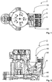
- Figs. 1 to 12 shows an embodiment of a switch device according to the invention for a cooking appliance with a cooking space that can be closed by a door.
- the cooking device designed as a microwave device is essentially not shown.
- the switch device 2 comprises three switches 4, 6, 8, an actuating unit 10 for actuating the switches 4, 6, 8 and a coupling unit 12 for coupling the actuating unit 10 to two plungers 14 of the door of the cooking appliance.
- the switch 4 is designed as a load switch
- the switch 6 in the present exemplary embodiment is designed as a monitor switch
- the switch 8 is designed as a signal switch.
- the coupling unit 12 has a separate slide 16, 18 for each plunger 14, the two slides 16, 18 by means of a Coupling elements 20 are coupled to one another in such a way that the actuation unit 10 actuates the switches 4, 6, 8 as a function of a simultaneous actuation of the two slides 16, 18 by means of the two tappets 14.
- the coupling unit 12 has a base plate 22 on which the two slides 16, 18 are movably arranged and guided.
- the coupling element 20 on the one hand and the two slides 16, 18 on the other side each have joint parts 24, 26, 28, 30 that correspond to one another, each pairing 24, 26; 28, 30 of mutually corresponding joint parts 24, 26, 28, 30 each form a joint.
- the two joint parts 26, 30 of the coupling element 20 are each designed as peg-like projections of a base part 32 of the coupling element 20 and the joint part 24, 28 of each of the two slides 16, 18 is designed as a receptacle for the corresponding projection 26, 30.
- the receptacle 24 of the slide 16 is assigned to the projection 26 of the coupling element 20 and the receptacle 28 of the slide 18 is assigned to the projection 30 of the coupling element 20.
- the coupling element 20 and the base plate 22 each have two locking parts 34, 36, 38, 40 which correspond to one another in pairs, the locking parts 34, 36, 38, 40 being designed such that one of the two locking parts 34, 38 of the coupling element 20 is at when the one slide 16, 18 is actuated and when the other slide 18, 16 is not actuated, it is locked with the corresponding locking part 36, 40 of the base plate 22.
- the locking part 34 of the coupling element 20 locks with the corresponding locking part 36 of the base plate 22. This case is not shown in the figures.
- the two locking parts 34, 38 of the coupling element 20 are each designed as a hook and the two locking parts 36, 40 of the base plate 22 are each designed as a hook holder.
- the coupling element 20 and the base plate 22 in the present exemplary embodiment have further locking parts in addition to the locking parts 34, 36, 38, 40 mentioned and explained above, with only the further locking parts 42 in the figures , 44 of the coupling element 20 are visible. See in particular the Figures 10 and 11 .
- the two further locking parts 42, 44 of the coupling element 20 are also each designed as a hook and the corresponding further locking parts of the base plate 22 are also each designed as a hook receptacle.
- the further locking parts 42, 44 of the coupling element 20 on the one hand interact with the further locking parts of the base plate 22 on the other side analogously to the locking parts 34, 36, 38, 40 explained above.
- the coupling element 20 has a contact section 46, the contact section 46 actuating the actuating unit 10 when the two slides 16, 18 are actuated simultaneously by means of the tappet 14 of the door such that the actuating unit 10 actuates the switches 4, 6, 8.
- the actuation unit 10 has an actuation lever 48, the actuation unit 10 being designed in such a way that the switches 4, 6, 8 can be actuated successively, i.e. one after the other, by means of the actuation lever 48.
- the cooking appliance which is essentially not shown, ie the microwave appliance, has a total of two switch devices in the present exemplary embodiment, one of the two switch devices being designed as the switch device 2.
- the two switch devices are each arranged on one side of the front of the cooking appliance.
- the door of the cooking appliance is open and the switch device 2 is located in the from the Fig. 1, 2 , 3 and 6th shown position, i.e. in the rest position.
- the switches 4, 6, 8 are not operated.
- the slides 16, 18 of the coupling unit 12 of the switch device 2 are each except for a 3 mm large slot in a housing, not shown, of the cooking device completely surrounded by the housing and thus only accessible from the outside through the aforementioned slots in the housing.
- a manipulation attempt is now made, that is, an undesired actuation of the switch device 2, for example by a child who pushes a nail or the like, for example through the slot in the housing of the cooking appliance associated with the slide 18.
- the child reaches the slide 18 with the nail and presses it, for example against a spring force of a spring, not shown, in the plane of the drawing Fig. 3 to the left.
- the coupling unit 12 of the switch device 2 After a distance of about 2.5 mm, the coupling unit 12 of the switch device 2 reaches the out of the Fig. 5 apparent location, namely a blocked location. Due to the fact that only the slide 18 and not additionally the slide 16 has been actuated, the coupling element 20 of the coupling unit 12 is perpendicular to the image plane of FIG Fig.
- the locking part 38 of the coupling element 20 comes into engagement with the locking part 40 of the base plate 22 of the coupling unit 12, namely locked.
- the further locking part 42 of the coupling element 20 engages with the corresponding locking part of the base plate 22, so that the coupling element 20 is locked twice to the base plate 22 by means of the aforementioned locking parts 38, 40, 42.
- the above-mentioned locking function also works when a greater force is introduced, for example by means of the nail. Accordingly, the coupling unit 12 remains securely in its blocking position even when a greater force is introduced and thus prevents undesired actuation of the switches 4, 6, 8 of the switch device 2.
- the same also applies in the event that, instead of the slide 18, only the slide 16 is actuated in an undesired manner, for example by means of the above-mentioned nail.
- the child reaches the slide 16 with the nail and presses it, for example against a spring force of a spring, not shown, in the plane of the drawing Fig. 3 to the left.
- the coupling unit 12 of the switch device 2 arrives at a Fig. 5 analog position, namely a blocking position. Due to the fact that only the slide 16 and not additionally the slide 18 has been actuated, the coupling element 20 of the coupling unit 12 is perpendicular to the image plane of FIG Fig.
- the aforementioned locking also works with a larger one Force introduction, for example by means of the nail.
- the coupling unit 12 also remains securely in its blocking position when a greater force is introduced, and thus again prevents undesired actuation of the switches 4, 6, 8 of the switch device 2.
- the slides 16, 18, When the switch device 2 is properly actuated, i.e. when the switch device 2 is actuated simultaneously by means of the plunger 14 of the door of the cooking appliance when the door is closed, the slides 16, 18, for example, in each case against the spring force of the above-mentioned springs, by means of the plunger 14 of the in the Fig. 3 shown rest position initially in the Fig. 4 intermediate position shown and then transferred to the end position, not shown. How out Fig. 4 As can be seen, the slides 16, 18 can, when they are simultaneously actuated by means of the tappet 14 of the door, beyond the blocking position of the coupling unit 12 in the plane of the drawing Fig. 3 be moved further to the left.
- the locking parts 34, 36, 38, 40, 42, 44 of the coupling element 20 and the base plate 22 of the coupling unit 12 do not engage with one another. This is not because the coupling element 20 is not rotated during the simultaneous actuation of the slides 16, 18 by means of the tappet 14 of the door.
- the coupling element 20 is neither clockwise nor counterclockwise around the perpendicular to the image plane of Fig. 4 extending axis of rotation, not shown, rotated.
- the coupling element 20 of the coupling unit 12 with its contact section 46 engages with the actuation unit 10, namely the actuation lever 48 of the actuation unit 10.
- the coupling element 20 rotates the actuation lever 48 of the actuation unit 10 clockwise about an axis of rotation 50, so that the actuation unit 10 engages the switch 6 designed as a monitor switch with the actuation lever 48 when the slide 16, 18 is about 4.5 mm .
- the switch 6 is thus operated by means of the operating unit 10, namely the operating lever 48. See also Fig. 4
- the coupling element 20 pushes the actuating lever 48 in the plane of the drawing Fig. 2 further to the left, so that the actuating lever 48 is rotated further clockwise about the axis of rotation 50.
- the actuating lever 48 engages with the switch 8 designed as a signal switch.
- the switch 8 is therefore also actuated by the actuating unit 10, namely the actuating lever 48.
- the invention makes it possible to design the switch device and cooking devices equipped with it, for example microwave devices or cooking devices with a microwave function, in one variant for countries with lower security requirements and in another variant for countries with higher security requirements, without changing the basic structure of the switch device .
- the two slides and the coupling element are designed as a single, essentially rigid component for countries with lower safety requirements.
- the coupling unit thus only comprises the base plate and this single, essentially rigid component, as well as at least one spring or the like, the spring force of which biases the two slides in the opposite direction to the actuation of the actuating unit by means of the plunger of the door of the cooking appliance.
- the invention is not limited to the present embodiment.
- the invention can also be used advantageously in other types of cooking appliances with a cooking space that can be closed by a door.
- switches and switch combinations suitable for the respective application are also conceivable in the switch device according to the invention.
- a switch device having only a single switch is also possible.
- a single switch device according to the invention or a plurality of switch devices according to the invention can be implemented.
- a combination of inventive Switch devices with switch devices not according to the invention are conceivable in cooking devices according to the invention with a plurality of switch devices.
- the structural design of the switch device according to the invention can be freely selected within wide suitable limits and is not restricted to the structural design according to the exemplary embodiment explained. Accordingly, the switch device according to the invention can advantageously be used for a large number of different applications. For example, it is not absolutely necessary to add further locking parts of the coupling element and the base plate to the locking parts of the coupling element and the base plate. Thus, embodiments are also conceivable in which there is only a simple locking of the coupling element on one side with the base plate on the other side, provided that a manipulation attempt, i.e. improper actuation of the switch device according to the invention, is carried out.
Landscapes
- Engineering & Computer Science (AREA)
- Chemical & Material Sciences (AREA)
- Combustion & Propulsion (AREA)
- Mechanical Engineering (AREA)
- General Engineering & Computer Science (AREA)
- Physics & Mathematics (AREA)
- Electromagnetism (AREA)
- Computer Security & Cryptography (AREA)
- Electric Ovens (AREA)
Applications Claiming Priority (1)
| Application Number | Priority Date | Filing Date | Title |
|---|---|---|---|
| DE102019115157.0A DE102019115157B4 (de) | 2019-06-05 | 2019-06-05 | Schaltervorrichtung für ein Gargerät mit einem durch eine Tür verschließbaren Garraum und Gargerät |
Publications (2)
| Publication Number | Publication Date |
|---|---|
| EP3754680A1 true EP3754680A1 (fr) | 2020-12-23 |
| EP3754680B1 EP3754680B1 (fr) | 2021-08-18 |
Family
ID=70682708
Family Applications (1)
| Application Number | Title | Priority Date | Filing Date |
|---|---|---|---|
| EP20174311.9A Active EP3754680B1 (fr) | 2019-06-05 | 2020-05-13 | Dispositif de commutation pour un appareil de cuisson doté d'un espace de cuisson pouvant être fermé par une porte et appareil de cuisson |
Country Status (3)
| Country | Link |
|---|---|
| EP (1) | EP3754680B1 (fr) |
| DE (1) | DE102019115157B4 (fr) |
| ES (1) | ES2887788T3 (fr) |
Families Citing this family (1)
| Publication number | Priority date | Publication date | Assignee | Title |
|---|---|---|---|---|
| USD1005769S1 (en) | 2021-09-08 | 2023-11-28 | Newage Products Inc. | Oven |
Citations (3)
| Publication number | Priority date | Publication date | Assignee | Title |
|---|---|---|---|---|
| US4703147A (en) * | 1986-06-05 | 1987-10-27 | The Cherry Corporation | Probe actuated switch |
| US4745250A (en) * | 1987-04-27 | 1988-05-17 | Litton Systems, Inc. | Interlock switch baseplate assembly |
| WO2019006487A1 (fr) * | 2017-07-06 | 2019-01-10 | Breville Pty Limited | Porte rétractable pour four |
Family Cites Families (4)
| Publication number | Priority date | Publication date | Assignee | Title |
|---|---|---|---|---|
| JPS59198620A (ja) * | 1983-04-26 | 1984-11-10 | シャープ株式会社 | 調理器のスイツチ機構 |
| CN1136762C (zh) * | 1999-01-14 | 2004-01-28 | 三星电子株式会社 | 微波炉安全装置 |
| DE102016122015B3 (de) * | 2016-11-16 | 2018-03-15 | Miele & Cie. Kg | Türverschluss für ein Gargerät |
| PL3324125T3 (pl) * | 2016-11-16 | 2020-07-13 | Miele & Cie. Kg | Urządzenie do gotowania z zamknięciem drzwiowym |
-
2019
- 2019-06-05 DE DE102019115157.0A patent/DE102019115157B4/de not_active Expired - Fee Related
-
2020
- 2020-05-13 EP EP20174311.9A patent/EP3754680B1/fr active Active
- 2020-05-13 ES ES20174311T patent/ES2887788T3/es active Active
Patent Citations (3)
| Publication number | Priority date | Publication date | Assignee | Title |
|---|---|---|---|---|
| US4703147A (en) * | 1986-06-05 | 1987-10-27 | The Cherry Corporation | Probe actuated switch |
| US4745250A (en) * | 1987-04-27 | 1988-05-17 | Litton Systems, Inc. | Interlock switch baseplate assembly |
| WO2019006487A1 (fr) * | 2017-07-06 | 2019-01-10 | Breville Pty Limited | Porte rétractable pour four |
Also Published As
| Publication number | Publication date |
|---|---|
| ES2887788T3 (es) | 2021-12-27 |
| DE102019115157B4 (de) | 2021-03-18 |
| DE102019115157A1 (de) | 2020-12-10 |
| EP3754680B1 (fr) | 2021-08-18 |
Similar Documents
| Publication | Publication Date | Title |
|---|---|---|
| DE3246272C2 (fr) | ||
| EP2828456B1 (fr) | Verrouillage de portière de véhicule automobile | |
| EP3783266A1 (fr) | Appareil de cuisson doté d'un compartiment de cuisson pouvant être fermé et son procédé de fonctionnement | |
| DE3126761C2 (de) | Vorrichtung zum Neueinstellen des Schlüsselgeheimnisses in einem Permutationsschloß für Koffer oder dergleichen | |
| EP3754680B1 (fr) | Dispositif de commutation pour un appareil de cuisson doté d'un espace de cuisson pouvant être fermé par une porte et appareil de cuisson | |
| DE2020838C3 (de) | Drucktastenschaltersperre mit Verdrängungskörpern | |
| EP3576126A1 (fr) | Dispositif de verrouillage de disjoncteur | |
| DE10216594A1 (de) | Schaltschrank mit Einschubkassette | |
| DE102010038266B4 (de) | Mehrteiliges Steckverbindergehäuse | |
| EP2828457A2 (fr) | Verrouillage de portière de véhicule automobile | |
| DE69931147T2 (de) | Fernauslöser für eine schaltvorrichtung | |
| DE2254554C3 (de) | Einschalter für eine elektromotorisch angetriebene Handwerkzeugmaschine | |
| DE3426738C2 (de) | Türverschluß, insbesondere für eine Haushaltsmaschine | |
| EP0500546B1 (fr) | Verrouillage pour un tiroir enfichable | |
| DE19542026C1 (de) | Fallenschloß | |
| CH647891A5 (de) | Elektrische schalteinrichtung mit einem drehzylinderschloss. | |
| DE10034670A1 (de) | Vorrichtung zur mechanischen Sicherung der EIN- und AUS-Schaltstellung eines elektrischen Druckschalters | |
| DE19601984A1 (de) | Drehschalter mit Zwischensperre zwischen den Drehschritten | |
| AT401123B (de) | Handbetätigter schalter mit einer verriegelung | |
| DE1653979B2 (de) | Rechts und links verwendbares Türschloß | |
| DE102021124567A1 (de) | Schaltervorrichtung für ein Gargerät mit einem durch eine Tür verschließbaren Garraum, Gargerät, Verfahren zum Betrieb der Schaltervorrichtung und Verfahren zum Betrieb des Gargeräts | |
| DE553559C (de) | Einhebelsteuerung | |
| EP4001499B1 (fr) | Agencement de filtre pour un lave-linge et lave-linge | |
| DE3304589A1 (de) | Notabschaltvorrichtung | |
| DE102009020141B4 (de) | Vorrichtung zur gegenseitigen Verriegelung zweier Schalter, insbesondere Leistungsschalter |
Legal Events
| Date | Code | Title | Description |
|---|---|---|---|
| PUAI | Public reference made under article 153(3) epc to a published international application that has entered the european phase |
Free format text: ORIGINAL CODE: 0009012 |
|
| STAA | Information on the status of an ep patent application or granted ep patent |
Free format text: STATUS: REQUEST FOR EXAMINATION WAS MADE |
|
| 17P | Request for examination filed |
Effective date: 20201118 |
|
| AK | Designated contracting states |
Kind code of ref document: A1 Designated state(s): AL AT BE BG CH CY CZ DE DK EE ES FI FR GB GR HR HU IE IS IT LI LT LU LV MC MK MT NL NO PL PT RO RS SE SI SK SM TR |
|
| AX | Request for extension of the european patent |
Extension state: BA ME |
|
| GRAP | Despatch of communication of intention to grant a patent |
Free format text: ORIGINAL CODE: EPIDOSNIGR1 |
|
| STAA | Information on the status of an ep patent application or granted ep patent |
Free format text: STATUS: GRANT OF PATENT IS INTENDED |
|
| INTG | Intention to grant announced |
Effective date: 20210519 |
|
| GRAS | Grant fee paid |
Free format text: ORIGINAL CODE: EPIDOSNIGR3 |
|
| GRAA | (expected) grant |
Free format text: ORIGINAL CODE: 0009210 |
|
| STAA | Information on the status of an ep patent application or granted ep patent |
Free format text: STATUS: THE PATENT HAS BEEN GRANTED |
|
| REG | Reference to a national code |
Ref country code: DE Ref legal event code: R084 Ref document number: 502020000138 Country of ref document: DE |
|
| AK | Designated contracting states |
Kind code of ref document: B1 Designated state(s): AL AT BE BG CH CY CZ DE DK EE ES FI FR GB GR HR HU IE IS IT LI LT LU LV MC MK MT NL NO PL PT RO RS SE SI SK SM TR |
|
| REG | Reference to a national code |
Ref country code: GB Ref legal event code: FG4D Free format text: NOT ENGLISH |
|
| REG | Reference to a national code |
Ref country code: CH Ref legal event code: EP |
|
| REG | Reference to a national code |
Ref country code: DE Ref legal event code: R096 Ref document number: 502020000138 Country of ref document: DE |
|
| REG | Reference to a national code |
Ref country code: IE Ref legal event code: FG4D Free format text: LANGUAGE OF EP DOCUMENT: GERMAN Ref country code: AT Ref legal event code: REF Ref document number: 1422381 Country of ref document: AT Kind code of ref document: T Effective date: 20210915 |
|
| REG | Reference to a national code |
Ref country code: ES Ref legal event code: GC2A Effective date: 20210913 |
|
| REG | Reference to a national code |
Ref country code: GB Ref legal event code: 746 Effective date: 20210901 |
|
| REG | Reference to a national code |
Ref country code: LT Ref legal event code: MG9D |
|
| REG | Reference to a national code |
Ref country code: NL Ref legal event code: MP Effective date: 20210818 |
|
| REG | Reference to a national code |
Ref country code: ES Ref legal event code: FG2A Ref document number: 2887788 Country of ref document: ES Kind code of ref document: T3 Effective date: 20211227 |
|
| PG25 | Lapsed in a contracting state [announced via postgrant information from national office to epo] |
Ref country code: BG Free format text: LAPSE BECAUSE OF FAILURE TO SUBMIT A TRANSLATION OF THE DESCRIPTION OR TO PAY THE FEE WITHIN THE PRESCRIBED TIME-LIMIT Effective date: 20211118 Ref country code: LT Free format text: LAPSE BECAUSE OF FAILURE TO SUBMIT A TRANSLATION OF THE DESCRIPTION OR TO PAY THE FEE WITHIN THE PRESCRIBED TIME-LIMIT Effective date: 20210818 Ref country code: FI Free format text: LAPSE BECAUSE OF FAILURE TO SUBMIT A TRANSLATION OF THE DESCRIPTION OR TO PAY THE FEE WITHIN THE PRESCRIBED TIME-LIMIT Effective date: 20210818 Ref country code: HR Free format text: LAPSE BECAUSE OF FAILURE TO SUBMIT A TRANSLATION OF THE DESCRIPTION OR TO PAY THE FEE WITHIN THE PRESCRIBED TIME-LIMIT Effective date: 20210818 Ref country code: NO Free format text: LAPSE BECAUSE OF FAILURE TO SUBMIT A TRANSLATION OF THE DESCRIPTION OR TO PAY THE FEE WITHIN THE PRESCRIBED TIME-LIMIT Effective date: 20211118 Ref country code: PT Free format text: LAPSE BECAUSE OF FAILURE TO SUBMIT A TRANSLATION OF THE DESCRIPTION OR TO PAY THE FEE WITHIN THE PRESCRIBED TIME-LIMIT Effective date: 20211220 Ref country code: RS Free format text: LAPSE BECAUSE OF FAILURE TO SUBMIT A TRANSLATION OF THE DESCRIPTION OR TO PAY THE FEE WITHIN THE PRESCRIBED TIME-LIMIT Effective date: 20210818 Ref country code: SE Free format text: LAPSE BECAUSE OF FAILURE TO SUBMIT A TRANSLATION OF THE DESCRIPTION OR TO PAY THE FEE WITHIN THE PRESCRIBED TIME-LIMIT Effective date: 20210818 |
|
| PG25 | Lapsed in a contracting state [announced via postgrant information from national office to epo] |
Ref country code: PL Free format text: LAPSE BECAUSE OF FAILURE TO SUBMIT A TRANSLATION OF THE DESCRIPTION OR TO PAY THE FEE WITHIN THE PRESCRIBED TIME-LIMIT Effective date: 20210818 Ref country code: LV Free format text: LAPSE BECAUSE OF FAILURE TO SUBMIT A TRANSLATION OF THE DESCRIPTION OR TO PAY THE FEE WITHIN THE PRESCRIBED TIME-LIMIT Effective date: 20210818 Ref country code: GR Free format text: LAPSE BECAUSE OF FAILURE TO SUBMIT A TRANSLATION OF THE DESCRIPTION OR TO PAY THE FEE WITHIN THE PRESCRIBED TIME-LIMIT Effective date: 20211119 |
|
| PG25 | Lapsed in a contracting state [announced via postgrant information from national office to epo] |
Ref country code: NL Free format text: LAPSE BECAUSE OF FAILURE TO SUBMIT A TRANSLATION OF THE DESCRIPTION OR TO PAY THE FEE WITHIN THE PRESCRIBED TIME-LIMIT Effective date: 20210818 |
|
| PG25 | Lapsed in a contracting state [announced via postgrant information from national office to epo] |
Ref country code: DK Free format text: LAPSE BECAUSE OF FAILURE TO SUBMIT A TRANSLATION OF THE DESCRIPTION OR TO PAY THE FEE WITHIN THE PRESCRIBED TIME-LIMIT Effective date: 20210818 |
|
| REG | Reference to a national code |
Ref country code: DE Ref legal event code: R097 Ref document number: 502020000138 Country of ref document: DE |
|
| PG25 | Lapsed in a contracting state [announced via postgrant information from national office to epo] |
Ref country code: SM Free format text: LAPSE BECAUSE OF FAILURE TO SUBMIT A TRANSLATION OF THE DESCRIPTION OR TO PAY THE FEE WITHIN THE PRESCRIBED TIME-LIMIT Effective date: 20210818 Ref country code: SK Free format text: LAPSE BECAUSE OF FAILURE TO SUBMIT A TRANSLATION OF THE DESCRIPTION OR TO PAY THE FEE WITHIN THE PRESCRIBED TIME-LIMIT Effective date: 20210818 Ref country code: RO Free format text: LAPSE BECAUSE OF FAILURE TO SUBMIT A TRANSLATION OF THE DESCRIPTION OR TO PAY THE FEE WITHIN THE PRESCRIBED TIME-LIMIT Effective date: 20210818 Ref country code: EE Free format text: LAPSE BECAUSE OF FAILURE TO SUBMIT A TRANSLATION OF THE DESCRIPTION OR TO PAY THE FEE WITHIN THE PRESCRIBED TIME-LIMIT Effective date: 20210818 Ref country code: CZ Free format text: LAPSE BECAUSE OF FAILURE TO SUBMIT A TRANSLATION OF THE DESCRIPTION OR TO PAY THE FEE WITHIN THE PRESCRIBED TIME-LIMIT Effective date: 20210818 Ref country code: AL Free format text: LAPSE BECAUSE OF FAILURE TO SUBMIT A TRANSLATION OF THE DESCRIPTION OR TO PAY THE FEE WITHIN THE PRESCRIBED TIME-LIMIT Effective date: 20210818 |
|
| PLBE | No opposition filed within time limit |
Free format text: ORIGINAL CODE: 0009261 |
|
| STAA | Information on the status of an ep patent application or granted ep patent |
Free format text: STATUS: NO OPPOSITION FILED WITHIN TIME LIMIT |
|
| 26N | No opposition filed |
Effective date: 20220519 |
|
| REG | Reference to a national code |
Ref country code: BE Ref legal event code: MM Effective date: 20220531 |
|
| PG25 | Lapsed in a contracting state [announced via postgrant information from national office to epo] |
Ref country code: MC Free format text: LAPSE BECAUSE OF FAILURE TO SUBMIT A TRANSLATION OF THE DESCRIPTION OR TO PAY THE FEE WITHIN THE PRESCRIBED TIME-LIMIT Effective date: 20210818 Ref country code: LU Free format text: LAPSE BECAUSE OF NON-PAYMENT OF DUE FEES Effective date: 20220513 |
|
| PG25 | Lapsed in a contracting state [announced via postgrant information from national office to epo] |
Ref country code: IE Free format text: LAPSE BECAUSE OF NON-PAYMENT OF DUE FEES Effective date: 20220513 |
|
| PG25 | Lapsed in a contracting state [announced via postgrant information from national office to epo] |
Ref country code: BE Free format text: LAPSE BECAUSE OF NON-PAYMENT OF DUE FEES Effective date: 20220531 |
|
| P01 | Opt-out of the competence of the unified patent court (upc) registered |
Effective date: 20230528 |
|
| PGFP | Annual fee paid to national office [announced via postgrant information from national office to epo] |
Ref country code: IT Payment date: 20230531 Year of fee payment: 4 Ref country code: FR Payment date: 20230523 Year of fee payment: 4 Ref country code: ES Payment date: 20230612 Year of fee payment: 4 Ref country code: DE Payment date: 20230531 Year of fee payment: 4 |
|
| REG | Reference to a national code |
Ref country code: CH Ref legal event code: PL |
|
| PG25 | Lapsed in a contracting state [announced via postgrant information from national office to epo] |
Ref country code: LI Free format text: LAPSE BECAUSE OF NON-PAYMENT OF DUE FEES Effective date: 20230531 Ref country code: CH Free format text: LAPSE BECAUSE OF NON-PAYMENT OF DUE FEES Effective date: 20230531 |
|
| PG25 | Lapsed in a contracting state [announced via postgrant information from national office to epo] |
Ref country code: MK Free format text: LAPSE BECAUSE OF FAILURE TO SUBMIT A TRANSLATION OF THE DESCRIPTION OR TO PAY THE FEE WITHIN THE PRESCRIBED TIME-LIMIT Effective date: 20210818 Ref country code: CY Free format text: LAPSE BECAUSE OF FAILURE TO SUBMIT A TRANSLATION OF THE DESCRIPTION OR TO PAY THE FEE WITHIN THE PRESCRIBED TIME-LIMIT Effective date: 20210818 |