EP3751026A1 - Speisevorrichtung und erkennungsvorrichtung - Google Patents
Speisevorrichtung und erkennungsvorrichtung Download PDFInfo
- Publication number
- EP3751026A1 EP3751026A1 EP20178197.8A EP20178197A EP3751026A1 EP 3751026 A1 EP3751026 A1 EP 3751026A1 EP 20178197 A EP20178197 A EP 20178197A EP 3751026 A1 EP3751026 A1 EP 3751026A1
- Authority
- EP
- European Patent Office
- Prior art keywords
- feed
- circuit
- feed roller
- detection device
- closed
- Prior art date
- Legal status (The legal status is an assumption and is not a legal conclusion. Google has not performed a legal analysis and makes no representation as to the accuracy of the status listed.)
- Granted
Links
Images

Classifications
-
- D—TEXTILES; PAPER
- D01—NATURAL OR MAN-MADE THREADS OR FIBRES; SPINNING
- D01G—PRELIMINARY TREATMENT OF FIBRES, e.g. FOR SPINNING
- D01G15/00—Carding machines or accessories; Card clothing; Burr-crushing or removing arrangements associated with carding or other preliminary-treatment machines
- D01G15/02—Carding machines
- D01G15/12—Details
- D01G15/14—Constructional features of carding elements, e.g. for facilitating attachment of card clothing
- D01G15/20—Feed rollers; Takers-in
-
- D—TEXTILES; PAPER
- D01—NATURAL OR MAN-MADE THREADS OR FIBRES; SPINNING
- D01G—PRELIMINARY TREATMENT OF FIBRES, e.g. FOR SPINNING
- D01G31/00—Warning or safety devices, e.g. automatic fault detectors, stop motions
-
- D—TEXTILES; PAPER
- D01—NATURAL OR MAN-MADE THREADS OR FIBRES; SPINNING
- D01G—PRELIMINARY TREATMENT OF FIBRES, e.g. FOR SPINNING
- D01G15/00—Carding machines or accessories; Card clothing; Burr-crushing or removing arrangements associated with carding or other preliminary-treatment machines
- D01G15/02—Carding machines
- D01G15/12—Details
- D01G15/40—Feeding apparatus
-
- D—TEXTILES; PAPER
- D01—NATURAL OR MAN-MADE THREADS OR FIBRES; SPINNING
- D01G—PRELIMINARY TREATMENT OF FIBRES, e.g. FOR SPINNING
- D01G23/00—Feeding fibres to machines; Conveying fibres between machines
-
- D—TEXTILES; PAPER
- D01—NATURAL OR MAN-MADE THREADS OR FIBRES; SPINNING
- D01G—PRELIMINARY TREATMENT OF FIBRES, e.g. FOR SPINNING
- D01G31/00—Warning or safety devices, e.g. automatic fault detectors, stop motions
- D01G31/003—Detection and removal of impurities
-
- D—TEXTILES; PAPER
- D01—NATURAL OR MAN-MADE THREADS OR FIBRES; SPINNING
- D01G—PRELIMINARY TREATMENT OF FIBRES, e.g. FOR SPINNING
- D01G9/00—Opening or cleaning fibres, e.g. scutching cotton
- D01G9/14—Details of machines or apparatus
- D01G9/16—Feeding arrangements
-
- D—TEXTILES; PAPER
- D06—TREATMENT OF TEXTILES OR THE LIKE; LAUNDERING; FLEXIBLE MATERIALS NOT OTHERWISE PROVIDED FOR
- D06B—TREATING TEXTILE MATERIALS USING LIQUIDS, GASES OR VAPOURS
- D06B23/00—Component parts, details, or accessories of apparatus or machines, specially adapted for the treating of textile materials, not restricted to a particular kind of apparatus, provided for in groups D06B1/00 - D06B21/00
-
- D—TEXTILES; PAPER
- D06—TREATMENT OF TEXTILES OR THE LIKE; LAUNDERING; FLEXIBLE MATERIALS NOT OTHERWISE PROVIDED FOR
- D06B—TREATING TEXTILE MATERIALS USING LIQUIDS, GASES OR VAPOURS
- D06B23/00—Component parts, details, or accessories of apparatus or machines, specially adapted for the treating of textile materials, not restricted to a particular kind of apparatus, provided for in groups D06B1/00 - D06B21/00
- D06B23/02—Rollers
Definitions
- the present invention relates to a feed device for feeding fiber flocks into a spinning preparation machine with a feed roll and a feed trough, wherein the feed trough is electrically isolated from the feed roll, and with a detection device for detecting foreign material, which has a first, open electrical circuit, which with the feed roller and the feed trough is connected and the first circuit can be closed by a conductive foreign body contaminating the fiber flocks and the feed roller is connected to the first voltage source by means of a first sliding contact and a corresponding detection device.
- a spinning preparation machine which has means for recognizing metal parts in the fiber material. These means comprise a pair of rollers through which the fiber material runs.
- the electrically conductive rollers are arranged at a distance from one another. Furthermore, the rollers are arranged in an electrical circuit, the circuit being closed when a metallic foreign body closes the gap between the two rollers. When the circuit has been completed, the fiber material is stopped or moved backwards. Contact is made from the rotating rollers with sliding contacts.
- the WO 2018/189595 A1 discloses a feed device in which foreign bodies can be detected. A check of the device for recognizing the foreign bodies for their functionality cannot be carried out without further ado.
- the object of the present invention is therefore to create a feed device and detection device that detects foreign bodies without the risk of that due to contamination, the detection device no longer detects any foreign bodies present and the operation of the feed device is nevertheless continued.
- a feed device for feeding fiber flocks into a spinning preparation machine has a feed roll and a feed trough, the feed trough being electrically isolated from the feed roll.
- the spinning preparation machine can be a card, card or cleaner.
- the feed device is assigned a detection device for detecting foreign material, which has a first, open electrical circuit which is connected to the feed roller and the feed trough.
- the first circuit can be closed by a conductive foreign body contaminating the fiber flocks.
- Two elements of the feed device that are already present are used to detect metal parts. Further mechanical parts that impair the fiber flow and have to be cleaned and maintained are not required.
- the feed roller is connected to the first circuit by means of a first sliding contact.
- the detection device has a second, closed electrical circuit which, on the one hand, has a control line to the feed roller and, on the other hand, is connected to the first sliding contact. If the recognition device is functioning properly, a current will be able to flow through the second circuit. As soon as this flow of current is interrupted, this is the signal that at least one of the contacts which is connected to the feed roller is no longer sufficiently electrically conductive. Foreign bodies between the feed roller and the feed trough can no longer be reliably detected. Appropriate measures can be taken with a corresponding signal. This can consist in the spinning preparation machine being switched off immediately becomes.
- a message can also simply be generated in the machine log, or an optical or acoustic signal can be generated which indicates the failure of the detection device. It is also possible that a corresponding measure is only taken after a certain time in which the failure signal is present. This prevents the machine from being switched off after a brief interruption, for example. By self-cleaning the contact, it is possible for the contact to be restored after a short time and for the detection device to work properly again.
- control line has a second sliding contact with the feed roller. With the second sliding contact, a very simple connection of the voltage source of the second circuit with the feed roller can be established.
- the feed roll is electrically insulated. This can be done, for example, by fastening the feed roller or its bearing on the machine frame via an electrically insulating component.
- the bearing of the feed roll itself is preferably the insulator. In this way, the isolation can be accomplished with very little effort.
- the entire bearing of the feed roller and / or a bearing ring of the bearing consist of an electrically insulating plastic. Depending on the size of the feed roller and the mechanical requirements, one of the two variants may prove to be the more advantageous.
- the detection device has a third, open circuit which can be closed by a conductive or non-conductive foreign body contaminating the fiber flocks. In this way, foreign bodies that are not metallic can also be detected.
- an elastic lip is arranged between the feed trough and the feed roller, and the third circuit is connected to the feed trough and the elastic lip.
- the elastic lip forms a gap between itself and the feed roller.
- the feed trough also has a contact surface and means are provided for detecting contact between the elastic lip and the contact surface. If the elastic lip is deformed by a foreign body, it comes into contact with the feed trough or the contact surface, provided the foreign body and thus the elastic deformation are large enough. The contact and thus also the foreign body are recognized by the means for recognizing a contact. Through the contact of the elastic lip with the food tray, non-metallic foreign bodies are also recognized.
- a seal is arranged between the feed trough and the elastic lip.
- the elastic lip and the contact surface on the feed trough form an opening to a cavity which, among other things, enables the elastic lip to move. So that this cavity is not contaminated, a seal is advantageously arranged between the elastic lip and the contact surface. This seal can be deformed to such an extent that it can be pressed over when the elastic lip is deformed and thus does not hinder the electrical contact.
- the elastic lip is made of conductive material. It is also advantageous if the elastic lip is made of steel, in particular of chrome steel, since these materials have good elasticity with a good spring strength. Chrome steel is also corrosion-resistant. A wall thickness of the elastic lip at its front end is preferably between 1.5 mm and 2 mm, since this provides the necessary spring strength.
- the detection device comprises an acoustic and / or optical alarm device which is triggered when the first circuit between the feed roller and the feed trough and / or the third circuit between the elastic lip and the feed trough is closed and / or the second Circuit is opened.
- the alarm is triggered when a metal part contaminating the fiber flakes and / or another foreign body is detected.
- the operating personnel is made aware of the metal part or the foreign body.
- the operating personnel can then stop production and / or the metal part or the Remove foreign bodies.
- the alarm is also triggered when the second circuit is opened. This means that there is no longer any contact between the lines from the power source to the feed roller. This can be done, for example, if contamination occurs between one of the sliding contacts and the feed roller, which forms an insulating layer.
- the electrical connection is thereby interrupted and the alarm device is triggered.
- the feed device comprises a control device which stops the rotation of the feed roller when the first and / or third circuit is closed and / or when the second circuit is open.
- the control device can rotate it back by a predefined or predefinable angle. This angle is or is set in such a way that the metal part or the foreign body reaches an area from which it can easily be removed by the operating personnel. The turning back can be dispensed with if the standstill has occurred due to an interruption in the contact capability of the feed roller.
- the first circuit can be closed by a conductive foreign body contaminating the fiber flocks.
- the detection device has a first sliding contact for connecting the first voltage source to the feed roller.
- the detection device also has a second, closed electrical circuit which, on the one hand, has a control line for connection to the feed roller and, on the other hand, has a connection to the first sliding contact.
- the second, closed electrical circuit can be used to check whether the detection device is functional. As soon as the circuit is open, i.e. interrupted, this indicates that the detection device no longer has contact with the feed roller. An appropriate measure must then be taken. With the second, closed electrical circuit, it is possible in a particularly simple manner for the detection device to work without errors or for the feed device or the spinning preparation machine to be stopped in the event of an error in order to avoid damage to the machine.
- the detection device has a third, open circuit which can be closed by a conductive or non-conductive foreign body contaminating the fiber flocks. This means that not only metallic foreign bodies but also non-metallic foreign bodies can be detected.
- the detection device comprises an acoustic and / or optical alarm device which is triggered when the first circuit between the feed roller and the feed trough and / or the third circuit between the feed trough and the elastic lip is closed and / or the second circuit is opened.
- Each of these events indicates a state which either has to be signaled or in which a measure has to be taken to avoid damage to the machine.
- the feed device and the detection device are designed according to the preceding description, wherein the features mentioned can be present individually or in any combination.
- Figure 1 shows a schematic side view of a card 1.
- the fibers in the card 1 are transported from left to right.
- a fiber mat 2 first runs over a feed plate 3 and then reaches a feed device 4.
- the feed device 4 has a feed trough 5 which cooperates with a feed roller 6.
- the fiber mat 2 clamped between the feed trough 5 and the feed roller 6 is then fed to a lickerin roller 7.
- the fiber fleece goes on to a reel 8 and is further processed between the reel 8 and a cover 9, shown here very schematically.
- the fiber fleece is then removed from a doffer roller 10 and passed on to a compacting unit 11, where it is compacted to form a card sliver 12.
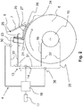
- FIG 2 shows a schematic side view of a feed device 4 according to the invention.
- the feed device 4 can be a part of the FIG Figure 1 shown card 1 or a part of a card or a cleaner.
- the feed device 4 has the feed trough 5 and the feed roller 6.
- a part of the lickerin roller 7 is also shown.
- the feed trough 5 and the feed roller 6 are arranged as open ends in an open, first circuit 31.
- the feed roller 6 is electrically connected via its axis 15. The connection is made via a first sliding contact 16.
- the first circuit 31 also includes a voltage source 13 and a current measuring device 14. If the gap between the feed trough 5 and the feed roller 6 is closed by a metal part contaminating the fiber flocks, then the first circuit 31 is also closed. A current then flows which is detected by the current measuring device 14. A current flow detected by the current measuring device 14 thus indicates a metal part between the feed trough 5 and the feed roller 6.
- the current measuring device 14 is connected to an acoustic and / or optical alarm device 17, which indicates the metal part to the operating personnel.
- the current measuring device 14 is also connected to a control device 18 which, when a metal part is detected, initializes the alarm device 17 and / or stops the feed roller 6 so that the metal part does not advance further and does not cause major damage. It is particularly advantageous if the control device 18, after it has been stopped, still rotates the feed roller 6 backwards so far that the metal part comes out from under the feed trough 5 and can easily be removed by the operating personnel.
- the feed trough 5 and the feed roller 6 must be electrically isolated from one another. This insulation can take place via an electrically insulating bearing on the axis 15 of the feed roller 6. The axis 15 of the feed roller 6 is consequently electrically isolated from the bearing and the other parts of the feed device 4.
- the feed tray 5 in the embodiment of Figure 2 has a base body 21.
- a spacer strip 23 is arranged on the base body 21 in order to enable an optimal distance between the base body 21 and an elastic lip 24.
- the spacer bar 23 is designed to be exchangeable so that it can be adapted to the respective fiber length. In the case of very short fibers, the spacer strip 23 can even be omitted entirely.
- the base body 21 can be composed of several individual parts, not shown here.
- the elastic lip 24 is arranged such that fibers can be clamped between it and the feed roller 6.
- the base body 21 is arranged on the side of the elastic lip 24 facing away from the feed roller 6.
- the elastic lip 24 can be elastically deformed at least until it touches the base body 21.
- the base body 21 prevents any further deformation of the elastic lip 24, for example due to a hard foreign body in the fiber material.
- the elastic lip 24 is therefore in particular not deformed in an area in which a permanent deformation occurs. A return of the elastic lip 24 to its original shape and position is always guaranteed.
- an easily deformable seal 27 is arranged between the elastic lip 24 and the base body 21.
- the elastic lip 24 and the base body 21 are also arranged in a third circuit 33.
- an electrical insulation 29 first isolates the elastic lip 24 from the base body 21. If the elastic lip 24 is deflected by a foreign body until it comes into contact with the base body 21, the third circuit 33 is short-circuited.
- a current measuring device 30 signals the short circuit to the control device 18.
- the electrical circuit in this exemplary embodiment is constructed in such a way that the voltage source 13 supplies a positive (+ U) and a negative (-U) voltage in addition to earth (0V).
- the amounts of the positive and negative voltage do not have to be the same and other obvious designs of the voltage source are also possible.
- the positive voltage is applied to the elastic lip 24, the negative voltage is applied to the feed roller 6 and the base body 21 of the feed trough 5 is connected to earth.
- the negative voltage (-U) is in contact with the axis 15 of the feed roller 6 via the first sliding contact 16.
- the axis 15 is connected to the feed roller 6 in an electrically conductive manner, so that if a conductive foreign body comes into contact between the base body 21 and the feed roller 6, current can flow. This current is recorded by the current measuring device 14.
- the axis 15 is also connected to a second sliding contact 35.
- the second sliding contact 35 is grounded (0V).
- current flows between the negative voltage (-U), the first sliding contact 16, the axis 15 and the second sliding contact 35 to earth (0V) in a second circuit 32.
- a current measuring device 36 measures this current flow. If this current flow is interrupted, for example due to contamination between the first sliding contact 16 and the axle 15, this can be determined by the current measuring device 36.
- the current measuring device 36 signals this state to the control device 18.
- the control device 18 can then, for example, send a signal to the alarm device 17 and / or cause the rotary movement of the feed roller 6 or card 1 to be stopped immediately.
- the measured values of the current measuring devices 14, 30 and 36 are preferably used by the control device 18 to trigger an alarm and to stop and / or retract the feed roller 6.
- the alarm can use different tones, colors or other representations to indicate in which area a metal part and / or foreign body was detected or whether a functional interruption has occurred.
- the angle by which the feed roller is retracted after a stop can also be selected as a function of the area in which the metal part or the foreign body was detected. For example, the angle for a metal part that has triggered contact between the feed roller 6 and the base body 21 of the feed trough 5 must be smaller than the angle for a foreign body which first brought the elastic lip 24 into contact with the contact surface 28 of the base body 21 Has.
Landscapes
- Engineering & Computer Science (AREA)
- Textile Engineering (AREA)
- Preliminary Treatment Of Fibers (AREA)
Abstract
Description
- Die vorliegende Erfindung betrifft eine Speisevorrichtung zur Speisung von Faserflocken in eine Spinnereivorbereitungsmaschine mit einer Speisewalze und einer Speisemulde, wobei die Speisemulde von der Speisewalze elektrisch isoliert ist, und mit einer Erkennungsvorrichtung zum Erkennen von Fremdmaterial, die einen ersten, offenen elektrischen Stromkreis aufweist, welcher mit der Speisewalze und der Speisemulde verbunden ist und der erste Stromkreis durch einen die Faserflocken verunreinigenden leitenden Fremdkörper schließbar ist und die Speisewalze mit der ersten Spannungsquelle mittels eines ersten Schleifkontakts verbunden ist sowie eine entsprechende Erkennungsvorrichtung.
- Aus der
GB 465,899 - Die
WO 2018/189595 A1 offenbart eine Speisevorrichtung, bei welcher Fremdkörper erkannt werden können. Eine Überprüfung der Einrichtung zum Erkennen der Fremdkörper auf ihre Funktionsfähigkeit hin kann nicht ohne weiteres durchgeführt werden. - Nachteilig an diesen Lösungen ist, dass zwischen die Schleifkontakte und die Rollen Schmutz gelangen kann. Dieser Schmutz kann die Schleifkontakte gegenüber den Rollen isolieren, so dass nicht mehr erkannt werden kann, wenn ein Fremdkörper die Lücke zwischen den beiden leitenden Teilen schließt.
- Aufgabe der vorliegenden Erfindung ist es somit, eine Speisevorrichtung und Erkennungsvorrichtung zu schaffen, die Fremdkörper erkennt, ohne dass die Gefahr besteht, dass auf Grund von Verschmutzung die Erkennungsvorrichtung vorhandene Fremdkörper nicht mehr erkennt und der Betrieb der Speisevorrichtung dennoch fortgesetzt wird.
- Die Aufgabe wird gelöst durch eine Speisevorrichtung mit den Merkmalen der unabhängigen Patentansprüche.
- Eine Speisevorrichtung zur Speisung von Faserflocken in eine Spinnereivorbereitungsmaschine weist eine Speisewalze und eine Speisemulde auf, wobei die Speisemulde von der Speisewalze elektrisch isoliert ist. Bei der Spinnereivorbereitungsmaschine kann es sich um eine Karde, eine Krempel oder einen Reiniger handeln. Durch die Isolierung der Speisemulde von der Speisewalze lässt sich ein offener Stromkreis bilden, bei dem die Speisemulde und die Speisewalze die offenen Enden sind.
- Der Speisevorrichtung ist eine Erkennungsvorrichtung zum Erkennen von Fremdmaterial zugeordnet, die einen ersten, offenen elektrischen Stromkreis aufweist, welcher mit der Speisewalze und der Speisemulde verbunden ist. Der erste Stromkreis ist durch einen die Faserflocken verunreinigenden leitenden Fremdkörper schließbar. Es werden also zwei sowieso schon vorhandene Elemente der Speisevorrichtung zur Detektion von Metallteilen verwendet. Weitere mechanische Teile, die den Faserfluss beeinträchtigen und gereinigt sowie gewartet werden müssen, werden nicht benötigt.
- Die Speisewalze ist mit dem ersten Stromkreis mittels eines ersten Schleifkontakts verbunden. Erfindungsgemäß weist die Erkennungsvorrichtung einen zweiten, geschlossenen elektrischen Stromkreis auf, welcher einerseits eine Kontrollleitung zur Speisewalze aufweist und andererseits mit dem ersten Schleifkontakt verbunden ist. Durch den zweiten Stromkreis wird bei ordnungsgemäßer Funktionalität der Erkennungsvorrichtung ein Strom fließen können. Sobald dieser Stromfluss unterbrochen wird, ist dies das Signal, dass zumindest einer der Kontakte, welcher mit der Speisewalze in Verbindung steht, nicht mehr ausreichend elektrisch leitfähig ist. Fremdkörper zwischen der Speisewalze und der Speisemulde können damit nicht mehr zuverlässig erkannt werden. Durch ein entsprechendes Signal können geeignete Maßnahmen ergriffen werden. Dies kann darin bestehen, dass die Spinnereivorbereitungsmaschine sofort abgestellt wird. Es kann aber auch einfach ein Hinweis im Maschinenprotokoll erzeugt werden oder ein optisches oder akustisches Signal erzeugt werden, welches den Ausfall der Erkennungsvorrichtung anzeigt. Es ist auch möglich, dass erst nach einer gewissen Zeit, in welcher das Ausfallsignal anliegt, eine entsprechende Maßnahme ergriffen wird. Damit wird verhindert, dass nicht bereits bei einer kurzzeitigen Unterbrechung zum Beispiel die Maschine abgestellt wird. Durch eine Selbstreinigung des Kontakts ist es nämlich möglich, dass nach kurzer Zeit der Kontakt wiederhergestellt ist und die Erkennungsvorrichtung wieder ordnungsgemäß arbeitet.
- Auch ist es äußert vorteilhaft, wenn die Kontrollleitung einen zweiten Schleifkontakt zu der Speisewalze aufweist. Mit dem zweiten Schleifkontakt ist eine sehr einfache Verbindung der Spannungsquelle des zweiten Stromkreises mit der Speisewalze herstellbar.
- Des Weiteren ist es vorteilhaft, wenn die Speisewalze elektrisch isoliert ist. Dies kann beispielsweise durch eine Befestigung der Speisewalze respektive deren Lager auf dem Maschinenrahmen über ein elektrisch isolierendes Bauteil. Bevorzugterweise ist das Lager der Speisewalze selbst der Isolator. So lässt sich die Isolation mit einem sehr geringen Aufwand bewerkstelligen. Besonders vorzugsweise bestehen dabei das gesamte Lager der Speisewalze und/oder ein Lagerring des Lagers aus einem elektrisch isolierenden Kunststoff. Je nach Größe der Speisewalze und den mechanischen Anforderungen kann sich eine der beiden Varianten als die vorteilhaftere erweisen.
- Besonders vorteilhaft ist es, wenn die Erkennungsvorrichtung einen dritten, offenen Stromkreis aufweist, der durch einen die Faserflocken verunreinigenden, leitenden oder nichtleitenden Fremdkörper schließbar ist. So können auch Fremdkörper erfasst werden, die nicht metallisch sind.
- Des Weiteren ist es vorteilhaft, wenn zwischen der Speisemulde und der Speisewalze eine elastische Lippe angeordnet ist, und der dritte Stromkreis mit der Speisemulde und der elastischen Lippe verbunden ist. Die elastische Lippe bildet dabei zwischen sich und der Speisewalze einen Spalt aus. Ferner weist die Speisemulde eine Kontaktfläche auf und es sind Mittel zum Erkennen eines Kontakts zwischen der elastischen Lippe und der Kontaktfläche vorgesehen. Wird die elastische Lippe durch einen Fremdkörper deformiert, dann kommt sie, sofern der Fremdkörper und damit die elastische Deformation groß genug sind, in Kontakt mit der Speisemulde bzw. der Kontaktfläche. Durch die Mittel zum Erkennen eines Kontakts werden der Kontakt und damit auch der Fremdkörper erkannt. Durch den Kontakt der elastischen Lippe mit der Speisemulde werden also auch nichtmetallische Fremdkörper erkannt.
- Vorteilhaft ist es zudem, wenn zwischen der Speisemulde und der elastischen Lippe eine Dichtung angeordnet ist. Die elastische Lippe und die Kontaktfläche an der Speisemulde bilden eine Öffnung zu einem Hohlraum, der unter anderem die Beweglichkeit der elastischen Lippe ermöglicht. Damit dieser Hohlraum nicht verschmutzt, ist vorteilhafterweise zwischen der elastischen Lippe und der Kontaktfläche eine Dichtung angeordnet. Diese Dichtung ist dabei so weit verformbar, dass sie bei einer Verformung der elastischen Lippe überdrückt werden kann und somit den elektrischen Kontakt nicht behindert.
- Vorteile bringt es zudem mit sich, wenn die elastische Lippe aus leitendem Material besteht. Es ist auch vorteilhaft, wenn die elastische Lippe aus Stahl, insbesondere aus Chromstahl, besteht, da diese Werkstoffe gute Elastizität bei einer guten Federstärke aufweisen. Chromstahl ist darüber hinaus auch noch korrosionsbeständig. Eine Wandstärke der elastischen Lippe an ihrem vorderen Ende liegt dabei bevorzugt zwischen 1,5 mm und 2 mm, da dies die notwendige Federstärke liefert.
- Vorteilhaft ist es, wenn die Erkennungsvorrichtung eine akustische und/oder optische Alarmeinrichtung umfasst, die ausgelöst wird, wenn der erste Stromkreis zwischen der Speisewalze und der Speisemulde und/oder der dritte Stromkreis zwischen der elastischen Lippe und der Speisemulde geschlossen wird und/oder der zweite Stromkreis geöffnet wird. Der Alarm wird also ausgelöst, wenn ein die Faserflocken verunreinigendes Metallteil und/oder ein anderer Fremdkörper detektiert werden. Dadurch wird das Bedienpersonal auf das Metallteil bzw. auf den Fremdkörper aufmerksam gemacht. Das Bedienpersonal kann daraufhin die Produktion stoppen und/oder das Metallteil bzw. den Fremdkörper entfernen. Der Alarm wird aber auch ausgelöst, wenn der zweite Stromkreis geöffnet wird. Dies bedeutet, dass kein Kontakt mehr zwischen den Leitungen von der Stromquelle zu der Speisewalze vorhanden ist. Dies kann zum Beispiel erfolgen, wenn zwischen einem der Schleifkontakte und der Speisewalze eine Verschmutzung auftritt, welche eine Isolierschicht bildet. Die elektrische Verbindung wird dadurch unterbrochen und die Alarmeinrichtung wird ausgelöst.
- Vorteilhaft ist es zudem, wenn die Speisevorrichtung eine Steuereinrichtung umfasst, die bei einem geschlossenen ersten und/oder dritten Stromkreis und/oder bei einem offenen zweiten Stromkreis die Drehung der Speisewalze anhält. Bei modernen Speisevorrichtungen ist es möglich, dass sich die Oberfläche der Speisewalze vom Zeitpunkt des Erkennens eines Metallteils bzw. Fremdkörpers bzw. der Unterbrechung der Kontaktfähigkeit der Speisewalze bis zum Stillstand lediglich 10 mm weiterbewegt. So können Beschädigungen der Speisewalze und der Speisemulde weitgehend vermieden werden. Vorzugsweise kann die Steuereinrichtung, nachdem die Speisewalze zum Stillstand gekommen ist, diese um einen vorgegebenen oder vorgebbaren Winkel zurückdrehen. Dabei ist bzw. wird dieser Winkel so eingestellt, dass das Metallteil bzw. der Fremdkörper in einen Bereich gelangt, aus dem er durch das Bedienpersonal leicht entfernt werden kann. Auf das Zurückdrehen kann verzichtet werden, wenn der Stillstand aufgrund einer Unterbrechung der Kontaktfähigkeit der Speisewalze erfolgt ist.
- Eine erfindungsgemäße Erkennungsvorrichtung zum Erkennen von Fremdmaterial in einer Speisevorrichtung weist einen ersten, offenen elektrischen Stromkreis auf, welcher mit der Speisewalze und der Speisemulde verbindbar ist. Der erste Stromkreis ist durch einen die Faserflocken verunreinigenden, leitenden Fremdkörper schließbar. Die Erkennungsvorrichtung weist einen ersten Schleifkontakt auf zur Verbindung der ersten Spannungsquelle mit der Speisewalze. Ebenso weist die Erkennungsvorrichtung einen zweiten, geschlossenen elektrischen Stromkreis auf, welcher einerseits eine Kontrollleitung zur Verbindung mit der Speisewalze und andererseits eine Verbindung mit dem ersten Schleifkontakt hat. Durch den zweiten, geschlossenen elektrischen Stromkreis kann überprüft werden, ob die Erkennungsvorrichtung funktionsfähig ist. Sobald der Stromkreis geöffnet, also unterbrochen ist, zeigt dies an, dass die Erkennungsvorrichtung keinen Kontakt mehr zur Speisewalze hat. Eine entsprechende Maßnahme ist sodann zu ergreifen. Mit dem zweiten, geschlossenen elektrischen Stromkreis ist es auf besonders einfache Weise möglich, dass die Erkennungsvorrichtung fehlerfrei arbeiten kann bzw. bei Auftreten eines Fehlers die Speisevorrichtung oder die Spinnereivorbereitungsmaschine gestoppt werden, um eine Beschädigung der Maschine zu vermeiden.
- Besondere Vorteile bringt es mit sich, wenn die Erkennungsvorrichtung einen dritten, offenen Stromkreis aufweist, der durch einen die Faserflocken verunreinigenden, leitenden oder nichtleitenden Fremdkörper schließbar ist. Damit können nicht nur metallische Fremdkörper, sondern auch nichtmetallische Fremdkörper erfasst werden.
- Vorteile bringt es zudem mit sich, wenn die Erkennungsvorrichtung eine akustische und/oder optische Alarmeinrichtung umfasst, die ausgelöst wird, wenn der erste Stromkreis zwischen der Speisewalze und der Speisemulde und/oder der dritte Stromkreis zwischen der Speisemulde und der elastischen Lippe geschlossen wird und/oder der zweite Stromkreis geöffnet wird. Jedes dieser Ereignisse deutet auf einen Zustand hin, welcher entweder signalisiert werden muss oder bei welchem sogar eine Maßnahme ergriffen werden muss, um eine Beschädigung der Maschine zu vermeiden.
- Die Speisevorrichtung und die Erkennungsvorrichtung sind gemäß der vorangegangenen Beschreibung ausgebildet, wobei die genannten Merkmale einzeln oder in beliebiger Kombination vorhanden sein können.
- Weitere Vorteile der Erfindung sind in den nachfolgenden Ausführungsbeispielen beschrieben. Es zeigt:
- Figur 1
- eine schematische Seitenansicht einer Karde und
- Figur 2
- eine schematische Seitenansicht einer Speisevorrichtung mit einer Erken-nungsvorrichtung.
- Bei der nachfolgenden Beschreibung alternativer Ausführungsbeispiele werden für Merkmale, die im Vergleich zu anderen Ausführungsbeispielen in ihrer Ausgestaltung und/oder Wirkweise identisch und/oder zumindest vergleichbar sind, gleiche Bezugszeichen verwendet. Sofern diese nicht nochmals detailliert erläutert werden, entspricht deren Ausgestaltung und/oder Wirkweise der Ausgestaltung und Wirkweise der vorstehend bereits beschriebenen Merkmale.
-
Figur 1 zeigt eine schematische Seitenansicht einer Karde 1. Dabei werden die Fasern in der Karde 1 von links nach rechts transportiert. Eine Fasermatte 2 läuft zunächst über eine Zufuhrplatte 3 und gelangt dann in eine Speisevorrichtung 4. Die Speisevorrichtung 4 weist eine Speisemulde 5 auf, die mit einer Speisewalze 6 zusammenwirkt. Die zwischen Speisemulde 5 und Speisewalze 6 geklemmte Fasermatte 2 wird sodann einer Vorreisserwalze 7 zugespeist. - Von der Vorreisserwalze 7 geht das Faservlies weiter auf einen Tambour 8 und wird zwischen dem Tambour 8 und einem hier sehr schematisch dargestellten Deckel 9 weiterverarbeitet. Das Faservlies wird sodann von einer Dofferwalze 10 abgenommen und an eine Verdichtungseinheit 11 weitergeleitet, wo es zu einem Kardenband 12 verdichtet wird.
-
Figur 2 zeigt eine schematische Seitenansicht einer erfindungsgemäßen Speisevorrichtung 4. Die Speisevorrichtung 4 kann ein Teil der inFigur 1 gezeigten Karde 1 oder aber auch ein Teil einer Krempel oder eines Reinigers sein. Die Speisevorrichtung 4 weist dabei die Speisemulde 5 und die Speisewalze 6 auf. Außerdem ist noch ein Teil der Vorreisserwalze 7 gezeigt. - Die Speisemulde 5 und die Speisewalze 6 sind als offene Enden in einem offenen, ersten Stromkreis 31 angeordnet. Dabei ist die Speisewalze 6 über ihre Achse 15 elektrisch angeschlossen. Die Verbindung erfolgt über einen ersten Schleifkontakt 16. Der erste Stromkreis 31 umfasst des Weiteren eine Spannungsquelle 13 und eine Strommesseinrichtung 14. Wird die Lücke zwischen der Speisemulde 5 und der Speisewalze 6 durch ein die Faserflocken verunreinigendes Metallteil geschlossen, dann wird auch der erste Stromkreis 31 geschlossen. Es fließt daraufhin ein Strom, der von der Strommesseinrichtung 14 detektiert wird. Ein von der Strommesseinrichtung 14 detektierter Stromfluss zeigt also ein Metallteil zwischen der Speisemulde 5 und der Speisewalze 6 an.
- Um den Stromfluss im ersten Stromkreis 31 und damit die Detektion des Metallteils anzuzeigen, ist die Strommesseinrichtung 14 mit einer akustischen und/oder optischen Alarmeinrichtung 17 verbunden, der dem Bedienpersonal das Metallteil anzeigt.
- Vorteilhafterweise ist die Strommesseinrichtung 14 darüber hinaus mit einer Steuereinrichtung 18 verbunden, die bei der Detektion eines Metallteils die Alarmeinrichtung 17 initialisiert und/oder die Speisewalze 6 stoppt, damit das Metallteil nicht weiter vordringt und keine größeren Beschädigungen verursacht. Besonders vorteilhaft ist es, wenn die Steuereinrichtung 18 die Speisewalze 6, nachdem sie gestoppt wurde, noch so weit rückwärts dreht, dass das Metallteil unter der Speisemulde 5 herauskommt und einfach vom Bedienpersonal entfernt werden kann.
- Um den ersten Stromkreis 31 offen zu halten, müssen die Speisemulde 5 und die Speisewalze 6 voneinander elektrisch isoliert sein. Diese Isolation kann über ein elektrisch isolierendes Lager der Achse 15 der Speisewalze 6 erfolgen. Die Achse 15 der Speisewalze 6 ist folglich vom Lager und den anderen Teilen der Speisevorrichtung 4 elektrisch isoliert.
- Die Speisemulde 5 im Ausführungsbeispiel der
Figur 2 weist einen Grundkörper 21 auf. Am Grundkörper 21 ist eine Distanzleiste 23 angeordnet, um einen optimalen Abstand zwischen dem Grundkörper 21 und einer elastischen Lippe 24 zu ermöglichen. Die Distanzleiste 23 ist austauschbar ausgebildet, so dass sie an die jeweilige Faserlänge angepasst werden kann. Bei sehr kurzen Fasern kann die Distanzleiste 23 sogar ganz weggelassen werden. Der Grundkörper 21 kann aus mehreren, hier nicht dargestellten Einzelteilen zusammengesetzt sein. - Die elastische Lippe 24 ist so angeordnet, dass Fasern zwischen ihr und der Speisewalze 6 geklemmt werden können. Auf der der Speisewalze 6 abgewandten Seite der elastischen Lippe 24 ist der Grundkörper 21 angeordnet. Dabei kann die elastische Lippe 24 mindestens so weit elastisch verformt werden, bis sie den Grundkörper 21 berührt. Durch den Grundkörper 21 ist eine weitere Verformung der elastischen Lippe 24, beispielsweise durch einen harten Fremdkörper im Fasermaterial, ausgeschlossen. Die elastische Lippe 24 wird also insbesondere nicht in einen Bereich verformt, in dem eine permanente Verformung eintritt. Eine Rückkehr der elastischen Lippe 24 in ihre ursprüngliche Form und Position ist dadurch stets gewährleistet.
- Um einen Zwischenraum 26 zwischen der elastischen Lippe 24 und dem Grundkörper 21 vor Verschmutzung, insbesondere durch Faserflug, zu schützen, ist zwischen der elastischen Lippe 24 und dem Grundkörper 21 eine leicht verformbare Dichtung 27 angeordnet.
- Um einen harten Fremdkörper zu detektieren, der die elastische Lippe 24 gegen eine Kontaktfläche 28 des Grundkörpers 21 drückt, sind auch die elastische Lippe 24 und der Grundkörper 21 in einem dritten Stromkreis 33 angeordnet. Dazu isoliert zunächst eine elektrische Isolation 29 die elastische Lippe 24 von dem Grundkörper 21. Wird die elastische Lippe 24 durch einen Fremdkörper bis zu einem Kontakt mit dem Grundkörper 21 ausgelenkt, so wird der dritte Stromkreis 33 kurzgeschlossen. Eine Strommesseinrichtung 30 signalisiert den Kurzschluss an die Steuereinrichtung 18.
- Die elektrische Schaltung in diesem Ausführungsbeispiel ist so aufgebaut, dass die Spannungsquelle 13 neben der Erde (0V) eine positive (+U) und eine negative (-U) Spannung liefert. Dabei müssen die Beträge der positiven und der negativen Spannung nicht gleich sein und auch andere naheliegende Auslegungen der Spannungsquelle sind möglich. Die positive Spannung liegt dabei an der elastischen Lippe 24 an, die negative Spannung liegt an der Speisewalze 6 an und der Grundkörper 21 der Speisemulde 5 ist mit der Erde verbunden.
- Ein die Faserflocken verunreinigendes Metallteil, das die Speisemulde 5 mit der Speisewalze 6 in Kontakt bringt, schließt, wie oben beschrieben, den ersten Stromkreis 31 und der Stromfluss wird von der Strommesseinrichtung 14 detektiert. Wird hingegen die elastische Lippe 24, beispielsweise durch einen harten Fremdkörper, soweit verformt, dass sie die Kontaktfläche 28 des Grundkörpers 21 berührt, dann wird ein anderer, dritter Stromkreis 33 geschlossen und es fließt Strom, den die weitere Strommesseinrichtung 30 misst. Auch ein kleineres Metallteil, das zwar noch keinen Kontakt zwischen der Speisewalze 6 und dem Grundkörper 21 der Speisemulde 5 herstellen konnte, jedoch einen Kontakt zwischen der Speisewalze 6 und der elastischen Lippe 24 herstellt, kann detektiert werden. Es werden dabei die beiden Stromkreise 31 und 33 geschlossen. Dies hat einen Stromfluss durch die Strommesseinrichtung 14 und die weitere Strommesseinrichtung 30 zur Folge. Ein Stromfluss durch die beiden Strommesseinrichtungen 14 und 30 indiziert folglich einen leitenden Fremdkörper zwischen der Speisewalze 6 und der elastischen Lippe 24.
- In dem vorliegenden Ausführungsbeispiel steht die negative Spannung (-U) über den ersten Schleifkontakt 16 mit der Achse 15 der Speisewalze 6 in Kontakt. Die Achse 15 ist elektrisch leitend mit der Speisewalze 6 verbunden, sodass bei einem Kontakt eines leitenden Fremdkörpers zwischen dem Grundkörper 21 und der Speisewalze 6 Strom fliessen kann. Dieser Strom wird von der Strommesseinrichtung 14 erfasst.
- Die Achse 15 ist weiterhin mit einem zweiten Schleifkontakt 35 verbunden. Der zweite Schleifkontakt 35 ist geerdet (0V). Im funktionsfähigen Betrieb der Einrichtung fließt damit Strom zwischen der negativen Spannung (-U), dem ersten Schleifkontakt 16, der Achse 15 und dem zweiten Schleifkontakt 35 zur Erde (0V) in einem zweiten Stromkreis 32. Eine Strommesseinrichtung 36 misst diesen Stromfluss. Sollte dieser Stromfluss unterbrochen sein, beispielsweise durch eine Verschmutzung zwischen dem ersten Schleifkontakt 16 und der Achse 15, so kann dies durch die Strommesseinrichtung 36 festgestellt werden. Die Strommesseinrichtung 36 signalisiert diesen Zustand an die Steuereinrichtung 18. Die Steuereinrichtung 18 kann sodann beispielsweise ein Signal an die Alarmeinrichtung 17 geben und/oder ein sofortiges Abstellen der Drehbewegung der Speisewalze 6 bzw. der Karde 1 bewirken.
- Mit dieser Einrichtung ist es möglich, dass eine Fehlfunktion der Erkennungsvorrichtung rechtzeitig vor einer Beschädigung der Karde 1 festgestellt werden kann. Die Abstellung der Speisewalze 6 bzw. der Karde 1 kann unmittelbar nach Ermittlung der Kontaktunterbrechung erfolgen. Es kann aber auch vorteilhaft sein, erst dann die Drehung der Speisewalze 6 bzw. die Karde 1 abzustellen, wenn diese Unterbrechung über einen längeren, vorgebbaren Zeitraum erfolgt. Damit wird vermieden, dass bereits bei einer kurzzeitigen Unterbrechung, beispielsweise, wenn Staub zwischen dem Schleifkontakt 16 oder 35 und der Achse 15 gelangt, dieser sich aber nach kurzer Zeit wieder löst, der Betrieb der Speisewalze 6 und der Karde 1 unterbrochen wird, obwohl die Störung schnell selbst behoben wurde.
- Vorzugsweise werden die Messwerte der Strommesseinrichtungen 14, 30 und 36 zum Auslösen eines Alarms und zum Stoppen und/oder Zurückfahren der Speisewalze 6 durch die Steuereinrichtung 18 herangezogen. So kann der Alarm, beispielsweise durch unterschiedliche Töne, Farben oder andere Darstellungen, anzeigen, in welchem Bereich ein Metallteil und/oder Fremdkörper detektiert wurde oder ob eine Funktionsunterbrechung vorliegt. Auch kann der Winkel, um den die Speisewalze nach einem Stopp zurückgefahren wird, in Abhängigkeit vom Bereich, in dem das Metallteil bzw. der Fremdkörper detektiert wurde, gewählt werden. Beispielsweise muss der Winkel für ein Metallteil, das einen Kontakt zwischen der Speisewalze 6 und dem Grundkörper 21 der Speisemulde 5 ausgelöst hat, kleiner sein als der Winkel für einen Fremdkörper, der erst die elastische Lippe 24 mit der Kontaktfläche 28 des Grundkörpers 21 in Kontakt gebracht hat.
- Die vorliegende Erfindung ist nicht auf die dargestellten und beschriebenen Ausführungsbeispiele beschränkt. Abwandlungen im Rahmen der Patentansprüche sind ebenso möglich wie eine Kombination der Merkmale, auch wenn diese in unterschiedlichen Ausführungsbeispielen dargestellt und beschrieben sind.
-
- 1
- Karde
- 2
- Fasermatte
- 3
- Zufuhrplatte
- 4
- Speisevorrichtung
- 5
- Speisemulde
- 6
- Speisewalze
- 7
- Vorreisserwalze
- 8
- Tambour
- 9
- Deckel
- 10
- Dofferwalze
- 11
- Verdichtungseinheit
- 12
- Kardenband
- 13
- Spannungsquelle
- 14
- Strommesseinrichtung
- 15
- Achse
- 16
- Erster Schleifkontakt
- 17
- Alarmeinrichtung
- 18
- Steuereinrichtung
- 21
- Grundkörper
- 23
- Distanzleiste
- 24
- Elastische Lippe
- 26
- Zwischenraum
- 27
- Dichtung
- 28
- Kontaktfläche
- 29
- Isolation
- 30
- Strommesseinrichtung
- 31
- Erster Stromkreis
- 32
- Zweiter Stromkreis
- 33
- Dritter Stromkreis
- 35
- Zweiter Schleifkontakt
- 36
- Strommesseinrichtung
Claims (13)
- Speisevorrichtung zur Speisung von Faserflocken in eine Spinnereivorbereitungsmaschine,- mit einer Speisewalze (6) und- einer Speisemulde (5),- wobei die Speisemulde (5) von der Speisewalze (6) elektrisch isoliert ist und- mit einer Erkennungsvorrichtung zum Erkennen von Fremdmaterial,- die einen ersten, offenen elektrischen Stromkreis (31) aufweist,- welcher mit der Speisewalze (6) und der Speisemulde (5) verbunden ist und- der erste Stromkreis (31) durch einen die Faserflocken verunreinigenden leitenden Fremdkörper schließbar ist und- die Speisewalze (6) mit dem ersten Stromkreis (31) mittels eines ersten Schleifkontakts (16) verbunden ist,dadurch gekennzeichnet,- dass die Erkennungsvorrichtung einen zweiten, geschlossenen elektrischen Stromkreis (32) aufweist, welcher- einerseits eine Kontrollleitung zur Speisewalze (6) aufweist und- andererseits mit dem ersten Schleifkontakt (16) verbunden ist.
- Speisevorrichtung nach dem vorherigen Anspruch, dadurch gekennzeichnet, dass die Kontrollleitung einen zweiten Schleifkontakt (35) zu der Speisewalze (6) aufweist.
- Speisevorrichtung nach einem der vorherigen Ansprüche, dadurch gekennzeichnet, dass die Speisewalze (6) elektrisch isoliert ist.
- Speisevorrichtung nach einem der vorherigen Ansprüche, dadurch gekennzeichnet, dass das Lager der Speisewalze (6) der Isolator ist.
- Speisevorrichtung nach einem der vorherigen Ansprüche, dadurch gekennzeichnet, dass die Erkennungsvorrichtung einen dritten, offenen Stromkreis (33) aufweist, der durch einen die Faserflocken verunreinigenden, leitenden oder nichtleitenden Fremdkörper schließbar ist.
- Speisevorrichtung nach einem der vorherigen Ansprüche, dadurch gekennzeichnet, dass zwischen der Speisemulde (5) und der Speisewalze (6) eine elastische Lippe (24) angeordnet ist, und der dritte Stromkreis (33) mit der Speisemulde (5) und der elastischen Lippe (24) verbunden ist.
- Speisevorrichtung nach einem der vorherigen Ansprüche, dadurch gekennzeichnet, dass zwischen der Speisemulde (5) und der elastischen Lippe (24) eine Dichtung (27) angeordnet ist.
- Speisevorrichtung nach einem der vorherigen Ansprüche, dadurch gekennzeichnet, dass die elastische Lippe (24) aus leitendem Material, insbesondere aus Chromstahl, besteht.
- Speisevorrichtung nach einem der vorherigen Ansprüche, dadurch gekennzeichnet, dass die Erkennungsvorrichtung eine akustische und/oder optische Alarmeinrichtung (17) umfasst, die ausgelöst wird, wenn der erste Stromkreis (31) zwischen der Speisewalze (6) und der Speisemulde (5) und/oder dritte Stromkreis (33) zwischen der Speisemulde (5) und der elastischen Lippe (24) geschlossen wird und/oder der zweite Stromkreis (32) geöffnet wird.
- Speisevorrichtung nach einem der vorherigen Ansprüche, dadurch gekennzeichnet, dass die Speisevorrichtung (4) eine Steuereinrichtung (18) umfasst, die- bei einem geschlossenen ersten und/oder dritten Stromkreis (31, 33) und/oder- bei einem offenen zweiten Stromkreis (32)die Drehung der Speisewalze (6) anhält.
- Erkennungsvorrichtung zum Erkennen von Fremdmaterial in einer Speisevorrichtung (4) nach einem der vorherigen Ansprüche,- die einen ersten, offenen elektrischen Stromkreis (31) aufweist,- welcher mit der Speisewalze (6) und der Speisemulde (5) verbindbar ist und- der erste Stromkreis (31) durch einen die Faserflocken verunreinigenden, leitenden Fremdkörper schließbar ist und- die Erkennungsvorrichtung einen ersten Schleifkontakt (16) aufweist zur Verbindung einer Spannungsquelle (13) mit der Speisewalze (6),dadurch gekennzeichnet,- dass die Erkennungsvorrichtung einen zweiten, geschlossenen elektrischen Stromkreis (32) aufweist, welcher- einerseits eine Kontrollleitung zur Verbindung mit der Speisewalze (6) und- andererseits eine Verbindung mit dem ersten Schleifkontakt (16) aufweist.
- Erkennungsvorrichtung nach dem vorherigen Anspruch, dadurch gekennzeichnet, dass die Erkennungsvorrichtung einen dritten, offenen Stromkreis (33) aufweist, der durch einen die Faserflocken verunreinigenden, leitenden oder nichtleitenden Fremdkörper schließbar ist.
- Erkennungsvorrichtung nach einem der Ansprüche 11 oder 12, dadurch gekennzeichnet, dass die Erkennungsvorrichtung eine akustische und/oder optische Alarmeinrichtung (17) umfasst, die ausgelöst wird, wenn der erste Stromkreis (31) zwischen der Speisewalze (6) und der Speisemulde (5) und/oder der dritte Stromkreis (33) zwischen der Speisemulde (5) und der elastischen Lippe (24) geschlossen wird und/oder der zweite Stromkreis (32) geöffnet wird.
Applications Claiming Priority (1)
| Application Number | Priority Date | Filing Date | Title |
|---|---|---|---|
| CH00792/19A CH716307A1 (de) | 2019-06-12 | 2019-06-12 | Speisevorrichtung zur Speisung von Faserflocken in eine Spinnereivorbereitungsmaschine mit einer Erkennungsvorrichtung zum Erkennen von Fremdmaterial. |
Publications (2)
| Publication Number | Publication Date |
|---|---|
| EP3751026A1 true EP3751026A1 (de) | 2020-12-16 |
| EP3751026B1 EP3751026B1 (de) | 2024-11-20 |
Family
ID=70977771
Family Applications (1)
| Application Number | Title | Priority Date | Filing Date |
|---|---|---|---|
| EP20178197.8A Active EP3751026B1 (de) | 2019-06-12 | 2020-06-04 | Speisevorrichtung |
Country Status (3)
| Country | Link |
|---|---|
| EP (1) | EP3751026B1 (de) |
| CN (1) | CN112080820B (de) |
| CH (1) | CH716307A1 (de) |
Families Citing this family (2)
| Publication number | Priority date | Publication date | Assignee | Title |
|---|---|---|---|---|
| CN113046867A (zh) * | 2020-12-28 | 2021-06-29 | 安洁利德科技(江苏)有限公司 | 无纺布梳理机滚轮防打坏装置 |
| CN114622308A (zh) * | 2022-03-14 | 2022-06-14 | 王陶 | 一种基于人工智能的纺织过程自适应清棉系统 |
Citations (3)
| Publication number | Priority date | Publication date | Assignee | Title |
|---|---|---|---|---|
| GB465899A (en) | 1935-12-06 | 1937-05-19 | Thomas Merchant | An electrically controlled stop-motion device for detecting metallic substances in fibrous materials and stopping its passage into process machinery, such as scutching, opening, carding, scribbling and like machines |
| US3092875A (en) * | 1959-11-03 | 1963-06-11 | Cocker Machine & Foundry Compa | Stop motion mechanism |
| CH713692A1 (de) * | 2017-04-13 | 2018-10-15 | Rieter Ag Maschf | Speisevorrichtung. |
Family Cites Families (12)
| Publication number | Priority date | Publication date | Assignee | Title |
|---|---|---|---|---|
| SU848490A1 (ru) * | 1979-10-24 | 1981-07-23 | Костромской технологический институт | Устройство дл получени фасонной нити |
| DE3912115A1 (de) * | 1989-04-13 | 1990-10-18 | Hollingsworth Gmbh | Reinigungsvorrichtung fuer textilfasern |
| FR2754482B1 (fr) * | 1996-10-14 | 1998-12-18 | Ona Electro Erosion | Procede et dispositif de coupe et d'enfilage automatique pour machine d'electroerosion |
| EP1215312A1 (de) * | 2000-12-18 | 2002-06-19 | Maschinenfabrik Rieter Ag | Online Messtechnik |
| DE102006002812B4 (de) * | 2006-01-19 | 2021-10-07 | Trützschler GmbH & Co Kommanditgesellschaft | Vorrichtung an einer Spinnereivorbereitungsmaschine, insbesondere Karde, Krempel o. dgl., zur Überwachung und/oder Einstellung von Abständen an Bauteilen |
| KR100694585B1 (ko) * | 2006-04-19 | 2007-03-14 | 장중원 | 섬유제조라인의 금속성 물질 감지장치 |
| DE102007026464A1 (de) * | 2007-06-05 | 2008-12-11 | TRüTZSCHLER GMBH & CO. KG | Vorrichtung zum Erkennen von störenden Partikeln, insbesondere Trashteilen, Nissen, Schalennissen, Noppen u. dgl., in textilem Fasergut, z.B. Baumwolle, Chemiefasern u.dgl., namentlich an Spinnereivorbereitungsmaschinen |
| DE102008008210B4 (de) * | 2007-12-06 | 2013-07-18 | Sipra Patententwicklungs- Und Beteiligungsgesellschaft Mbh | Verfahren und Rundstrickmaschine zur Herstellung einer Maschenware aus einem ungedrehten Fasermaterial |
| CN201592303U (zh) * | 2009-12-04 | 2010-09-29 | 上海广为电器工具有限公司 | 具有双电源电压系统的逆变直流电焊机 |
| CN204198933U (zh) * | 2014-11-05 | 2015-03-11 | 山东德润新材料科技有限公司 | 一种无纺布梳理机喂入系统金属探测装置 |
| CN106921324B (zh) * | 2017-03-10 | 2020-08-14 | 深圳市杰美康机电有限公司 | 一种混合式步进电机的参数辨识方法 |
| CN206956233U (zh) * | 2017-07-04 | 2018-02-02 | 际华三五四二纺织有限公司 | 成卷机棉层非棉纤维荧光检测装置 |
-
2019
- 2019-06-12 CH CH00792/19A patent/CH716307A1/de not_active Application Discontinuation
-
2020
- 2020-06-04 EP EP20178197.8A patent/EP3751026B1/de active Active
- 2020-06-11 CN CN202010528986.5A patent/CN112080820B/zh active Active
Patent Citations (4)
| Publication number | Priority date | Publication date | Assignee | Title |
|---|---|---|---|---|
| GB465899A (en) | 1935-12-06 | 1937-05-19 | Thomas Merchant | An electrically controlled stop-motion device for detecting metallic substances in fibrous materials and stopping its passage into process machinery, such as scutching, opening, carding, scribbling and like machines |
| US3092875A (en) * | 1959-11-03 | 1963-06-11 | Cocker Machine & Foundry Compa | Stop motion mechanism |
| CH713692A1 (de) * | 2017-04-13 | 2018-10-15 | Rieter Ag Maschf | Speisevorrichtung. |
| WO2018189595A1 (de) | 2017-04-13 | 2018-10-18 | Maschinenfabrik Rieter Ag | Speisevorrichtung |
Also Published As
| Publication number | Publication date |
|---|---|
| EP3751026B1 (de) | 2024-11-20 |
| CN112080820A (zh) | 2020-12-15 |
| CN112080820B (zh) | 2024-02-23 |
| CH716307A1 (de) | 2020-12-15 |
Similar Documents
| Publication | Publication Date | Title |
|---|---|---|
| EP3751026B1 (de) | Speisevorrichtung | |
| DE2714353A1 (de) | Textilmaschine mit vorrichtungen zum erfassen der querdimension des laufenden garns | |
| EP3795054B1 (de) | Bodenreinigungsmaschine mit einer kehreinrichtung mit einem kehrgutbehälter mit füllstandsdetektionseinrichtung | |
| DE102006002812B4 (de) | Vorrichtung an einer Spinnereivorbereitungsmaschine, insbesondere Karde, Krempel o. dgl., zur Überwachung und/oder Einstellung von Abständen an Bauteilen | |
| DE10296651B4 (de) | Verfahren zum Überwachen des Betriebs einer Schaberbaugruppe in einer Papiermaschine und Schaberbaugruppe zum Ausführen dieses Verfahrens | |
| EP2743385B1 (de) | Verfahren und Vorrichtung zum Überwachen von Kontakten eines sich drehenden Bauteils einer Textilmaschine | |
| DE10121008B4 (de) | Kapazitive Tastatur mit Auswerteschaltung | |
| EP3610058B1 (de) | Speisevorrichtung | |
| EP3610059B1 (de) | Speisemulde und speisevorrichtung | |
| DE102014110106B4 (de) | Vorrichtung und Verfahren zum Ermitteln des Zustandes der Messer an einer Faserschneidvorrichtung | |
| EP3959363B1 (de) | Karde | |
| DE2435936A1 (de) | Vorrichtung zum stillsetzen einer webmaschine bei kettfadenbruch | |
| EP3610060B1 (de) | Speisemulde und speisevorrichtung mit einer speisemulde | |
| DE102016117302A1 (de) | Verfahren zum Betreiben einer Textilmaschine und Textilmaschine | |
| EP0457754B1 (de) | Weichenantrieb | |
| DE102018109900A1 (de) | Arbeitsstelle einer Spinn- oder Spulmaschine sowie Verfahren zum Betreiben einer Arbeitsstelle für eine Spinn- oder Spulmaschine | |
| DE102021120662A1 (de) | Streckwerk einer Spinnereimaschine sowie Verfahren zum vorbeugenden Erkennen eines Maschinenstillstands in einem solchen Streckwerk | |
| EP3959365A1 (de) | Vorrichtung und verfahren zur einstellung mindestens eines flexibelbogens konzentrisch zu einer drehbar gelagerten garnierten trommel einer karde | |
| AT526661B1 (de) | Bahnstabilisator und verfahren zur ausbildung eines unterdrucks | |
| DE102019106702A1 (de) | Bahnbeobachtungssystem und Verfahren zur Bahnbeobachtung | |
| DE102011050919A1 (de) | Überwachungsvorrichtung an einer Spinnmaschine | |
| DE102019204835B4 (de) | Formteilmaschine, Maschinensystem, Verwendung eines Kontaktelements und Verfahren zum Betreiben eines Maschinensystems | |
| DE2832520A1 (de) | Vorrichtung zum entfernen der restanoden von anodenstangen | |
| DE1083895B (de) | Einrichtung zur gegenseitig lagerichtigen Fixierung von axial hintereinander angeordneten Baueinheiten eines elektrischen Schalters od. dgl. | |
| DE1166669B (de) | Reinigungseinrichtung an Streckwerken von Spinnereimaschinen |
Legal Events
| Date | Code | Title | Description |
|---|---|---|---|
| PUAI | Public reference made under article 153(3) epc to a published international application that has entered the european phase |
Free format text: ORIGINAL CODE: 0009012 |
|
| STAA | Information on the status of an ep patent application or granted ep patent |
Free format text: STATUS: THE APPLICATION HAS BEEN PUBLISHED |
|
| AK | Designated contracting states |
Kind code of ref document: A1 Designated state(s): AL AT BE BG CH CY CZ DE DK EE ES FI FR GB GR HR HU IE IS IT LI LT LU LV MC MK MT NL NO PL PT RO RS SE SI SK SM TR |
|
| AX | Request for extension of the european patent |
Extension state: BA ME |
|
| STAA | Information on the status of an ep patent application or granted ep patent |
Free format text: STATUS: REQUEST FOR EXAMINATION WAS MADE |
|
| 17P | Request for examination filed |
Effective date: 20210531 |
|
| RBV | Designated contracting states (corrected) |
Designated state(s): AL AT BE BG CH CY CZ DE DK EE ES FI FR GB GR HR HU IE IS IT LI LT LU LV MC MK MT NL NO PL PT RO RS SE SI SK SM TR |
|
| STAA | Information on the status of an ep patent application or granted ep patent |
Free format text: STATUS: EXAMINATION IS IN PROGRESS |
|
| 17Q | First examination report despatched |
Effective date: 20220824 |
|
| P01 | Opt-out of the competence of the unified patent court (upc) registered |
Effective date: 20230519 |
|
| GRAP | Despatch of communication of intention to grant a patent |
Free format text: ORIGINAL CODE: EPIDOSNIGR1 |
|
| STAA | Information on the status of an ep patent application or granted ep patent |
Free format text: STATUS: GRANT OF PATENT IS INTENDED |
|
| INTG | Intention to grant announced |
Effective date: 20240701 |
|
| RAP3 | Party data changed (applicant data changed or rights of an application transferred) |
Owner name: RIETER AG |
|
| GRAS | Grant fee paid |
Free format text: ORIGINAL CODE: EPIDOSNIGR3 |
|
| GRAA | (expected) grant |
Free format text: ORIGINAL CODE: 0009210 |
|
| STAA | Information on the status of an ep patent application or granted ep patent |
Free format text: STATUS: THE PATENT HAS BEEN GRANTED |
|
| AK | Designated contracting states |
Kind code of ref document: B1 Designated state(s): AL AT BE BG CH CY CZ DE DK EE ES FI FR GB GR HR HU IE IS IT LI LT LU LV MC MK MT NL NO PL PT RO RS SE SI SK SM TR |
|
| REG | Reference to a national code |
Ref country code: GB Ref legal event code: FG4D Free format text: NOT ENGLISH |
|
| REG | Reference to a national code |
Ref country code: CH Ref legal event code: EP |
|
| REG | Reference to a national code |
Ref country code: DE Ref legal event code: R096 Ref document number: 502020009766 Country of ref document: DE |
|
| REG | Reference to a national code |
Ref country code: IE Ref legal event code: FG4D Free format text: LANGUAGE OF EP DOCUMENT: GERMAN |
|
| REG | Reference to a national code |
Ref country code: LT Ref legal event code: MG9D |
|
| REG | Reference to a national code |
Ref country code: NL Ref legal event code: MP Effective date: 20241120 |
|
| PG25 | Lapsed in a contracting state [announced via postgrant information from national office to epo] |
Ref country code: PT Free format text: LAPSE BECAUSE OF FAILURE TO SUBMIT A TRANSLATION OF THE DESCRIPTION OR TO PAY THE FEE WITHIN THE PRESCRIBED TIME-LIMIT Effective date: 20250320 Ref country code: IS Free format text: LAPSE BECAUSE OF FAILURE TO SUBMIT A TRANSLATION OF THE DESCRIPTION OR TO PAY THE FEE WITHIN THE PRESCRIBED TIME-LIMIT Effective date: 20250320 Ref country code: HR Free format text: LAPSE BECAUSE OF FAILURE TO SUBMIT A TRANSLATION OF THE DESCRIPTION OR TO PAY THE FEE WITHIN THE PRESCRIBED TIME-LIMIT Effective date: 20241120 |
|
| PG25 | Lapsed in a contracting state [announced via postgrant information from national office to epo] |
Ref country code: FI Free format text: LAPSE BECAUSE OF FAILURE TO SUBMIT A TRANSLATION OF THE DESCRIPTION OR TO PAY THE FEE WITHIN THE PRESCRIBED TIME-LIMIT Effective date: 20241120 Ref country code: NL Free format text: LAPSE BECAUSE OF FAILURE TO SUBMIT A TRANSLATION OF THE DESCRIPTION OR TO PAY THE FEE WITHIN THE PRESCRIBED TIME-LIMIT Effective date: 20241120 |
|
| PG25 | Lapsed in a contracting state [announced via postgrant information from national office to epo] |
Ref country code: BG Free format text: LAPSE BECAUSE OF FAILURE TO SUBMIT A TRANSLATION OF THE DESCRIPTION OR TO PAY THE FEE WITHIN THE PRESCRIBED TIME-LIMIT Effective date: 20241120 |
|
| PG25 | Lapsed in a contracting state [announced via postgrant information from national office to epo] |
Ref country code: ES Free format text: LAPSE BECAUSE OF FAILURE TO SUBMIT A TRANSLATION OF THE DESCRIPTION OR TO PAY THE FEE WITHIN THE PRESCRIBED TIME-LIMIT Effective date: 20241120 |
|
| PG25 | Lapsed in a contracting state [announced via postgrant information from national office to epo] |
Ref country code: NO Free format text: LAPSE BECAUSE OF FAILURE TO SUBMIT A TRANSLATION OF THE DESCRIPTION OR TO PAY THE FEE WITHIN THE PRESCRIBED TIME-LIMIT Effective date: 20250220 |
|
| PG25 | Lapsed in a contracting state [announced via postgrant information from national office to epo] |
Ref country code: LV Free format text: LAPSE BECAUSE OF FAILURE TO SUBMIT A TRANSLATION OF THE DESCRIPTION OR TO PAY THE FEE WITHIN THE PRESCRIBED TIME-LIMIT Effective date: 20241120 Ref country code: GR Free format text: LAPSE BECAUSE OF FAILURE TO SUBMIT A TRANSLATION OF THE DESCRIPTION OR TO PAY THE FEE WITHIN THE PRESCRIBED TIME-LIMIT Effective date: 20250221 |
|
| PG25 | Lapsed in a contracting state [announced via postgrant information from national office to epo] |
Ref country code: PL Free format text: LAPSE BECAUSE OF FAILURE TO SUBMIT A TRANSLATION OF THE DESCRIPTION OR TO PAY THE FEE WITHIN THE PRESCRIBED TIME-LIMIT Effective date: 20241120 |
|
| PG25 | Lapsed in a contracting state [announced via postgrant information from national office to epo] |
Ref country code: RS Free format text: LAPSE BECAUSE OF FAILURE TO SUBMIT A TRANSLATION OF THE DESCRIPTION OR TO PAY THE FEE WITHIN THE PRESCRIBED TIME-LIMIT Effective date: 20250220 |
|
| PG25 | Lapsed in a contracting state [announced via postgrant information from national office to epo] |
Ref country code: SM Free format text: LAPSE BECAUSE OF FAILURE TO SUBMIT A TRANSLATION OF THE DESCRIPTION OR TO PAY THE FEE WITHIN THE PRESCRIBED TIME-LIMIT Effective date: 20241120 |
|
| PGFP | Annual fee paid to national office [announced via postgrant information from national office to epo] |
Ref country code: DE Payment date: 20250618 Year of fee payment: 6 |
|
| PG25 | Lapsed in a contracting state [announced via postgrant information from national office to epo] |
Ref country code: DK Free format text: LAPSE BECAUSE OF FAILURE TO SUBMIT A TRANSLATION OF THE DESCRIPTION OR TO PAY THE FEE WITHIN THE PRESCRIBED TIME-LIMIT Effective date: 20241120 |
|
| PG25 | Lapsed in a contracting state [announced via postgrant information from national office to epo] |
Ref country code: EE Free format text: LAPSE BECAUSE OF FAILURE TO SUBMIT A TRANSLATION OF THE DESCRIPTION OR TO PAY THE FEE WITHIN THE PRESCRIBED TIME-LIMIT Effective date: 20241120 |
|
| PG25 | Lapsed in a contracting state [announced via postgrant information from national office to epo] |
Ref country code: RO Free format text: LAPSE BECAUSE OF FAILURE TO SUBMIT A TRANSLATION OF THE DESCRIPTION OR TO PAY THE FEE WITHIN THE PRESCRIBED TIME-LIMIT Effective date: 20241120 |
|
| PG25 | Lapsed in a contracting state [announced via postgrant information from national office to epo] |
Ref country code: SK Free format text: LAPSE BECAUSE OF FAILURE TO SUBMIT A TRANSLATION OF THE DESCRIPTION OR TO PAY THE FEE WITHIN THE PRESCRIBED TIME-LIMIT Effective date: 20241120 |
|
| PGFP | Annual fee paid to national office [announced via postgrant information from national office to epo] |
Ref country code: TR Payment date: 20250529 Year of fee payment: 6 |
|
| PG25 | Lapsed in a contracting state [announced via postgrant information from national office to epo] |
Ref country code: CZ Free format text: LAPSE BECAUSE OF FAILURE TO SUBMIT A TRANSLATION OF THE DESCRIPTION OR TO PAY THE FEE WITHIN THE PRESCRIBED TIME-LIMIT Effective date: 20241120 |
|
| PG25 | Lapsed in a contracting state [announced via postgrant information from national office to epo] |
Ref country code: IT Free format text: LAPSE BECAUSE OF FAILURE TO SUBMIT A TRANSLATION OF THE DESCRIPTION OR TO PAY THE FEE WITHIN THE PRESCRIBED TIME-LIMIT Effective date: 20241120 |
|
| REG | Reference to a national code |
Ref country code: DE Ref legal event code: R097 Ref document number: 502020009766 Country of ref document: DE |
|
| PG25 | Lapsed in a contracting state [announced via postgrant information from national office to epo] |
Ref country code: SE Free format text: LAPSE BECAUSE OF FAILURE TO SUBMIT A TRANSLATION OF THE DESCRIPTION OR TO PAY THE FEE WITHIN THE PRESCRIBED TIME-LIMIT Effective date: 20241120 |
|
| PLBE | No opposition filed within time limit |
Free format text: ORIGINAL CODE: 0009261 |
|
| STAA | Information on the status of an ep patent application or granted ep patent |
Free format text: STATUS: NO OPPOSITION FILED WITHIN TIME LIMIT |
|
| PGFP | Annual fee paid to national office [announced via postgrant information from national office to epo] |
Ref country code: CH Payment date: 20250701 Year of fee payment: 6 |
|
| 26N | No opposition filed |
Effective date: 20250821 |
|
| PG25 | Lapsed in a contracting state [announced via postgrant information from national office to epo] |
Ref country code: MC Free format text: LAPSE BECAUSE OF FAILURE TO SUBMIT A TRANSLATION OF THE DESCRIPTION OR TO PAY THE FEE WITHIN THE PRESCRIBED TIME-LIMIT Effective date: 20241120 |
|
| PG25 | Lapsed in a contracting state [announced via postgrant information from national office to epo] |
Ref country code: LU Free format text: LAPSE BECAUSE OF NON-PAYMENT OF DUE FEES Effective date: 20250604 |
|
| GBPC | Gb: european patent ceased through non-payment of renewal fee |
Effective date: 20250604 |
|
| REG | Reference to a national code |
Ref country code: BE Ref legal event code: MM Effective date: 20250630 |
|
| PG25 | Lapsed in a contracting state [announced via postgrant information from national office to epo] |
Ref country code: GB Free format text: LAPSE BECAUSE OF NON-PAYMENT OF DUE FEES Effective date: 20250604 |
|
| PG25 | Lapsed in a contracting state [announced via postgrant information from national office to epo] |
Ref country code: IE Free format text: LAPSE BECAUSE OF NON-PAYMENT OF DUE FEES Effective date: 20250604 |
|
| PG25 | Lapsed in a contracting state [announced via postgrant information from national office to epo] |
Ref country code: BE Free format text: LAPSE BECAUSE OF NON-PAYMENT OF DUE FEES Effective date: 20250630 |
|
| PG25 | Lapsed in a contracting state [announced via postgrant information from national office to epo] |
Ref country code: FR Free format text: LAPSE BECAUSE OF NON-PAYMENT OF DUE FEES Effective date: 20250630 |