EP3749481B1 - Materialpositionierer für schweissvorrichtung und verfahren - Google Patents
Materialpositionierer für schweissvorrichtung und verfahren Download PDFInfo
- Publication number
- EP3749481B1 EP3749481B1 EP19709816.3A EP19709816A EP3749481B1 EP 3749481 B1 EP3749481 B1 EP 3749481B1 EP 19709816 A EP19709816 A EP 19709816A EP 3749481 B1 EP3749481 B1 EP 3749481B1
- Authority
- EP
- European Patent Office
- Prior art keywords
- positioner
- materials
- positioning mechanism
- welding
- fixture
- Prior art date
- Legal status (The legal status is an assumption and is not a legal conclusion. Google has not performed a legal analysis and makes no representation as to the accuracy of the status listed.)
- Active
Links
Images
Classifications
-
- B—PERFORMING OPERATIONS; TRANSPORTING
- B23—MACHINE TOOLS; METAL-WORKING NOT OTHERWISE PROVIDED FOR
- B23K—SOLDERING OR UNSOLDERING; WELDING; CLADDING OR PLATING BY SOLDERING OR WELDING; CUTTING BY APPLYING HEAT LOCALLY, e.g. FLAME CUTTING; WORKING BY LASER BEAM
- B23K37/00—Auxiliary devices or processes, not specially adapted for a procedure covered by only one of the other main groups of this subclass
- B23K37/04—Auxiliary devices or processes, not specially adapted for a procedure covered by only one of the other main groups of this subclass for holding or positioning work
- B23K37/053—Auxiliary devices or processes, not specially adapted for a procedure covered by only one of the other main groups of this subclass for holding or positioning work aligning cylindrical work; Clamping devices therefor
-
- B—PERFORMING OPERATIONS; TRANSPORTING
- B23—MACHINE TOOLS; METAL-WORKING NOT OTHERWISE PROVIDED FOR
- B23K—SOLDERING OR UNSOLDERING; WELDING; CLADDING OR PLATING BY SOLDERING OR WELDING; CUTTING BY APPLYING HEAT LOCALLY, e.g. FLAME CUTTING; WORKING BY LASER BEAM
- B23K37/00—Auxiliary devices or processes, not specially adapted for a procedure covered by only one of the other main groups of this subclass
- B23K37/04—Auxiliary devices or processes, not specially adapted for a procedure covered by only one of the other main groups of this subclass for holding or positioning work
- B23K37/0426—Fixtures for other work
- B23K37/0435—Clamps
-
- B—PERFORMING OPERATIONS; TRANSPORTING
- B23—MACHINE TOOLS; METAL-WORKING NOT OTHERWISE PROVIDED FOR
- B23K—SOLDERING OR UNSOLDERING; WELDING; CLADDING OR PLATING BY SOLDERING OR WELDING; CUTTING BY APPLYING HEAT LOCALLY, e.g. FLAME CUTTING; WORKING BY LASER BEAM
- B23K37/00—Auxiliary devices or processes, not specially adapted for a procedure covered by only one of the other main groups of this subclass
- B23K37/04—Auxiliary devices or processes, not specially adapted for a procedure covered by only one of the other main groups of this subclass for holding or positioning work
- B23K37/0408—Auxiliary devices or processes, not specially adapted for a procedure covered by only one of the other main groups of this subclass for holding or positioning work for planar work
-
- B—PERFORMING OPERATIONS; TRANSPORTING
- B23—MACHINE TOOLS; METAL-WORKING NOT OTHERWISE PROVIDED FOR
- B23K—SOLDERING OR UNSOLDERING; WELDING; CLADDING OR PLATING BY SOLDERING OR WELDING; CUTTING BY APPLYING HEAT LOCALLY, e.g. FLAME CUTTING; WORKING BY LASER BEAM
- B23K2101/00—Articles made by soldering, welding or cutting
- B23K2101/04—Tubular or hollow articles
- B23K2101/06—Tubes
-
- B—PERFORMING OPERATIONS; TRANSPORTING
- B23—MACHINE TOOLS; METAL-WORKING NOT OTHERWISE PROVIDED FOR
- B23K—SOLDERING OR UNSOLDERING; WELDING; CLADDING OR PLATING BY SOLDERING OR WELDING; CUTTING BY APPLYING HEAT LOCALLY, e.g. FLAME CUTTING; WORKING BY LASER BEAM
- B23K2101/00—Articles made by soldering, welding or cutting
- B23K2101/32—Wires
Definitions
- the present invention relates generally to a material positioner that locates the material to be welded and, more particularly, to a material positioner that utilizes characteristics of the material being welded to locate the material to be welded.
- resistance welding is one technique to generate heat which coalesces two abutting materials in the weld area.
- previous designs use standard mechanisms to position the material being welded, such as, spring(s), pneumatics, and hydraulics.
- a welding method for welding a first and a second material with a welder and a material positioner is defined in claim 12.
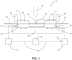
- material positioner 10 for use with a welder is shown in one embodiment of the present material positioner.
- material positioner 10 can include first fixture 12, second fixture 14, first positioning mechanism 16, second positioning mechanism 18, and/or control unit 20.
- first fixture 12 and/or second fixture 14 can conform to the geometrical characteristics of the material being welded. For instance, in some embodiments, such as shown FIGS.
- first material 22 and second material 24 corresponding to rods can be secured to first fixture 12 and second fixture 14 using upper member 28 and lower member 30.
- horizontally groove 32 can be formed in upper member 28 and/or in lower member 30 to cradle the round rods in first fixture 12 and/or second fixture 14.
- upper member 28 and lower member 30 are in an open position (not shown) for placement of the material in lower member 30.
- upper member 28 can be biased against the lower member 30 and the materials secured in first fixture 12 and/or second fixture 14.
- a pneumatic actuation can be employed to maintain placement of the material(s) in first fixture 12 and/or second fixture 14.
- other configurations can be employed, such as, but not limited to, a mechanical latch, hydraulics and springs.
- first material 22 and second material 24 having a rod-shaped configuration is discussed below.
- Other such materials can be employed, such as, but not limited to, solid wire, strand wire, flat stock, pipe and tubing.
- material positioner 10 is shown with first fixture 12 and second fixture 14 resting against a mechanical stop 38 with first fixture 12 and second fixture 14 at their corresponding first starting point 34 and second starting point 36.
- mechanical stop 38 can be employed in combination with first fixture 12 and second fixture 14.
- mechanical stop 38 can be adjustable to accommodate a range of first material 22 and/or second material 24.
- larger rods generally require larger spacing between first fixture 12 and second fixture 14 for proper welding.
- first fixture 12 and second fixture 14 can be slidably mounted to support member 40 for properly positioning first material 22 and second material 24 to corresponding first starting point 34 and second starting point 36, second position 42 (shown in FIG.
- first material 22 and second material 24 are at their corresponding first starting point 34 and second starting point 36, this configuration generally corresponds to having first material 22 and second material 24 in generally mating engagement.
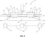
- material positioner 10 is shown with second fixture 14 positioned to place second material 24 in second position 42 for the start of the welding process.
- actuation of second fixture 14 slides along support member 40 and generally forces second material 24 against first material 22.
- second position 42 places first material 22 and second material 24 in a generally coalesced state during welding of first material 22 and second material 24.
- control of the travel of second fixture 14 is important for completing a quality weld.
- second positioning mechanism 18 is voice coil actuator (VCA) 46 employed to position second material 24 with respect to first material 22.
- control unit 20 can be adapted to send signal 48 to VCA 46.
- a permanent magnet which can be part of VCA 46 can provide a generally constant force that is used to slide second fixture 14 with second material 24 to second position 42.
- use of VCA 46 maintains a generally constant force over the life of VCA 46 whereas standard processes, such as those that use spring force for positioning, fluctuate during aging.
- VCA 46 can provide a generally constant force during travel to second position 42, during the welding process, and third position 44, as the weld is cooled, increasing the quality of the weld.
- control unit 20 can be a fixed power supply providing a predetermined voltage to VCA 46 based on the characteristics of first material 22 and/or second material 24.
- control units 20 can be employed, such as, but not limited to, a variable signal unit.
- the magnitude of the voltage can be based on the characteristics of first material 22 and/or second material 24 being welded.
- the user sends a higher or lower voltage signal 48 based on the properties of first material 22 and/or second material 24.
- solid wire, strand wire, rod, flat stock, pipe, and/or tubing require different magnitudes of force to create proper welds.
- the size of first material 22 and second material 24 can require different magnitude of force at VCA 46 for welding.
- characteristics of the type of weld desired can require different magnitudes of force at VCA 46, for example, butt joints and lap joints.
- the ability to adjust the force of VCA 46 over a wide range of operating parameters reduces the need to reconfigure welder 26 in operation.
- welder 26 is activated and heat is generated to melt the ends of first material 22 and/or second material 24.
- welder 26 can have other configurations, such as, but not limited to, resistance, spot, stud, friction, and/or energy beam.
- second positioning mechanism 18 providing a constant force, welder 26 slides second fixture 14 to second position 42 to fuse first material 22 and second material 24 together for a quality weld.
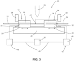
- welder 26 is deactivated and VCA 46 can continue to provide a generally constant force until welded first material 22 and second material 24 have cooled.
- the cooled pieces travel to third position 44, illustrated in FIG. 3 .
- third position 44 can vary from cycle to cycle based on the amount of time it takes to transition from a molten state to a solid state.
- welder 26 may have an increase in heat generated for a single cycle which, in turn, melts more of first material 22 and/or second material 24.
- a longer duration is then required to transition from a molten state to a solid state and, with a generally constant force applied, pushes second material 24 further into first material 22 and increases the travel to third position 44.
- upper members 28 of first fixture 12 and second fixture 14 are retracted to provide access to the welded rod for removal and setup for another cycle of welder 26.
- signal 48 to VCA 46 can be reversed. In at least some embodiments, reversing the signal overcomes the static force of second fixture 14 and places second fixture 14 at second starting point 36.
- productivity of welding first material 22 and second material 24 together, and in particular, employing a single welder 26 setup for a wide range of materials increases productivity while decreasing costs due to the use of VCA 46 for positioning first material 22 and second material 24 with a generally constant force during the welding process.
- VCA 46 can be adapted to handle a wide range of generally constant forces.
- first material 22 and second material 24 are placed at first starting point 34 and second starting points 36 with first material 22 and second material 24 in generally mating contact.
- the control unit can send signal 48 to VCA 46 which, in turns, provides a generally constant force to second fixture 14 which, in turn, provides a generally constant force between first material 22 and second material 24.
- first material 22 and second material 24 With first material 22 and second material 24 in a solid state, the second fixture remains at second starting point 36.
- Welder 26 can be energized, providing heat to first material 22 and second material 24 to melt first material 22 and/or second material 24. During melting, second material 24 and second fixture 14 travel along support member 40 until it generally reaches second position 42 to better fuse the materials together for a quality weld.
- welder 26 is deactivated and VCA 46 continues to provide the constant force until the weld is cooled.
- second material 22 and second fixture 14 can travel along support member 40 until it reaches third position 44.
- Welded first material 22 and second material 24 can be removed from first fixture 12 and second fixture 14.
- first fixture 12 and second fixture 14 can be reset to first starting point 34 and second starting point 36 based on properties and/or characteristics of the material being welded.
- the polarity of signal 48 can be reversed to VCA 46 providing an opposite magnitude of force and causing second fixture 14 to reverse travel and position second fixture 14 at second starting point 36. Reversed signal 48 can be of a general magnitude to overcome the static force of second fixture 14.
- VCA 46 increases the capability of the welder to weld a wide range of materials of different geometries and properties under a variety of joining processes without reconfiguration of the welder.
- the ability to provide a generally constant force to first material 22 and second material 24 over the life of VCA 46 and in operation over the length of travel from first starting point 34 and second starting point 36 to second position 42, and to third position 44 can improve the quality of the welds made.
- the use of VCA 46 simplifies the setup and lowers operation costs over standard and complex welders that employ spring(s), pneumatics or hydraulics.
Landscapes
- Physics & Mathematics (AREA)
- Optics & Photonics (AREA)
- Engineering & Computer Science (AREA)
- Mechanical Engineering (AREA)
- Lining Or Joining Of Plastics Or The Like (AREA)
- Arc Welding In General (AREA)
- Resistance Welding (AREA)
Claims (14)
- Materialpositionierer (10) zur Verwendung mit einem Schweißgerät, wobei der Materialpositionierer aufweist:(a) ein erstes Material und eine erste Befestigung (12), wobei das erste Material (22) an der ersten Befestigung (12) befestigt ist;(b) ein zweites Material und eine zweite Befestigung (14), wobei das zweite Material (24) an der zweiten Befestigung (14) befestigt ist;(c) einen ersten Positioniermechanismus (16), der geeignet ist, um das erste Material (22) an einem ersten Startpunkt (34) zu platzieren;(d) einen zweiten Positioniermechanismus (18), der geeignet ist, um das zweite Material (24) an einem zweiten Startpunkt (36) zu platzieren; wobei der zweite Startpunkt (36) die ersten und zweiten Materialien (22, 24) in allgemeinem Passeingriff hat, die Betätigung des zweiten Positioniermechanismus (18) im Allgemeinen das zweite Material (24) gegen das erste Material (22) zwingt und das zweite Material (24) an einer zweiten Position (42) an dem Materialpositionierer (10) verortet, und die zweite Position (42) die ersten und zweiten Materialien (22, 24) im Allgemeinen vereinigt hat;(e) eine Steuereinheit (20), die geeignet ist, ein Signal (48) an jeden der ersten und zweiten Positionierungsmechanismen (16, 18) zu senden, und das Signal (38) einstellbar ist basierend auf Charakteristika der ersten und zweiten Materialien (22, 24); und(f) einen Wärmeerzeuger (26), der zum Schweißen der ersten und zweiten Materialien (22, 24) aneinander geeignet ist, um eine Schweißnaht zu erzeugen,dadurch gekennzeichnet,
dass der zweite Positioniermechanismus (18) ein Schwingspulenaktuator (46) ist. - Materialpositionierer nach Anspruch 1, wobei, im Gebrauch, die fortgesetzte Betätigung des zweiten Positioniermechanismus (18) die ersten und zweiten Material (22, 24) an einer dritten Position (44) an dem Materialpositionierer (10) verortet, wobei die dritte Position (44) die ersten und zweiten Materialien (22, 24) im Allgemeinen kühlt.
- Materialpositionierer nach Anspruch 2, wobei, in der dritten Position (44) an dem Materialpositionierer (10), die ersten und zweiten Materialien (22, 24) von einem geschmolzenen Zustand in einen festen Zustand übergehen.
- Materialpositionierer nach Anspruch 1, wobei das Signal (48) eine Spannung ist.
- Materialpositionierer nach Anspruch 4, wobei die Spannung eine Größe hat, die auf den Eigenschaften der ersten und zweiten Materialien (22, 24) basiert.
- Materialpositionierer nach Anspruch 1, wobei das Signal (48) durch eine einstellbare Stromversorgung bereitgestellt wird.
- Materialpositionierer nach Anspruch 1, wobei das Signal (48) durch eine fixe Stromversorgung bereitgestellt wird.
- Materialpositionierer nach Anspruch 1, wobei die Betätigung des zweiten Positionierungsmechanismus (18) dazu geeignet ist, während des Wärmeerzeugerschweißens eine allgemein konstante Kraft zwischen den ersten und zweiten Materialen (22, 24) zu erzeugen.
- Materialpositionierer nach Anspruch 1, wobei das Schweißen ein Widerstandsschweißen, Punktschweißen, Bolzenschweißen, Reibschweißen oder Energiestrahlen ist.
- Materialpositionierer nach Anspruch 1, wobei die erste und die zweite Befestigung (12, 14) so angeordnet sind, dass die Schweißnaht als Stumpfverbindung oder eine Überlappverbindung erreichbar ist.
- Materialpositionierer nach Anspruch 1, wobei die ersten und zweiten Materialien (22, 24) Volldraht, Litzendraht, stabförmig, Flachmaterial, Rohre oder Schläuche sind.
- Schweißverfahren zum Verschweißen eines ersten und eines zweiten Materials (22, 24) mit einem Schweißgerät (26) und einem Materialpositionierer (10), wobei der Materialpositionierer (10) einen ersten Positioniermechanismus (16), einen zweiten Positioniermechanismus (18), ein erstes Material (22) mit einem ersten Startpunkt (34) an dem Materialpositionierer (10), ein zweites Material (24) mit einem zweiten Startpunkt (36) an dem Materialpositionierer (10) und einer zweiten Position (42) an dem Materialpositionierer (10), und eine Steuereinheit (20), die geeignet ist, um ein erstes Signal an die ersten und zweiten Positioniermechanismen (16, 18) zu senden, aufweist, wobei das Verfahren aufweist:(a) Platzieren des ersten Materials (22) an dem ersten Startpunkt (34);(b) Platzieren des zweiten Materials (24) an dem ersten Startpunkt (36);(c) Senden des ersten Signals von der Steuereinheit (20) an den zweiten Positioniermechanismus (18);(d) Verschweißen der ersten und zweiten Materialien(22, 24) miteinander; und(e) Verorten der ersten und zweiten Materialien (22, 24) in im Allgemeinen vereinigter Verbindung;dadurch gekennzeichnet,
dass der zweite Positioniermechanismus (18) ein Schwingspulenaktuator (46) ist. - Verfahren nach Anspruch 12, weiterhin aufweisend:
(f) Senden eines zweiten Signals an den zweiten Positioniermechanismus (18), um den zweiten Positioniermechanismus (18) an den zweiten Startpunkt (36) zurückzubringen. - Verfahren nach Anspruch 13, wobei das zweite Signal gegenüber dem ersten Signal eine umgekehrte Polarität aufweist.
Applications Claiming Priority (2)
| Application Number | Priority Date | Filing Date | Title |
|---|---|---|---|
| US201862627691P | 2018-02-07 | 2018-02-07 | |
| PCT/US2019/017084 WO2019157201A1 (en) | 2018-02-07 | 2019-02-07 | Material positioner for welding apparatus and method |
Publications (3)
| Publication Number | Publication Date |
|---|---|
| EP3749481A1 EP3749481A1 (de) | 2020-12-16 |
| EP3749481B1 true EP3749481B1 (de) | 2023-11-22 |
| EP3749481C0 EP3749481C0 (de) | 2023-11-22 |
Family
ID=65718079
Family Applications (1)
| Application Number | Title | Priority Date | Filing Date |
|---|---|---|---|
| EP19709816.3A Active EP3749481B1 (de) | 2018-02-07 | 2019-02-07 | Materialpositionierer für schweissvorrichtung und verfahren |
Country Status (3)
| Country | Link |
|---|---|
| US (2) | US20200384583A1 (de) |
| EP (1) | EP3749481B1 (de) |
| WO (1) | WO2019157201A1 (de) |
Family Cites Families (35)
| Publication number | Priority date | Publication date | Assignee | Title |
|---|---|---|---|---|
| US3245201A (en) * | 1962-10-22 | 1966-04-12 | Karl M Richardson | Aligning device |
| US3600580A (en) * | 1969-09-22 | 1971-08-17 | Atomic Energy Commission | Charged particle beam density measurement device |
| US3938797A (en) * | 1974-01-09 | 1976-02-17 | The Pandjiris Weldment Co. | Clamping device for welding seamer |
| JPH05235077A (ja) * | 1991-04-26 | 1993-09-10 | Texas Instr Inc <Ti> | 半導体デバイスボンディング用の極座標運動ボンディングヘッド |
| US5853655A (en) * | 1996-11-07 | 1998-12-29 | Baker; Ronald Glenn | Magnetic wheel guided carriage with positioning arm |
| US6249506B1 (en) * | 1998-01-27 | 2001-06-19 | Matsushita Electric Industrial Co., Ltd. | Medium attaching device and disk drive apparatus |
| JP4268360B2 (ja) * | 1999-10-04 | 2009-05-27 | パナソニック株式会社 | 摩擦接合方法と装置 |
| AU2001227690A1 (en) * | 2000-01-11 | 2001-07-24 | Electro Scientific Industries, Inc. | Abbe error correction system and method |
| JP2002151545A (ja) * | 2000-11-10 | 2002-05-24 | Nec Corp | ワイヤボンディング装置 |
| JP3885867B2 (ja) * | 2000-11-29 | 2007-02-28 | 日本電気株式会社 | ワイヤボンディング装置 |
| JP2003163234A (ja) * | 2001-11-27 | 2003-06-06 | Nec Electronics Corp | ワイヤボンディング装置およびワイヤボンディング方法 |
| US6783052B2 (en) * | 2002-11-21 | 2004-08-31 | Asm Technology Singapore Pte Ltd | Clamp actuation mechanism |
| US6899262B2 (en) * | 2003-05-19 | 2005-05-31 | Asm Technology Singapore Pte Ltd | Clamping device |
| US7774917B2 (en) * | 2003-07-17 | 2010-08-17 | Tubefuse Applications B.V. | Forge welding tubulars |
| US7129442B2 (en) * | 2004-03-09 | 2006-10-31 | Specialty Tooling Systems, Inc. | Welding machine |
| FR2869558B1 (fr) * | 2004-04-29 | 2006-09-01 | Vai Clecim Soc Par Actions Sim | Procede de reglage de l'epaisseur du cordon de soudure de deux toles metalliques |
| US7025243B2 (en) * | 2004-06-16 | 2006-04-11 | Asm Technology Singapore Pte. Ltd. | Bondhead for wire bonding apparatus |
| WO2008039986A2 (en) * | 2006-09-28 | 2008-04-03 | Keystone Semiconductor, Inc. | Spread spectrum clock generator using arrival locked loop technology |
| US7532428B2 (en) * | 2007-01-19 | 2009-05-12 | Asm Technology Singapore Pte Ltd. | Soft touch clamp actuation mechanism |
| US7760331B2 (en) * | 2007-02-20 | 2010-07-20 | Electro Scientific Industries, Inc. | Decoupled, multiple stage positioning system |
| JP4505491B2 (ja) * | 2007-11-05 | 2010-07-21 | 新日本製鐵株式会社 | 鋼管材の溶接部加熱装置及び方法 |
| DE102008029477A1 (de) * | 2008-06-20 | 2009-12-24 | Vacuumschmelze Gmbh & Co. Kg | Stromsensoranordnung zur Messung von Strömen in einem Primärleiter |
| JP5139922B2 (ja) * | 2008-08-25 | 2013-02-06 | 株式会社ディスコ | レーザー加工装置 |
| JP4808283B1 (ja) * | 2010-06-30 | 2011-11-02 | 株式会社新川 | 電子部品実装装置及び電子部品実装方法 |
| JP5149355B2 (ja) * | 2010-09-08 | 2013-02-20 | 富士重工業株式会社 | スポット溶接方法及びスポット溶接装置 |
| WO2013085962A1 (en) * | 2011-12-05 | 2013-06-13 | Apci, Llc | Apparatus for linear friction welding |
| CN104174983A (zh) * | 2014-05-09 | 2014-12-03 | 广州市爱司凯科技股份有限公司 | 音圈马达镜头的定位方法 |
| JP6840540B2 (ja) * | 2014-11-14 | 2021-03-10 | 株式会社ニコン | 造形装置 |
| CN205105260U (zh) * | 2015-09-30 | 2016-03-23 | 武汉钢铁(集团)公司 | 一种调度终端 |
| US10675698B2 (en) * | 2015-12-31 | 2020-06-09 | Illinois Tool Works Inc. | Wire delivery apparatus with a non-rotational actuator |
| US10730128B2 (en) * | 2016-01-20 | 2020-08-04 | Western Digital Technologies, Inc. | Reliable transportation mechanism for micro solder balls |
| US10500676B2 (en) * | 2016-02-19 | 2019-12-10 | Faro Technologies, Inc. | Voice coil motor operated linear actuator |
| CN106346151A (zh) * | 2016-11-02 | 2017-01-25 | 辽宁中蓝电子科技有限公司 | 一种vcm马达激光焊拼治具 |
| CN107160050B (zh) * | 2017-07-04 | 2023-03-24 | 东莞市凯格精机股份有限公司 | 一种焊线机 |
| US20190351501A1 (en) * | 2018-05-21 | 2019-11-21 | Illinois Tool Works Inc. | Welding power supplies and user interfaces for welding power supplies |
-
2019
- 2019-02-07 WO PCT/US2019/017084 patent/WO2019157201A1/en not_active Ceased
- 2019-02-07 EP EP19709816.3A patent/EP3749481B1/de active Active
-
2020
- 2020-08-07 US US16/987,401 patent/US20200384583A1/en not_active Abandoned
-
2023
- 2023-12-29 US US18/399,999 patent/US20240131636A1/en active Pending
Also Published As
| Publication number | Publication date |
|---|---|
| EP3749481C0 (de) | 2023-11-22 |
| US20200384583A1 (en) | 2020-12-10 |
| US20240131636A1 (en) | 2024-04-25 |
| WO2019157201A1 (en) | 2019-08-15 |
| EP3749481A1 (de) | 2020-12-16 |
Similar Documents
| Publication | Publication Date | Title |
|---|---|---|
| US8993918B2 (en) | Spot-welding method and spot-welding device | |
| AU595334B2 (en) | Induction heating pressure welding with rotary bus bar joint | |
| JP6696509B2 (ja) | 可動加圧部材を有するスポット溶接電極、及びそれを用いたスポット溶接方法 | |
| US4286744A (en) | Process for joining narrow width thin gage metal or alloy strip | |
| JPWO2015033537A1 (ja) | インダイレクトスポット溶接装置 | |
| JPWO2015037652A1 (ja) | 抵抗スポット溶接方法および溶接構造物 | |
| EP3749481B1 (de) | Materialpositionierer für schweissvorrichtung und verfahren | |
| JP5930839B2 (ja) | 抵抗溶接装置及び抵抗溶接方法 | |
| US6566624B2 (en) | Welding assembly with nestable conductive ends | |
| US3198413A (en) | Apparatus for joining metal strip | |
| WO1998039130A1 (en) | Method for arc welding with melting electrode | |
| US20200398360A1 (en) | System and method for forming a weld along a length | |
| US4129771A (en) | Method for butt-welding cylindrical metallic rods | |
| CN218363288U (zh) | 多层结构钢帘线股绳的焊接结构 | |
| KR101833477B1 (ko) | 마찰 교반 용접에 의한 핀홀 리페어 방법 및 시스템 | |
| Thomas et al. | Cold welding | |
| US6903299B2 (en) | Resistance welding tip assembly | |
| US4999476A (en) | Machine for pressure welding workpieces heated with arc moving in magnetic field | |
| JP3712918B2 (ja) | スポット溶接方法およびスポット溶接装置 | |
| JPS6044186A (ja) | リング切断面面合せ装置 | |
| JP6090910B2 (ja) | スポット溶接方法 | |
| JP2012250253A (ja) | スポット溶接機およびスポット溶接方法 | |
| JP4305789B2 (ja) | 抵抗シーム溶接装置 | |
| CA1152387A (en) | Process for joining narrow width thin gage metal or alloy strip | |
| NL2022864B1 (en) | Method for resistance welding and resistance welding apparatus |
Legal Events
| Date | Code | Title | Description |
|---|---|---|---|
| STAA | Information on the status of an ep patent application or granted ep patent |
Free format text: STATUS: UNKNOWN |
|
| STAA | Information on the status of an ep patent application or granted ep patent |
Free format text: STATUS: THE INTERNATIONAL PUBLICATION HAS BEEN MADE |
|
| PUAI | Public reference made under article 153(3) epc to a published international application that has entered the european phase |
Free format text: ORIGINAL CODE: 0009012 |
|
| STAA | Information on the status of an ep patent application or granted ep patent |
Free format text: STATUS: REQUEST FOR EXAMINATION WAS MADE |
|
| 17P | Request for examination filed |
Effective date: 20200827 |
|
| AK | Designated contracting states |
Kind code of ref document: A1 Designated state(s): AL AT BE BG CH CY CZ DE DK EE ES FI FR GB GR HR HU IE IS IT LI LT LU LV MC MK MT NL NO PL PT RO RS SE SI SK SM TR |
|
| AX | Request for extension of the european patent |
Extension state: BA ME |
|
| DAV | Request for validation of the european patent (deleted) | ||
| DAX | Request for extension of the european patent (deleted) | ||
| GRAP | Despatch of communication of intention to grant a patent |
Free format text: ORIGINAL CODE: EPIDOSNIGR1 |
|
| STAA | Information on the status of an ep patent application or granted ep patent |
Free format text: STATUS: GRANT OF PATENT IS INTENDED |
|
| INTG | Intention to grant announced |
Effective date: 20230607 |
|
| GRAS | Grant fee paid |
Free format text: ORIGINAL CODE: EPIDOSNIGR3 |
|
| GRAA | (expected) grant |
Free format text: ORIGINAL CODE: 0009210 |
|
| STAA | Information on the status of an ep patent application or granted ep patent |
Free format text: STATUS: THE PATENT HAS BEEN GRANTED |
|
| AK | Designated contracting states |
Kind code of ref document: B1 Designated state(s): AL AT BE BG CH CY CZ DE DK EE ES FI FR GB GR HR HU IE IS IT LI LT LU LV MC MK MT NL NO PL PT RO RS SE SI SK SM TR |
|
| REG | Reference to a national code |
Ref country code: GB Ref legal event code: FG4D |
|
| REG | Reference to a national code |
Ref country code: CH Ref legal event code: EP |
|
| REG | Reference to a national code |
Ref country code: DE Ref legal event code: R096 Ref document number: 602019041835 Country of ref document: DE |
|
| REG | Reference to a national code |
Ref country code: IE Ref legal event code: FG4D |
|
| U01 | Request for unitary effect filed |
Effective date: 20231123 |
|
| U07 | Unitary effect registered |
Designated state(s): AT BE BG DE DK EE FI FR IT LT LU LV MT NL PT SE SI Effective date: 20231130 |
|
| U20 | Renewal fee for the european patent with unitary effect paid |
Year of fee payment: 6 Effective date: 20240227 |
|
| PG25 | Lapsed in a contracting state [announced via postgrant information from national office to epo] |
Ref country code: GR Free format text: LAPSE BECAUSE OF FAILURE TO SUBMIT A TRANSLATION OF THE DESCRIPTION OR TO PAY THE FEE WITHIN THE PRESCRIBED TIME-LIMIT Effective date: 20240223 |
|
| PG25 | Lapsed in a contracting state [announced via postgrant information from national office to epo] |
Ref country code: IS Free format text: LAPSE BECAUSE OF FAILURE TO SUBMIT A TRANSLATION OF THE DESCRIPTION OR TO PAY THE FEE WITHIN THE PRESCRIBED TIME-LIMIT Effective date: 20240322 |
|
| PG25 | Lapsed in a contracting state [announced via postgrant information from national office to epo] |
Ref country code: ES Free format text: LAPSE BECAUSE OF FAILURE TO SUBMIT A TRANSLATION OF THE DESCRIPTION OR TO PAY THE FEE WITHIN THE PRESCRIBED TIME-LIMIT Effective date: 20231122 |
|
| PG25 | Lapsed in a contracting state [announced via postgrant information from national office to epo] |
Ref country code: IS Free format text: LAPSE BECAUSE OF FAILURE TO SUBMIT A TRANSLATION OF THE DESCRIPTION OR TO PAY THE FEE WITHIN THE PRESCRIBED TIME-LIMIT Effective date: 20240322 Ref country code: GR Free format text: LAPSE BECAUSE OF FAILURE TO SUBMIT A TRANSLATION OF THE DESCRIPTION OR TO PAY THE FEE WITHIN THE PRESCRIBED TIME-LIMIT Effective date: 20240223 Ref country code: ES Free format text: LAPSE BECAUSE OF FAILURE TO SUBMIT A TRANSLATION OF THE DESCRIPTION OR TO PAY THE FEE WITHIN THE PRESCRIBED TIME-LIMIT Effective date: 20231122 |
|
| PG25 | Lapsed in a contracting state [announced via postgrant information from national office to epo] |
Ref country code: RS Free format text: LAPSE BECAUSE OF FAILURE TO SUBMIT A TRANSLATION OF THE DESCRIPTION OR TO PAY THE FEE WITHIN THE PRESCRIBED TIME-LIMIT Effective date: 20231122 Ref country code: PL Free format text: LAPSE BECAUSE OF FAILURE TO SUBMIT A TRANSLATION OF THE DESCRIPTION OR TO PAY THE FEE WITHIN THE PRESCRIBED TIME-LIMIT Effective date: 20231122 Ref country code: NO Free format text: LAPSE BECAUSE OF FAILURE TO SUBMIT A TRANSLATION OF THE DESCRIPTION OR TO PAY THE FEE WITHIN THE PRESCRIBED TIME-LIMIT Effective date: 20240222 Ref country code: HR Free format text: LAPSE BECAUSE OF FAILURE TO SUBMIT A TRANSLATION OF THE DESCRIPTION OR TO PAY THE FEE WITHIN THE PRESCRIBED TIME-LIMIT Effective date: 20231122 |
|
| PG25 | Lapsed in a contracting state [announced via postgrant information from national office to epo] |
Ref country code: CZ Free format text: LAPSE BECAUSE OF FAILURE TO SUBMIT A TRANSLATION OF THE DESCRIPTION OR TO PAY THE FEE WITHIN THE PRESCRIBED TIME-LIMIT Effective date: 20231122 |
|
| PG25 | Lapsed in a contracting state [announced via postgrant information from national office to epo] |
Ref country code: SK Free format text: LAPSE BECAUSE OF FAILURE TO SUBMIT A TRANSLATION OF THE DESCRIPTION OR TO PAY THE FEE WITHIN THE PRESCRIBED TIME-LIMIT Effective date: 20231122 |
|
| PG25 | Lapsed in a contracting state [announced via postgrant information from national office to epo] |
Ref country code: SM Free format text: LAPSE BECAUSE OF FAILURE TO SUBMIT A TRANSLATION OF THE DESCRIPTION OR TO PAY THE FEE WITHIN THE PRESCRIBED TIME-LIMIT Effective date: 20231122 Ref country code: SK Free format text: LAPSE BECAUSE OF FAILURE TO SUBMIT A TRANSLATION OF THE DESCRIPTION OR TO PAY THE FEE WITHIN THE PRESCRIBED TIME-LIMIT Effective date: 20231122 Ref country code: RO Free format text: LAPSE BECAUSE OF FAILURE TO SUBMIT A TRANSLATION OF THE DESCRIPTION OR TO PAY THE FEE WITHIN THE PRESCRIBED TIME-LIMIT Effective date: 20231122 Ref country code: CZ Free format text: LAPSE BECAUSE OF FAILURE TO SUBMIT A TRANSLATION OF THE DESCRIPTION OR TO PAY THE FEE WITHIN THE PRESCRIBED TIME-LIMIT Effective date: 20231122 |
|
| REG | Reference to a national code |
Ref country code: DE Ref legal event code: R097 Ref document number: 602019041835 Country of ref document: DE |
|
| PLBE | No opposition filed within time limit |
Free format text: ORIGINAL CODE: 0009261 |
|
| STAA | Information on the status of an ep patent application or granted ep patent |
Free format text: STATUS: NO OPPOSITION FILED WITHIN TIME LIMIT |
|
| PG25 | Lapsed in a contracting state [announced via postgrant information from national office to epo] |
Ref country code: MC Free format text: LAPSE BECAUSE OF FAILURE TO SUBMIT A TRANSLATION OF THE DESCRIPTION OR TO PAY THE FEE WITHIN THE PRESCRIBED TIME-LIMIT Effective date: 20231122 |
|
| REG | Reference to a national code |
Ref country code: CH Ref legal event code: PL |
|
| PG25 | Lapsed in a contracting state [announced via postgrant information from national office to epo] |
Ref country code: CH Free format text: LAPSE BECAUSE OF NON-PAYMENT OF DUE FEES Effective date: 20240229 |
|
| 26N | No opposition filed |
Effective date: 20240823 |
|
| PG25 | Lapsed in a contracting state [announced via postgrant information from national office to epo] |
Ref country code: CH Free format text: LAPSE BECAUSE OF NON-PAYMENT OF DUE FEES Effective date: 20240229 |
|
| PG25 | Lapsed in a contracting state [announced via postgrant information from national office to epo] |
Ref country code: IE Free format text: LAPSE BECAUSE OF NON-PAYMENT OF DUE FEES Effective date: 20240207 |
|
| PG25 | Lapsed in a contracting state [announced via postgrant information from national office to epo] |
Ref country code: IE Free format text: LAPSE BECAUSE OF NON-PAYMENT OF DUE FEES Effective date: 20240207 |
|
| U20 | Renewal fee for the european patent with unitary effect paid |
Year of fee payment: 7 Effective date: 20250227 |
|
| PGFP | Annual fee paid to national office [announced via postgrant information from national office to epo] |
Ref country code: GB Payment date: 20250227 Year of fee payment: 7 |
|
| PG25 | Lapsed in a contracting state [announced via postgrant information from national office to epo] |
Ref country code: CY Free format text: LAPSE BECAUSE OF FAILURE TO SUBMIT A TRANSLATION OF THE DESCRIPTION OR TO PAY THE FEE WITHIN THE PRESCRIBED TIME-LIMIT; INVALID AB INITIO Effective date: 20190207 |
|
| PG25 | Lapsed in a contracting state [announced via postgrant information from national office to epo] |
Ref country code: HU Free format text: LAPSE BECAUSE OF FAILURE TO SUBMIT A TRANSLATION OF THE DESCRIPTION OR TO PAY THE FEE WITHIN THE PRESCRIBED TIME-LIMIT; INVALID AB INITIO Effective date: 20190207 |
|
| PG25 | Lapsed in a contracting state [announced via postgrant information from national office to epo] |
Ref country code: TR Free format text: LAPSE BECAUSE OF FAILURE TO SUBMIT A TRANSLATION OF THE DESCRIPTION OR TO PAY THE FEE WITHIN THE PRESCRIBED TIME-LIMIT Effective date: 20231122 |