EP3748712A1 - Batterieleistungsgewinnungs- und integrationsstruktur, batteriepack und fahrzeug - Google Patents
Batterieleistungsgewinnungs- und integrationsstruktur, batteriepack und fahrzeug Download PDFInfo
- Publication number
- EP3748712A1 EP3748712A1 EP19750601.7A EP19750601A EP3748712A1 EP 3748712 A1 EP3748712 A1 EP 3748712A1 EP 19750601 A EP19750601 A EP 19750601A EP 3748712 A1 EP3748712 A1 EP 3748712A1
- Authority
- EP
- European Patent Office
- Prior art keywords
- copper bar
- battery
- end plate
- battery pack
- integrated structure
- Prior art date
- Legal status (The legal status is an assumption and is not a legal conclusion. Google has not performed a legal analysis and makes no representation as to the accuracy of the status listed.)
- Withdrawn
Links
- 238000000605 extraction Methods 0.000 title 1
- 230000010354 integration Effects 0.000 title 1
- RYGMFSIKBFXOCR-UHFFFAOYSA-N Copper Chemical compound [Cu] RYGMFSIKBFXOCR-UHFFFAOYSA-N 0.000 claims abstract description 111
- 229910052802 copper Inorganic materials 0.000 claims abstract description 111
- 239000010949 copper Substances 0.000 claims abstract description 111
- 238000001746 injection moulding Methods 0.000 claims abstract description 15
- 239000011810 insulating material Substances 0.000 claims abstract description 4
- 230000002159 abnormal effect Effects 0.000 description 1
- 239000006227 byproduct Substances 0.000 description 1
- 239000000306 component Substances 0.000 description 1
- 239000008358 core component Substances 0.000 description 1
- 238000010586 diagram Methods 0.000 description 1
- 238000010891 electric arc Methods 0.000 description 1
- 238000004146 energy storage Methods 0.000 description 1
- 238000009413 insulation Methods 0.000 description 1
- 230000007774 longterm Effects 0.000 description 1
- 238000012423 maintenance Methods 0.000 description 1
- 238000004519 manufacturing process Methods 0.000 description 1
- 239000000243 solution Substances 0.000 description 1
Images


Classifications
-
- H—ELECTRICITY
- H01—ELECTRIC ELEMENTS
- H01M—PROCESSES OR MEANS, e.g. BATTERIES, FOR THE DIRECT CONVERSION OF CHEMICAL ENERGY INTO ELECTRICAL ENERGY
- H01M50/00—Constructional details or processes of manufacture of the non-active parts of electrochemical cells other than fuel cells, e.g. hybrid cells
- H01M50/20—Mountings; Secondary casings or frames; Racks, modules or packs; Suspension devices; Shock absorbers; Transport or carrying devices; Holders
- H01M50/271—Lids or covers for the racks or secondary casings
- H01M50/273—Lids or covers for the racks or secondary casings characterised by the material
- H01M50/278—Organic material
-
- B—PERFORMING OPERATIONS; TRANSPORTING
- B60—VEHICLES IN GENERAL
- B60K—ARRANGEMENT OR MOUNTING OF PROPULSION UNITS OR OF TRANSMISSIONS IN VEHICLES; ARRANGEMENT OR MOUNTING OF PLURAL DIVERSE PRIME-MOVERS IN VEHICLES; AUXILIARY DRIVES FOR VEHICLES; INSTRUMENTATION OR DASHBOARDS FOR VEHICLES; ARRANGEMENTS IN CONNECTION WITH COOLING, AIR INTAKE, GAS EXHAUST OR FUEL SUPPLY OF PROPULSION UNITS IN VEHICLES
- B60K1/00—Arrangement or mounting of electrical propulsion units
- B60K1/04—Arrangement or mounting of electrical propulsion units of the electric storage means for propulsion
-
- H—ELECTRICITY
- H01—ELECTRIC ELEMENTS
- H01M—PROCESSES OR MEANS, e.g. BATTERIES, FOR THE DIRECT CONVERSION OF CHEMICAL ENERGY INTO ELECTRICAL ENERGY
- H01M50/00—Constructional details or processes of manufacture of the non-active parts of electrochemical cells other than fuel cells, e.g. hybrid cells
- H01M50/20—Mountings; Secondary casings or frames; Racks, modules or packs; Suspension devices; Shock absorbers; Transport or carrying devices; Holders
-
- H—ELECTRICITY
- H01—ELECTRIC ELEMENTS
- H01M—PROCESSES OR MEANS, e.g. BATTERIES, FOR THE DIRECT CONVERSION OF CHEMICAL ENERGY INTO ELECTRICAL ENERGY
- H01M50/00—Constructional details or processes of manufacture of the non-active parts of electrochemical cells other than fuel cells, e.g. hybrid cells
- H01M50/10—Primary casings; Jackets or wrappings
- H01M50/147—Lids or covers
- H01M50/148—Lids or covers characterised by their shape
- H01M50/15—Lids or covers characterised by their shape for prismatic or rectangular cells
-
- H—ELECTRICITY
- H01—ELECTRIC ELEMENTS
- H01M—PROCESSES OR MEANS, e.g. BATTERIES, FOR THE DIRECT CONVERSION OF CHEMICAL ENERGY INTO ELECTRICAL ENERGY
- H01M50/00—Constructional details or processes of manufacture of the non-active parts of electrochemical cells other than fuel cells, e.g. hybrid cells
- H01M50/10—Primary casings; Jackets or wrappings
- H01M50/172—Arrangements of electric connectors penetrating the casing
- H01M50/174—Arrangements of electric connectors penetrating the casing adapted for the shape of the cells
- H01M50/176—Arrangements of electric connectors penetrating the casing adapted for the shape of the cells for prismatic or rectangular cells
-
- H—ELECTRICITY
- H01—ELECTRIC ELEMENTS
- H01M—PROCESSES OR MEANS, e.g. BATTERIES, FOR THE DIRECT CONVERSION OF CHEMICAL ENERGY INTO ELECTRICAL ENERGY
- H01M50/00—Constructional details or processes of manufacture of the non-active parts of electrochemical cells other than fuel cells, e.g. hybrid cells
- H01M50/20—Mountings; Secondary casings or frames; Racks, modules or packs; Suspension devices; Shock absorbers; Transport or carrying devices; Holders
- H01M50/204—Racks, modules or packs for multiple batteries or multiple cells
- H01M50/207—Racks, modules or packs for multiple batteries or multiple cells characterised by their shape
- H01M50/209—Racks, modules or packs for multiple batteries or multiple cells characterised by their shape adapted for prismatic or rectangular cells
-
- H—ELECTRICITY
- H01—ELECTRIC ELEMENTS
- H01M—PROCESSES OR MEANS, e.g. BATTERIES, FOR THE DIRECT CONVERSION OF CHEMICAL ENERGY INTO ELECTRICAL ENERGY
- H01M50/00—Constructional details or processes of manufacture of the non-active parts of electrochemical cells other than fuel cells, e.g. hybrid cells
- H01M50/20—Mountings; Secondary casings or frames; Racks, modules or packs; Suspension devices; Shock absorbers; Transport or carrying devices; Holders
- H01M50/233—Mountings; Secondary casings or frames; Racks, modules or packs; Suspension devices; Shock absorbers; Transport or carrying devices; Holders characterised by physical properties of casings or racks, e.g. dimensions
- H01M50/24—Mountings; Secondary casings or frames; Racks, modules or packs; Suspension devices; Shock absorbers; Transport or carrying devices; Holders characterised by physical properties of casings or racks, e.g. dimensions adapted for protecting batteries from their environment, e.g. from corrosion
-
- H—ELECTRICITY
- H01—ELECTRIC ELEMENTS
- H01M—PROCESSES OR MEANS, e.g. BATTERIES, FOR THE DIRECT CONVERSION OF CHEMICAL ENERGY INTO ELECTRICAL ENERGY
- H01M50/00—Constructional details or processes of manufacture of the non-active parts of electrochemical cells other than fuel cells, e.g. hybrid cells
- H01M50/20—Mountings; Secondary casings or frames; Racks, modules or packs; Suspension devices; Shock absorbers; Transport or carrying devices; Holders
- H01M50/284—Mountings; Secondary casings or frames; Racks, modules or packs; Suspension devices; Shock absorbers; Transport or carrying devices; Holders with incorporated circuit boards, e.g. printed circuit boards [PCB]
-
- H—ELECTRICITY
- H01—ELECTRIC ELEMENTS
- H01M—PROCESSES OR MEANS, e.g. BATTERIES, FOR THE DIRECT CONVERSION OF CHEMICAL ENERGY INTO ELECTRICAL ENERGY
- H01M50/00—Constructional details or processes of manufacture of the non-active parts of electrochemical cells other than fuel cells, e.g. hybrid cells
- H01M50/20—Mountings; Secondary casings or frames; Racks, modules or packs; Suspension devices; Shock absorbers; Transport or carrying devices; Holders
- H01M50/296—Mountings; Secondary casings or frames; Racks, modules or packs; Suspension devices; Shock absorbers; Transport or carrying devices; Holders characterised by terminals of battery packs
-
- H—ELECTRICITY
- H01—ELECTRIC ELEMENTS
- H01M—PROCESSES OR MEANS, e.g. BATTERIES, FOR THE DIRECT CONVERSION OF CHEMICAL ENERGY INTO ELECTRICAL ENERGY
- H01M50/00—Constructional details or processes of manufacture of the non-active parts of electrochemical cells other than fuel cells, e.g. hybrid cells
- H01M50/50—Current conducting connections for cells or batteries
- H01M50/502—Interconnectors for connecting terminals of adjacent batteries; Interconnectors for connecting cells outside a battery casing
- H01M50/503—Interconnectors for connecting terminals of adjacent batteries; Interconnectors for connecting cells outside a battery casing characterised by the shape of the interconnectors
-
- H—ELECTRICITY
- H01—ELECTRIC ELEMENTS
- H01M—PROCESSES OR MEANS, e.g. BATTERIES, FOR THE DIRECT CONVERSION OF CHEMICAL ENERGY INTO ELECTRICAL ENERGY
- H01M50/00—Constructional details or processes of manufacture of the non-active parts of electrochemical cells other than fuel cells, e.g. hybrid cells
- H01M50/50—Current conducting connections for cells or batteries
- H01M50/543—Terminals
- H01M50/545—Terminals formed by the casing of the cells
-
- H—ELECTRICITY
- H01—ELECTRIC ELEMENTS
- H01R—ELECTRICALLY-CONDUCTIVE CONNECTIONS; STRUCTURAL ASSOCIATIONS OF A PLURALITY OF MUTUALLY-INSULATED ELECTRICAL CONNECTING ELEMENTS; COUPLING DEVICES; CURRENT COLLECTORS
- H01R12/00—Structural associations of a plurality of mutually-insulated electrical connecting elements, specially adapted for printed circuits, e.g. printed circuit boards [PCB], flat or ribbon cables, or like generally planar structures, e.g. terminal strips, terminal blocks; Coupling devices specially adapted for printed circuits, flat or ribbon cables, or like generally planar structures; Terminals specially adapted for contact with, or insertion into, printed circuits, flat or ribbon cables, or like generally planar structures
- H01R12/70—Coupling devices
- H01R12/77—Coupling devices for flexible printed circuits, flat or ribbon cables or like structures
- H01R12/771—Details
-
- H—ELECTRICITY
- H01—ELECTRIC ELEMENTS
- H01M—PROCESSES OR MEANS, e.g. BATTERIES, FOR THE DIRECT CONVERSION OF CHEMICAL ENERGY INTO ELECTRICAL ENERGY
- H01M2220/00—Batteries for particular applications
- H01M2220/20—Batteries in motive systems, e.g. vehicle, ship, plane
-
- H—ELECTRICITY
- H01—ELECTRIC ELEMENTS
- H01M—PROCESSES OR MEANS, e.g. BATTERIES, FOR THE DIRECT CONVERSION OF CHEMICAL ENERGY INTO ELECTRICAL ENERGY
- H01M50/00—Constructional details or processes of manufacture of the non-active parts of electrochemical cells other than fuel cells, e.g. hybrid cells
- H01M50/50—Current conducting connections for cells or batteries
-
- H—ELECTRICITY
- H01—ELECTRIC ELEMENTS
- H01R—ELECTRICALLY-CONDUCTIVE CONNECTIONS; STRUCTURAL ASSOCIATIONS OF A PLURALITY OF MUTUALLY-INSULATED ELECTRICAL CONNECTING ELEMENTS; COUPLING DEVICES; CURRENT COLLECTORS
- H01R2201/00—Connectors or connections adapted for particular applications
- H01R2201/26—Connectors or connections adapted for particular applications for vehicles
-
- Y—GENERAL TAGGING OF NEW TECHNOLOGICAL DEVELOPMENTS; GENERAL TAGGING OF CROSS-SECTIONAL TECHNOLOGIES SPANNING OVER SEVERAL SECTIONS OF THE IPC; TECHNICAL SUBJECTS COVERED BY FORMER USPC CROSS-REFERENCE ART COLLECTIONS [XRACs] AND DIGESTS
- Y02—TECHNOLOGIES OR APPLICATIONS FOR MITIGATION OR ADAPTATION AGAINST CLIMATE CHANGE
- Y02E—REDUCTION OF GREENHOUSE GAS [GHG] EMISSIONS, RELATED TO ENERGY GENERATION, TRANSMISSION OR DISTRIBUTION
- Y02E60/00—Enabling technologies; Technologies with a potential or indirect contribution to GHG emissions mitigation
- Y02E60/10—Energy storage using batteries
Definitions
- the present disclosure relates to the field of electric vehicles, and in particular, to a battery power lead-out integrated structure, a battery pack, and a vehicle.
- a battery pack is a core component of a hybrid electric vehicle and an electric vehicle.
- the battery pack is mainly composed of a battery pack housing, a battery group , and a copper bar.
- the battery pack housing is wrapped outside the battery group, the battery group is formed by connecting a plurality of cells in series and parallel, and the copper bar leads out power of the battery group to the outside of the battery pack housing.
- the copper bar passes through an opening on the battery pack housing to lead out total positive and negative electrodes of the battery to the outside of the battery pack housing.
- the copper bar is covered with an insulating film.
- the present disclosure proposes a battery power lead-out integrated structure, which can prevent electric leakage as a result of friction with the battery pack housing due to a copper bar passing through an opening on a battery pack housing, thereby improving safety.
- the present disclosure further provides a battery pack having the foregoing battery power lead-out integrated structure.
- the present disclosure further provides a vehicle having the foregoing battery pack.
- a battery power lead-out integrated structure includes an end plate as a part of a battery pack housing and a copper bar for leading out two electrodes of a battery to outside of the battery pack housing, where the end plate is made of an insulating material, and the copper bar is encapsulated in the end plate by injection molding, electrical connection portions of the copper bar being exposed.
- the battery power lead-out integrated structure of the present disclosure only a part to be electrically connected is exposed by encapsulating the copper bar in the end plate by injection molding, which can reduce the use of the insulating film and can reduce costs.
- the copper bar and the end plate are fixedly mounted by injection molding, which solves the technical problem of leakage as a result of friction with the battery pack housing due to the copper bar passing through the opening on the battery pack housing, and the end plate has better wear resistance than the insulating film, thereby increasing safety.
- the copper bar is integrated on the end plate, so that inner space of the battery pack can be effectively saved.
- the electrical connection portions are two ends of the copper bar, a part between the two ends of the copper bar being encapsulated in the end plate by injection molding.
- the battery power lead-out integrated structure further includes a circuit protection device mounted on the end plate, where the copper bar includes a first copper bar, a second copper bar, and a third copper bar, a first end of the first copper bar being connected to a first electrode lead-out end of the battery, a second end of the first copper bar being connected to one end of the circuit protection device, a first end of the second copper bar being connected to the other end of the circuit protection device, a second end of the second copper bar being exposed from an external side surface of the end plate, a first end of the third copper bar being connected to a second electrode lead-out end of the battery, and a second end of the third copper bar being exposed from the external side surface of the end plate.
- the copper bar includes a first copper bar, a second copper bar, and a third copper bar, a first end of the first copper bar being connected to a first electrode lead-out end of the battery, a second end of the first copper bar being connected to a first electrode lead-out end of the battery, and a second
- the first electrode lead-out end of the battery is a negative lead-out end of the battery
- the second electrode lead-out end of the battery is a positive lead-out end of the battery
- a groove recessed inward is formed on the external side surface of the end plate, the circuit protection device being disposed in the groove.
- the first copper bar, the second copper bar, the third copper bar, and the circuit protection device are all disposed along a side wall of the groove, the first end and the second end of the first copper bar, the first end of the second copper bar, and the first end of the third copper bar being all exposed from the side wall of the groove.
- the battery power lead-out integrated structure further includes an information collector and a low-voltage connector, the information collector being disposed in the groove, the low-voltage connector being encapsulated on the end plate by injection molding and protruding from the external side surface of the end plate, and the low-voltage connector being electrically connected to the information collector.
- an opening is formed on a bottom surface of the groove.
- a panel is detachably connected to the outside of the end plate, the panel covering the groove.
- a battery pack according to a second aspect of the present disclosure includes a battery, a battery pack housing body, and the battery power lead-out integrated structure as described above, where the battery is accommodated in the battery pack housing body, the battery pack housing body and an end plate constitute a battery pack housing, and the battery includes a plurality of cells and a power connecter, two adjacent cells being connected in series or in parallel through the power connecter.
- a vehicle according to a third aspect of the present disclosure has the battery pack as described above.
- a battery power lead-out integrated structure 100 includes an end plate 21 and a copper bar.
- the end plate 21 is made of an insulating material and serves as a part of a battery pack housing.
- the copper bar is used to lead out two electrodes of a battery to outside of the battery pack housing, that is, the copper bar leads out energy (electric energy) of a battery to the outside of the battery pack housing.
- the copper bar is encapsulated in the end plate 21 by injection molding, and an electrical connection portion of the copper bar is exposed from the end plate 21.
- the battery power lead-out integrated structure 100 of the present disclosure only parts to be electrically connected to a positive lead-out end and a negative lead-out end of the battery are exposed by encapsulating the copper bar in the end plate 21 by injection molding, which can reduce the use of an insulating film covered on a surface of the copper bar and can reduce costs.
- the copper bar and the end plate 21 are fixedly mounted by injection molding, which solves the technical problem of leakage as a result of friction with the battery pack housing if the copper bar passes through the opening on the battery pack housing, and the end plate 21 has better wear resistance than the insulating film, thereby increasing safety.
- the copper bar is integrated on the end plate 21, so that inner space of the battery pack 200 can be effectively saved.
- electrical connection portions of the copper bar may be two ends of the copper bar, that is, the two ends of the copper bar are exposed, and a part between the two ends is encapsulated in the end plate 21 by injection molding.
- the battery power lead-out integrated structure 100 further includes a circuit protection device 25 mounted on the end plate 21.
- the copper bar includes a first copper bar 22, a second copper bar 23, and a third copper bar 24, a first end 221 of the first copper bar 22 being connected to a first electrode lead-out end of a battery, a second end 222 of the first copper bar 22 being connected to one end of the circuit protection device 25, a first end 231 of the second copper bar 23 being connected to the other end of the circuit protection device 25, a second end 232 of the second copper bar 23 being exposed from an external side surface of the end plate 21 to be connected to outside, a first end 241 of the third copper bar 24 being connected to a second electrode lead-out end of the battery, and a second end 242 of the third copper bar 24 being exposed from the external side surface of the end plate 21 to be connected to the outside.
- the first copper bar 22 and the second copper bar 23 are used to lead out a first electrode of the battery, and the third copper bar 24 is used to lead out a second electrode of the battery.
- the circuit protection device 25 is disposed between the first copper bar 22 and the second copper bar 23. When the battery pack 200 is abnormal, the circuit protection device 25 may be fused in time to cut off the current and ensure the safety of the entire battery pack 200.
- the circuit protection device 25 is a quick-wear component. In order to facilitate maintenance and replacement, all the structures of the circuit protection device 25 may be exposed from an external side surface of the end plate 21.
- the external side surface of the end plate 21 is a side of the end plate 21 facing away from the battery.
- the first electrode lead-out end of the battery is a negative lead-out end of the battery
- the second electrode lead-out end is a positive lead-out end of the battery
- the first electrode lead-out end of the battery may be a positive lead-out end of the battery
- the second electrode lead-out end of the battery may be a negative lead-out end of the battery.
- a groove 211 recessed inward is formed on the external side surface of the end plate 21, the circuit protection device 25 is disposed in the groove 211, and the bottom surface of the groove 211 separates the circuit protection device 25 from the battery.
- the copper bar may be arranged in any suitable manner, which is not limited in the present disclosure.
- the groove includes a bottom surface, extends along an edge of the bottom surface, and protrudes away from the battery to form a side wall of the groove 211.
- the first copper bar 22, the second copper bar 23, the third copper bar 24, and the circuit protection device 25 are all disposed along the side wall of the groove 211, and the first end 221 and the second end 222 of the first copper bar 22, the first end 231 of the second copper bar 23, and the first end 241 of the third copper bar 24 are all exposed from the side wall of the groove 211, so that the first end 221 and the second end 222 of the first copper bar 22, the first end 231 of the second copper bar 23, and the first end 241 of the third copper bar 24 are all located in the groove 211.
- the battery power lead-out integrated structure 100 may further include an information collector 26 and a low-voltage connector 27.
- the information collector 26 is disposed in the groove 211
- the low-voltage connector 27 is encapsulated on the end plate 21 by injection molding and protrudes from the external side surface of the end plate 21, the low-voltage connector 27 is electrically connected to the information collector 26, and the information collector 26 is connected to an external battery management system through the low-voltage connector 27.
- the low-voltage connector 27 is encapsulated on the end plate 21 by injection molding, so that assembling can be simplified and production efficiency can be improved.
- a panel 28 is further disposed on an outer side of the end plate 21, and the panel 28 is detachably connected to the end plate 21 and covers the groove 211.
- an edge of the groove 211 may be provided with a first mounting hole 213, and an edge of the panel 28 may be provided with a second mounting hole 281, the second mounting hole 281 being fixed with the first mounting hole 213 by using screws.
- an area of the panel 28 is less than an area of the end plate 21, and the second end 232 of the second copper bar 23 and the second end 242 of the third copper bar 24 are not covered by the panel 28.
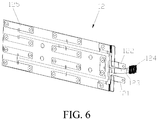
- the battery includes a plurality of cells 11 and a power connecter 125. Two adjacent cells 11 are connected in series or in parallel through the power connecter 125.
- the battery has a positive lead-out end and a negative lead-out end.
- the first end 221 of the first copper bar 22 is electrically connected to the negative lead-out end of the battery, and the first end 241 of the third copper bar 24 is electrically connected to the positive lead-out end of the battery.
- the first end 221 of the first copper bar 22 is electrically connected to the positive lead-out end of the battery, and the first end 241 of the third copper bar 24 is electrically connected to the negative lead-out end of the battery.
- the battery further includes a flexible circuit board 12, the power connecter 125 is disposed on the flexible circuit board 12, and the positive lead-out end and the negative lead-out end of the battery are located on a positive terminal 122 and a negative terminal 121 of the flexible circuit board 12.
- a connecting arm 123 is also formed on the flexible circuit board 12, and an end of the connecting arm 123 is provided with a connector 124 for externally transmitting signals such as a temperature and a voltage of the battery pack 200.
- an opening 212 is formed on the bottom surface of the groove 211.
- the negative terminal 121 of the flexible circuit board 12 passes through the opening 212 to be connected to the first end 221 of the first copper bar 22, the positive terminal 122 of the flexible circuit board 12 passes through the opening 212 to be connected to the first end 241 of the third copper bar 24, and the connecting arm 123 passes through the opening 212 to connect the connector 124 to the information collector 26.
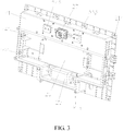
- the battery pack includes a battery, a battery pack housing body, and the battery power lead-out integrated structure as described above.
- the battery is accommodated in the battery pack housing body, the battery pack housing body and an end plate 21 in the battery power lead-out integrated structure 100 constitute a battery pack housing, and the battery includes a plurality of cells 11 and a power connecter 125, two adjacent cells 11 being connected in series or in parallel through the power connecter 125.
- the battery pack housing body is a cuboid with an opening at one end, and the end plate 21 is connected to the opening of the battery pack housing body.
- the battery pack housing body and the end plate 21 may further have other suitable shapes or structures.
- the battery pack housing body may be an integrated structure, or may be a separate structure.
- the battery pack housing body may include an upper housing 30 and a lower housing 40.
- a lower end and a front end of the upper housing 30 are open, and an upper end and a front end of the lower housing 40 are open.
- An edge of the lower end of the upper housing 30 is provided with a fourth mounting hole 31, and an edge of the upper end of the lower housing 40 is provided with a fifth mounting hole 41, the fourth mounting hole 31 and the fifth mounting hole 41 being fixed together by using screws.
- An edge of the front end of the upper housing 30 is provided with a sixth mounting hole 32, an edge of the front end of the lower housing 40 is provided with a seventh mounting hole 42, an edge of the end plate 21 is provided with a third mounting hole 214, the sixth mounting hole 32 and the seventh mounting hole 42 being fixed with the third mounting hole 214 respectively by using screws.
- the vehicle 300 includes the battery pack 200 as described above.
Landscapes
- Chemical & Material Sciences (AREA)
- Chemical Kinetics & Catalysis (AREA)
- Electrochemistry (AREA)
- General Chemical & Material Sciences (AREA)
- Engineering & Computer Science (AREA)
- Combustion & Propulsion (AREA)
- Transportation (AREA)
- Mechanical Engineering (AREA)
- Battery Mounting, Suspending (AREA)
- Connection Of Batteries Or Terminals (AREA)
- Secondary Cells (AREA)
Applications Claiming Priority (2)
| Application Number | Priority Date | Filing Date | Title |
|---|---|---|---|
| CN201810129241.4A CN110137391A (zh) | 2018-02-08 | 2018-02-08 | 电池动力引出集成结构、电池包及车辆 |
| PCT/CN2019/073644 WO2019154176A1 (zh) | 2018-02-08 | 2019-01-29 | 电池动力引出集成结构、电池包及车辆 |
Publications (2)
| Publication Number | Publication Date |
|---|---|
| EP3748712A1 true EP3748712A1 (de) | 2020-12-09 |
| EP3748712A4 EP3748712A4 (de) | 2021-05-12 |
Family
ID=67548212
Family Applications (1)
| Application Number | Title | Priority Date | Filing Date |
|---|---|---|---|
| EP19750601.7A Withdrawn EP3748712A4 (de) | 2018-02-08 | 2019-01-29 | Batterieleistungsgewinnungs- und integrationsstruktur, batteriepack und fahrzeug |
Country Status (6)
| Country | Link |
|---|---|
| US (1) | US20200373542A1 (de) |
| EP (1) | EP3748712A4 (de) |
| JP (1) | JP2021513197A (de) |
| KR (1) | KR20200112934A (de) |
| CN (1) | CN110137391A (de) |
| WO (1) | WO2019154176A1 (de) |
Families Citing this family (6)
| Publication number | Priority date | Publication date | Assignee | Title |
|---|---|---|---|---|
| KR20210126306A (ko) * | 2020-04-10 | 2021-10-20 | 주식회사 엘지에너지솔루션 | 전지 모듈 및 이를 포함하는 전지 팩 |
| CN111785885B (zh) * | 2020-07-23 | 2022-07-19 | 中创新航科技股份有限公司 | 电池组件及电动设备 |
| CN113644388B (zh) * | 2021-08-06 | 2023-08-25 | 广州小鹏汽车科技有限公司 | 铜排及电池包 |
| KR20230050973A (ko) * | 2021-10-08 | 2023-04-17 | 주식회사 엘지에너지솔루션 | 배터리 모듈, 배터리 팩, 및 이를 포함하는 자동차 |
| KR20230067150A (ko) * | 2021-11-09 | 2023-05-16 | 현대자동차주식회사 | 차량의 배터리팩 케이스 |
| KR20230119555A (ko) * | 2022-02-07 | 2023-08-16 | 주식회사 엘지에너지솔루션 | 전지 모듈 |
Family Cites Families (21)
| Publication number | Priority date | Publication date | Assignee | Title |
|---|---|---|---|---|
| EP1030390B1 (de) * | 1997-03-24 | 2004-02-04 | Matsushita Electric Industrial Co., Ltd. | Stromversorgungseinheit enthaltend eine modulare Batterie |
| TW200826340A (en) * | 2006-12-01 | 2008-06-16 | Td Hitech Energy Inc | Battery assembly plate structure and manufacture method thereof |
| JP5477629B2 (ja) * | 2009-12-24 | 2014-04-23 | 株式会社Gsユアサ | 蓄電池用蓋、蓄電池用蓋の射出成形方法、及びその蓄電池用蓋を備えた蓄電池 |
| CN202593301U (zh) * | 2012-04-05 | 2012-12-12 | 郑州宇通客车股份有限公司 | 一种通用化的电动汽车高压安全控制装置 |
| WO2014208020A1 (ja) * | 2013-06-28 | 2014-12-31 | 三洋電機株式会社 | 車載用の電装予備蓄電装置及びこの電装予備蓄電装置を備える車両 |
| CN203631621U (zh) * | 2013-12-05 | 2014-06-04 | 宁德时代新能源科技有限公司 | 电池模组 |
| CN203721834U (zh) * | 2013-12-27 | 2014-07-16 | 上海航天电源技术有限责任公司 | 一种高安全连接结构的锂离子电池模块 |
| KR101737489B1 (ko) * | 2014-06-05 | 2017-05-18 | 주식회사 엘지화학 | 터미널 볼트의 토크 지지 구조가 개선된 배터리 팩 |
| JPWO2016199558A1 (ja) * | 2015-06-12 | 2018-03-29 | 株式会社Gsユアサ | 蓄電装置 |
| CN204956150U (zh) * | 2015-08-19 | 2016-01-13 | 北汽福田汽车股份有限公司 | 车辆电机控制器的集成模块、车辆电机控制器以及车辆 |
| KR102056875B1 (ko) * | 2015-11-10 | 2019-12-17 | 주식회사 엘지화학 | 배터리 모듈 및 이를 포함하는 배터리 팩 |
| CN205429047U (zh) * | 2016-03-22 | 2016-08-03 | 宁德时代新能源科技股份有限公司 | 一种电池模组 |
| CN205621780U (zh) * | 2016-04-07 | 2016-10-05 | 中国第一汽车股份有限公司 | 一种液冷动力电池端板总成 |
| CN205723706U (zh) * | 2016-05-06 | 2016-11-23 | 宁德时代新能源科技股份有限公司 | 低压动力电池包 |
| CN206422164U (zh) * | 2016-12-19 | 2017-08-18 | 河北银隆新能源有限公司 | 一种包覆式电池模组结构 |
| CN206461001U (zh) * | 2017-01-23 | 2017-09-01 | 合肥国轩高科动力能源有限公司 | 一种中间带加强结构的电池模组 |
| CN206471396U (zh) * | 2017-02-28 | 2017-09-05 | 长城汽车股份有限公司 | 动力电池包 |
| CN206628507U (zh) * | 2017-04-01 | 2017-11-10 | 合肥国轩高科动力能源有限公司 | 一种电池模组的集成盖板 |
| CN107425167A (zh) * | 2017-08-09 | 2017-12-01 | 深圳市锐拓新源科技有限公司 | 一种电池模组 |
| US10003112B1 (en) * | 2017-12-01 | 2018-06-19 | GM Global Technology Operations LLC | Battery backplane assembly with integrated bus bar connections and thermal management features |
| CN208298881U (zh) * | 2018-02-08 | 2018-12-28 | 比亚迪股份有限公司 | 动力电池包及车辆 |
-
2018
- 2018-02-08 CN CN201810129241.4A patent/CN110137391A/zh active Pending
-
2019
- 2019-01-29 US US16/968,700 patent/US20200373542A1/en not_active Abandoned
- 2019-01-29 WO PCT/CN2019/073644 patent/WO2019154176A1/zh unknown
- 2019-01-29 EP EP19750601.7A patent/EP3748712A4/de not_active Withdrawn
- 2019-01-29 KR KR1020207024411A patent/KR20200112934A/ko not_active Application Discontinuation
- 2019-01-29 JP JP2020542734A patent/JP2021513197A/ja active Pending
Also Published As
| Publication number | Publication date |
|---|---|
| WO2019154176A1 (zh) | 2019-08-15 |
| EP3748712A4 (de) | 2021-05-12 |
| KR20200112934A (ko) | 2020-10-05 |
| CN110137391A (zh) | 2019-08-16 |
| US20200373542A1 (en) | 2020-11-26 |
| JP2021513197A (ja) | 2021-05-20 |
Similar Documents
| Publication | Publication Date | Title |
|---|---|---|
| EP3748712A1 (de) | Batterieleistungsgewinnungs- und integrationsstruktur, batteriepack und fahrzeug | |
| KR102233776B1 (ko) | 배터리모듈 | |
| JP2018018795A (ja) | 電池パック | |
| US20180123161A1 (en) | Secondary battery | |
| KR101724006B1 (ko) | 이차 전지 | |
| KR101684349B1 (ko) | 보호회로모듈 케이스를 포함하는 전지팩 | |
| CN103797617A (zh) | 具有新型结构的顶盖组件 | |
| CN212303783U (zh) | 连接式盖板组件及动力电池 | |
| CN102082241B (zh) | 二次电池 | |
| US10818958B2 (en) | Battery cell and battery system | |
| WO2019113970A1 (zh) | 纽扣电池及其制作方法 | |
| EP4087013A1 (de) | Batterie, batteriemodul, batteriepack und elektrofahrzeug | |
| KR101619926B1 (ko) | 보호회로모듈 케이스를 포함하는 전지팩 | |
| CN112234296B (zh) | 电芯以及电池模组 | |
| CN220368025U (zh) | 电芯组件及电池 | |
| EP3790080B1 (de) | Batteriemodul und batteriesatz | |
| CN219180724U (zh) | 一种电池、电池包及用电设备 | |
| CN111668435A (zh) | 车载电池和具有其的车辆 | |
| CN205828526U (zh) | 转接组件 | |
| US10461305B2 (en) | Battery cell and battery system | |
| CN111668434B (zh) | 电池模组和具有其的车辆 | |
| CN214477672U (zh) | 电池盖板组件、单体电池、电池包及电动车辆 | |
| KR20140100038A (ko) | 보호회로모듈 고정부를 포함하는 전지팩 | |
| CN111668407B (zh) | 电池模组和具有其的车辆 | |
| CN217823166U (zh) | 一种电源装置 |
Legal Events
| Date | Code | Title | Description |
|---|---|---|---|
| STAA | Information on the status of an ep patent application or granted ep patent |
Free format text: STATUS: THE INTERNATIONAL PUBLICATION HAS BEEN MADE |
|
| PUAI | Public reference made under article 153(3) epc to a published international application that has entered the european phase |
Free format text: ORIGINAL CODE: 0009012 |
|
| STAA | Information on the status of an ep patent application or granted ep patent |
Free format text: STATUS: REQUEST FOR EXAMINATION WAS MADE |
|
| 17P | Request for examination filed |
Effective date: 20200903 |
|
| AK | Designated contracting states |
Kind code of ref document: A1 Designated state(s): AL AT BE BG CH CY CZ DE DK EE ES FI FR GB GR HR HU IE IS IT LI LT LU LV MC MK MT NL NO PL PT RO RS SE SI SK SM TR |
|
| AX | Request for extension of the european patent |
Extension state: BA ME |
|
| A4 | Supplementary search report drawn up and despatched |
Effective date: 20210412 |
|
| DAV | Request for validation of the european patent (deleted) | ||
| DAX | Request for extension of the european patent (deleted) | ||
| RIC1 | Information provided on ipc code assigned before grant |
Ipc: H01M 50/50 20210101AFI20210406BHEP Ipc: H01M 50/20 20210101ALI20210406BHEP Ipc: H01M 50/278 20210101ALI20210406BHEP Ipc: H01M 50/503 20210101ALI20210406BHEP Ipc: H01M 50/545 20210101ALI20210406BHEP |
|
| STAA | Information on the status of an ep patent application or granted ep patent |
Free format text: STATUS: THE APPLICATION IS DEEMED TO BE WITHDRAWN |
|
| 18D | Application deemed to be withdrawn |
Effective date: 20211111 |