EP3745196B1 - Camera module - Google Patents
Camera module Download PDFInfo
- Publication number
- EP3745196B1 EP3745196B1 EP20186849.4A EP20186849A EP3745196B1 EP 3745196 B1 EP3745196 B1 EP 3745196B1 EP 20186849 A EP20186849 A EP 20186849A EP 3745196 B1 EP3745196 B1 EP 3745196B1
- Authority
- EP
- European Patent Office
- Prior art keywords
- holder
- printed circuit
- circuit board
- camera module
- hole
- Prior art date
- Legal status (The legal status is an assumption and is not a legal conclusion. Google has not performed a legal analysis and makes no representation as to the accuracy of the status listed.)
- Active
Links
Images

Classifications
-
- G—PHYSICS
- G03—PHOTOGRAPHY; CINEMATOGRAPHY; ANALOGOUS TECHNIQUES USING WAVES OTHER THAN OPTICAL WAVES; ELECTROGRAPHY; HOLOGRAPHY
- G03B—APPARATUS OR ARRANGEMENTS FOR TAKING PHOTOGRAPHS OR FOR PROJECTING OR VIEWING THEM; APPARATUS OR ARRANGEMENTS EMPLOYING ANALOGOUS TECHNIQUES USING WAVES OTHER THAN OPTICAL WAVES; ACCESSORIES THEREFOR
- G03B1/00—Film strip handling
- G03B1/02—Moving film strip by pull on end thereof
-
- G—PHYSICS
- G03—PHOTOGRAPHY; CINEMATOGRAPHY; ANALOGOUS TECHNIQUES USING WAVES OTHER THAN OPTICAL WAVES; ELECTROGRAPHY; HOLOGRAPHY
- G03B—APPARATUS OR ARRANGEMENTS FOR TAKING PHOTOGRAPHS OR FOR PROJECTING OR VIEWING THEM; APPARATUS OR ARRANGEMENTS EMPLOYING ANALOGOUS TECHNIQUES USING WAVES OTHER THAN OPTICAL WAVES; ACCESSORIES THEREFOR
- G03B17/00—Details of cameras or camera bodies; Accessories therefor
- G03B17/02—Bodies
- G03B17/12—Bodies with means for supporting objectives, supplementary lenses, filters, masks, or turrets
-
- H—ELECTRICITY
- H04—ELECTRIC COMMUNICATION TECHNIQUE
- H04N—PICTORIAL COMMUNICATION, e.g. TELEVISION
- H04N23/00—Cameras or camera modules comprising electronic image sensors; Control thereof
-
- H—ELECTRICITY
- H04—ELECTRIC COMMUNICATION TECHNIQUE
- H04N—PICTORIAL COMMUNICATION, e.g. TELEVISION
- H04N23/00—Cameras or camera modules comprising electronic image sensors; Control thereof
- H04N23/40—Circuit details for pick-up tubes
-
- H—ELECTRICITY
- H04—ELECTRIC COMMUNICATION TECHNIQUE
- H04N—PICTORIAL COMMUNICATION, e.g. TELEVISION
- H04N23/00—Cameras or camera modules comprising electronic image sensors; Control thereof
- H04N23/50—Constructional details
- H04N23/51—Housings
-
- H—ELECTRICITY
- H04—ELECTRIC COMMUNICATION TECHNIQUE
- H04N—PICTORIAL COMMUNICATION, e.g. TELEVISION
- H04N23/00—Cameras or camera modules comprising electronic image sensors; Control thereof
- H04N23/50—Constructional details
- H04N23/54—Mounting of pick-up tubes, electronic image sensors, deviation or focusing coils
-
- H—ELECTRICITY
- H04—ELECTRIC COMMUNICATION TECHNIQUE
- H04N—PICTORIAL COMMUNICATION, e.g. TELEVISION
- H04N23/00—Cameras or camera modules comprising electronic image sensors; Control thereof
- H04N23/50—Constructional details
- H04N23/55—Optical parts specially adapted for electronic image sensors; Mounting thereof
Definitions
- Camera modules may be mounted in vehicles for various purposes.
- a camera module which is capable of securing the view behind a vehicle when parking the vehicle, may be mounted on the rear of the vehicle.
- a camera module may also be used in a vehicle black box, which is very useful in tracking details of an accident, the reason of an accident, and the like when a traffic accident occurs.
- a camera module is used as a recognition device for clearly and easily grasping the situation in a blind spot, which is difficult to see with the naked eye by a vehicle driver or a passenger.
- a so-called “smart car” i.e. a vehicle equipped with, for example, a collision warning system for detecting in advance the possibility of a collision ahead of or behind the vehicle while driving to prepare for the collision or a collision avoidance system for allowing a control device mounted in the vehicle to directly avoid a collision between vehicles that are driving, without intervention by a driver, has recently gradually increased, and the development of related technologies is increasing.
- a camera module may be configured such that a lens and an image sensor are disposed at opposite positions in an optical-axis direction. When assembling the camera module, the lens and the image sensor are disposed so that the focal distance therebetween is within a design range.
- the focal distance may deviate from the design range in the process of assembling the camera module, which is a problem that this needs to be solved.
- embodiments relate to a camera module having a structure that is capable of preventing the focal distance between a lens and an image sensor from deviating from a design range in an assembly process or preventing some elements from being deformed or damaged, and that is also capable of allowing the lens and the image sensor to be aligned parallel to each other.
- a camera module includes a lens barrel having at least one lens, a holder coupled to the lens barrel, a printed circuit board coupled to a lower portion of the holder so as to face the lens, an adhesive element configured to couple the holder and the printed circuit board to each other, an opening configured to open a portion of a first space, which is defined via coupling of the printed circuit board and the holder, and a housing coupled to the holder, wherein the first space is separated from a second space, which is defined via coupling of the holder and the housing, and wherein the first space and the second space communicate with each other through the opening.
- the printed circuit board may be coupled to an image sensor, and the image sensor may be disposed in the first space.
- the adhesive element may have one side surface disposed so as to be exposed to the second space.
- a coupling portion of the holder and the housing may be disposed closer to the lens than the adhesive element in a first direction.
- the adhesive element may overlap the housing in a direction orthogonal to a first direction.
- the opening may be provided as a first through-hole formed in one side of the adhesive element.
- the opening may be provided as a second through-hole formed in the printed circuit board in a first direction.
- the second through-hole may be formed inside a curved line, which is defined by the adhesive element.
- the opening may be provided as a third through-hole formed in the lower portion of the holder so as to penetrate the holder in a lateral direction.
- the opening may be closed after the holder and the printed circuit board are completely coupled to each other.
- the camera module may further include a packing member mounted in a coupling region of the lens barrel and the holder.
- a camera module includes a lens barrel having at least one lens, a holder coupled to the lens barrel, a printed circuit board coupled to a lower portion of the holder so as to face the lens, a housing coupled to the holder and configured to accommodate the printed circuit board therein, an opening configured to open a portion of a first space, which is defined via coupling of the holder and the printed circuit board, and an adhesive element coupling to a lower surface of the holder and an upper surface of the printed circuit board so as to couple the holder and the printed circuit board to each other, wherein the opening is formed in at least one region of one side of the adhesive element, the printed circuit board, or the lower portion of the holder.
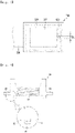
- a camera module includes a printed circuit board, an image sensor mounted on the printed circuit board, a holder disposed on the printed circuit board so as to accommodate the image sensor therein and having a first fastening portion and a second fastening portion, which are formed respectively on opposite side surfaces thereof and have a first fastening reference hole and a second fastening reference hole respectively, and a through-hole formed above the image sensor, and a lens barrel fastened to an upper region of the through-hole so as to face the image sensor, wherein the printed circuit board is tilted so that a horizontal plane, which passes through a center of the first fastening reference hole and a center of the second fastening reference hole is parallel to an upper surface of the image sensor, and wherein the horizontal plane, which passes through the center of the first fastening reference hole and the center of the second fastening reference hole, is parallel to an upper surface of a lens mounted in the lens barrel.
- the lens barrel may include a protrusion configured to protrude from an outer circumferential surface thereof in a ring form so as to bond to an upper surface of the holder.
- the camera module may further include a first adhesive member disposed between a lower end surface of the protrusion and the upper surface of the holder, which faces the protrusion.
- the holder may have a lower surface, which faces the printed circuit board, and the camera module may further include a second adhesive member disposed between a bonding surface of the lower surface, which is adjacent to the through-hole, and the printed circuit board.
- the camera module may further include a partition disposed between the bonding surface and the through-hole.
- the partition may protrude from the lower surface of the holder toward the printed circuit board.
- the partition may protrude from an upper surface of the printed circuit board toward the lower surface of the holder.
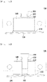
- the bonding surface may have an inclined cross-sectional shape, and a height of a space between the bonding surface of an upper surface of the printed circuit board may increase with increasing distance from the through-hole.
- malfunction of the camera module may be prevented, as a result of preventing a change in the focal distance of the camera module beyond a design range, damage to the adhesive element or the printed circuit board, and the like.
- relative terms such as, for example, “first”, “second”, “on/upper/above” and “beneath/lower/below”, used in the following description may be used to distinguish any one substance or element with another substance or element without requiring or containing any physical or logical relationship or sequence between these substances or elements.
- the orthogonal coordinate system (x, y, z) may be used in the drawings.
- the x-axis and the y-axis indicate planes orthogonal to the optical axis, and for convenience, the optical axis direction (the z-axis) is referred to as a first direction, the x-axis is referred to as a second direction, and the y-axis is referred to as a third direction.
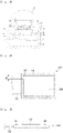
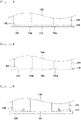
- FIG. 1 is a side view illustrating a lens barrel 100 according to a first embodiment.
- FIG. 2 is a side cross-sectional view illustrating a holder 200 according to the first embodiment.
- FIG. 3 is a side cross-sectional view illustrating a camera module according to the first embodiment.
- the holder 200 may have a hollow region formed therein.
- the hollow region may have a shape corresponding to the outer shape of the lens barrel 100.
- the holder 200 and the lens barrel 100 may be coupled to each other when a portion of the lens barrel 100 is inserted into the hollow region.
- the holder and the printed circuit board which have been primarily aligned with each other, may be attached and fixed to each other via a second adhesive member, which will be described later.
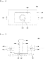
- the printed circuit board may be tilted so that the horizontal plane, which passes through the center O of the first fastening reference hole and the center O' of the second fastening reference hole, the upper surface of the image sensor 1400, and the upper surface of the lens are parallel to one another and so that the image sensor 140 is parallel to the horizontal plane, which passes through the center O of the first fastening reference hole and the center O' of the second fastening reference hole, and in such a tilted state of the printed circuit board, the camera module may be mounted at a desired mounting position thereof.
- the second adhesive member may be formed of an ultraviolet-curable adhesive, which may be solidified within a short time via a reaction of a light reaction initiator contained in a liquid-phase adhesive by irradiating the adhesive with ultraviolet light, without limitation thereto.
- the partition 1700a may be disposed so as to protrude from the lower surface of the holder 1600 toward the printed circuit board 1200, and may be formed in a ring shape so that the inner diameter thereof is equal to or greater than the inner diameter of the through-hole 1660.
- the inner diameter of the partition 1700a is much greater than the inner diameter of the through-hole 1660, the area over which the second adhesive member is disposed between the bonding surface 1680 of the holder 1600 and the printed circuit board 1200 may be reduced, which may deteriorate adhesive force. Therefore, the partition may be disposed at a position at which deterioration in adhesive force may not occur.
- the partition 1700b may be disposed so as to protrude from the upper surface of the printed circuit board 1200 toward the lower surface of the holder.
- the partition 1700b may be formed in a ring shape such that the inner diameter thereof is equal to or greater than the inner diameter of the through-hole 1660 in the holder.
- the partition 1700a may be formed such that the side cross section of the partition 1700a has an oval shape to enable the tilting of the printed circuit board 1200, without the limitation thereto.
- the bonding surface 1680 may have roughness, which may increase the adhesive force of the bonding surface and the second adhesive member.
- the magnitude of roughness may range from 1 ⁇ m to 5 ⁇ m , the magnitude of roughness may be changed depending on the area or material of the bonding surface of the holder 1600.
- the inclined bonding surface 1680 may be provided and the partition 1700a may protrude from the lower surface of the holder 1600 toward the printed circuit board 1200.
- the inclined bonding surface 1680 may be provided and the partition 1700b may protrude from the upper surface of the printed circuit board 1200 toward the lower surface of the holder 1600.
- the lens and the image sensor are fastened so as to be parallel to each other, it is possible to acquire an accurate image, which is not distorted and is the same as an actual image, from each camera module without the influence of the position at which the camera module is mounted.
- malfunction of a camera module may be prevented by preventing, for example, damage to an adhesive element or a printed circuit board.
- a lens and an image sensor are fastened so as to be parallel to each other, it is possible to manufacture the camera module, which is capable of acquiring an accurate image, which is not distorted and is the same as an actual image, from each camera module without the influence of the position at which the camera module is mounted.
- the camera module may be applied to, for example, a mobile communication terminal.
Landscapes
- Engineering & Computer Science (AREA)
- Multimedia (AREA)
- Signal Processing (AREA)
- Physics & Mathematics (AREA)
- General Physics & Mathematics (AREA)
- Lens Barrels (AREA)
- Studio Devices (AREA)
- Camera Bodies And Camera Details Or Accessories (AREA)
Priority Applications (2)
| Application Number | Priority Date | Filing Date | Title |
|---|---|---|---|
| EP22200666.0A EP4141539B1 (en) | 2015-06-08 | 2016-06-08 | Camera module |
| EP24213351.0A EP4488751A3 (en) | 2015-06-08 | 2016-06-08 | Camera module |
Applications Claiming Priority (4)
| Application Number | Priority Date | Filing Date | Title |
|---|---|---|---|
| KR1020150080414A KR102344460B1 (ko) | 2015-06-08 | 2015-06-08 | 카메라 모듈 |
| KR1020160017308A KR101943449B1 (ko) | 2016-02-15 | 2016-02-15 | 카메라 모듈 |
| PCT/KR2016/006030 WO2016200126A1 (ko) | 2015-06-08 | 2016-06-08 | 카메라 모듈 |
| EP16807766.7A EP3306907B1 (en) | 2015-06-08 | 2016-06-08 | Camera module |
Related Parent Applications (2)
| Application Number | Title | Priority Date | Filing Date |
|---|---|---|---|
| EP16807766.7A Division-Into EP3306907B1 (en) | 2015-06-08 | 2016-06-08 | Camera module |
| EP16807766.7A Division EP3306907B1 (en) | 2015-06-08 | 2016-06-08 | Camera module |
Related Child Applications (3)
| Application Number | Title | Priority Date | Filing Date |
|---|---|---|---|
| EP24213351.0A Division EP4488751A3 (en) | 2015-06-08 | 2016-06-08 | Camera module |
| EP22200666.0A Division EP4141539B1 (en) | 2015-06-08 | 2016-06-08 | Camera module |
| EP22200666.0A Division-Into EP4141539B1 (en) | 2015-06-08 | 2016-06-08 | Camera module |
Publications (2)
| Publication Number | Publication Date |
|---|---|
| EP3745196A1 EP3745196A1 (en) | 2020-12-02 |
| EP3745196B1 true EP3745196B1 (en) | 2022-11-16 |
Family
ID=57503747
Family Applications (4)
| Application Number | Title | Priority Date | Filing Date |
|---|---|---|---|
| EP20186849.4A Active EP3745196B1 (en) | 2015-06-08 | 2016-06-08 | Camera module |
| EP16807766.7A Active EP3306907B1 (en) | 2015-06-08 | 2016-06-08 | Camera module |
| EP22200666.0A Active EP4141539B1 (en) | 2015-06-08 | 2016-06-08 | Camera module |
| EP24213351.0A Pending EP4488751A3 (en) | 2015-06-08 | 2016-06-08 | Camera module |
Family Applications After (3)
| Application Number | Title | Priority Date | Filing Date |
|---|---|---|---|
| EP16807766.7A Active EP3306907B1 (en) | 2015-06-08 | 2016-06-08 | Camera module |
| EP22200666.0A Active EP4141539B1 (en) | 2015-06-08 | 2016-06-08 | Camera module |
| EP24213351.0A Pending EP4488751A3 (en) | 2015-06-08 | 2016-06-08 | Camera module |
Country Status (5)
| Country | Link |
|---|---|
| US (5) | US10498937B2 (enExample) |
| EP (4) | EP3745196B1 (enExample) |
| JP (1) | JP7020921B2 (enExample) |
| CN (3) | CN113296333B (enExample) |
| WO (1) | WO2016200126A1 (enExample) |
Families Citing this family (20)
| Publication number | Priority date | Publication date | Assignee | Title |
|---|---|---|---|---|
| EP3745196B1 (en) | 2015-06-08 | 2022-11-16 | Lg Innotek Co. Ltd | Camera module |
| KR102647850B1 (ko) * | 2016-11-21 | 2024-03-15 | 엘지이노텍 주식회사 | 카메라 모듈 |
| CN109639936B (zh) * | 2017-10-09 | 2022-01-21 | 法雷奥汽车内部控制(深圳)有限公司 | 相机模块及其安装方法 |
| US20190219897A1 (en) * | 2018-01-17 | 2019-07-18 | Integrated Micro-Electronics, Inc. | Optically Aligned Camera Module Assembly Using Soldering |
| KR102492626B1 (ko) * | 2018-03-20 | 2023-01-27 | 엘지이노텍 주식회사 | 카메라 모듈 및 이를 포함하는 광학 기기 |
| KR102511623B1 (ko) * | 2018-04-11 | 2023-03-20 | 엘지이노텍 주식회사 | 카메라 모듈 |
| FR3082634B1 (fr) * | 2018-06-18 | 2021-10-01 | Delphi Tech Llc | Dispositif optique pour vehicule comprenant un element de chauffage |
| FR3082633B1 (fr) | 2018-06-18 | 2021-10-01 | Delphi Tech Llc | Dispositif optique pour vehicule comprenant un element de chauffage |
| USD879181S1 (en) * | 2018-07-06 | 2020-03-24 | Actron Technology Corporation | Lens holder of automobile surveillance camera |
| DE102018213146A1 (de) * | 2018-08-07 | 2020-02-13 | Robert Bosch Gmbh | Leiterplattenvorrichtung für ein Bildaufnehmermodul für eine Kamera, Bildaufnehmermodul mit einer Leiterplattenvorrichtung und Verfahren zum Herstellen einer Leiterplattenvorrichtung |
| CN109343298B (zh) * | 2018-12-25 | 2023-11-24 | 浙江舜宇智领技术有限公司 | 一种摄像模组 |
| CN110351469B (zh) * | 2019-07-29 | 2020-05-12 | 江西联益光学有限公司 | 一种摄像头模组及其组装工艺 |
| US11199758B2 (en) * | 2019-08-05 | 2021-12-14 | Magna Electronics Inc. | Vehicular camera assembly process with dual focusing feature |
| DE102020202784A1 (de) * | 2019-09-18 | 2021-03-18 | Robert Bosch Gesellschaft mit beschränkter Haftung | Verfahren zum Herstellen eines Kameramoduls |
| JP7242500B2 (ja) * | 2019-10-18 | 2023-03-20 | 日立Astemo株式会社 | ステレオカメラ装置 |
| KR102902591B1 (ko) * | 2019-11-12 | 2025-12-22 | 엘지이노텍 주식회사 | 카메라 모듈 |
| KR102380310B1 (ko) * | 2020-08-26 | 2022-03-30 | 삼성전기주식회사 | 카메라 모듈 |
| JP2022038900A (ja) * | 2020-08-27 | 2022-03-10 | パナソニックIpマネジメント株式会社 | 撮像モジュール、撮像モジュールの製造方法および撮像装置 |
| DE102022117603A1 (de) | 2022-07-14 | 2024-01-25 | Connaught Electronics Ltd. | Fahrzeugkamera, Verfahren zum Montieren einer Fahrzeugkamera sowie Fahrzeug mit einer Fahrzeugkamera |
| KR20240066794A (ko) | 2022-11-08 | 2024-05-16 | 삼성전기주식회사 | 카메라 모듈 |
Family Cites Families (67)
| Publication number | Priority date | Publication date | Assignee | Title |
|---|---|---|---|---|
| JPS56106230A (en) * | 1980-01-30 | 1981-08-24 | Nitto Kogaku Kk | Optical system cover device of camera |
| CN2240156Y (zh) * | 1995-01-16 | 1996-11-13 | 宛晓 | 立体照像机 |
| TW528889B (en) * | 2000-11-14 | 2003-04-21 | Toshiba Corp | Image pickup apparatus, manufacturing method thereof, and portable electric apparatus |
| DE10162652A1 (de) * | 2001-12-20 | 2003-07-03 | Bosch Gmbh Robert | Stereo-Kamera-Anordnung in einem Kraftfahrzeug |
| US7061699B2 (en) * | 2002-03-28 | 2006-06-13 | Seiko Epson Corporation | Projection lens, producing method of projection lens and projector having projection lens |
| JP2003318585A (ja) * | 2002-04-24 | 2003-11-07 | Toshiba Corp | 電子機器 |
| JP4223851B2 (ja) * | 2003-03-31 | 2009-02-12 | ミツミ電機株式会社 | 小型カメラモジュール |
| JP4387702B2 (ja) * | 2003-06-24 | 2009-12-24 | キヤノン株式会社 | レンズ鏡筒 |
| DE10344762B4 (de) * | 2003-09-26 | 2006-06-29 | Siemens Ag | Optisches Modul mit auf der sensitiven Fläche abgestützter Linseneinheit und optisches System |
| DE10344768B3 (de) * | 2003-09-26 | 2005-08-18 | Siemens Ag | Optisches Modul mit federndem Element zwischen Linsenhalter und Schaltungsträger und optisches System |
| KR100674911B1 (ko) * | 2004-08-06 | 2007-01-26 | 삼성전자주식회사 | 이미지 센서 카메라 모듈 및 그 제조방법 |
| JP5055817B2 (ja) * | 2005-06-08 | 2012-10-24 | マックス株式会社 | 打込み工具におけるコンタクト機構 |
| CN101218653A (zh) * | 2005-07-07 | 2008-07-09 | 皇家飞利浦电子股份有限公司 | 致动器组件以及驱动致动器组件的方法和设备 |
| US7539412B2 (en) * | 2006-05-17 | 2009-05-26 | Terrasem Co. Ltd. | Camera module with first and second image sensor chips, holders and lens |
| KR100818467B1 (ko) | 2006-08-11 | 2008-04-01 | 삼성전기주식회사 | 카메라 모듈 패키지 |
| KR100831710B1 (ko) | 2006-08-17 | 2008-05-22 | 삼성전기주식회사 | 카메라 모듈의 조립 장치 및 그 조립 방법 |
| JP4930989B2 (ja) * | 2006-11-30 | 2012-05-16 | 日立マクセル株式会社 | カメラモジュール及び撮像装置 |
| KR20080095354A (ko) * | 2007-04-24 | 2008-10-29 | 삼성전기주식회사 | 카메라 모듈용 수지기판과 그 제조 방법, 그리고 이를 포함하는 카메라 모듈과 그 제조방법 |
| US8493658B2 (en) * | 2007-07-06 | 2013-07-23 | Semiconductor Energy Laboratory Co., Ltd. | Polarizer and display device including polarizer |
| US8564716B2 (en) * | 2007-11-21 | 2013-10-22 | Lg Innotek Co., Ltd. | Camera module |
| JP2009130220A (ja) * | 2007-11-26 | 2009-06-11 | Sharp Corp | 固体撮像装置およびその製造方法 |
| JP2009188720A (ja) * | 2008-02-06 | 2009-08-20 | Panasonic Corp | 固体撮像装置およびその製造方法 |
| JP2009265473A (ja) * | 2008-04-28 | 2009-11-12 | Konica Minolta Opto Inc | レンズ、撮像レンズ及び撮像装置 |
| JP4666005B2 (ja) * | 2008-05-30 | 2011-04-06 | ソニー株式会社 | カメラ装置 |
| KR100973004B1 (ko) * | 2008-06-10 | 2010-07-30 | 삼성전기주식회사 | 카메라 모듈 |
| US8054639B2 (en) * | 2008-12-01 | 2011-11-08 | Azurewave Technologies, Inc. | Image-sensing module for reducing overall thickness thereof and preventing EMI |
| KR101567069B1 (ko) | 2008-12-23 | 2015-11-06 | 엘지이노텍 주식회사 | 카메라 모듈 |
| JP2010199735A (ja) | 2009-02-23 | 2010-09-09 | Ricoh Co Ltd | カメラユニット及びカメラユニットの製造方法 |
| KR20100100063A (ko) | 2009-03-05 | 2010-09-15 | 삼성전기주식회사 | 카메라 모듈 |
| ES2820225T3 (es) | 2009-03-25 | 2021-04-20 | Magna Electronics Inc | Montaje de cámara y lente vehicular |
| TWI391083B (zh) * | 2010-05-14 | 2013-03-21 | Altek Corp | 支架及具有該支架之攝像裝置 |
| KR101055449B1 (ko) | 2009-09-03 | 2011-08-08 | 삼성전기주식회사 | 카메라 모듈 |
| CN102025899B (zh) | 2009-09-11 | 2013-11-06 | 鸿富锦精密工业(深圳)有限公司 | 相机模组及其组装方法 |
| KR20110068419A (ko) * | 2009-12-16 | 2011-06-22 | 삼성전기주식회사 | 카메라모듈 |
| JP5017406B2 (ja) * | 2010-03-24 | 2012-09-05 | 株式会社東芝 | カメラモジュール |
| CN102279453A (zh) * | 2010-06-11 | 2011-12-14 | 鸿富锦精密工业(深圳)有限公司 | 镜头模组及相机装置 |
| KR101175869B1 (ko) | 2010-08-18 | 2012-08-21 | 삼성전기주식회사 | 카메라 모듈 |
| TW201210005A (en) * | 2010-08-23 | 2012-03-01 | Shu-Zi Chen | Thinning of the image capturing module and manufacturing method thereof |
| JP2012059881A (ja) * | 2010-09-08 | 2012-03-22 | Toshiba Corp | 撮像素子、撮像モジュール及び撮像素子の製造方法 |
| KR101779498B1 (ko) * | 2010-11-16 | 2017-09-18 | 엘지이노텍 주식회사 | 카메라 모듈 |
| US8891007B2 (en) * | 2011-03-07 | 2014-11-18 | Digitaloptics Corporation | Camera module with protective air ventilation channel |
| DE102011005629A1 (de) * | 2011-03-16 | 2012-09-20 | Robert Bosch Gmbh | Bildsensor-Modul und Verfahren zum Herstellen eines solchen |
| JP5725989B2 (ja) * | 2011-06-14 | 2015-05-27 | 京セラ株式会社 | 撮像モジュール |
| WO2013048180A1 (en) * | 2011-09-30 | 2013-04-04 | Lg Innotek Co., Ltd. | Camera module |
| US8698952B2 (en) * | 2011-10-31 | 2014-04-15 | Lg Innotek Co., Ltd. | Camera module |
| KR101845089B1 (ko) * | 2011-11-23 | 2018-04-03 | 엘지이노텍 주식회사 | 카메라 모듈 |
| KR101875419B1 (ko) | 2011-11-29 | 2018-07-06 | 엘지이노텍 주식회사 | 카메라 모듈 및 그의 조립 방법 |
| WO2014126275A1 (ko) | 2013-02-14 | 2014-08-21 | Kim Young Jun | 렌즈 액츄에이터, 카메라 모듈 및 그 제조 방법 |
| JP2014170893A (ja) * | 2013-03-05 | 2014-09-18 | Taiyo Yuden Co Ltd | カメラモジュール |
| KR101444024B1 (ko) | 2013-05-15 | 2014-09-23 | 삼성전기주식회사 | 차량용 카메라모듈 |
| KR102128502B1 (ko) * | 2013-07-04 | 2020-06-30 | 엘지이노텍 주식회사 | 카메라 모듈 |
| KR102117107B1 (ko) * | 2013-07-12 | 2020-05-29 | 엘지이노텍 주식회사 | 카메라 모듈 |
| KR102145831B1 (ko) | 2013-11-05 | 2020-08-19 | 엘지이노텍 주식회사 | 카메라 모듈 |
| US10194062B2 (en) * | 2013-10-16 | 2019-01-29 | Samsung Electro-Mechanics Co., Ltd. | Camera module, method for aligning optical axis of camera module and portable electronic device including camera module |
| US9451138B2 (en) * | 2013-11-07 | 2016-09-20 | Magna Electronics Inc. | Camera for vehicle vision system |
| KR20150066804A (ko) * | 2013-12-09 | 2015-06-17 | 삼성전기주식회사 | 카메라 모듈 |
| KR20150092867A (ko) * | 2014-02-06 | 2015-08-17 | 삼성전기주식회사 | 카메라 모듈 |
| US10122902B2 (en) * | 2014-05-07 | 2018-11-06 | Gopro, Inc. | Integrated image sensor and lens assembly |
| US10031401B2 (en) * | 2014-05-19 | 2018-07-24 | Sharp Kabushiki Kaisha | Camera module and electronic device |
| US9578217B2 (en) * | 2014-05-27 | 2017-02-21 | Mems Drive, Inc. | Moving image sensor package |
| WO2016047354A1 (ja) * | 2014-09-25 | 2016-03-31 | 日本電産コパル株式会社 | 撮像装置、光学機器、電子機器、車両および撮像装置の製造方法 |
| KR102390760B1 (ko) * | 2015-02-13 | 2022-04-26 | 삼성전자주식회사 | 카메라 장치 및 이를 구비한 전자 장치 |
| US9930233B2 (en) * | 2015-04-22 | 2018-03-27 | Light Labs Inc. | Filter mounting methods and apparatus and related camera apparatus |
| EP3745196B1 (en) * | 2015-06-08 | 2022-11-16 | Lg Innotek Co. Ltd | Camera module |
| US10602039B2 (en) * | 2016-09-19 | 2020-03-24 | Microsoft Technology Licensing, Llc | Ultra-compact image sensor assembly for thin profile devices |
| TWI600928B (zh) * | 2016-09-30 | 2017-10-01 | 光寶電子(廣州)有限公司 | 濾光片總成及具有該濾光片總成的相機模組 |
| US10241240B1 (en) * | 2017-12-06 | 2019-03-26 | Lg Innotek Co., Ltd. | Lens assembly and camera module including the lens assembly |
-
2016
- 2016-06-08 EP EP20186849.4A patent/EP3745196B1/en active Active
- 2016-06-08 WO PCT/KR2016/006030 patent/WO2016200126A1/ko not_active Ceased
- 2016-06-08 EP EP16807766.7A patent/EP3306907B1/en active Active
- 2016-06-08 EP EP22200666.0A patent/EP4141539B1/en active Active
- 2016-06-08 CN CN202110523175.0A patent/CN113296333B/zh active Active
- 2016-06-08 EP EP24213351.0A patent/EP4488751A3/en active Pending
- 2016-06-08 US US15/735,076 patent/US10498937B2/en active Active
- 2016-06-08 CN CN202110523211.3A patent/CN113296334B/zh active Active
- 2016-06-08 CN CN201680033459.9A patent/CN107735726B/zh active Active
- 2016-06-08 JP JP2017563582A patent/JP7020921B2/ja active Active
-
2019
- 2019-10-28 US US16/665,420 patent/US10911655B2/en active Active
-
2020
- 2020-12-28 US US17/135,149 patent/US11470231B2/en active Active
-
2022
- 2022-09-06 US US17/929,913 patent/US11882350B2/en active Active
-
2023
- 2023-12-18 US US18/543,811 patent/US20240121494A1/en active Pending
Also Published As
| Publication number | Publication date |
|---|---|
| US20220417400A1 (en) | 2022-12-29 |
| EP4141539A1 (en) | 2023-03-01 |
| CN113296333A (zh) | 2021-08-24 |
| EP3306907B1 (en) | 2020-08-26 |
| US20210120155A1 (en) | 2021-04-22 |
| US10911655B2 (en) | 2021-02-02 |
| CN107735726A (zh) | 2018-02-23 |
| CN113296333B (zh) | 2022-09-27 |
| US11882350B2 (en) | 2024-01-23 |
| US20200068101A1 (en) | 2020-02-27 |
| JP2018518712A (ja) | 2018-07-12 |
| CN107735726B (zh) | 2021-06-01 |
| US11470231B2 (en) | 2022-10-11 |
| US10498937B2 (en) | 2019-12-03 |
| US20240121494A1 (en) | 2024-04-11 |
| CN113296334B (zh) | 2022-09-27 |
| JP7020921B2 (ja) | 2022-02-16 |
| EP3306907A1 (en) | 2018-04-11 |
| EP4141539B1 (en) | 2024-12-25 |
| EP4488751A3 (en) | 2025-01-15 |
| CN113296334A (zh) | 2021-08-24 |
| WO2016200126A1 (ko) | 2016-12-15 |
| EP4488751A2 (en) | 2025-01-08 |
| EP3306907A4 (en) | 2018-12-05 |
| US20190098184A1 (en) | 2019-03-28 |
| EP3745196A1 (en) | 2020-12-02 |
Similar Documents
| Publication | Publication Date | Title |
|---|---|---|
| US11882350B2 (en) | Camera module | |
| US11874482B2 (en) | Camera module and method for assembling same | |
| EP3544282B1 (en) | Camera module | |
| KR102441953B1 (ko) | 카메라 모듈 | |
| KR101943449B1 (ko) | 카메라 모듈 | |
| KR102545725B1 (ko) | 카메라 모듈 | |
| KR20250159343A (ko) | 카메라 모듈 |
Legal Events
| Date | Code | Title | Description |
|---|---|---|---|
| PUAI | Public reference made under article 153(3) epc to a published international application that has entered the european phase |
Free format text: ORIGINAL CODE: 0009012 |
|
| STAA | Information on the status of an ep patent application or granted ep patent |
Free format text: STATUS: THE APPLICATION HAS BEEN PUBLISHED |
|
| AC | Divisional application: reference to earlier application |
Ref document number: 3306907 Country of ref document: EP Kind code of ref document: P |
|
| AK | Designated contracting states |
Kind code of ref document: A1 Designated state(s): AL AT BE BG CH CY CZ DE DK EE ES FI FR GB GR HR HU IE IS IT LI LT LU LV MC MK MT NL NO PL PT RO RS SE SI SK SM TR |
|
| STAA | Information on the status of an ep patent application or granted ep patent |
Free format text: STATUS: REQUEST FOR EXAMINATION WAS MADE |
|
| 17P | Request for examination filed |
Effective date: 20210601 |
|
| RBV | Designated contracting states (corrected) |
Designated state(s): AL AT BE BG CH CY CZ DE DK EE ES FI FR GB GR HR HU IE IS IT LI LT LU LV MC MK MT NL NO PL PT RO RS SE SI SK SM TR |
|
| GRAP | Despatch of communication of intention to grant a patent |
Free format text: ORIGINAL CODE: EPIDOSNIGR1 |
|
| STAA | Information on the status of an ep patent application or granted ep patent |
Free format text: STATUS: GRANT OF PATENT IS INTENDED |
|
| INTG | Intention to grant announced |
Effective date: 20220603 |
|
| GRAS | Grant fee paid |
Free format text: ORIGINAL CODE: EPIDOSNIGR3 |
|
| GRAA | (expected) grant |
Free format text: ORIGINAL CODE: 0009210 |
|
| STAA | Information on the status of an ep patent application or granted ep patent |
Free format text: STATUS: THE PATENT HAS BEEN GRANTED |
|
| AC | Divisional application: reference to earlier application |
Ref document number: 3306907 Country of ref document: EP Kind code of ref document: P |
|
| AK | Designated contracting states |
Kind code of ref document: B1 Designated state(s): AL AT BE BG CH CY CZ DE DK EE ES FI FR GB GR HR HU IE IS IT LI LT LU LV MC MK MT NL NO PL PT RO RS SE SI SK SM TR |
|
| REG | Reference to a national code |
Ref country code: GB Ref legal event code: FG4D |
|
| REG | Reference to a national code |
Ref country code: CH Ref legal event code: EP |
|
| REG | Reference to a national code |
Ref country code: IE Ref legal event code: FG4D |
|
| REG | Reference to a national code |
Ref country code: DE Ref legal event code: R096 Ref document number: 602016076425 Country of ref document: DE |
|
| REG | Reference to a national code |
Ref country code: AT Ref legal event code: REF Ref document number: 1532129 Country of ref document: AT Kind code of ref document: T Effective date: 20221215 |
|
| REG | Reference to a national code |
Ref country code: NL Ref legal event code: FP |
|
| REG | Reference to a national code |
Ref country code: LT Ref legal event code: MG9D |
|
| REG | Reference to a national code |
Ref country code: AT Ref legal event code: MK05 Ref document number: 1532129 Country of ref document: AT Kind code of ref document: T Effective date: 20221116 |
|
| PG25 | Lapsed in a contracting state [announced via postgrant information from national office to epo] |
Ref country code: SE Free format text: LAPSE BECAUSE OF FAILURE TO SUBMIT A TRANSLATION OF THE DESCRIPTION OR TO PAY THE FEE WITHIN THE PRESCRIBED TIME-LIMIT Effective date: 20221116 Ref country code: PT Free format text: LAPSE BECAUSE OF FAILURE TO SUBMIT A TRANSLATION OF THE DESCRIPTION OR TO PAY THE FEE WITHIN THE PRESCRIBED TIME-LIMIT Effective date: 20230316 Ref country code: NO Free format text: LAPSE BECAUSE OF FAILURE TO SUBMIT A TRANSLATION OF THE DESCRIPTION OR TO PAY THE FEE WITHIN THE PRESCRIBED TIME-LIMIT Effective date: 20230216 Ref country code: LT Free format text: LAPSE BECAUSE OF FAILURE TO SUBMIT A TRANSLATION OF THE DESCRIPTION OR TO PAY THE FEE WITHIN THE PRESCRIBED TIME-LIMIT Effective date: 20221116 Ref country code: FI Free format text: LAPSE BECAUSE OF FAILURE TO SUBMIT A TRANSLATION OF THE DESCRIPTION OR TO PAY THE FEE WITHIN THE PRESCRIBED TIME-LIMIT Effective date: 20221116 Ref country code: ES Free format text: LAPSE BECAUSE OF FAILURE TO SUBMIT A TRANSLATION OF THE DESCRIPTION OR TO PAY THE FEE WITHIN THE PRESCRIBED TIME-LIMIT Effective date: 20221116 Ref country code: AT Free format text: LAPSE BECAUSE OF FAILURE TO SUBMIT A TRANSLATION OF THE DESCRIPTION OR TO PAY THE FEE WITHIN THE PRESCRIBED TIME-LIMIT Effective date: 20221116 |
|
| PG25 | Lapsed in a contracting state [announced via postgrant information from national office to epo] |
Ref country code: RS Free format text: LAPSE BECAUSE OF FAILURE TO SUBMIT A TRANSLATION OF THE DESCRIPTION OR TO PAY THE FEE WITHIN THE PRESCRIBED TIME-LIMIT Effective date: 20221116 Ref country code: PL Free format text: LAPSE BECAUSE OF FAILURE TO SUBMIT A TRANSLATION OF THE DESCRIPTION OR TO PAY THE FEE WITHIN THE PRESCRIBED TIME-LIMIT Effective date: 20221116 Ref country code: LV Free format text: LAPSE BECAUSE OF FAILURE TO SUBMIT A TRANSLATION OF THE DESCRIPTION OR TO PAY THE FEE WITHIN THE PRESCRIBED TIME-LIMIT Effective date: 20221116 Ref country code: IS Free format text: LAPSE BECAUSE OF FAILURE TO SUBMIT A TRANSLATION OF THE DESCRIPTION OR TO PAY THE FEE WITHIN THE PRESCRIBED TIME-LIMIT Effective date: 20230316 Ref country code: HR Free format text: LAPSE BECAUSE OF FAILURE TO SUBMIT A TRANSLATION OF THE DESCRIPTION OR TO PAY THE FEE WITHIN THE PRESCRIBED TIME-LIMIT Effective date: 20221116 Ref country code: GR Free format text: LAPSE BECAUSE OF FAILURE TO SUBMIT A TRANSLATION OF THE DESCRIPTION OR TO PAY THE FEE WITHIN THE PRESCRIBED TIME-LIMIT Effective date: 20230217 |
|
| PG25 | Lapsed in a contracting state [announced via postgrant information from national office to epo] |
Ref country code: SM Free format text: LAPSE BECAUSE OF FAILURE TO SUBMIT A TRANSLATION OF THE DESCRIPTION OR TO PAY THE FEE WITHIN THE PRESCRIBED TIME-LIMIT Effective date: 20221116 Ref country code: RO Free format text: LAPSE BECAUSE OF FAILURE TO SUBMIT A TRANSLATION OF THE DESCRIPTION OR TO PAY THE FEE WITHIN THE PRESCRIBED TIME-LIMIT Effective date: 20221116 Ref country code: EE Free format text: LAPSE BECAUSE OF FAILURE TO SUBMIT A TRANSLATION OF THE DESCRIPTION OR TO PAY THE FEE WITHIN THE PRESCRIBED TIME-LIMIT Effective date: 20221116 Ref country code: DK Free format text: LAPSE BECAUSE OF FAILURE TO SUBMIT A TRANSLATION OF THE DESCRIPTION OR TO PAY THE FEE WITHIN THE PRESCRIBED TIME-LIMIT Effective date: 20221116 Ref country code: CZ Free format text: LAPSE BECAUSE OF FAILURE TO SUBMIT A TRANSLATION OF THE DESCRIPTION OR TO PAY THE FEE WITHIN THE PRESCRIBED TIME-LIMIT Effective date: 20221116 |
|
| REG | Reference to a national code |
Ref country code: DE Ref legal event code: R097 Ref document number: 602016076425 Country of ref document: DE |
|
| PG25 | Lapsed in a contracting state [announced via postgrant information from national office to epo] |
Ref country code: SK Free format text: LAPSE BECAUSE OF FAILURE TO SUBMIT A TRANSLATION OF THE DESCRIPTION OR TO PAY THE FEE WITHIN THE PRESCRIBED TIME-LIMIT Effective date: 20221116 Ref country code: AL Free format text: LAPSE BECAUSE OF FAILURE TO SUBMIT A TRANSLATION OF THE DESCRIPTION OR TO PAY THE FEE WITHIN THE PRESCRIBED TIME-LIMIT Effective date: 20221116 |
|
| PLBE | No opposition filed within time limit |
Free format text: ORIGINAL CODE: 0009261 |
|
| STAA | Information on the status of an ep patent application or granted ep patent |
Free format text: STATUS: NO OPPOSITION FILED WITHIN TIME LIMIT |
|
| 26N | No opposition filed |
Effective date: 20230817 |
|
| PG25 | Lapsed in a contracting state [announced via postgrant information from national office to epo] |
Ref country code: SI Free format text: LAPSE BECAUSE OF FAILURE TO SUBMIT A TRANSLATION OF THE DESCRIPTION OR TO PAY THE FEE WITHIN THE PRESCRIBED TIME-LIMIT Effective date: 20221116 |
|
| PG25 | Lapsed in a contracting state [announced via postgrant information from national office to epo] |
Ref country code: MC Free format text: LAPSE BECAUSE OF FAILURE TO SUBMIT A TRANSLATION OF THE DESCRIPTION OR TO PAY THE FEE WITHIN THE PRESCRIBED TIME-LIMIT Effective date: 20221116 |
|
| PG25 | Lapsed in a contracting state [announced via postgrant information from national office to epo] |
Ref country code: MC Free format text: LAPSE BECAUSE OF FAILURE TO SUBMIT A TRANSLATION OF THE DESCRIPTION OR TO PAY THE FEE WITHIN THE PRESCRIBED TIME-LIMIT Effective date: 20221116 |
|
| REG | Reference to a national code |
Ref country code: CH Ref legal event code: PL |
|
| REG | Reference to a national code |
Ref country code: BE Ref legal event code: MM Effective date: 20230630 |
|
| PG25 | Lapsed in a contracting state [announced via postgrant information from national office to epo] |
Ref country code: LU Free format text: LAPSE BECAUSE OF NON-PAYMENT OF DUE FEES Effective date: 20230608 |
|
| REG | Reference to a national code |
Ref country code: IE Ref legal event code: MM4A |
|
| PG25 | Lapsed in a contracting state [announced via postgrant information from national office to epo] |
Ref country code: LU Free format text: LAPSE BECAUSE OF NON-PAYMENT OF DUE FEES Effective date: 20230608 |
|
| PG25 | Lapsed in a contracting state [announced via postgrant information from national office to epo] |
Ref country code: IE Free format text: LAPSE BECAUSE OF NON-PAYMENT OF DUE FEES Effective date: 20230608 |
|
| PG25 | Lapsed in a contracting state [announced via postgrant information from national office to epo] |
Ref country code: IE Free format text: LAPSE BECAUSE OF NON-PAYMENT OF DUE FEES Effective date: 20230608 Ref country code: CH Free format text: LAPSE BECAUSE OF NON-PAYMENT OF DUE FEES Effective date: 20230630 |
|
| PG25 | Lapsed in a contracting state [announced via postgrant information from national office to epo] |
Ref country code: IT Free format text: LAPSE BECAUSE OF FAILURE TO SUBMIT A TRANSLATION OF THE DESCRIPTION OR TO PAY THE FEE WITHIN THE PRESCRIBED TIME-LIMIT Effective date: 20221116 Ref country code: BE Free format text: LAPSE BECAUSE OF NON-PAYMENT OF DUE FEES Effective date: 20230630 |
|
| PG25 | Lapsed in a contracting state [announced via postgrant information from national office to epo] |
Ref country code: BG Free format text: LAPSE BECAUSE OF FAILURE TO SUBMIT A TRANSLATION OF THE DESCRIPTION OR TO PAY THE FEE WITHIN THE PRESCRIBED TIME-LIMIT Effective date: 20221116 |
|
| PG25 | Lapsed in a contracting state [announced via postgrant information from national office to epo] |
Ref country code: BG Free format text: LAPSE BECAUSE OF FAILURE TO SUBMIT A TRANSLATION OF THE DESCRIPTION OR TO PAY THE FEE WITHIN THE PRESCRIBED TIME-LIMIT Effective date: 20221116 |
|
| PGFP | Annual fee paid to national office [announced via postgrant information from national office to epo] |
Ref country code: NL Payment date: 20250520 Year of fee payment: 10 |
|
| PGFP | Annual fee paid to national office [announced via postgrant information from national office to epo] |
Ref country code: DE Payment date: 20250520 Year of fee payment: 10 |
|
| PGFP | Annual fee paid to national office [announced via postgrant information from national office to epo] |
Ref country code: GB Payment date: 20250520 Year of fee payment: 10 |
|
| PGFP | Annual fee paid to national office [announced via postgrant information from national office to epo] |
Ref country code: FR Payment date: 20250521 Year of fee payment: 10 |
|
| PG25 | Lapsed in a contracting state [announced via postgrant information from national office to epo] |
Ref country code: CY Free format text: LAPSE BECAUSE OF FAILURE TO SUBMIT A TRANSLATION OF THE DESCRIPTION OR TO PAY THE FEE WITHIN THE PRESCRIBED TIME-LIMIT; INVALID AB INITIO Effective date: 20160608 |
|
| PG25 | Lapsed in a contracting state [announced via postgrant information from national office to epo] |
Ref country code: HU Free format text: LAPSE BECAUSE OF FAILURE TO SUBMIT A TRANSLATION OF THE DESCRIPTION OR TO PAY THE FEE WITHIN THE PRESCRIBED TIME-LIMIT; INVALID AB INITIO Effective date: 20160608 |
|
| PG25 | Lapsed in a contracting state [announced via postgrant information from national office to epo] |
Ref country code: TR Free format text: LAPSE BECAUSE OF FAILURE TO SUBMIT A TRANSLATION OF THE DESCRIPTION OR TO PAY THE FEE WITHIN THE PRESCRIBED TIME-LIMIT Effective date: 20221116 |