EP3742150A1 - Analyseur d'échantillons, procédé d'analyse d'échantillons et produit de programme informatique - Google Patents
Analyseur d'échantillons, procédé d'analyse d'échantillons et produit de programme informatique Download PDFInfo
- Publication number
- EP3742150A1 EP3742150A1 EP20185216.7A EP20185216A EP3742150A1 EP 3742150 A1 EP3742150 A1 EP 3742150A1 EP 20185216 A EP20185216 A EP 20185216A EP 3742150 A1 EP3742150 A1 EP 3742150A1
- Authority
- EP
- European Patent Office
- Prior art keywords
- sample
- measurement
- mode
- detector
- measurement sample
- Prior art date
- Legal status (The legal status is an assumption and is not a legal conclusion. Google has not performed a legal analysis and makes no representation as to the accuracy of the status listed.)
- Granted
Links
- 238000000034 method Methods 0.000 title claims description 60
- 238000004590 computer program Methods 0.000 title claims description 6
- 238000005259 measurement Methods 0.000 claims abstract description 348
- 238000010790 dilution Methods 0.000 claims abstract description 48
- 239000012895 dilution Substances 0.000 claims abstract description 48
- 238000002360 preparation method Methods 0.000 claims abstract description 28
- 239000012491 analyte Substances 0.000 claims abstract description 20
- 239000000523 sample Substances 0.000 claims description 359
- 239000012472 biological sample Substances 0.000 claims description 69
- 210000000265 leukocyte Anatomy 0.000 claims description 58
- 239000003153 chemical reaction reagent Substances 0.000 claims description 22
- 238000004458 analytical method Methods 0.000 claims description 15
- 210000004369 blood Anatomy 0.000 claims description 8
- 239000008280 blood Substances 0.000 claims description 8
- 230000003287 optical effect Effects 0.000 claims description 5
- 238000012545 processing Methods 0.000 description 27
- 210000003743 erythrocyte Anatomy 0.000 description 18
- 210000000601 blood cell Anatomy 0.000 description 15
- 239000002245 particle Substances 0.000 description 14
- 210000004027 cell Anatomy 0.000 description 12
- 239000012530 fluid Substances 0.000 description 10
- 239000007788 liquid Substances 0.000 description 10
- 239000003219 hemolytic agent Substances 0.000 description 8
- 239000012192 staining solution Substances 0.000 description 8
- 238000004891 communication Methods 0.000 description 6
- 238000001514 detection method Methods 0.000 description 6
- 102000001554 Hemoglobins Human genes 0.000 description 5
- 108010054147 Hemoglobins Proteins 0.000 description 5
- 238000013480 data collection Methods 0.000 description 4
- 238000010586 diagram Methods 0.000 description 3
- 239000004065 semiconductor Substances 0.000 description 3
- 230000001678 irradiating effect Effects 0.000 description 2
- 210000001995 reticulocyte Anatomy 0.000 description 2
- 238000012284 sample analysis method Methods 0.000 description 2
- 210000002700 urine Anatomy 0.000 description 2
- 229910000831 Steel Inorganic materials 0.000 description 1
- 230000003187 abdominal effect Effects 0.000 description 1
- 238000004873 anchoring Methods 0.000 description 1
- 238000000149 argon plasma sintering Methods 0.000 description 1
- 210000003651 basophil Anatomy 0.000 description 1
- 238000004820 blood count Methods 0.000 description 1
- 210000001124 body fluid Anatomy 0.000 description 1
- 239000010839 body fluid Substances 0.000 description 1
- 238000004364 calculation method Methods 0.000 description 1
- 230000002490 cerebral effect Effects 0.000 description 1
- 230000001419 dependent effect Effects 0.000 description 1
- 238000003745 diagnosis Methods 0.000 description 1
- 210000003979 eosinophil Anatomy 0.000 description 1
- 238000007689 inspection Methods 0.000 description 1
- 210000004698 lymphocyte Anatomy 0.000 description 1
- 238000012423 maintenance Methods 0.000 description 1
- 238000012544 monitoring process Methods 0.000 description 1
- 210000001616 monocyte Anatomy 0.000 description 1
- 210000000440 neutrophil Anatomy 0.000 description 1
- 230000003595 spectral effect Effects 0.000 description 1
- 238000010186 staining Methods 0.000 description 1
- 239000010959 steel Substances 0.000 description 1
- 239000000126 substance Substances 0.000 description 1
- 229920003002 synthetic resin Polymers 0.000 description 1
- 239000000057 synthetic resin Substances 0.000 description 1
- 210000000115 thoracic cavity Anatomy 0.000 description 1
- 238000005406 washing Methods 0.000 description 1
Images


Classifications
-
- G—PHYSICS
- G01—MEASURING; TESTING
- G01N—INVESTIGATING OR ANALYSING MATERIALS BY DETERMINING THEIR CHEMICAL OR PHYSICAL PROPERTIES
- G01N1/00—Sampling; Preparing specimens for investigation
- G01N1/28—Preparing specimens for investigation including physical details of (bio-)chemical methods covered elsewhere, e.g. G01N33/50, C12Q
- G01N1/38—Diluting, dispersing or mixing samples
-
- G—PHYSICS
- G01—MEASURING; TESTING
- G01N—INVESTIGATING OR ANALYSING MATERIALS BY DETERMINING THEIR CHEMICAL OR PHYSICAL PROPERTIES
- G01N15/00—Investigating characteristics of particles; Investigating permeability, pore-volume, or surface-area of porous materials
- G01N15/10—Investigating individual particles
- G01N15/14—Electro-optical investigation, e.g. flow cytometers
- G01N15/1404—Fluid conditioning in flow cytometers, e.g. flow cells; Supply; Control of flow
-
- G—PHYSICS
- G01—MEASURING; TESTING
- G01N—INVESTIGATING OR ANALYSING MATERIALS BY DETERMINING THEIR CHEMICAL OR PHYSICAL PROPERTIES
- G01N35/00—Automatic analysis not limited to methods or materials provided for in any single one of groups G01N1/00 - G01N33/00; Handling materials therefor
- G01N35/00584—Control arrangements for automatic analysers
-
- G—PHYSICS
- G01—MEASURING; TESTING
- G01N—INVESTIGATING OR ANALYSING MATERIALS BY DETERMINING THEIR CHEMICAL OR PHYSICAL PROPERTIES
- G01N15/00—Investigating characteristics of particles; Investigating permeability, pore-volume, or surface-area of porous materials
- G01N15/10—Investigating individual particles
- G01N2015/1006—Investigating individual particles for cytology
-
- G—PHYSICS
- G01—MEASURING; TESTING
- G01N—INVESTIGATING OR ANALYSING MATERIALS BY DETERMINING THEIR CHEMICAL OR PHYSICAL PROPERTIES
- G01N15/00—Investigating characteristics of particles; Investigating permeability, pore-volume, or surface-area of porous materials
- G01N15/10—Investigating individual particles
- G01N15/14—Electro-optical investigation, e.g. flow cytometers
- G01N2015/1477—Multiparameters
-
- G—PHYSICS
- G01—MEASURING; TESTING
- G01N—INVESTIGATING OR ANALYSING MATERIALS BY DETERMINING THEIR CHEMICAL OR PHYSICAL PROPERTIES
- G01N35/00—Automatic analysis not limited to methods or materials provided for in any single one of groups G01N1/00 - G01N33/00; Handling materials therefor
- G01N35/10—Devices for transferring samples or any liquids to, in, or from, the analysis apparatus, e.g. suction devices, injection devices
- G01N2035/1027—General features of the devices
- G01N2035/1032—Dilution or aliquotting
-
- G—PHYSICS
- G01—MEASURING; TESTING
- G01N—INVESTIGATING OR ANALYSING MATERIALS BY DETERMINING THEIR CHEMICAL OR PHYSICAL PROPERTIES
- G01N35/00—Automatic analysis not limited to methods or materials provided for in any single one of groups G01N1/00 - G01N33/00; Handling materials therefor
- G01N35/10—Devices for transferring samples or any liquids to, in, or from, the analysis apparatus, e.g. suction devices, injection devices
- G01N35/1095—Devices for transferring samples or any liquids to, in, or from, the analysis apparatus, e.g. suction devices, injection devices for supplying the samples to flow-through analysers
-
- Y—GENERAL TAGGING OF NEW TECHNOLOGICAL DEVELOPMENTS; GENERAL TAGGING OF CROSS-SECTIONAL TECHNOLOGIES SPANNING OVER SEVERAL SECTIONS OF THE IPC; TECHNICAL SUBJECTS COVERED BY FORMER USPC CROSS-REFERENCE ART COLLECTIONS [XRACs] AND DIGESTS
- Y10—TECHNICAL SUBJECTS COVERED BY FORMER USPC
- Y10T—TECHNICAL SUBJECTS COVERED BY FORMER US CLASSIFICATION
- Y10T436/00—Chemistry: analytical and immunological testing
- Y10T436/11—Automated chemical analysis
- Y10T436/115831—Condition or time responsive
-
- Y—GENERAL TAGGING OF NEW TECHNOLOGICAL DEVELOPMENTS; GENERAL TAGGING OF CROSS-SECTIONAL TECHNOLOGIES SPANNING OVER SEVERAL SECTIONS OF THE IPC; TECHNICAL SUBJECTS COVERED BY FORMER USPC CROSS-REFERENCE ART COLLECTIONS [XRACs] AND DIGESTS
- Y10—TECHNICAL SUBJECTS COVERED BY FORMER USPC
- Y10T—TECHNICAL SUBJECTS COVERED BY FORMER US CLASSIFICATION
- Y10T436/00—Chemistry: analytical and immunological testing
- Y10T436/12—Condition responsive control
-
- Y—GENERAL TAGGING OF NEW TECHNOLOGICAL DEVELOPMENTS; GENERAL TAGGING OF CROSS-SECTIONAL TECHNOLOGIES SPANNING OVER SEVERAL SECTIONS OF THE IPC; TECHNICAL SUBJECTS COVERED BY FORMER USPC CROSS-REFERENCE ART COLLECTIONS [XRACs] AND DIGESTS
- Y10—TECHNICAL SUBJECTS COVERED BY FORMER USPC
- Y10T—TECHNICAL SUBJECTS COVERED BY FORMER US CLASSIFICATION
- Y10T436/00—Chemistry: analytical and immunological testing
- Y10T436/25—Chemistry: analytical and immunological testing including sample preparation
- Y10T436/25625—Dilution
-
- Y—GENERAL TAGGING OF NEW TECHNOLOGICAL DEVELOPMENTS; GENERAL TAGGING OF CROSS-SECTIONAL TECHNOLOGIES SPANNING OVER SEVERAL SECTIONS OF THE IPC; TECHNICAL SUBJECTS COVERED BY FORMER USPC CROSS-REFERENCE ART COLLECTIONS [XRACs] AND DIGESTS
- Y10—TECHNICAL SUBJECTS COVERED BY FORMER USPC
- Y10T—TECHNICAL SUBJECTS COVERED BY FORMER US CLASSIFICATION
- Y10T436/00—Chemistry: analytical and immunological testing
- Y10T436/25—Chemistry: analytical and immunological testing including sample preparation
- Y10T436/2575—Volumetric liquid transfer
Definitions
- the present invention relates to a sample analyzer, sample analyzing method, and computer program product.
- Sample analyzers are used to measure components which are contained in biological samples such as urine or blood collected from a patient, and such analyzers are used daily in the field of clinical examinations in order to assist users to conduct diagnosis of illness and monitoring of medical treatment.
- the amount of a sample required for analysis by the sample analyzer is stipulated beforehand in the sample analyzer, and this required amount or more must be collected from the patient.
- Japanese Laid-Open Patent Publication No. 11-183472 discloses a method referred to as "capillary measurement” in which a user prepares a dilute sample of a small amount sample collected from a patient, and measures the dilute sample in the measurement section of a sample analyzer.
- a first aspect of the present invention is a sample analyzer comprising: a sample preparation section for preparing a measurement sample from an undiluted biological sample and a reagent; a detector for detecting an analyte contained in the measurement sample prepared by the sample preparation section; and a controller in communication with the sample preparation section, the controller being configured to 1) control the sample preparation section so as to obtain a first amount of an undiluted biological sample from a first sample container, and prepare a first measurement sample of a first dilution ratio, when the undiluted biological sample in the first sample container is ordinary amount; and 2) control the sample preparation section so as to obtain a second amount of an undiluted biological sample from a second sample container, the second amount being less than the first amount, and prepare a second measurement sample of a second dilution ratio higher than the first dilution ratio, when the undiluted biological sample in the second sample container is small amount.
- a second aspect of the present invention is a sample analyzing method in a sample analyzer being capable of analyzing a biological sample, comprising: a first step of obtaining a first amount of an undiluted biological sample from a first sample container, and preparing a first measurement sample of a first dilution ratio from the obtained undiluted biological sample and a reagent, when the undiluted biological sample in the first sample container is ordinary amount; a second step of obtaining a second amount of the undiluted biological sample from the second sample container, the second amount being less than the first amount, and preparing a second measurement sample of a second dilution ratio higher than the first dilution ratio from the obtained undiluted biological sample and the reagent, when the undiluted biological sample in the second sample container is small amount; and a third step of detecting an analyte contained in the measurement sample prepared in the first step or the second step.
- a third aspect of the present invention is a computer program product for enabling a computer to execute a sample analyzing method in a sample analyzer which is capable of performing analysis of a biological sample, comprising: a computer readable medium; and software instructions, on the computer readable medium, for enabling the computer to perform predetermined operations comprising: a first step of obtaining a first amount of an undiluted biological sample from a first sample container, and preparing a first measurement sample of a first dilution ratio from the obtained undiluted biological sample and a reagent, when the undiluted biological sample in the first sample container is ordinary amount; a second step of obtaining a second amount of the undiluted biological sample from the second sample container, the second amount being less than the first amount, and preparing a second measurement sample of a second dilution ratio higher than the first dilution ratio from the obtained undiluted biological sample and the reagent, when the undiluted biological sample in the second sample container is small amount; and a third step of detecting an analyte contained in the measurement
- a sample analyzer S analyzes blood cell components (red blood cells (RBC), white blood cells (WBC), platelets (PLT), and hemoglobin (Hgb) ) in blood samples collected from patients.
- the particles analyzed by the sample analyzer S are not particularly limited, and may be, in addition to blood cell components, biological particles such as cells contained in urine, body fluids (abdominal fluid, cerebral fluid, fluid of the thoracic cavity and the like), and biological particles which include platelet products.
- the sample analyzer S is connected to a processing PC (typically, a personal computer on which the necessary computer programs are installed) which has a display, an input device, a CPU, a memory and the like, so that communication is enabled therebetween, and a sample analyzing system is configured by the sample analyzer S and the processing PC (refer to FIG. 4 ) .
- a processing PC typically, a personal computer on which the necessary computer programs are installed
- a sample analyzing system is configured by the sample analyzer S and the processing PC (refer to FIG. 4 ) .
- the processing PC has sample analysis software installed which performs the operations of the sample analyzer S, various settings related to analysis, display the analysis results and the like, and the processing PC is capable of issuing instructions to, and measurement data from, the sample analyzer S by communication.
- the sample analyzer S is a device (blood analyzer) that measures a sample (blood) contained in a sample container 3, and is mainly configured by a device body 2, and a casing 1 that houses the device body 2.
- the casing 1 is fabricated of synthetic resin and steel plate which has been processed to be rust-proof, and is fixedly attached to the device body 2 by an anchoring means such as bolts or the like.
- An opening 5 is formed in the lower right surface of the casing 1 (left side surface in FIG. 1 ), so that a sample container 3 can be inserted into the device body 2 through this opening 5. That is, a slider 7, which is provided with a mounting platform 6 near the end part of which a sample container 3 is mounted, is disposed at one end at the bottom of the device body 2 so as to be freely capable of ingress and egress from the opening 5.
- a freely rotatable cover 8, which is used to close the opening 5, is provided at the leading end of the slider 7, and this cover 8 is disposed so as to incline outward at a predetermined angle via a spring, which is not shown in the drawing (refer to FIG. 1 ).
- this state can be indicated on the outside of the device an unlighted lamp embedded in a button 15 provided on the side of the casing 1)
- the slider 7 is advanced outward from the device body 2 when a button 15 is pushed.
- the catch of a projection 8a of the cover 8 in a concavity 9 formed in the margin of the opening 5 is released when the slider 7 is advanced outside the device body 2, thus opening the cover 8.
- the cover 8 is inclined outward at a predetermined angle by the elastic force of the spring via the release of the catch of the projection 8a in the concavity 9.
- a concavity (not shown in the drawing), into which the bottom part of a sample container 3 is inserted, if formed on the top surface of the mounting platform 6; when the bottom part of a sample container 3 is inserted into this concavity and the button 15 is pressed, the slider 7 is taken into the device body 2 and the container 3 is set at a predetermined position. The cover 8 is then raised against the elastic force of the spring and the cover 8 closes the opening 5. The cover 8 is prevented from opening because the projection 8a catches in the concavity 9.
- the sample analyzer S may be provided with a detection means such as a microswitch or the like to ensure the opening 5 is reliably closed by the cover 8 and enable the subsequent sample aspiration process.
- reference number 16 refers to an exhaust port which expels internally generated heat from the device body 2 via a fan (not shown in the drawing).
- the sample analyzer S is provided with a sample placement area 4 in which to place a sample container 3 at a predetermined position within the device, and sample detectors D1, D2, and D3 which measure a measurement sample that has been prepared from a sample aspirated from a sample container 3 disposed in the sample placement area 4.
- the sample analyzer S is also provided with an aspirating tube (pipette) 13, a first mixing chamber MC1, a second mixing chamber MC2, and, not shown in the drawing, a third mixing chamber MC3, fourth mixing chamber MC4, and fifth mixing chamber MC5.
- a sample which has been aspirated from a sample container 3 disposed at the sample placement area 4 by the aspirating tube 13, is dispensed to the first through fifth mixing chambers MC1 through MC5, respectively.
- Measurement samples are respectively prepared using reagents (dilution liquid, staining solution, hemolytic agent) in the first through fifth mixing chambers MC1 through MC5.
- a measurement sample is prepared in the first mixing chamber MC1 to perform measurements related to red blood cells, hemoglobin, and platelets, and the prepared measurement sample is used in measurements performed by the detectors D1 and D2.
- a measurement sample is prepared to measure the number of white blood cells (WBC measurement sample) in the second mixing chamber MC2, a measurement sample is prepared to classify the white blood cells (DIFF measurement sample) in the third mixing chamber MC3, a measurement sample is prepared to measure nucleated red blood cells (NRBC measurement sample) in the fourth mixing chamber, and a measurement sample is prepared to measure reticulocytes (RET measurement sample) in the fifth mixing chamber MC5.
- the measurement samples prepared in the second through fifth mixing chambers MC2 through MC5 are used in measurement performed by the detector D3.
- the detector D1 is configured as an RBC/PLT detector to perform an RBC measurement (measure the number of red blood cells) and a PLT measurement (measure the number of platelets) .
- the RBC/PLT detector D1 is capable of performing the RBC and PLT measurements by a sheath flow DC detection method.
- the detector D2 is configured as an HGB detector to perform an HGB measurement (measure the amount of hemoglobin in the blood).
- the detector D2 is capable of performing the HGB measurement by an SLS-hemoglobin method.
- the detector D3 is configured as an optical detector capable of performing the WBC measurement (measure the number of white blood cells), DIFF measurement (classify white blood cells), NRBC measurement and RET measurement.
- the optical detector D3 performs the WBC measurement and the DIFF measurement and the like using a flow cytometric method that employs a semiconductor laser to detect, as characteristic parameters of the blood cells, the intensity of the forward scattered light, the intensity of the side scattered light, and the intensity of the side fluorescent light emitted from blood cells within a sheath flow irradiated by the laser light.
- the configuration of the detector D3 is described in detail later.
- the WBC measurement counts the number of white blood cells and calculates the concentration of the white blood cells in the sample; the DIFF measurement classifies the white blood cells into lymphocytes, basophiles, eosinophils, neutrophils, and monocytes, and calculates the concentration of each classification in the sample.
- the reticulocytes are measured in the RET measurement, and the nucleated red blood cells are measured in the NRBC measurement.
- the sample analyzer S is also provided with a controller 100 which controls the detectors D1, D2, and D3.
- the controller 100 has a CPU, memory and the like.
- the sample analyzer S is further configured by a drive circuit 105, a plurality of electromagnetic valves SV34 which open and close the flow paths used when delivering sample and reagent, a whole blood aspirating syringe SP1 to aspirate sample from a sample container 3 through an aspirating tube 13, a sample supplying syringe pump SP2 to supply the sample to the detectors, a vertical drive motor 68 to move the aspiration section 13 in vertical directions, a horizontal drive motor 28 to move the aspiration section 13 in horizontal directions, a positive pressure pump P, a negative pressure pump V and the like.
- the controller 100 controls the various electromagnetic valves and motors via the drive circuit 105.
- the controller 100 is capable of communication with the processing device PC through a communication interface, which is not shown in the drawing, so as to exchange various signals and data with the processing device PC.
- FIG. 5 briefly shows the structure of the previously mentioned detector D3.
- the detector D3 delivers a measurement sample into a flow cell 101 to generate a liquid flow within the flow cell 101, a semiconductor laser irradiates the blood cells contained in the liquid flow passing through the flow cell 101, and the detector D3 measures the light emitted by the blood cells;
- the detector D3 includes a sheath flow system 200, a beam spot forming system 110, a forward scattered light receiving system 120, a side scattered light receiving system 130, and a side fluorescent light receiving system 140.
- a sheath flow system 200 creates a flow in which the measurement sample is encapsulated in sheath fluid within the flow cell 101 so that the blood cells are aligned in a row, thus improving the accuracy and the reproducibility of the blood cell count.
- the beam spot forming system 110 is configured to irradiate the light emitted from a semiconductor laser 111 on the flow cell 101 through a collimator lens 112 and a condenser lens 113.
- the beam spot forming system 110 is further provided with a beam stopper 114.
- the forward scattered light receiving system 120 is configured to collect the light scattered in a forward direction via a forward collecting lens 121, and receive the light that has passed through a pinhole 122 at a photodiode (forward scattered light receiver) 123.
- the side scattered light receiving system 130 is configured to collect the light scattered in a lateral direction via a side collecting lens 131, reflect a part of the light via a dichroic mirror 132, and receive the light at a photodiode (side scattered light receiver) 133.
- Light scattering is a phenomenon that occurs when the direction in which light is traveling is changed by the presence of particles such as blood cells and the like which act as obstacles to the light in the direction of travel.
- Information relating to the size and quality of the particle can be obtained by detecting the scattered light.
- Information relating to the size of the particle (blood cell) is particularly obtainable from the forward scattered light.
- Information about the interior of the particle is also obtainable from the side scattered light.
- the intensity of the side scattered light is dependent on the complexity of the cell interior (shape, size, and density of the nucleus as well as the amount of granularity) .
- the measurement to classify the white blood cells as well as other measurements can therefore be performed using the characteristics of the side scattered light intensity.
- the side fluorescent light receiving system 140 is configured so that the light which passes through the dichroic mirror 132 is directed through a spectral filter 141 and be received by a photomultiplier (fluorescent light receiver) 142.
- FIG. 6 is fluid circuit diagram showing a part of the fluid circuit of the WBC measuring system used to prepare the measurement sample in the second mixing chamber MC2, and to perform the WBC measurement (measuring the number of white blood cells) by the detector D3.
- the mixing chamber MC1, the third through fifth mixing chambers MC3 through 5, and the fluid circuit connected to these chambers are omitted from the drawing to facilitate understanding.
- the fluid circuit of the WBC measuring system includes the second mixing chamber MC2, the flow cell 101 which is part of the detector D3, a diaphragm pump DP4 to supply a hemolytic agent FFD to the second mixing chamber MC2, a diaphragm pump DP5 to supply a staining solution FFS to the second mixing chamber MC2, a syringe pump SP2 to supply the measurement sample to the flow cell 101, and a dilution liquid container EPK-V to accommodate a dilution liquid (washing liquid) EPK to wash the flow cell 101 and the like.
- FIG. 7 An example of the complete flow of the analysis process performed by the sample analyzer S is shown in FIG. 7 .
- the process described below is controlled by the processing device PC, and more specifically by a controller 77 of the processing device PC, and the controller 100 of the device body 2.
- step S1 When the power source of the device body 2 is first turned ON, the controller 100 is initialized (step S1). In this initialization operation, program initialization is performed and the drive units of the device body 2 are returned to their origin positions.
- step S2 the controller 100 determines whether or not a user has pressed the start switch.
- the process advances to step S3 when the controller 100 determines that the start switch has been pressed (YES), whereas the process advances to step S10 when the controller 100 determines the start switch has not been pressed (NO).
- step S3 the controller 100 sends a signal inquiring for measurement information to the controller 77 of the processing device PC.
- a display unit 79 displays a menu screen (not shown in the drawing), which includes a measurement dialog display button to specify a measurement dialog display in order to select the mode and measurement items.
- the user can operate an input unit 78 to select a measurement dialog display button to specify the measurement dialog display of the menu screen.
- step S102 the controller 77 determines whether or not the measurement dialog display has been specified (whether or not the measurement dialog display button has been selected to specify the measurement dialog display of the menu screen) .
- the process advances to step S103 when the controller 77 has determined that the measurement dialog display has been specified (YES), whereas the process moves to step S106 when the controller 77 has determined that the measurement dialog display has not been specified (NO).
- step S103 the controller 77 displays the measurement dialog shown in FIG. 8 on the display unit 79.
- the user may operate the input unit 78 to input a sample number, and select a measurement mode (ordinary measurement and small amount measurement) and a measurement item.
- step S104 the controller 77 determines whether or not measurement information that includes information of the sample number, measurement mode, and measurement item has been received. The process continues to step S107 when the controller 77 has determined that measurement information has been received (YES), whereas the process moves to step S106 when the controller 77 has determined that measurement information has not been received (NO).
- step S105 the controller 77 stores the input measurement information.
- step S106 the controller 77 determines whether or not a measurement information inquiry signal has been received from the controller 100 of the processing device 2.
- the process moves to step S107 when the controller 77 has determined that a measurement information inquiry signal has been received from the controller 100 of the device body 2, whereas the process moves to step S112 when the controller 77 has determined that a measurement information inquiry signal has not been received from the controller 100 of the processing device 2.
- step S107 the controller 77 reads the measurement information stored in the storage unit of the controller 77.
- the measurement information includes the type of measurement mode desired by the user, that is, a measurement mode that uses a normal amount sample, or a measurement mode that uses a small amount sample.
- the measurement items are also included.
- measurement items may be selected from among seven menu types, as shown in FIG. 8 .
- CBC is a compulsory measurement item and the menus suitably combine CBC and DIFF, NRBC, and RET, however, the present invention is not limited to this arrangement inasmuch as CBC may be combined with desired measurement items as necessary.
- the measurement information input during the previous sample measurement (or default measurement information when measurement information has never once been input up to the previous sample measurement) is read from the storage unit of the controller 77.
- the sample number is automatically set according to a predetermined rule.
- the CBC item alone is set automatically as the measurement item when the small amount measurement mode has been received as the measurement mode, and not any measurement item selection has been received.
- step S108 the controller 77 sends the read measurement information to the controller 100 of the device body 2.
- the controller 100 of the device body 2 determines whether or not measurement information has been received from the controller 77 in step S4. The process continues to step S5 when the controller 100 has determined that the measurement information has been received (YES), whereas the process returns to the same step S4 when measurement information has not been received.
- the controller 100 stores the received measurement information in a storage unit of the controller 100.
- step S106 the controller 100 determines whether or not the small amount measurement mode is set by the received measurement information.
- the process moves to step S7 when the controller 100 determines that the small amount measurement mode is set (YES), whereas the process moves to step S8 and the ordinary amount sample measurement is executed when the controller 100 determines that the small amount measurement mode is not set. Details of the small amount sample measurement (step S7) and the ordinary amount sample measurement (step S8) are described later.
- the controller 100 sends the data obtained by the measurement to the controller 77 of the processing PC in step S9.
- the controller 77 of the processing PC determines whether or not measurement data have been received from the controller 100 of the device body 2 in step S109.
- the process advances to step S110 when the controller 77 determines that measurement data have been received (YES), and the received measurement data are processed and in step S111 the analysis results are displayed and the distribution maps are suitably displayed on the display unit 79.
- the controller 77 determines that measurement data have not been received (NO)
- the process returns to step S109.
- the same data processing is performed in the measurement data processing of step S110 whether the ordinary measurement mode or the small amount measurement mode has been set.
- the small amount sample can be more precisely analyzed without performing different data processing in the small amount measurement mode than the processing of the measurement data in the ordinary measurement mode.
- step S112 the controller 77 determines whether or not a shutdown signal has been received. The process continues to step S113 when the controller 77 has determined that a shutdown signal has been received (YES), whereas the process returns to step S102 when the controller 77 has determined that a shutdown signal has not been received (NO). In step S113 the controller 77 sends a shutdown signal to the controller 100 and the processing ends on the processing device PC side.
- step S10 the controller 100 determines whether or not a shutdown signal has been received from the controller 77 of the processing device PC. The process continues to step S11 when the controller 100 has determined that a shutdown signal has been received (YES), whereas the process returns to step S2 when the controller 100 has determined that a shutdown signal has not been received (NO) . In step S11 the controller 100 shuts down the device body 2 and the process ends.
- step S8 The ordinary mode in which an ordinary amount sample is measured in step S8 is described below referring to FIG. 9 .
- a predetermined amount of sample (for example, 7.5 ⁇ L; the numeric values in the parentheses below are examples of the amounts used and the amounts aspirated of the sample and reagent) is first aspirated by a syringe pump through an aspirating tube.
- step S201 the controller 100 prepares and measures an RBC/PLT measurement sample and an HGB measurement sample. Specifically, a part (4 ⁇ L) of a sample is dispensed from the aspirating tube into the first mixing chamber MC1, and predetermined amount (2.0 mL) of dilution liquid is mixed therewith to prepare a measurement sample (2.0 ml) which has been diluted 501 fold. Part of the prepared measurement sample (1.0 mL of the RBC/PLT measurement sample) is introduced to the RBC/PLT detector D1 (electrical resistance type sensor), and particle detection and data collection are performed for 10.5 seconds. The amount of the measured RBC/PLT measurement sample is 10.3 ⁇ l.
- the remaining measurement sample (1.0 ml) is introduced to the HGB detector D2, and a predetermined amount (0.5 mL) of hemolytic agent is mixed therewith to prepare an HGB measurement sample (1.5 mL) which has been diluted 751 fold.
- the hemoglobin concentration is measured based on the HGB measurement sample.
- step S202 the controller 100 prepares and measures a WBC measurement sample. Details of the preparation and measurement of the WBC measurement sample are described later.
- step S203 the controller 100 determines whether or not DIFF is set as a measurement item.
- the process advances to step S204 when the controller 100 determines that DIFF is set as a measurement item (YES), whereas the process advances to step S205 when the controller 100 determines that DIFF is not set as a measurement item (NO).
- step S204 the controller 100 prepares and measures a DIFF measurement sample.
- step S205 the controller 100 determines whether or not NRBC is set as a measurement item.
- the process moves to step S206 when the controller 100 determines that NRBC is set as a measurement item (YES), whereas the process advances to step S207 when the controller 100 determines that NRBC is not set as a measurement item (NO).
- step S206 the controller 100 prepares and measures an NRBC measurement sample.
- step S207 the controller 100 determines whether or not RET is set as a measurement item.
- the process continues to step S208 when the controller determines that RET is set as a measurement item (YES), whereas the process advances to step S209 when the controller 100 determines that RET is not set as a measurement item (NO).
- step S208 the controller 100 prepares and measures an RET measurement sample. Specifically, a part (5 ⁇ L) of a sample is dispensed from the aspirating tube into the fifth mixing chamber MC5, and a predetermined amount (1.0 ml) of dilution liquid and a predetermined amount (20 ⁇ L) of staining solution are mixed therewith to prepare an RET measurement sample (1.0 ml) which is diluted 205 fold.
- the diluted measurement sample (1.0 mL) is introduced to the WBC detector D3 (optical detector), and particle detection and data collection are performed for 3.2 seconds.
- the amount of the measured RET measurement sample is 2.99 ⁇ L).
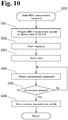
- FIG. 10 shows the flow of the WBC measurement (ordinary) in step S202.
- step S301 the controller 100 prepares a WBC measurement sample which has a dilution ratio of 52 fold. Specifically, a part (20 ⁇ L) of a sample is dispensed from the aspirating tube into the second mixing chamber MC2, and a predetermined amount (1.0 mL) of a hemolytic agent and a predetermined amount (20 ⁇ L) of a staining solution are mixed therewith to prepare a WBC measurement sample (1.0 mL) which is diluted 52 fold.
- step S302 the prepared WBC measurement sample begins to be supplied to the WBC detector D3.
- step S303 a clock is started to measure the time from when the measurement sample begins to be supplied, and in step S304 the characteristics parameters of the measurement sample are obtained by the WBC detector D3.
- step S305 the controller 100 determines whether or not 4.4 seconds has elapsed since the clock was started; the process returns to step S304 when the controller 100 determines that 4.4 seconds has not elapsed since the clock started (NO), whereas the process continues to step S306 when the controller 100 determines that 4.4 seconds has elapsed since the clock started (YES), and in step S306 the controller 100 stops supplying the WBC measurement sample to the WBC detector D3.
- the amount of the WBC sample measured in the WBC measurement is 39.8 ⁇ L.
- each measurement sample is prepared using the same amount of sample as in the previously described WBC measurement, and diluted 52 fold using the hemolytic agent and staining solution of each measurement, and the characteristic parameters of the blood cell particles within each measurement sample are obtained by the WBC detector D3 in the same process sequence as in the WBC measurement.
- step S7 The small amount measurement mode in which a small amount of sample is measured in step S7 is described below referencing FIG. 11 .
- a predetermined amount of sample (48 ⁇ L) is first aspirated through the aspirating tube by a syringe pump.
- step S401 the controller 100 prepares and measures an RBC/PLT measurement sample and an HGB measurement sample. Specifically, a part (4 ⁇ L) of a sample is dispensed from the aspirating tube into the first mixing chamber MC1, and predetermined amount (2.0 mL) of dilution liquid is mixed therewith to prepare a measurement sample (2.0 mL) which has been diluted 501 fold. Part of the prepared measurement sample (1.0 mL of the RBC/PLT measurement sample) is introduced to the RBC/PLT detector D1 (electrical resistance type sensor), and particle detection and data collection are performed for 10.5 seconds. The amount of the measured RBC/PLT measurement sample is 10.3 ⁇ L.
- the remaining measurement sample (1.0 mL) is introduced to the HGB detector D2, and a predetermined amount (0.5 mL) of hemolytic agent is mixed therewith to prepare an HGB measurement sample (1.5 mL) which has been diluted 751 fold.
- the hemoglobin concentration is measured based on the HGB measurement sample.
- step S402 the controller 100 prepares and measures a WBC measurement sample. Details of the preparation and measurement of the WBC measurement sample are described later.
- step S403 the controller 100 determines whether or not DIFF is set as a measurement item.
- the process advances to step S404 when the controller 100 determines that DIFF is set as a measurement item (YES), whereas the process moves to step S405 when the controller 100 determines that DIFF is not set as a measurement item (NO).
- step S404 the controller 100 prepares and measures a DIFF measurement sample.
- step S405 the controller 100 determines whether or not NRBC is set as a measurement item.
- the process moves to step S406 when the controller 100 determines that NRBC is set as a measurement item (YES), whereas the process advances to step S407 when the controller 100 determines that NRBC is not set as a measurement item (NO).
- step S406 the controller 100 prepares and measures an NRBC measurement sample.
- step S407 the controller 100 determines whether or not RET is set as a measurement item.
- the process continues to step S408 when the controller determines that RET is set as a measurement item (YES), whereas the process moves to step S9 when the controller 100 determines that RET is not set as a measurement item (NO).
- step S408 the controller 100 prepares and measures an RET measurement sample. Specifically, a part (5 ⁇ L) of a sample is dispensed from the aspirating tube into the fifth mixing chamber MC5, and a predetermined amount (1.0 mL) of dilution liquid and a predetermined amount (20 ⁇ L) of staining solution are mixed therewith to prepare an RET measurement sample (1.0 mL) which is diluted 205 fold.
- the diluted measurement sample (1.0 mL) is introduced to the WBC detector D3 (optical detector), and particle detection and data collection are performed for 3.2 seconds.
- the amount of the measured RET measurement sample is 2.99 ⁇ L.
- FIG. 12 shows the flow of the WBC measurement (small amount) in step S402.
- step S501 the controller 100 prepares a WBC measurement sample which has a dilution ratio of 93.7 fold. Specifically, a part (11 ⁇ L) of the sample is dispensed from the aspirating tube into the second mixing chamber MC2, and a predetermined amount (1.0 mL) of hemolytic agent and a predetermined amount (20 ⁇ L) of staining solution are mixed therewith to prepare a WBC measurement sample (1.0 mL) which has been diluted 93.7 fold.
- step S502 the prepared WBC measurement sample begins to be supplied to the WBC detector D3.
- step S503 a clock is started to measure the time from when the measurement sample begins to be supplied, and in step S504 the characteristic parameters of the measurement sample are obtained by the WBC detector D3.
- step S505 the controller 100 determines whether or not 7.9 seconds has elapsed since the clock was started; the process returns to step S504 when the controller 100 determines that 7.9 seconds has not elapsed since the clock started (NO), whereas the process continues to step S506 when the controller 100 determines that 7.9seconds has elapsed since the clock started (YES), and in step S506 the controller 100 stops supplying the WBC measurement sample to the WBC detector D3.
- the amount of the WBC sample measured in the WBC measurement is 71.4 ⁇ L.
- each measurement sample is prepared using the same amount of sample as in the previously described WBC measurement, and diluted 93.7 fold using the hemolytic agent and staining solution of each measurement, and the characteristic parameters of the blood cell particles within each measurement sample are obtained by the WBC detector D3 in the same process sequence as in the WBC measurement.
- the sample analyzer S is configured so that the measurement sample supplying speed at which the measurement sample is supplied to the detector in the small amount measurement mode is identical to the measurement sample supplying speed at which the measurement sample is supplied to the detector in the previously described ordinary measurement mode.
- the preparation of measurement sample is automated even when measuring a small amount sample. Labor is therefore eliminated and variations in the dilution ratio are avoided. Thus, measurement precision is improved.
- a lesser amount of sample (48 ⁇ L) is aspirated when the small amount measurement mode is selected compared to the amount of sample (75 ⁇ L) when the ordinary measurement mode is selected.
- the dilution ratio of the measurement sample is, for example, high (93.7 fold) in the case of the WBC measurement compared to the ordinary measurement mode (52 fold)
- the measurement time is longer (7.9 seconds) for measuring the sample than the measurement time (4.4 seconds) in the ordinary measurement mode and a larger amount of measurement sample (71.4 ⁇ L) is measured than the measurement amount (39.8 ⁇ L) in the ordinary measurement mode so that measurement precision is increased even with the higher dilution.
- the measurement sample when, for example, WBC measurement is performed when the small amount measurement mode is selected, the measurement sample is measured for a longer time than in the ordinary measurement mode, so that a larger amount of measurement sample can be measured than in the ordinary measurement mode even though the speed of the measurement sample flowing to the detector in the small amount measurement mode is identical to the speed of the measurement sample flowing to the detector in the ordinary measurement mode . Therefore, the speed at which the measurement sample is supplied to the detector can be identical for any measurement mode, and the measurement of the samples can be performed under identical conditions. Moreover, the structure of the apparatus can also be simplified.
- the amount of reagent used in the preparation of each measurement sample in the ordinary measurement mode is identical to the amount of reagent used in the preparation of each measurement sample in the small amount measurement mode.
- the structure of the apparatus can therefore be simplified.
- the measurement time need not be longer in the small amount measurement mode than in the ordinary measurement mode. In this case, the measurement of a large amount of measurement sample increases measurement precision even though the dilution ratio is high.
- the aspiration amount, dilution ratio, and measurement time of the sample in the previously described embodiment are merely simple examples and can be variously modified in accordance with the measurement sample.
- sample analyzer S and the processing device PC are separate in the present embodiment, the sample analyzer and the processing device may be integrated in a single unit.
- the sample analyzer S may be configured to perform the setting of the measurement mode in the sample analyzer S.
- a calculation process may also be performed on the measurement data obtained form the device body 2 in accordance with the difference in the dilution ratio of the measurement sample in the ordinary measurement mode and the dilution ratio of the measurement sample in the small amount measurement mode when the small amount measurement mode is set.
Priority Applications (1)
| Application Number | Priority Date | Filing Date | Title |
|---|---|---|---|
| EP23195371.2A EP4273555A3 (fr) | 2007-07-31 | 2008-07-10 | Analyseur d'échantillons, procédé d'analyse d'échantillons et produit de programme informatique |
Applications Claiming Priority (2)
| Application Number | Priority Date | Filing Date | Title |
|---|---|---|---|
| JP2007198681A JP5162177B2 (ja) | 2007-07-31 | 2007-07-31 | 粒子分析装置及び粒子分析方法 |
| EP08012498.5A EP2028495B1 (fr) | 2007-07-31 | 2008-07-10 | Analyseur d'échantillons, procédé d'analyse d'échantillons et produit de programme informatique |
Related Parent Applications (2)
| Application Number | Title | Priority Date | Filing Date |
|---|---|---|---|
| EP08012498.5A Division EP2028495B1 (fr) | 2007-07-31 | 2008-07-10 | Analyseur d'échantillons, procédé d'analyse d'échantillons et produit de programme informatique |
| EP08012498.5A Division-Into EP2028495B1 (fr) | 2007-07-31 | 2008-07-10 | Analyseur d'échantillons, procédé d'analyse d'échantillons et produit de programme informatique |
Related Child Applications (1)
| Application Number | Title | Priority Date | Filing Date |
|---|---|---|---|
| EP23195371.2A Division EP4273555A3 (fr) | 2007-07-31 | 2008-07-10 | Analyseur d'échantillons, procédé d'analyse d'échantillons et produit de programme informatique |
Publications (2)
| Publication Number | Publication Date |
|---|---|
| EP3742150A1 true EP3742150A1 (fr) | 2020-11-25 |
| EP3742150B1 EP3742150B1 (fr) | 2023-09-06 |
Family
ID=40002922
Family Applications (3)
| Application Number | Title | Priority Date | Filing Date |
|---|---|---|---|
| EP20185216.7A Active EP3742150B1 (fr) | 2007-07-31 | 2008-07-10 | Analyseur d'échantillons, procédé d'analyse d'échantillons et produit de programme informatique |
| EP08012498.5A Active EP2028495B1 (fr) | 2007-07-31 | 2008-07-10 | Analyseur d'échantillons, procédé d'analyse d'échantillons et produit de programme informatique |
| EP23195371.2A Pending EP4273555A3 (fr) | 2007-07-31 | 2008-07-10 | Analyseur d'échantillons, procédé d'analyse d'échantillons et produit de programme informatique |
Family Applications After (2)
| Application Number | Title | Priority Date | Filing Date |
|---|---|---|---|
| EP08012498.5A Active EP2028495B1 (fr) | 2007-07-31 | 2008-07-10 | Analyseur d'échantillons, procédé d'analyse d'échantillons et produit de programme informatique |
| EP23195371.2A Pending EP4273555A3 (fr) | 2007-07-31 | 2008-07-10 | Analyseur d'échantillons, procédé d'analyse d'échantillons et produit de programme informatique |
Country Status (4)
| Country | Link |
|---|---|
| US (1) | US8158439B2 (fr) |
| EP (3) | EP3742150B1 (fr) |
| JP (1) | JP5162177B2 (fr) |
| CN (1) | CN101358960B (fr) |
Families Citing this family (31)
| Publication number | Priority date | Publication date | Assignee | Title |
|---|---|---|---|---|
| EP1953527B2 (fr) | 2007-02-01 | 2024-01-03 | Sysmex Corporation | Analyseur d'échantillon et produit de programme informatique |
| JP5137436B2 (ja) * | 2007-03-29 | 2013-02-06 | シスメックス株式会社 | 試料分析装置 |
| JP4876010B2 (ja) * | 2007-03-29 | 2012-02-15 | シスメックス株式会社 | 検体分析装置および試薬吸引方法 |
| JP4948230B2 (ja) * | 2007-03-29 | 2012-06-06 | シスメックス株式会社 | 試料分析装置および試料分析方法 |
| JP4969293B2 (ja) * | 2007-03-30 | 2012-07-04 | シスメックス株式会社 | 検体分析装置 |
| US8425839B2 (en) * | 2007-03-30 | 2013-04-23 | Sysmex Corporation | Sample analyzer |
| JP4969292B2 (ja) * | 2007-03-30 | 2012-07-04 | シスメックス株式会社 | 試料分析装置 |
| EP2187219B1 (fr) * | 2007-09-03 | 2020-02-26 | Sysmex Corporation | Système d'analyse d'échantillon comprenant dispositif de préparation de réactif et dispositif de traitement d'échantillon |
| EP2037281B1 (fr) * | 2007-09-13 | 2018-10-10 | Sysmex Corporation | Analyseur d'échantillon |
| JP5431755B2 (ja) * | 2008-10-31 | 2014-03-05 | シスメックス株式会社 | 検体分析装置および検体分析方法 |
| JP5726993B2 (ja) * | 2008-10-31 | 2015-06-03 | シスメックス株式会社 | 検体分析装置および検体分析方法 |
| JP2011095182A (ja) * | 2009-10-30 | 2011-05-12 | Sysmex Corp | 細胞分析装置及び細胞分析方法 |
| CN102539300B (zh) * | 2010-12-31 | 2016-01-20 | 深圳迈瑞生物医疗电子股份有限公司 | 低值样本粒子测量方法及粒子分析仪 |
| FR2970334A1 (fr) * | 2011-01-07 | 2012-07-13 | Horiba Abx Sas | Dispositif d'inspection d'un fluide biologique |
| US10514385B2 (en) | 2011-07-22 | 2019-12-24 | Sysmex Corporation | Hematology analyzer, method, and system for quality control measurements |
| US9297819B2 (en) * | 2011-07-22 | 2016-03-29 | Sysmex Corporation | Hematology analyzing system and analyzer |
| US9317653B2 (en) * | 2011-07-22 | 2016-04-19 | Sysmex Corporation | Analyzer, and method for performing a measurement on a sample |
| JP6027742B2 (ja) * | 2011-12-28 | 2016-11-16 | シスメックス株式会社 | 血球分析装置、血球分析方法、及びコンピュータプログラム |
| JP5924950B2 (ja) | 2012-01-20 | 2016-05-25 | シスメックス株式会社 | 試料分析装置 |
| US9316661B2 (en) * | 2012-02-24 | 2016-04-19 | Perkinelmer Health Sciences, Inc. | Devices, systems and methods for loading samples |
| JP2014122851A (ja) * | 2012-12-21 | 2014-07-03 | Sysmex Corp | 免疫測定方法および免疫測定装置 |
| CN104515728B (zh) * | 2013-09-30 | 2019-07-23 | 深圳迈瑞生物医疗电子股份有限公司 | 血液细胞分析仪及网织红细胞计数装置和计数修正方法 |
| JP6580869B2 (ja) * | 2015-05-29 | 2019-09-25 | シスメックス株式会社 | 検体分析装置、搬送装置、及び方法 |
| CN106706943A (zh) * | 2015-07-27 | 2017-05-24 | 博奥赛斯(天津)生物科技有限公司 | 一种荧光免疫分析仪进样检测机构 |
| CN106290817B (zh) * | 2016-08-27 | 2018-01-16 | 青岛市妇女儿童医院 | 一种医疗检测试样免疫分析系统以及分析方法 |
| WO2019000324A1 (fr) * | 2017-06-29 | 2019-01-03 | 深圳迈瑞生物医疗电子股份有限公司 | Procédé et dispositif de détection de sang |
| BR102018075954A2 (pt) * | 2017-09-15 | 2019-11-12 | Horiba Ltd | aparelho de análise de partículas |
| JP6800287B2 (ja) * | 2019-07-10 | 2020-12-16 | 株式会社日立ハイテク | 自動分析装置及び試料希釈攪拌方法 |
| CN111893032A (zh) * | 2019-12-12 | 2020-11-06 | 山东鑫科生物科技股份有限公司 | 具有空中清洗机构的细菌计数装置 |
| CN113522171B (zh) * | 2021-07-21 | 2024-03-19 | 高砂电气(苏州)有限公司 | 一种定量排出装置 |
| WO2023122238A1 (fr) * | 2021-12-22 | 2023-06-29 | Beckman Coulter, Inc. | Transfert de fluide dans un système d'analyse biologique |
Citations (9)
| Publication number | Priority date | Publication date | Assignee | Title |
|---|---|---|---|---|
| US5298424A (en) * | 1991-03-26 | 1994-03-29 | Kabushiki Kaisha Toshiba | Automatic chemical analysis system and automatic chemical analysis method |
| US5679575A (en) * | 1994-12-21 | 1997-10-21 | Toa Medical Electronics, Co., Ltd. | Particle measuring apparatus and method |
| US5690895A (en) * | 1993-01-26 | 1997-11-25 | Hitachi, Ltd. | Flow cell apparatus |
| JPH11183472A (ja) | 1997-12-22 | 1999-07-09 | Sysmex Corp | 血液分析装置 |
| EP1033573A2 (fr) * | 1999-02-26 | 2000-09-06 | Sysmex Corporation | Procédé et système de détection automatique |
| US6322752B1 (en) * | 1999-09-08 | 2001-11-27 | Coulter International Corp. | Method and apparatus for aspirating and dispensing liquids |
| US20050074361A1 (en) * | 2001-09-06 | 2005-04-07 | Sysmex Corporation | Automatic sample analyzer and its components |
| US6972424B1 (en) * | 2002-04-16 | 2005-12-06 | Pointsource Technologies, Llc | High detection rate particle identifier |
| US20060153737A1 (en) * | 2004-12-15 | 2006-07-13 | Yoshiaki Saito | Automatic blood chemistry analyzer |
Family Cites Families (58)
| Publication number | Priority date | Publication date | Assignee | Title |
|---|---|---|---|---|
| US3523733A (en) * | 1966-01-05 | 1970-08-11 | Technicon Corp | Method and apparatus for particle counting |
| US3567390A (en) * | 1968-04-03 | 1971-03-02 | Coulter Electronics | Fluid transfer valve structure and diluting system |
| US3578039A (en) * | 1968-10-15 | 1971-05-11 | Baxter Laboratories Inc | Automatic proportioner assembly |
| US3858450A (en) * | 1971-10-21 | 1975-01-07 | Coulter Electronics | Sample mixing and metering apparatus |
| US3976429A (en) * | 1973-10-16 | 1976-08-24 | Coulter Electronics, Inc. | Backwash system for diluting apparatus |
| US3963148A (en) * | 1974-01-10 | 1976-06-15 | Coulter Electronics, Inc. | Apparatus for drawing, measuring and discharging proportional amounts of fluid |
| US4052596A (en) * | 1974-12-23 | 1977-10-04 | Hycel, Inc. | Automatic hematology analyzer |
| JPS5916667B2 (ja) * | 1975-02-28 | 1984-04-17 | トウアイヨウデンシ カブシキガイシヤ | 自動血液分析装置 |
| US3991055A (en) * | 1975-05-30 | 1976-11-09 | Coulter Electronics, Inc. | Liquid transfer valve |
| US4068169A (en) * | 1976-09-21 | 1978-01-10 | Hycel, Inc. | Method and apparatus for determining hematocrit |
| US4099917A (en) * | 1977-07-21 | 1978-07-11 | Technicon Instruments Corporation | Process for preparing a cell suspension from blood for discrimination of white blood cells and platelets from other blood particles |
| US4157499A (en) * | 1977-09-15 | 1979-06-05 | Becton, Dickinson And Company | Blood cell counter having dual testing heads |
| US4152391A (en) * | 1977-12-16 | 1979-05-01 | Coulter Electronics, Inc. | Liquid transfer valve |
| CH610666A5 (fr) * | 1978-03-14 | 1979-04-30 | Contraves Ag | |
| US4220621A (en) * | 1979-02-23 | 1980-09-02 | Coulter Electronics, Inc. | Backwash system for diluting apparatus |
| US4333356A (en) * | 1979-04-27 | 1982-06-08 | Ciba-Geigy Corporation | Mixing apparatus |
| US4387076A (en) * | 1981-10-14 | 1983-06-07 | Coulter Electronics, Inc. | Sample feeding arrangement |
| JPS58105065A (ja) * | 1981-12-17 | 1983-06-22 | Olympus Optical Co Ltd | 免疫学的凝集反応に基く分析装置 |
| US4683212A (en) * | 1982-09-30 | 1987-07-28 | Technicon Instruments Corporation | Random access single channel sheath stream apparatus |
| US4606631A (en) * | 1983-05-12 | 1986-08-19 | Kabushiki Kaisha Toshiba | Particle counter |
| US4729876A (en) * | 1984-11-27 | 1988-03-08 | Nova Celltrak, Inc. | Blood analysis system |
| US4726237A (en) * | 1985-06-19 | 1988-02-23 | Sequoia-Turner Corporation | Fluid metering apparatus and method |
| US4706207A (en) * | 1985-06-24 | 1987-11-10 | Nova Celltrak, Inc. | Count accuracy control means for a blood analyses system |
| JPH0635972B2 (ja) * | 1986-11-27 | 1994-05-11 | 東亜医用電子株式会社 | フロ−サイトメトリ−による白血球の分類方法 |
| US4957008A (en) * | 1988-12-28 | 1990-09-18 | Coulter Electronics, Inc. | Fluid sampling and transfer valve assembly |
| US4948565A (en) * | 1989-04-25 | 1990-08-14 | Fisher Scientific Company | Analytical system |
| US5089234A (en) * | 1989-08-09 | 1992-02-18 | Serono-Baker Diagnostics, Inc. | Controlled environment liquid diluting and transfer valve assembly |
| DK111990D0 (da) * | 1990-05-04 | 1990-05-04 | Biometic Aps | Apparat og fremgangsmaade til analyse af en vaeskesuspension |
| JP2573091B2 (ja) * | 1990-09-23 | 1997-01-16 | 株式会社堀場製作所 | 液体測定装置 |
| JP2972367B2 (ja) * | 1991-03-20 | 1999-11-08 | 株式会社日立製作所 | 細胞分析装置 |
| JPH07119757B2 (ja) * | 1991-03-31 | 1995-12-20 | 日本光電工業株式会社 | 血球計数装置 |
| US5254313A (en) * | 1991-04-24 | 1993-10-19 | Toa Medical Electronics Co., Ltd. | Apparatus for diluting and mixing a liquid specimen |
| JP3014818B2 (ja) * | 1991-04-24 | 2000-02-28 | シスメックス株式会社 | 試料希釈混合方法及び装置 |
| JP3077772B2 (ja) * | 1991-06-05 | 2000-08-14 | シスメックス株式会社 | 複数の分析モジュールを用いる粒子自動分析方法及び装置 |
| JP3130608B2 (ja) * | 1991-11-20 | 2001-01-31 | シスメックス株式会社 | サンプリングバルブ |
| US5380491A (en) * | 1993-01-21 | 1995-01-10 | Cdc Technologies, Inc. | Apparatus for pumping and directing fluids for hematology testing |
| US6812032B1 (en) * | 1993-01-21 | 2004-11-02 | Cdc Technologies, Inc. | Apparatus and method for making a plurality of reagent mixtures and analyzing particle distributions of the reagent mixtures |
| US5728351A (en) * | 1993-01-21 | 1998-03-17 | Cdc Technologies, Inc. | Apparatus for making a plurality of reagent mixtures and analyzing particle distributions of the reagent mixtures |
| DE4303688C3 (de) * | 1993-02-09 | 2000-06-15 | Heraeus Electro Nite Int | Probennehmer für Metallschmelze |
| US5512248A (en) * | 1993-11-23 | 1996-04-30 | Van; Jack F. J. | Twin-probe blood sample diluting device |
| SE513881C2 (sv) * | 1994-01-10 | 2000-11-20 | Boule Medical Ab | Förfarande och anordning för analys av vätskeprover |
| GB9405028D0 (en) * | 1994-03-15 | 1994-04-27 | Counting Tech Ltd | Fluid diluter |
| US5631165A (en) * | 1994-08-01 | 1997-05-20 | Abbott Laboratories | Method for performing automated hematology and cytometry analysis |
| JP3572792B2 (ja) * | 1996-04-04 | 2004-10-06 | 東ソー株式会社 | 前処理装置 |
| SE507956C2 (sv) * | 1996-11-20 | 1998-08-03 | Medonic Ab | Utspädnings- och mätanordning för partikelräkning |
| EP0905514B1 (fr) * | 1997-09-27 | 2003-11-26 | Horiba, Ltd. | Appareil de dénombrement de cellules sanguines et d'essais immunologiques utilisant tout le sang |
| FR2771175B1 (fr) * | 1997-11-19 | 2000-02-18 | Francois Melet | Dispositif automatique compteur analyseur d'hematologie |
| US6228652B1 (en) * | 1999-02-16 | 2001-05-08 | Coulter International Corp. | Method and apparatus for analyzing cells in a whole blood sample |
| DE60139056D1 (de) * | 2000-09-18 | 2009-08-06 | Sysmex Corp | Blutzellen-Detektor, Blutanalysegerät und Blutanalyseverfahren unter Verwendung des Detektors |
| US7220383B2 (en) * | 2001-07-13 | 2007-05-22 | Metara, Inc. | Method and instrument for automated analysis of fluid-based processing systems |
| SE521252C2 (sv) * | 2001-11-21 | 2003-10-14 | Boule Medical Ab | Engångsapparat för användning vid blodprov och instrument för användning med apparaten |
| US6662826B1 (en) * | 2002-10-07 | 2003-12-16 | Abbott Laboratories | Liquid metering and transfer valve assembly with port switch |
| US7427376B2 (en) * | 2002-11-18 | 2008-09-23 | Sysmex Corporation | Sample analyzer and its components |
| WO2005040784A1 (fr) * | 2003-10-29 | 2005-05-06 | Arkray, Inc. | Procede et dispositif d'analyse d'echantillons |
| JP4393886B2 (ja) * | 2004-02-17 | 2010-01-06 | 株式会社日立ハイテクマニファクチャ&サービス | 原子吸光光度計 |
| US9243993B2 (en) * | 2005-03-17 | 2016-01-26 | Sysmex Corporation | Sample analyzer and sample analyzing method |
| JP4873969B2 (ja) * | 2005-03-17 | 2012-02-08 | シスメックス株式会社 | 試料分析装置及び試料分析方法 |
| US7661326B2 (en) * | 2006-10-26 | 2010-02-16 | Beckman Coulter, Inc. | Apparatus for aspirating and dispensing liquids in an automated analyzer |
-
2007
- 2007-07-31 JP JP2007198681A patent/JP5162177B2/ja active Active
-
2008
- 2008-07-10 EP EP20185216.7A patent/EP3742150B1/fr active Active
- 2008-07-10 EP EP08012498.5A patent/EP2028495B1/fr active Active
- 2008-07-10 EP EP23195371.2A patent/EP4273555A3/fr active Pending
- 2008-07-16 US US12/218,607 patent/US8158439B2/en active Active
- 2008-07-23 CN CN2008101344307A patent/CN101358960B/zh active Active
Patent Citations (9)
| Publication number | Priority date | Publication date | Assignee | Title |
|---|---|---|---|---|
| US5298424A (en) * | 1991-03-26 | 1994-03-29 | Kabushiki Kaisha Toshiba | Automatic chemical analysis system and automatic chemical analysis method |
| US5690895A (en) * | 1993-01-26 | 1997-11-25 | Hitachi, Ltd. | Flow cell apparatus |
| US5679575A (en) * | 1994-12-21 | 1997-10-21 | Toa Medical Electronics, Co., Ltd. | Particle measuring apparatus and method |
| JPH11183472A (ja) | 1997-12-22 | 1999-07-09 | Sysmex Corp | 血液分析装置 |
| EP1033573A2 (fr) * | 1999-02-26 | 2000-09-06 | Sysmex Corporation | Procédé et système de détection automatique |
| US6322752B1 (en) * | 1999-09-08 | 2001-11-27 | Coulter International Corp. | Method and apparatus for aspirating and dispensing liquids |
| US20050074361A1 (en) * | 2001-09-06 | 2005-04-07 | Sysmex Corporation | Automatic sample analyzer and its components |
| US6972424B1 (en) * | 2002-04-16 | 2005-12-06 | Pointsource Technologies, Llc | High detection rate particle identifier |
| US20060153737A1 (en) * | 2004-12-15 | 2006-07-13 | Yoshiaki Saito | Automatic blood chemistry analyzer |
Also Published As
| Publication number | Publication date |
|---|---|
| CN101358960B (zh) | 2013-04-24 |
| US8158439B2 (en) | 2012-04-17 |
| EP2028495A3 (fr) | 2015-03-25 |
| EP2028495A2 (fr) | 2009-02-25 |
| EP2028495B1 (fr) | 2020-08-19 |
| CN101358960A (zh) | 2009-02-04 |
| EP3742150B1 (fr) | 2023-09-06 |
| EP4273555A3 (fr) | 2024-01-10 |
| EP4273555A2 (fr) | 2023-11-08 |
| US20090035873A1 (en) | 2009-02-05 |
| JP2009036530A (ja) | 2009-02-19 |
| JP5162177B2 (ja) | 2013-03-13 |
Similar Documents
| Publication | Publication Date | Title |
|---|---|---|
| EP3742150B1 (fr) | Analyseur d'échantillons, procédé d'analyse d'échantillons et produit de programme informatique | |
| US11415575B2 (en) | Sample analyzer and computer program product | |
| JP5732576B2 (ja) | 血液分析装置および測定試料調製方法 | |
| EP3260842B1 (fr) | Analyseur hématologique et procédé d'analyse d'une échantillon | |
| US8808623B2 (en) | Diagnosis assisting system, diagnosis assisting information providing device and computer program product | |
| EP1975625B1 (fr) | Analyseur d'échantillons, procédé d'analyse d'échantillons et produit de programme informatique | |
| US9322834B2 (en) | Sample analyzer, blood analyzer and displaying method | |
| JP4873969B2 (ja) | 試料分析装置及び試料分析方法 | |
| JP4825562B2 (ja) | 試料測定装置及び試料測定方法 |
Legal Events
| Date | Code | Title | Description |
|---|---|---|---|
| PUAI | Public reference made under article 153(3) epc to a published international application that has entered the european phase |
Free format text: ORIGINAL CODE: 0009012 |
|
| STAA | Information on the status of an ep patent application or granted ep patent |
Free format text: STATUS: THE APPLICATION HAS BEEN PUBLISHED |
|
| AC | Divisional application: reference to earlier application |
Ref document number: 2028495 Country of ref document: EP Kind code of ref document: P |
|
| AK | Designated contracting states |
Kind code of ref document: A1 Designated state(s): AT BE BG CH CY CZ DE DK EE ES FI FR GB GR HR HU IE IS IT LI LT LU LV MC MT NL NO PL PT RO SE SI SK TR |
|
| STAA | Information on the status of an ep patent application or granted ep patent |
Free format text: STATUS: REQUEST FOR EXAMINATION WAS MADE |
|
| 17P | Request for examination filed |
Effective date: 20210512 |
|
| RBV | Designated contracting states (corrected) |
Designated state(s): AT BE BG CH CY CZ DE DK EE ES FI FR GB GR HR HU IE IS IT LI LT LU LV MC MT NL NO PL PT RO SE SI SK TR |
|
| GRAP | Despatch of communication of intention to grant a patent |
Free format text: ORIGINAL CODE: EPIDOSNIGR1 |
|
| STAA | Information on the status of an ep patent application or granted ep patent |
Free format text: STATUS: GRANT OF PATENT IS INTENDED |
|
| INTG | Intention to grant announced |
Effective date: 20221025 |
|
| GRAJ | Information related to disapproval of communication of intention to grant by the applicant or resumption of examination proceedings by the epo deleted |
Free format text: ORIGINAL CODE: EPIDOSDIGR1 |
|
| STAA | Information on the status of an ep patent application or granted ep patent |
Free format text: STATUS: REQUEST FOR EXAMINATION WAS MADE |
|
| GRAP | Despatch of communication of intention to grant a patent |
Free format text: ORIGINAL CODE: EPIDOSNIGR1 |
|
| STAA | Information on the status of an ep patent application or granted ep patent |
Free format text: STATUS: GRANT OF PATENT IS INTENDED |
|
| INTC | Intention to grant announced (deleted) | ||
| INTG | Intention to grant announced |
Effective date: 20230320 |
|
| GRAS | Grant fee paid |
Free format text: ORIGINAL CODE: EPIDOSNIGR3 |
|
| GRAA | (expected) grant |
Free format text: ORIGINAL CODE: 0009210 |
|
| STAA | Information on the status of an ep patent application or granted ep patent |
Free format text: STATUS: THE PATENT HAS BEEN GRANTED |
|
| AC | Divisional application: reference to earlier application |
Ref document number: 2028495 Country of ref document: EP Kind code of ref document: P |
|
| AK | Designated contracting states |
Kind code of ref document: B1 Designated state(s): AT BE BG CH CY CZ DE DK EE ES FI FR GB GR HR HU IE IS IT LI LT LU LV MC MT NL NO PL PT RO SE SI SK TR |
|
| REG | Reference to a national code |
Ref country code: GB Ref legal event code: FG4D |
|
| REG | Reference to a national code |
Ref country code: CH Ref legal event code: EP |
|
| REG | Reference to a national code |
Ref country code: DE Ref legal event code: R096 Ref document number: 602008064861 Country of ref document: DE |
|
| REG | Reference to a national code |
Ref country code: IE Ref legal event code: FG4D |
|
| REG | Reference to a national code |
Ref country code: LT Ref legal event code: MG9D |
|
| REG | Reference to a national code |
Ref country code: NL Ref legal event code: MP Effective date: 20230906 |
|
| PG25 | Lapsed in a contracting state [announced via postgrant information from national office to epo] |
Ref country code: GR Free format text: LAPSE BECAUSE OF FAILURE TO SUBMIT A TRANSLATION OF THE DESCRIPTION OR TO PAY THE FEE WITHIN THE PRESCRIBED TIME-LIMIT Effective date: 20231207 |
|
| PG25 | Lapsed in a contracting state [announced via postgrant information from national office to epo] |
Ref country code: SE Free format text: LAPSE BECAUSE OF FAILURE TO SUBMIT A TRANSLATION OF THE DESCRIPTION OR TO PAY THE FEE WITHIN THE PRESCRIBED TIME-LIMIT Effective date: 20230906 Ref country code: NO Free format text: LAPSE BECAUSE OF FAILURE TO SUBMIT A TRANSLATION OF THE DESCRIPTION OR TO PAY THE FEE WITHIN THE PRESCRIBED TIME-LIMIT Effective date: 20231206 Ref country code: LV Free format text: LAPSE BECAUSE OF FAILURE TO SUBMIT A TRANSLATION OF THE DESCRIPTION OR TO PAY THE FEE WITHIN THE PRESCRIBED TIME-LIMIT Effective date: 20230906 Ref country code: LT Free format text: LAPSE BECAUSE OF FAILURE TO SUBMIT A TRANSLATION OF THE DESCRIPTION OR TO PAY THE FEE WITHIN THE PRESCRIBED TIME-LIMIT Effective date: 20230906 Ref country code: HR Free format text: LAPSE BECAUSE OF FAILURE TO SUBMIT A TRANSLATION OF THE DESCRIPTION OR TO PAY THE FEE WITHIN THE PRESCRIBED TIME-LIMIT Effective date: 20230906 Ref country code: GR Free format text: LAPSE BECAUSE OF FAILURE TO SUBMIT A TRANSLATION OF THE DESCRIPTION OR TO PAY THE FEE WITHIN THE PRESCRIBED TIME-LIMIT Effective date: 20231207 Ref country code: FI Free format text: LAPSE BECAUSE OF FAILURE TO SUBMIT A TRANSLATION OF THE DESCRIPTION OR TO PAY THE FEE WITHIN THE PRESCRIBED TIME-LIMIT Effective date: 20230906 |
|
| REG | Reference to a national code |
Ref country code: AT Ref legal event code: MK05 Ref document number: 1609136 Country of ref document: AT Kind code of ref document: T Effective date: 20230906 |
|
| PG25 | Lapsed in a contracting state [announced via postgrant information from national office to epo] |
Ref country code: NL Free format text: LAPSE BECAUSE OF FAILURE TO SUBMIT A TRANSLATION OF THE DESCRIPTION OR TO PAY THE FEE WITHIN THE PRESCRIBED TIME-LIMIT Effective date: 20230906 |
|
| PG25 | Lapsed in a contracting state [announced via postgrant information from national office to epo] |
Ref country code: IS Free format text: LAPSE BECAUSE OF FAILURE TO SUBMIT A TRANSLATION OF THE DESCRIPTION OR TO PAY THE FEE WITHIN THE PRESCRIBED TIME-LIMIT Effective date: 20240106 |