EP3741944A1 - Gelenkband - Google Patents
Gelenkband Download PDFInfo
- Publication number
- EP3741944A1 EP3741944A1 EP20175855.4A EP20175855A EP3741944A1 EP 3741944 A1 EP3741944 A1 EP 3741944A1 EP 20175855 A EP20175855 A EP 20175855A EP 3741944 A1 EP3741944 A1 EP 3741944A1
- Authority
- EP
- European Patent Office
- Prior art keywords
- hinge
- clamping
- axis element
- latching
- hinge axis
- Prior art date
- Legal status (The legal status is an assumption and is not a legal conclusion. Google has not performed a legal analysis and makes no representation as to the accuracy of the status listed.)
- Granted
Links
- 230000006835 compression Effects 0.000 description 3
- 238000007906 compression Methods 0.000 description 3
- 230000000712 assembly Effects 0.000 description 2
- 238000000429 assembly Methods 0.000 description 2
- 230000015572 biosynthetic process Effects 0.000 description 2
- 230000010355 oscillation Effects 0.000 description 2
- 239000011521 glass Substances 0.000 description 1
- 239000002655 kraft paper Substances 0.000 description 1
- 210000003041 ligament Anatomy 0.000 description 1
- 210000000707 wrist Anatomy 0.000 description 1
Images


Classifications
-
- E—FIXED CONSTRUCTIONS
- E05—LOCKS; KEYS; WINDOW OR DOOR FITTINGS; SAFES
- E05D—HINGES OR SUSPENSION DEVICES FOR DOORS, WINDOWS OR WINGS
- E05D5/00—Construction of single parts, e.g. the parts for attachment
- E05D5/02—Parts for attachment, e.g. flaps
- E05D5/0246—Parts for attachment, e.g. flaps for attachment to glass panels
-
- E—FIXED CONSTRUCTIONS
- E05—LOCKS; KEYS; WINDOW OR DOOR FITTINGS; SAFES
- E05D—HINGES OR SUSPENSION DEVICES FOR DOORS, WINDOWS OR WINGS
- E05D5/00—Construction of single parts, e.g. the parts for attachment
- E05D5/02—Parts for attachment, e.g. flaps
- E05D5/04—Flat flaps
-
- E—FIXED CONSTRUCTIONS
- E05—LOCKS; KEYS; WINDOW OR DOOR FITTINGS; SAFES
- E05D—HINGES OR SUSPENSION DEVICES FOR DOORS, WINDOWS OR WINGS
- E05D3/00—Hinges with pins
- E05D3/02—Hinges with pins with one pin
-
- E—FIXED CONSTRUCTIONS
- E05—LOCKS; KEYS; WINDOW OR DOOR FITTINGS; SAFES
- E05D—HINGES OR SUSPENSION DEVICES FOR DOORS, WINDOWS OR WINGS
- E05D11/00—Additional features or accessories of hinges
- E05D11/10—Devices for preventing movement between relatively-movable hinge parts
- E05D11/1007—Devices for preventing movement between relatively-movable hinge parts with positive locking
-
- E—FIXED CONSTRUCTIONS
- E05—LOCKS; KEYS; WINDOW OR DOOR FITTINGS; SAFES
- E05D—HINGES OR SUSPENSION DEVICES FOR DOORS, WINDOWS OR WINGS
- E05D11/00—Additional features or accessories of hinges
- E05D11/10—Devices for preventing movement between relatively-movable hinge parts
- E05D11/1014—Devices for preventing movement between relatively-movable hinge parts for maintaining the hinge in only one position, e.g. closed
-
- E—FIXED CONSTRUCTIONS
- E05—LOCKS; KEYS; WINDOW OR DOOR FITTINGS; SAFES
- E05D—HINGES OR SUSPENSION DEVICES FOR DOORS, WINDOWS OR WINGS
- E05D11/00—Additional features or accessories of hinges
- E05D11/10—Devices for preventing movement between relatively-movable hinge parts
- E05D11/1028—Devices for preventing movement between relatively-movable hinge parts for maintaining the hinge in two or more positions, e.g. intermediate or fully open
- E05D11/105—Devices for preventing movement between relatively-movable hinge parts for maintaining the hinge in two or more positions, e.g. intermediate or fully open the maintaining means acting perpendicularly to the pivot axis
- E05D11/1064—Devices for preventing movement between relatively-movable hinge parts for maintaining the hinge in two or more positions, e.g. intermediate or fully open the maintaining means acting perpendicularly to the pivot axis with a coil spring perpendicular to the pivot axis
-
- E—FIXED CONSTRUCTIONS
- E05—LOCKS; KEYS; WINDOW OR DOOR FITTINGS; SAFES
- E05D—HINGES OR SUSPENSION DEVICES FOR DOORS, WINDOWS OR WINGS
- E05D5/00—Construction of single parts, e.g. the parts for attachment
- E05D5/10—Pins, sockets or sleeves; Removable pins
-
- E—FIXED CONSTRUCTIONS
- E05—LOCKS; KEYS; WINDOW OR DOOR FITTINGS; SAFES
- E05D—HINGES OR SUSPENSION DEVICES FOR DOORS, WINDOWS OR WINGS
- E05D15/00—Suspension arrangements for wings
- E05D15/48—Suspension arrangements for wings allowing alternative movements
- E05D15/54—Suspension arrangements for wings allowing alternative movements for opening both inwards and outwards
-
- E—FIXED CONSTRUCTIONS
- E05—LOCKS; KEYS; WINDOW OR DOOR FITTINGS; SAFES
- E05D—HINGES OR SUSPENSION DEVICES FOR DOORS, WINDOWS OR WINGS
- E05D5/00—Construction of single parts, e.g. the parts for attachment
- E05D5/10—Pins, sockets or sleeves; Removable pins
- E05D2005/102—Pins
-
- E—FIXED CONSTRUCTIONS
- E05—LOCKS; KEYS; WINDOW OR DOOR FITTINGS; SAFES
- E05D—HINGES OR SUSPENSION DEVICES FOR DOORS, WINDOWS OR WINGS
- E05D11/00—Additional features or accessories of hinges
- E05D11/10—Devices for preventing movement between relatively-movable hinge parts
- E05D2011/1092—Devices for preventing movement between relatively-movable hinge parts the angle between the hinge parts being adjustable
-
- E—FIXED CONSTRUCTIONS
- E05—LOCKS; KEYS; WINDOW OR DOOR FITTINGS; SAFES
- E05Y—INDEXING SCHEME RELATING TO HINGES OR OTHER SUSPENSION DEVICES FOR DOORS, WINDOWS OR WINGS AND DEVICES FOR MOVING WINGS INTO OPEN OR CLOSED POSITION, CHECKS FOR WINGS AND WING FITTINGS NOT OTHERWISE PROVIDED FOR, CONCERNED WITH THE FUNCTIONING OF THE WING
- E05Y2600/00—Mounting or coupling arrangements for elements provided for in this subclass
- E05Y2600/10—Adjustable or movable
- E05Y2600/30—Adjustable or movable characterised by the type of motion
- E05Y2600/32—Rotary motion
- E05Y2600/324—Rotary motion around a vertical axis
-
- E—FIXED CONSTRUCTIONS
- E05—LOCKS; KEYS; WINDOW OR DOOR FITTINGS; SAFES
- E05Y—INDEXING SCHEME RELATING TO HINGES OR OTHER SUSPENSION DEVICES FOR DOORS, WINDOWS OR WINGS AND DEVICES FOR MOVING WINGS INTO OPEN OR CLOSED POSITION, CHECKS FOR WINGS AND WING FITTINGS NOT OTHERWISE PROVIDED FOR, CONCERNED WITH THE FUNCTIONING OF THE WING
- E05Y2800/00—Details, accessories and auxiliary operations not otherwise provided for
- E05Y2800/20—Combinations of elements
- E05Y2800/21—Combinations of elements of identical elements, e.g. of identical compression springs
-
- E—FIXED CONSTRUCTIONS
- E05—LOCKS; KEYS; WINDOW OR DOOR FITTINGS; SAFES
- E05Y—INDEXING SCHEME RELATING TO HINGES OR OTHER SUSPENSION DEVICES FOR DOORS, WINDOWS OR WINGS AND DEVICES FOR MOVING WINGS INTO OPEN OR CLOSED POSITION, CHECKS FOR WINGS AND WING FITTINGS NOT OTHERWISE PROVIDED FOR, CONCERNED WITH THE FUNCTIONING OF THE WING
- E05Y2900/00—Application of doors, windows, wings or fittings thereof
- E05Y2900/10—Application of doors, windows, wings or fittings thereof for buildings or parts thereof
- E05Y2900/114—Application of doors, windows, wings or fittings thereof for buildings or parts thereof for showers
-
- E—FIXED CONSTRUCTIONS
- E05—LOCKS; KEYS; WINDOW OR DOOR FITTINGS; SAFES
- E05Y—INDEXING SCHEME RELATING TO HINGES OR OTHER SUSPENSION DEVICES FOR DOORS, WINDOWS OR WINGS AND DEVICES FOR MOVING WINGS INTO OPEN OR CLOSED POSITION, CHECKS FOR WINGS AND WING FITTINGS NOT OTHERWISE PROVIDED FOR, CONCERNED WITH THE FUNCTIONING OF THE WING
- E05Y2900/00—Application of doors, windows, wings or fittings thereof
- E05Y2900/10—Application of doors, windows, wings or fittings thereof for buildings or parts thereof
- E05Y2900/13—Application of doors, windows, wings or fittings thereof for buildings or parts thereof characterised by the type of wing
- E05Y2900/132—Doors
-
- E—FIXED CONSTRUCTIONS
- E05—LOCKS; KEYS; WINDOW OR DOOR FITTINGS; SAFES
- E05Y—INDEXING SCHEME RELATING TO HINGES OR OTHER SUSPENSION DEVICES FOR DOORS, WINDOWS OR WINGS AND DEVICES FOR MOVING WINGS INTO OPEN OR CLOSED POSITION, CHECKS FOR WINGS AND WING FITTINGS NOT OTHERWISE PROVIDED FOR, CONCERNED WITH THE FUNCTIONING OF THE WING
- E05Y2900/00—Application of doors, windows, wings or fittings thereof
- E05Y2900/10—Application of doors, windows, wings or fittings thereof for buildings or parts thereof
- E05Y2900/13—Application of doors, windows, wings or fittings thereof for buildings or parts thereof characterised by the type of wing
- E05Y2900/148—Windows
Definitions
- the invention relates to a hinge, in particular for a swing door, with (i) at least one hinge axis element, (ii) a first hinge part and a second hinge part, which are connected to one another in a hinge-like manner via the at least one hinge axis element, (iii) at least one latching arrangement which at least a latching device arranged on the second hinge part with a latching body and at least one latching recess arranged on the hinge axis element, the latching device being set up such that the latching body engages in the latching recess in a latching position and (iv) a tensioning means for releasably fixing the hinge axis element on the first Hinge part in which an angular position of the hinge axis element and the latching recess can be set with respect to the first hinge part.
- the angular position of the two hinge parts when the latching body is locked into the latching recess marks a zero point with respect to a swing of the hinge parts against one another or a corresponding door or a corresponding window.
- This zero point of oscillation can be shifted by turning the two parts of the belt against each other when the clamping device is released.
- the rotation generally takes place when the locking body is locked into the locking recess.
- the angular position of the hinge axis element with respect to the second hinge part is well defined.
- the document DE 10 2011 088 192 A1 describes a hinge for a swing door, with (i) at least one hinge axis element, (ii) a first hinge part and a second hinge part, which are connected to one another in a hinge-like manner via the at least one hinge axis element, (iii) at least one latching arrangement, which is at least one on the second
- a latching device arranged on the hinge part comprises a latching body and at least one latching recess arranged on the hinge axis element, the latching device being set up such that the latching body engages in the latching recess in a latching position and (iv) a clamping means for releasably fixing the hinge axis element on the first hinge part, in which an angular position of the hinge axis element and the latching recess is adjustable with respect to the first hinge part.
- the clamping means has a locking screw held in / on the bearing element and designed as a threaded pin with a conical tip as a clamping element, which presses on one side of a flank of this tip onto a conical end section of this hinge axis element to fix the selected angular position of the hinge axis element.
- the force that occurs during tensioning / clamping only acts on a very small line-like area, so that a correspondingly high pressure prevails.
- the one-sided loading can lead to the hinge axis element becoming misaligned / tilting, so that the force is distributed unevenly over the already small area, so that a very high pressure can arise locally.
- the clamping surfaces of each pair of clamping jaws jointly overlap the circumference of the hinge axis element in a corresponding axis section by at least 33%, preferably at least 50%.
- 50% these are two opposing circumferential arcs of 90 ° each, i.e. 180 ° together.
- the clamping marks that arise with these dimensions are usually hardly detectable.
- the clamping means has a fixed clamping state with a well-defined clamping force of the clamping jaws with respect to the hinge axis element.
- the clamping device can optionally be brought into this state and also held in this state.
- the clamping force can be chosen so that a clamping mark in a hinge with such a tensioning means could lead to a reduced clamping force, but not to a "sliding into” the old clamping mark.
- the clamping means has two clamping means parts, each part of which comprises one clamping jaw per pair of clamping jaws.
- the clamping means has at least one device for fixing a relative position of the clamping means parts with one another, in particular in the form of a screw connection, in which the clamping jaws are clamped in the angular position of the hinge axis element fixing clamp position. This is then the aforementioned "fixed clamping state”.
- each of the two clamping means parts that can be moved relative to one another has a base and at least one arm on which the clamping jaw for the corresponding pair of clamping jaws is arranged at a distance from the base.
- the screw connection is not used here directly for clamping / clamping, but rather to determine the relative position of the clamping device parts by fastening the clamping device parts to one another.
- the device for establishing a relative position of the clamping means parts with one another engages in each case on the base of the clamping means parts involved. If this device is a screw connection, it is preferably a central screw connection, in particular by means of only one screw.
- the clamping means parts comprise the base and two arms which are arranged in a U-shape. Via this U-shape, the two clamping means parts which can be moved relative to one another can, for example, fix a single joint axis element in a clamping manner at both of its ends.
- the contour of the at least one hinge axis element is circular-cylindrical, the clamping surfaces of the clamping jaws being adapted accordingly.
- each of the clamping jaws forms, for example, a type of half-shell in relation to its respective clamping surface.
- the latching device has a device for applying force to the latching body.
- the Device for applying force to the latching body comprises a spring device, in particular a compression spring. Such a spring loading has proven itself in practice.
- the Fig. 1 shows the assemblies of a hinge 10, more precisely a hinge for a swing door (not shown), in particular a glass swing door.
- the first assembly has a first band part 12 and a tensioning means 14.
- the second assembly has a second hinge part 16 and a bearing unit 18 which is fastened to the second hinge part 16 and in which a pin-like hinge axis element 20 is rotatably mounted via a bearing bush 22.
- the hinge axis element 20 protrudes with its end sections 24, 26 on opposite sides of the bearing unit 18.
- Locking arrangement 28 shown, via which a zero point of the pendulum movement of the swing door is defined.
- the clamping device 14 has two separable clamping device parts 30, 32, of which the first clamping device part 30 is attached to the first hinge part 12, while the second clamping device part 32 can be detachably attached to the first clamping device part 30 via a screw connection 34 .
- the screw connection 34 forms, together with projection-recess arrangements, a device for fixing a relative position of the clamping means parts with one another.
- the first hinge part 12 is a hinge part for a door leaf of the swing door and the second hinge part 16 is a hinge part for attachment to a door frame, a wall or another fixed element.
- the second hinge part 16 is the hinge part for the door leaf of the swing door and the first hinge part 12 to be a hinge part for attachment to a corresponding stationary element.
- the two hinge parts 12, 16 are connected to one another in a hinge-like manner within the mounted hinge hinge 10 via the hinge axis element 20.
- a detent position of the detent arrangement 28 results in a zero point of the pendulum movement of the swing door.
- the hinge axis element 20 can be releasably fixed on the first hinge part 12 via the tensioning means 14 so that a desired angular position of the hinge axis element 20 with respect to the first hinge part 12 can be set.
- Each of the tensioning means parts 30, 32 which can be moved relative to one another has a U-shaped configuration with a base 36 and two arms 38, 40, the screw connection 34 taking place on the base 36.
- the clamping means 14 has a total of two pairs of clamping jaws 42, 44, 46, 48, of which one pair (with the clamping jaws 42, 44) has the hinge axis element 20 at its one end portion 24 and the other pair (with the clamping jaws 46, 48) the hinge axis element 20 can encompass circumferentially at its other end section 26 and thereby detachably clamp it.
- Each of the clamping means parts 30, 32 has in one Middle section of its arms 38, 40 each have a clamping jaw 46, 48 per pair of clamping jaws 42, 44.
- the Fig. 2 shows a section through the second assembly of the hinge 10, the section going through the bearing unit 18 at the level of the hinge axis element 20.
- the bearing unit 18 also contains the latching arrangement 28, which has a latching device 50 with a latching body 52 and a device 54 for applying force to the latching body 52 and a latching recess formed in the joint axis element 20 56 includes.
- the device 54 for applying force to the latching body 52 is essentially a compression spring 58 which presses the latching body 52 in the direction of an axis section of the hinge axis element 20 in which the latching recess 56 is formed.
- the latching device 50 is set up such that the latching body 52 engages in the latching recess 56 in a latching position.
- This zero point of oscillation can be displaced by rotating the two hinge parts 12, 16 with respect to one another with the tensioning means 14 released. The rotation usually takes place with the locking body 52 locked into the locking recess 56. In this locking position, the angular position of the hinge axis element 20 with respect to the second hinge part 12 is well defined.
- the corresponding angular position of the hinge axis element 20 with respect to the first hinge part 12 is fixed via the tensioning means 14, whereby the zero point is set.
- the screw of the screw connection 34 is simply tightened when the angle is appropriate.
- the Fig. 3 shows a view of the hinge 10 with the tensioning means 14 released.
- the free ends of the mutually associated arms 38, 40 of the two tensioning means parts 30, 32 form joints 60, 62 with respect to a common axis of rotation 64.
- the tensioning means parts 30, 32 can be pivoted relative to one another with respect to this axis 64.
- the hinge axis element 20 is not fixed with respect to the first hinge part 12.
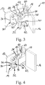
- the Fig. 4 shows a view of the hinge band 10 with the tensioning means 14 fixed and with the hinge axis element 20 fixed by the tensioning means 14.
- the joints 60, 62 are on one side of the clamping jaws 42, 44, 46, 48 and the screw connection 34 is on the other side of the clamping jaws 42 , 44, 46, 48 arranged. This results in a large lever and thus also a high clamping force.
- the Fig. 5 finally shows in a comparison those in the Figures 3 and 4 shown states of the hinge 10 in a plan view. It can be clearly seen that the clamping surfaces of the clamping jaws 40, 42; 46, 48 each pair of the circumference of the hinge axis element 20 in the corresponding axis section 24, 26 together almost completely, that is to say over 90% overlap.
Abstract
Description
- Die Erfindung betrifft ein Gelenkband, insbesondere für eine Pendeltür, mit (i) mindestens einem Gelenkachsenelement, (ii) einem ersten Bandteil und einem zweiten Bandteil, die über das mindestens eine Gelenkachsenelement scharnierartig miteinander verbunden sind, (iii) mindestens einer Rastanordnung, die mindestens eine an dem zweiten Bandteil angeordnete Rasteinrichtung mit einem Rastkörper und mindestens eine am Gelenkachsenelement angeordnete Rastausnehmung umfasst, wobei die Rasteinrichtung derart eingerichtet ist, dass der Rastkörper in einer Raststellung in die Rastausnehmung eingreift und (iv) einem Spannmittel für ein lösbares Fixieren des Gelenkachsenelements am ersten Bandteil, bei dem eine Winkelposition des Gelenkachsenelements und der Rastausnehmung bezüglich des ersten Bandteils einstellbar ist.
- Die Winkelstellung der beiden Bandteile bei in die Rastausnehmung eingerastetem Rastkörper, also in einer Raststellung, markiert einen Nullpunkt bezüglich eines Pendelns der Bandteile gegeneinander beziehungsweise einer entsprechenden Tür oder eines entsprechenden Fensters. Dieser Nullpunkt des Pendelns kann durch Verdrehen der beiden Bandteile gegeneinander bei gelöstem Spannmittel verlagert werden. Das Verdrehen erfolgt dabei in der Regel bei in die Rastausnehmung eingerastetem Rastkörper. In dieser Raststellung ist die Winkelposition des Gelenkachsenelements bezüglich des zweiten Bandteils wohldefiniert. Ist der Nullpunkt an der gewünschten Winkelstellung des ersten Bandteils gegenüber dem zweiten Bandteil, so wird die entsprechende Winkelposition des Gelenkachsenelements bezüglich des ersten Bandteils über das Spannmittel fixiert, wodurch der Nullpunkt eingestellt ist.
- Das Dokument
DE 10 2011 088 192 A1 beschreibt ein Gelenkband für eine Pendeltür, mit (i) mindestens einem Gelenkachsenelement, (ii) einem ersten Bandteil und einem zweiten Bandteil, die über das mindestens eine Gelenkachsenelement scharnierartig miteinander verbunden sind, (iii) mindestens einer Rastanordnung, die mindestens eine an dem zweiten Bandteil angeordnete Rasteinrichtung mit einem Rastkörper und mindestens eine am Gelenkachsenelement angeordnete Rastausnehmung umfasst, wobei die Rasteinrichtung derart eingerichtet ist, dass der Rastkörper in einer Raststellung in die Rastausnehmung eingreift und (iv) einem Spannmittel für ein lösbares Fixieren des Gelenkachsenelements am ersten Bandteil, bei dem eine Winkelposition des Gelenkachsenelements und der Rastausnehmung bezüglich des ersten Bandteils einstellbar ist. Das Spannmittel weist eine im/am Lagerelement gehaltene und als Gewindestift mit kegelförmiger Spitze ausgebildete Feststellschraube als Klemmelement auf, die zum Fixieren der gewählten Winkelposition des Gelenkachsenelements über eine Flanke dieser Spitze einseitig auf einen konisch ausgebildeten Endabschnitt dieses Gelenkachsenelements drückt. Die beim Spannen/Klemmen auftretende Kraft wirkt dabei nur auf eine sehr kleine strichartige Fläche, sodass ein entsprechend hoher Druck herrscht. Durch die einseitige Belastung kann es zu einem Verkannten/Verkippen des Gelenkachsenelements kommen, sodass die Kraft ungleichmäßig über die ohnehin schon kleine Fläche verteilt wird, sodass lokal ein recht hoher Druck entstehen kann. - Ein entsprechend hoher Druck kann jedoch dazu führen, dass auf dem Gelenkachsenelement Klemmmarken entstehen. Bei einer Korrektur der Nullpunkteinstellung können Klemmmarken zurückliegender Nullpunkteinstellungen die Nullpunkteinstellung erschweren, da das Rastmittel mit seinem Klemmelement in die alte Klemmmarke "hineingleitet" und die Nullpunkteinstellung auf einen alten Winkelpositions-Wert zurückfällt.
- Es ist Aufgabe der Erfindung ein Gelenkband anzugeben, bei dem derartige Probleme zumindest deutlich reduziert werden.
- Die Lösung der Aufgabe erfolgt erfindungsgemäß durch die Merkmale des unabhängigen Anspruchs. Bevorzugte Ausgestaltungen der Erfindung sind in den Unteransprüchen angegeben, die jeweils einzeln oder in Kombination einen Aspekt der Erfindung darstellen können.
- Bei dem erfindungsgemäßen Gelenkband, insbesondere für eine Pendeltür, mit
- (i) mindestens einem Gelenkachsenelement,
- (ii) einem ersten Bandteil und einem zweiten Bandteil, die über das mindestens eine Gelenkachsenelement scharnierartig miteinander verbunden sind,
- (iii) mindestens einer Rastanordnung, die mindestens eine an dem zweiten Bandteil angeordnete Rasteinrichtung mit einem Rastkörper und mindestens eine am Gelenkachsenelement angeordnete Rastausnehmung umfasst, wobei die Rasteinrichtung derart eingerichtet ist, dass der Rastkörper in einer Raststellung in die Rastausnehmung eingreift und
- (iv) einem Spannmittel für ein lösbares Fixieren des Gelenkachsenelements am ersten Bandteil, bei dem eine Winkelposition des Gelenkachsenelements und der Rastausnehmung bezüglich des ersten Bandteils einstellbar ist,
- Gemäß einer bevorzugten Ausgestaltung der Erfindung übergreifen die Klemmflächen jedes Klemmbacken-Paares den Umfang des Gelenkachsenelements in einem entsprechenden Achsabschnitt gemeinsam zu mindestens 33%, vorzugsweise zu mindestens 50%. Bei 33% sind dies zum Beispiel zwei einander gegenüberliegende Umfangskreisbögen von je 60°, also 120° (= 33% von 360°) zusammen. Bei 50% sind dies zwei einander gegenüberliegende Umfangskreisbögen von je 90°, also 180° zusammen. Die bei diesen Abmessungen entstehenden Klemmmarken sind in der Regel kaum nachweisbar.
- Gemäß einer weiteren bevorzugten Ausgestaltung der Erfindung weist das Spannmittel einen festgelegten Einspann-Zustand mit wohldefinierter Klemmkraft der Klemmbacken bezüglich des Gelenkachsenelements auf. In diesen Zustand kann das Spannmittel wahlweise verbracht und in diesem Zustand auch gehalten werden. Die Klemmkraft kann so gewählt sein, dass eine Klemmmarke bei einem Gelenkband mit derartigem Spannmittel zwar zu einer verringerten Klemmkraft führen könnte, jedoch nicht zu einem "Hineingleiten" in die alte Klemmmarke.
- Gemäß noch einer weiteren bevorzugten Ausgestaltung der Erfindung weist das Spannmittel zwei Spannmittel-Teile auf, von denen jedes Teil je eine Klemmbacke pro Paar Klemmbacken umfasst. Mit anderen Worten werden n (mit n = 1, 2, ...) Klemmbackenpaare über nur zwei Spannmittel-Teile gebildet. Die beiden Spannmittel müssen dabei gegeneinander bewegbar sein.
- Gemäß einer weiteren bevorzugten Ausgestaltung der Erfindung ist vorgesehen, dass das Spannmittel mindestens eine Einrichtung zum Festlegen einer Relativposition der Spannmittel-Teile untereinander, insbesondere in Form einer Verschraubung, aufweist, bei der sich die Klemmbacken in einer die Winkelposition des Gelenkachsenelements klemmend fixierenden Klemmposition befinden. Dies ist dann der vorstehend genannte "festgelegte Einspann-Zustand".
- Weiterhin ist dabei mit Vorteil vorgesehen, dass jedes der beiden gegeneinander bewegbaren Spannmittel-Teile eine Basis und mindestens einen Arm aufweist, an dem die Klemmbacke für das entsprechende Klemmbackenpaar beabstanded von der Basis angeordnet ist. Anders als bei dem eingangs genannten Dokument
DE 10 2011 088 192 A1 wird hier die Verschraubung nicht direkt zum Spannen/Klemmen genutzt, sondern zum Festlegen der Relativposition der Spannmittel-Teile untereinander durch Befestigen der Spannmittel-Teile aneinander. - Dabei ist mit Vorteil vorgesehen, dass die Einrichtung zum Festlegen einer Relativposition der Spannmittel-Teile untereinander jeweils an der Basis der beteiligten Spannmittel-Teile angreift. Ist diese Einrichtung eine Verschraubung, so ist diese bevorzugt eine zentrale Verschraubung, insbesondere mittels nur einer Schraube.
- Weiterhin ist insbesondere vorgesehen, dass die Spannmittelteile die Basis und zwei Arme umfasst, die U-förmig angeordnet sind. Über diese U-Form können die zwei gegeneinander bewegbare Spannmittel-Teile beispielsweise ein einzelnes Gelenkachsenelement an seinen beiden Enden klemmend fixieren.
- Gemäß noch einer weiteren bevorzugten Ausgestaltung der Erfindung ist die Kontur des mindestens einen Gelenkachsenelements kreiszylinderförmig, wobei die Klemmflächen der Klemmbacken entsprechend angepasst sind. Jede der Klemmbacken bildet dazu in Bezug auf ihre jeweilige Klemmfläche beispielsweise eine Art Halbschale.
- Weiterhin ist bevorzugt vorgesehen, dass die Rasteinrichtung eine Vorrichtung zur Kraftbeaufschlagung des Rastkörpers aufweist. Dabei ist mit Vorteil vorgesehen, dass die Vorrichtung zur Kraftbeaufschlagung des Rastkörpers eine Federeinrichtung, insbesondere eine Druckfeder, umfasst. Eine solche Federbeaufschlagung hat sich in der Praxis bewährt.
- Nachfolgend wird die Erfindung unter Bezugnahme auf die anliegenden Zeichnungen anhand von bevorzugten Ausführungsbeispielen exemplarisch erläutert, wobei die nachfolgend dargestellten Merkmale sowohl jeweils einzeln als auch in Kombination einen Aspekt der Erfindung darstellen können. Es zeigen:
- Fig. 1
- Baugruppen eines Gelenkbandes für eine Pendeltür gemäß einer bevorzugten Ausgestaltung der Erfindung,
- Fig. 2
- einen Schnitt durch die Baugruppe des Gelenkbandes, in der ein Gelenkachsenelement gelagert ist,
- Fig. 3
- eine 3D-Ansicht des Gelenkbandes mit gelöstem Spannmittel,
- Fig. 4
- eine 3D-Ansicht des Gelenkbandes mit per Spannmittel fixiertem Gelenkachsenelement und,
- Fig. 5
- eine Gegenüberstellung der in den
Figuren 3 und 4 gezeigten Zustände des Gelenkbandes in einer Draufsicht. - Die
Fig. 1 zeigt die Baugruppen eines Gelenkbandes 10, genauer gesagt eines Gelenkbandes für eine (nicht gezeigte) Pendeltür, insbesondere eine Glaspendeltür. Die erste Baugruppe weist ein erstes Bandteil 12 und ein Spannmittel 14 auf. Die zweite Baugruppe weist ein zweites Bandteil 16 sowie eine am zweiten Bandteil 16 befestigte Lagereinheit 18 auf, in der ein stiftartiges Gelenkachsenelement 20 über eine Lagerbuchse 22 drehbar gelagert ist. Dabei ragt das Gelenkachsenelement 20 mit seinen Endabschnitten 24, 26 auf einander gegenüberliegenden Seiten aus der Lagereinheit 18 hinaus. Innerhalb der Lagereinheit 18 ergibt sich eine inFig. 2 gezeigte Rastanordnung 28, über die ein Nullpunkt der Pendelbewegung der Pendeltür definiert ist. Das Spannmittel 14 weist zwei voneinander separierbare Spannmittel-Teile 30, 32 auf, von denen das erste Spannmittel-Teil 30 am ersten Bandteil 12 befestigt ist während das zweite Spannmittel-Teil 32 über eine Verschraubung 34 am ersten Spannmittel-Teil 30 lösbar befestigt werden kann. Die Verschraubung 34 bildet zusammen mit Vorsprung-Ausnehmungs-Anordnungen eine Einrichtung zum Festlegen einer Relativposition der Spannmittel-Teile untereinander. - Hier im gezeigten Beispiel ist das erste Bandteil 12 ein Bandteil für ein Türblatt der Pendeltür und das zweite Bandteil 16 ein Bandteil zur Befestigung an einer Türzarge, einer Wand oder einem anderen feststehenden Element. Alternativ ist es ist auch möglich und bei entsprechenden Ausgestaltungen auch üblich, dass das zweite Bandteil 16 das Bandteil für das Türblatt der Pendeltür und das erste Bandteil 12 ein Bandteil zur Befestigung an einem entsprechenden feststehenden Element ist. Die beiden Bandteile 12, 16 sind innerhalb des montierten Gelenkbandes 10 über das Gelenkachsenelement 20 scharnierartig miteinander verbunden. Über eine Raststellung der Rastanordnung 28 ergibt sich wie gesagt ein Nullpunkt der Pendelbewegung der Pendeltür. Um nun diesen Nullpunkt einer Winkelstellung der Pendeltür bzw. des ersten Bandteils 12 zuzuordnen, kann man das Gelenkachsenelement 20 über das Spannmittel 14 so am ersten Bandteil 12 lösbar fixieren, das eine gewünschte Winkelposition des Gelenkachsenelements 20 bezüglich des ersten Bandteils 12 einstellbar ist.
- Jedes der gegeneinander bewegbaren Spannmittel-Teile 30, 32 weist eine U-förmige Gestalt mit einer Basis 36 und zwei Armen 38, 40 auf, wobei die Verschraubung 34 jeweils an der Basis 36 erfolgt. Das Spannmittel 14 weist insgesamt zwei Paar Klemmbacken 42, 44, 46, 48 auf, von denen das eine Paar (mit den Klemmbacken 42, 44) das Gelenkachsenelement 20 an seinem einen Endabschnitt 24 und das andere Paar (mit den Klemmbacken 46, 48) das Gelenkachsenelement 20 an seinem anderen Endabschnitt 26 umfänglich umgreifen und dabei lösbar festklemmen kann. Dabei weist jedes der Spannmittel-Teile 30, 32 in einem Mittelabschnitt seiner Arme 38, 40 je eine Klemmbacke 46, 48 pro Paar Klemmbacken 42, 44 auf.
- Die
Fig. 2 zeigt einen Schnitt durch die zweite Baugruppe des Gelenkbandes 10, wobei der Schnitt durch die Lagereinheit 18 auf Höhe des Gelenkachsenelements 20 geht. In der Lagereinheit 18 befindet sich -neben dem Gelenkachsenelement 20 und der Lagerbuchse 22 zur Lagerung des Gelenkachsenelements 20- auch die Rastanordnung 28, welche eine Rasteinrichtung 50 mit einem Rastkörper 52 und einer Vorrichtung 54 zur Kraftbeaufschlagung des Rastkörpers 52 sowie eine im Gelenkachsenelement 20 ausgebildete Rastausnehmung 56 umfasst. Die Vorrichtung 54 zur Kraftbeaufschlagung des Rastkörpers 52 ist im Wesentlichen eine Druckfeder 58, die den Rastkörper 52 in Richtung eines Achsabschnittes des Gelenkachsenelements 20 drückt, in dem die Rastausnehmung 56 ausgebildet ist. Mit anderen Worten ist die Rasteinrichtung 50 so eingerichtet, dass der Rastkörper 52 in einer Raststellung in die Rastausnehmung 56 eingreift. - Die Winkelstellung der beiden Bandteile 12, 16 bei in die Rastausnehmung 56 eingerastetem Rastkörper 52, also in einer Raststellung, markiert einen Nullpunkt bezüglich eines Pendelns der Bandteile 12, 16 gegeneinander beziehungsweise einer entsprechenden Tür oder eines entsprechenden Fensters. Dieser Nullpunkt des Pendelns kann durch Verdrehen der beiden Bandteile 12, 16 gegeneinander bei gelöstem Spannmittel 14 verlagert werden. Das Verdrehen erfolgt dabei in der Regel bei in die Rastausnehmung 56 eingerastetem Rastkörper 52. In dieser Raststellung ist die Winkelposition des Gelenkachsenelements 20 bezüglich des zweiten Bandteils 12 wohldefiniert. Ist der Nullpunkt an der gewünschten Winkelstellung des ersten Bandteils 12 gegenüber dem zweiten Bandteil 16, so wird die entsprechende Winkelposition des Gelenkachsenelements 20 bezüglich des ersten Bandteils 12 über das Spannmittel 14 fixiert, wodurch der Nullpunkt eingestellt ist. Dazu wird bei entsprechender Winkelstellung einfach die Schraube der Verschraubung 34 angezogen.
- Die
Fig. 3 zeigt eine Ansicht des Gelenkbandes 10 mit gelöstem Spannmittel 14.In dieser Darstellung ist erkennbar, dass die freien Enden der einander zugeordneten Arme 38, 40 der beiden Spannmittel-Teile 30, 32 Gelenke 60, 62 bezüglich einer gemeinsamen Drehachse 64 bilden. Die Spannmittel-Teile 30, 32 sind bezüglich dieser Achse 64 gegeneinander schwenkbar. Das Gelenkachsenelement 20 ist bezüglich des ersten Bandteils 12 nicht fixiert. - Die
Fig. 4 zeigt eine Ansicht des Gelenkbandes 10 mit fixiertem Spannmittel 14 und mit per Spannmittel 14 fixiertem Gelenkachsenelement 20. Dabei sind die Gelenke 60, 62 auf der einen Seite der Klemmbacken 42, 44, 46, 48 und die Verschraubung 34 auf der anderen Seite der Klemmbacken 42, 44, 46, 48 angeordnet. Dadurch ergibt sich ein großer Hebel und somit auch eine hohe Klemmkraft. - Die
Fig. 5 zeigt schließlich in einer Gegenüberstellung die in denFiguren 3 und 4 gezeigten Zustände des Gelenkbandes 10 in einer Draufsicht. Dabei ist gut erkennbar, dass die Klemmflächen der Klemmbacken 40, 42; 46, 48 jedes Paares des Umfang des Gelenkachsenelements 20 in dem entsprechenden Achsabschnitt 24, 26 gemeinsam fast vollständig, also zu über 90%, übergreifen. -
- 10
- Gelenkband
- 12
- erstes Bandteil
- 14
- Spannmittel
- 16
- zweites Bandteil
- 18
- Lagereinheit
- 20
- Gelenkachsenelement
- 22
- Lagerbuchse
- 24, 26
- Endabschnitt (Gelenkachsenelement)
- 28
- Rastanordnung
- 30
- erstes Spannmittel-Teil
- 32
- zweites Spannmittel-Teil
- 34
- Verschraubung
- 36
- Basis
- 38, 40
- Arm
- 42, 44
- Klemmbacke (erstes Paar)
- 46, 48
- Klemmbacke (zweites Paar)
- 50
- Rasteinrichtung
- 52
- Rastkörper
- 54
- Vorrichtung zur Kraftbeaufschlagung
- 56
- Rastausnehmung
- 58
- Druckfeder
- 60, 62
- Gelenk
- 64
- Drehachse
Claims (10)
- Gelenkband (10), insbesondere für eine Pendeltür, mit- mindestens einem Gelenkachsenelement (20),- einem ersten Bandteil (12) und einem zweiten Bandteil (16), die über das mindestens eine Gelenkachsenelement (20) scharnierartig miteinander verbunden sind,- mindestens einer Rastanordnung (28), die mindestens eine an dem zweiten Bandteil (16) angeordnete Rasteinrichtung (50) mit einem Rastkörper (52) und mindestens eine am Gelenkachsenelement (20) angeordnete Rastausnehmung (56) umfasst, wobei die Rasteinrichtung (50) derart eingerichtet ist, dass der Rastkörper (52) in einer Raststellung in die Rastausnehmung (56) eingreift unddadurch gekennzeichnet, dass mehrere Paare von Klemmbacken (42, 44; 46, 48) vorgesehen sind und jedes der gegeneinander bewegbaren Spannmittel-Teile (30, 32) eine Basis (36) und mehrere Arme (38, 40) aufweist, an denen die jeweilige Klemmbacke (42, 44; 46, 48) für das entsprechende Paar Klemmbacken (42, 44; 46, 48) beabstandet von der Basis (36) angeordnet ist.- einem Spannmittel (14) für ein lösbares Fixieren des Gelenkachsenelements (20) am ersten Bandteil (12), bei dem eine Winkelposition des Gelenkachsenelements (20) und der Rastausnehmung (56) bezüglich des ersten Bandteils (12) einstellbar ist, wobei das Spannmittel (14) mindestens ein Paar Klemmbacken (42, 44; 46, 48) zum Einspannen des Gelenkachsenelements (20) zwischen diesen Klemmbacken (42, 44; 46, 48) aufweist, wobei jede der Klemmbacken (42, 44; 46, 48) eine an die Kontur des Gelenkachsenelements (20) angepasste Klemmfläche aufweist und das Spannmittel (14) zwei Spannmittel-Teile (30, 32) umfasst, von denen jedes Spannmittel-Teil (30, 32) je eine Klemmbacke (42, 44; 46, 48) pro Paar aufweist,
- Gelenkband nach Anspruch 1, dadurch gekennzeichnet, dass die zwei Spannmittel-Teile (30, 32) voneinander separierbare Spannmittel-Teile (30, 32) sind.
- Gelenkband nach Anspruch 1 oder 2, dadurch gekennzeichnet, dass jeder der Arme (38, 40) ein freies Ende aufweist, wobei die freien Enden der einander zugeordneten Arme (38, 40) der beiden Spannmittel-Teile (30, 32) Gelenke (60, 62) bezüglich einer gemeinsamen Drehachse (64) bilden, bezüglich der die Spannmittel-Teile (30, 32) gegeneinander schwenkbar sind.
- Gelenkband nach einem der Ansprüche 1 bis 3, dadurch gekennzeichnet, dass die Klemmflächen der Klemmbacken (42, 44; 46, 48) jedes Klemmbacken-Paares den Umfang des Gelenkachsenelements (20) in einem entsprechenden Achsabschnitt (24, 26) gemeinsam zu mindestens 33%, vorzugsweise zu mindestens 50% übergreifen.
- Gelenkband nach einem der Ansprüche 1 bis 4, dadurch gekennzeichnet, dass das Spannmittel (14) einen festgelegten Einspann-Zustand mit wohldefinierter Klemmkraft der Klemmbacken (42, 44; 46, 48) bezüglich des Gelenkachsenelements (20) aufweist.
- Gelenkband nach Anspruch 1, dadurch gekennzeichnet, dass das Spannmittel (14) mindestens eine Verschraubung (34) oder eine sonstige Einrichtung zum Festlegen einer Relativposition der Spannmittel-Teile (30, 32) untereinander aufweist, bei der sich die Klemmbacken (42, 44; 46, 48) in einer die Winkelposition des Gelenkachsenelements (20) klemmend fixierenden Klemmposition befinden.
- Gelenkband nach Anspruch 1, dadurch gekennzeichnet, dass die Einrichtung (34) zum Festlegen der Relativposition der Spannmittel-Teile (30, 32) untereinander jeweils an der Basis (36) der beteiligten Spannmittel-Teile (30, 32) angreift.
- Gelenkband nach Anspruch 6 oder 7, dadurch gekennzeichnet, dass die Spannmittel-Teile die Basis (36) und zwei Arme (38, 40) umfassen, die U-förmig angeordnet sind.
- Gelenkband nach einem der Ansprüche 1 bis 8, dadurch gekennzeichnet, dass die Kontur des mindestens einen Gelenkachsenelements (20) kreiszylinderförmig ist und die Klemmflächen der Klemmbacken (42, 44; 46, 48) entsprechend angepasst sind.
- Gelenkband nach einem der Ansprüche 1 bis 9, dadurch gekennzeichnet, dass die Rasteinrichtung (50) eine Vorrichtung (54) zur Kraftbeaufschlagung des Rastkörpers (52) aufweist.
Applications Claiming Priority (1)
| Application Number | Priority Date | Filing Date | Title |
|---|---|---|---|
| DE102019113555.9A DE102019113555B3 (de) | 2019-05-21 | 2019-05-21 | Gelenkband |
Publications (2)
| Publication Number | Publication Date |
|---|---|
| EP3741944A1 true EP3741944A1 (de) | 2020-11-25 |
| EP3741944B1 EP3741944B1 (de) | 2023-03-29 |
Family
ID=70802715
Family Applications (1)
| Application Number | Title | Priority Date | Filing Date |
|---|---|---|---|
| EP20175855.4A Active EP3741944B1 (de) | 2019-05-21 | 2020-05-20 | Gelenkband |
Country Status (6)
| Country | Link |
|---|---|
| US (2) | US20200370353A1 (de) |
| EP (1) | EP3741944B1 (de) |
| CN (1) | CN111980510B (de) |
| CA (1) | CA3081313C (de) |
| DE (1) | DE102019113555B3 (de) |
| TW (1) | TWI724908B (de) |
Citations (4)
| Publication number | Priority date | Publication date | Assignee | Title |
|---|---|---|---|---|
| DE3901395A1 (de) * | 1989-01-19 | 1990-08-02 | Munch Paul Jean | Schwenktuere fuer duschtrennwand |
| FR2886965A1 (fr) * | 2005-06-10 | 2006-12-15 | Ko Ming Cheng | Charniere ajustable pour une porte en verre |
| DE102011088192A1 (de) | 2011-12-09 | 2013-06-13 | Kl Megla Gmbh | Gelenkband für Türen oder Fenster |
| WO2017051328A1 (en) * | 2015-09-24 | 2017-03-30 | Mgt Industries S.R.L. | Hinge for revolving shutters, especially of shower boxes |
Family Cites Families (23)
| Publication number | Priority date | Publication date | Assignee | Title |
|---|---|---|---|---|
| US3828394A (en) * | 1971-01-18 | 1974-08-13 | Blumcraft Pittsburgh | Hinge-device and method |
| US5079798A (en) * | 1990-08-13 | 1992-01-14 | Anthony Burke | Glass hinge assembly |
| US5867869A (en) * | 1994-10-06 | 1999-02-09 | Chmi | Pressure hinge device for glass door or panel |
| US20020066160A1 (en) * | 2000-12-05 | 2002-06-06 | Fanny Chiang | Auto-returning device of a hinge for a glass door |
| US6526627B2 (en) * | 2000-12-05 | 2003-03-04 | Fanny Chiang | Hinge auto-return device for a glass door |
| US6560821B2 (en) * | 2001-02-09 | 2003-05-13 | The Group Legacy L.C. | Glass door hinge |
| US6481055B2 (en) * | 2001-04-10 | 2002-11-19 | Ko Ming Cheng | Pivotal device for a frameless glass door |
| US20060162124A1 (en) * | 2005-01-25 | 2006-07-27 | Ching-Yi Lin | Glass door hinge structure |
| US7188390B2 (en) * | 2005-03-15 | 2007-03-13 | Ko-Ming Cheng | Adjustable hinge for a glass door |
| DE102005025278B3 (de) | 2005-06-02 | 2006-10-12 | Gang Gwo Industrial Co., Ltd., Ta Liao | Einstellbares Scharnier für eine Glastür |
| US20090188082A1 (en) * | 2008-01-25 | 2009-07-30 | Shih-Chang Huang | Adjustable glass hinge |
| US20100275410A1 (en) * | 2009-05-01 | 2010-11-04 | Door & Window Hardware Co. | Automatic positioning hinge |
| GB2472883B (en) * | 2009-08-18 | 2012-01-11 | Chung Chow | Damped door hinge |
| TW201326527A (zh) * | 2011-12-21 | 2013-07-01 | Gang Gwo Ind Co Ltd | 油壓鉸鍊 |
| US20140068893A1 (en) * | 2012-09-07 | 2014-03-13 | E Tai Enterprise Co., Ltd. | Door damping apparatus and manufacturing method thereof |
| CN203175230U (zh) * | 2013-03-28 | 2013-09-04 | 中山市福瑞卫浴设备有限公司 | 用于淋浴房的链式铰链 |
| WO2014169332A1 (en) * | 2013-04-15 | 2014-10-23 | Stuart Michael Christopher | A hinge |
| US9140043B2 (en) * | 2013-08-01 | 2015-09-22 | Door & Window Hardware Co. | Hydraulic hinge buffer assembly for a door |
| DE102013219201B3 (de) * | 2013-09-24 | 2014-10-23 | KL-BeschIäge Karl Loggen GmbH | Gelenkband für ein Trennelement, insbesondere für eine Pendeltür |
| CN104453512A (zh) * | 2014-09-05 | 2015-03-25 | 中山市福瑞卫浴设备有限公司 | 一种链式铰链 |
| GB201704958D0 (en) * | 2017-03-28 | 2017-05-10 | Chow Nga Ching | Adjustable hinge |
| CN108756552A (zh) * | 2018-07-16 | 2018-11-06 | 佛山市远阳五金制品有限公司 | 一种90度自动回位阻尼合页 |
| US10563443B1 (en) * | 2019-03-20 | 2020-02-18 | Ever Yang Industry Co., Ltd. | Door hinge |
-
2019
- 2019-05-21 DE DE102019113555.9A patent/DE102019113555B3/de active Active
-
2020
- 2020-05-20 EP EP20175855.4A patent/EP3741944B1/de active Active
- 2020-05-20 CA CA3081313A patent/CA3081313C/en active Active
- 2020-05-20 US US16/879,004 patent/US20200370353A1/en not_active Abandoned
- 2020-05-21 CN CN202010435734.8A patent/CN111980510B/zh active Active
- 2020-05-21 TW TW109116840A patent/TWI724908B/zh active
-
2021
- 2021-02-24 US US17/184,564 patent/US11603688B2/en active Active
Patent Citations (4)
| Publication number | Priority date | Publication date | Assignee | Title |
|---|---|---|---|---|
| DE3901395A1 (de) * | 1989-01-19 | 1990-08-02 | Munch Paul Jean | Schwenktuere fuer duschtrennwand |
| FR2886965A1 (fr) * | 2005-06-10 | 2006-12-15 | Ko Ming Cheng | Charniere ajustable pour une porte en verre |
| DE102011088192A1 (de) | 2011-12-09 | 2013-06-13 | Kl Megla Gmbh | Gelenkband für Türen oder Fenster |
| WO2017051328A1 (en) * | 2015-09-24 | 2017-03-30 | Mgt Industries S.R.L. | Hinge for revolving shutters, especially of shower boxes |
Also Published As
| Publication number | Publication date |
|---|---|
| CA3081313C (en) | 2021-06-15 |
| CN111980510A (zh) | 2020-11-24 |
| US11603688B2 (en) | 2023-03-14 |
| TWI724908B (zh) | 2021-04-11 |
| CA3081313A1 (en) | 2020-11-21 |
| TW202043599A (zh) | 2020-12-01 |
| US20210180378A1 (en) | 2021-06-17 |
| CN111980510B (zh) | 2022-01-28 |
| DE102019113555B3 (de) | 2020-07-23 |
| US20200370353A1 (en) | 2020-11-26 |
| EP3741944B1 (de) | 2023-03-29 |
Similar Documents
| Publication | Publication Date | Title |
|---|---|---|
| EP1976735B1 (de) | Scheibenwischvorrichtung, insbesondere für ein kraftfahrzeug | |
| EP3030209B1 (de) | Spannklaue zur anbringung an einer gleitschiene eines operationstisches | |
| EP3333374A1 (de) | Leitschaufelverstellung mit seitlich montiertem verstellhebel und zugehöriges verfahren zur herstellung der zugehörigen verbindung | |
| DE2239853B2 (de) | Haltevorrichtung fuer aussenrueckblickspiegel von kraftfahrzeugen o.dgl. | |
| EP1742008A1 (de) | Vorrichtung zur Befestigung eines auf bzw. an einem Körper zu befestigenden Teils | |
| EP2097199B1 (de) | Systempendelvorrichtung und verfahren | |
| EP1201945B1 (de) | Befestigungselement | |
| EP2283972B1 (de) | Fixierelement | |
| EP2197692B1 (de) | Zirkel mit gelenk und arretiereinrichtung | |
| WO1998038921A1 (de) | Lösbare halterung für ein blatt am haltearm eines chirurgischen retraktors | |
| DE3715496A1 (de) | Zweiteiliges verbindungselement zum justierbaren verbinden zweier bauteile | |
| EP3741944A1 (de) | Gelenkband | |
| EP3171120B1 (de) | Montagevorrichtung für eine zieleinrichtung an einer handfeuerwaffe | |
| EP1508318B1 (de) | Orthopädische Schiene | |
| DE3719483C2 (de) | ||
| EP3036065B1 (de) | Schraubzwinge | |
| EP0548622B1 (de) | Arretiervorrichtung | |
| DE4239960C2 (de) | Antennenfuß | |
| DE2914568C2 (de) | Werkzeughalter für Schneidwerkzeuge | |
| EP2528177A2 (de) | Vorrichtung zur Montage eines Schalters oder dergleichen an einer Montageplatte | |
| DE10150916B4 (de) | Gelenkband, insbesondere für Glaspendeltüren | |
| DE102015108710B4 (de) | Spannelement für eine Spannvorrichtung, sowie Spannvorrichtung | |
| DE4139259A1 (de) | Spanneinrichtung zum spannen zweier werkstuecke | |
| DE2720366C3 (de) | Vorrichtung zur Schnell- und Feineinstellung an Zirkeln | |
| EP4051912A1 (de) | Bolzen mit verstellbarem spannbereich |
Legal Events
| Date | Code | Title | Description |
|---|---|---|---|
| PUAI | Public reference made under article 153(3) epc to a published international application that has entered the european phase |
Free format text: ORIGINAL CODE: 0009012 |
|
| STAA | Information on the status of an ep patent application or granted ep patent |
Free format text: STATUS: THE APPLICATION HAS BEEN PUBLISHED |
|
| AK | Designated contracting states |
Kind code of ref document: A1 Designated state(s): AL AT BE BG CH CY CZ DE DK EE ES FI FR GB GR HR HU IE IS IT LI LT LU LV MC MK MT NL NO PL PT RO RS SE SI SK SM TR |
|
| AX | Request for extension of the european patent |
Extension state: BA ME |
|
| STAA | Information on the status of an ep patent application or granted ep patent |
Free format text: STATUS: REQUEST FOR EXAMINATION WAS MADE |
|
| 17P | Request for examination filed |
Effective date: 20210525 |
|
| RBV | Designated contracting states (corrected) |
Designated state(s): AL AT BE BG CH CY CZ DE DK EE ES FI FR GB GR HR HU IE IS IT LI LT LU LV MC MK MT NL NO PL PT RO RS SE SI SK SM TR |
|
| GRAP | Despatch of communication of intention to grant a patent |
Free format text: ORIGINAL CODE: EPIDOSNIGR1 |
|
| STAA | Information on the status of an ep patent application or granted ep patent |
Free format text: STATUS: GRANT OF PATENT IS INTENDED |
|
| INTG | Intention to grant announced |
Effective date: 20221011 |
|
| GRAS | Grant fee paid |
Free format text: ORIGINAL CODE: EPIDOSNIGR3 |
|
| GRAA | (expected) grant |
Free format text: ORIGINAL CODE: 0009210 |
|
| STAA | Information on the status of an ep patent application or granted ep patent |
Free format text: STATUS: THE PATENT HAS BEEN GRANTED |
|
| AK | Designated contracting states |
Kind code of ref document: B1 Designated state(s): AL AT BE BG CH CY CZ DE DK EE ES FI FR GB GR HR HU IE IS IT LI LT LU LV MC MK MT NL NO PL PT RO RS SE SI SK SM TR |
|
| REG | Reference to a national code |
Ref country code: CH Ref legal event code: EP |
|
| REG | Reference to a national code |
Ref country code: DE Ref legal event code: R096 Ref document number: 502020002839 Country of ref document: DE |
|
| REG | Reference to a national code |
Ref country code: AT Ref legal event code: REF Ref document number: 1556753 Country of ref document: AT Kind code of ref document: T Effective date: 20230415 |
|
| REG | Reference to a national code |
Ref country code: IE Ref legal event code: FG4D Free format text: LANGUAGE OF EP DOCUMENT: GERMAN |
|
| REG | Reference to a national code |
Ref country code: SE Ref legal event code: TRGR |
|
| REG | Reference to a national code |
Ref country code: NL Ref legal event code: FP |
|
| REG | Reference to a national code |
Ref country code: LT Ref legal event code: MG9D |
|
| PG25 | Lapsed in a contracting state [announced via postgrant information from national office to epo] |
Ref country code: RS Free format text: LAPSE BECAUSE OF FAILURE TO SUBMIT A TRANSLATION OF THE DESCRIPTION OR TO PAY THE FEE WITHIN THE PRESCRIBED TIME-LIMIT Effective date: 20230329 Ref country code: NO Free format text: LAPSE BECAUSE OF FAILURE TO SUBMIT A TRANSLATION OF THE DESCRIPTION OR TO PAY THE FEE WITHIN THE PRESCRIBED TIME-LIMIT Effective date: 20230629 Ref country code: LV Free format text: LAPSE BECAUSE OF FAILURE TO SUBMIT A TRANSLATION OF THE DESCRIPTION OR TO PAY THE FEE WITHIN THE PRESCRIBED TIME-LIMIT Effective date: 20230329 Ref country code: LT Free format text: LAPSE BECAUSE OF FAILURE TO SUBMIT A TRANSLATION OF THE DESCRIPTION OR TO PAY THE FEE WITHIN THE PRESCRIBED TIME-LIMIT Effective date: 20230329 Ref country code: HR Free format text: LAPSE BECAUSE OF FAILURE TO SUBMIT A TRANSLATION OF THE DESCRIPTION OR TO PAY THE FEE WITHIN THE PRESCRIBED TIME-LIMIT Effective date: 20230329 |
|
| PGFP | Annual fee paid to national office [announced via postgrant information from national office to epo] |
Ref country code: NL Payment date: 20230519 Year of fee payment: 4 Ref country code: IT Payment date: 20230531 Year of fee payment: 4 Ref country code: FR Payment date: 20230526 Year of fee payment: 4 Ref country code: DE Payment date: 20230524 Year of fee payment: 4 |
|
| PG25 | Lapsed in a contracting state [announced via postgrant information from national office to epo] |
Ref country code: GR Free format text: LAPSE BECAUSE OF FAILURE TO SUBMIT A TRANSLATION OF THE DESCRIPTION OR TO PAY THE FEE WITHIN THE PRESCRIBED TIME-LIMIT Effective date: 20230630 Ref country code: FI Free format text: LAPSE BECAUSE OF FAILURE TO SUBMIT A TRANSLATION OF THE DESCRIPTION OR TO PAY THE FEE WITHIN THE PRESCRIBED TIME-LIMIT Effective date: 20230329 |
|
| PGFP | Annual fee paid to national office [announced via postgrant information from national office to epo] |
Ref country code: SE Payment date: 20230519 Year of fee payment: 4 |
|
| PG25 | Lapsed in a contracting state [announced via postgrant information from national office to epo] |
Ref country code: SM Free format text: LAPSE BECAUSE OF FAILURE TO SUBMIT A TRANSLATION OF THE DESCRIPTION OR TO PAY THE FEE WITHIN THE PRESCRIBED TIME-LIMIT Effective date: 20230329 Ref country code: RO Free format text: LAPSE BECAUSE OF FAILURE TO SUBMIT A TRANSLATION OF THE DESCRIPTION OR TO PAY THE FEE WITHIN THE PRESCRIBED TIME-LIMIT Effective date: 20230329 Ref country code: PT Free format text: LAPSE BECAUSE OF FAILURE TO SUBMIT A TRANSLATION OF THE DESCRIPTION OR TO PAY THE FEE WITHIN THE PRESCRIBED TIME-LIMIT Effective date: 20230731 Ref country code: ES Free format text: LAPSE BECAUSE OF FAILURE TO SUBMIT A TRANSLATION OF THE DESCRIPTION OR TO PAY THE FEE WITHIN THE PRESCRIBED TIME-LIMIT Effective date: 20230329 Ref country code: EE Free format text: LAPSE BECAUSE OF FAILURE TO SUBMIT A TRANSLATION OF THE DESCRIPTION OR TO PAY THE FEE WITHIN THE PRESCRIBED TIME-LIMIT Effective date: 20230329 |
|
| PG25 | Lapsed in a contracting state [announced via postgrant information from national office to epo] |
Ref country code: SK Free format text: LAPSE BECAUSE OF FAILURE TO SUBMIT A TRANSLATION OF THE DESCRIPTION OR TO PAY THE FEE WITHIN THE PRESCRIBED TIME-LIMIT Effective date: 20230329 Ref country code: PL Free format text: LAPSE BECAUSE OF FAILURE TO SUBMIT A TRANSLATION OF THE DESCRIPTION OR TO PAY THE FEE WITHIN THE PRESCRIBED TIME-LIMIT Effective date: 20230329 Ref country code: IS Free format text: LAPSE BECAUSE OF FAILURE TO SUBMIT A TRANSLATION OF THE DESCRIPTION OR TO PAY THE FEE WITHIN THE PRESCRIBED TIME-LIMIT Effective date: 20230729 |
|
| REG | Reference to a national code |
Ref country code: CH Ref legal event code: PL |
|
| REG | Reference to a national code |
Ref country code: DE Ref legal event code: R097 Ref document number: 502020002839 Country of ref document: DE |
|
| PG25 | Lapsed in a contracting state [announced via postgrant information from national office to epo] |
Ref country code: MC Free format text: LAPSE BECAUSE OF FAILURE TO SUBMIT A TRANSLATION OF THE DESCRIPTION OR TO PAY THE FEE WITHIN THE PRESCRIBED TIME-LIMIT Effective date: 20230329 |
|
| REG | Reference to a national code |
Ref country code: BE Ref legal event code: MM Effective date: 20230531 |
|
| PG25 | Lapsed in a contracting state [announced via postgrant information from national office to epo] |
Ref country code: MC Free format text: LAPSE BECAUSE OF FAILURE TO SUBMIT A TRANSLATION OF THE DESCRIPTION OR TO PAY THE FEE WITHIN THE PRESCRIBED TIME-LIMIT Effective date: 20230329 Ref country code: LU Free format text: LAPSE BECAUSE OF NON-PAYMENT OF DUE FEES Effective date: 20230520 Ref country code: LI Free format text: LAPSE BECAUSE OF NON-PAYMENT OF DUE FEES Effective date: 20230531 Ref country code: DK Free format text: LAPSE BECAUSE OF FAILURE TO SUBMIT A TRANSLATION OF THE DESCRIPTION OR TO PAY THE FEE WITHIN THE PRESCRIBED TIME-LIMIT Effective date: 20230329 Ref country code: CZ Free format text: LAPSE BECAUSE OF FAILURE TO SUBMIT A TRANSLATION OF THE DESCRIPTION OR TO PAY THE FEE WITHIN THE PRESCRIBED TIME-LIMIT Effective date: 20230329 Ref country code: CH Free format text: LAPSE BECAUSE OF NON-PAYMENT OF DUE FEES Effective date: 20230531 |
|
| PLBE | No opposition filed within time limit |
Free format text: ORIGINAL CODE: 0009261 |
|
| STAA | Information on the status of an ep patent application or granted ep patent |
Free format text: STATUS: NO OPPOSITION FILED WITHIN TIME LIMIT |
|
| REG | Reference to a national code |
Ref country code: IE Ref legal event code: MM4A |
|
| 26N | No opposition filed |
Effective date: 20240103 |
|
| PG25 | Lapsed in a contracting state [announced via postgrant information from national office to epo] |
Ref country code: IE Free format text: LAPSE BECAUSE OF NON-PAYMENT OF DUE FEES Effective date: 20230520 |