US10563443B1 - Door hinge - Google Patents
Door hinge Download PDFInfo
- Publication number
- US10563443B1 US10563443B1 US16/358,849 US201916358849A US10563443B1 US 10563443 B1 US10563443 B1 US 10563443B1 US 201916358849 A US201916358849 A US 201916358849A US 10563443 B1 US10563443 B1 US 10563443B1
- Authority
- US
- United States
- Prior art keywords
- camshaft
- hole
- coils
- unit
- resilient
- Prior art date
- Legal status (The legal status is an assumption and is not a legal conclusion. Google has not performed a legal analysis and makes no representation as to the accuracy of the status listed.)
- Active
Links
Images


Classifications
-
- E—FIXED CONSTRUCTIONS
- E05—LOCKS; KEYS; WINDOW OR DOOR FITTINGS; SAFES
- E05F—DEVICES FOR MOVING WINGS INTO OPEN OR CLOSED POSITION; CHECKS FOR WINGS; WING FITTINGS NOT OTHERWISE PROVIDED FOR, CONCERNED WITH THE FUNCTIONING OF THE WING
- E05F3/00—Closers or openers with braking devices, e.g. checks; Construction of pneumatic or liquid braking devices
- E05F3/20—Closers or openers with braking devices, e.g. checks; Construction of pneumatic or liquid braking devices in hinges
-
- E—FIXED CONSTRUCTIONS
- E05—LOCKS; KEYS; WINDOW OR DOOR FITTINGS; SAFES
- E05D—HINGES OR SUSPENSION DEVICES FOR DOORS, WINDOWS OR WINGS
- E05D11/00—Additional features or accessories of hinges
- E05D11/10—Devices for preventing movement between relatively-movable hinge parts
- E05D11/1014—Devices for preventing movement between relatively-movable hinge parts for maintaining the hinge in only one position, e.g. closed
-
- E—FIXED CONSTRUCTIONS
- E05—LOCKS; KEYS; WINDOW OR DOOR FITTINGS; SAFES
- E05F—DEVICES FOR MOVING WINGS INTO OPEN OR CLOSED POSITION; CHECKS FOR WINGS; WING FITTINGS NOT OTHERWISE PROVIDED FOR, CONCERNED WITH THE FUNCTIONING OF THE WING
- E05F1/00—Closers or openers for wings, not otherwise provided for in this subclass
- E05F1/08—Closers or openers for wings, not otherwise provided for in this subclass spring-actuated, e.g. for horizontally sliding wings
- E05F1/10—Closers or openers for wings, not otherwise provided for in this subclass spring-actuated, e.g. for horizontally sliding wings for swinging wings, e.g. counterbalance
- E05F1/12—Mechanisms in the shape of hinges or pivots, operated by springs
- E05F1/1246—Mechanisms in the shape of hinges or pivots, operated by springs with a coil spring perpendicular to the pivot axis
- E05F1/1253—Mechanisms in the shape of hinges or pivots, operated by springs with a coil spring perpendicular to the pivot axis with a compression spring
-
- E—FIXED CONSTRUCTIONS
- E05—LOCKS; KEYS; WINDOW OR DOOR FITTINGS; SAFES
- E05F—DEVICES FOR MOVING WINGS INTO OPEN OR CLOSED POSITION; CHECKS FOR WINGS; WING FITTINGS NOT OTHERWISE PROVIDED FOR, CONCERNED WITH THE FUNCTIONING OF THE WING
- E05F3/00—Closers or openers with braking devices, e.g. checks; Construction of pneumatic or liquid braking devices
- E05F3/04—Closers or openers with braking devices, e.g. checks; Construction of pneumatic or liquid braking devices with liquid piston brakes
- E05F3/10—Closers or openers with braking devices, e.g. checks; Construction of pneumatic or liquid braking devices with liquid piston brakes with a spring, other than a torsion spring, and a piston, the axes of which are the same or lie in the same direction
- E05F3/104—Closers or openers with braking devices, e.g. checks; Construction of pneumatic or liquid braking devices with liquid piston brakes with a spring, other than a torsion spring, and a piston, the axes of which are the same or lie in the same direction with cam-and-slide transmission between driving shaft and piston within the closer housing
-
- E—FIXED CONSTRUCTIONS
- E05—LOCKS; KEYS; WINDOW OR DOOR FITTINGS; SAFES
- E05D—HINGES OR SUSPENSION DEVICES FOR DOORS, WINDOWS OR WINGS
- E05D5/00—Construction of single parts, e.g. the parts for attachment
- E05D5/02—Parts for attachment, e.g. flaps
- E05D5/0246—Parts for attachment, e.g. flaps for attachment to glass panels
-
- E—FIXED CONSTRUCTIONS
- E05—LOCKS; KEYS; WINDOW OR DOOR FITTINGS; SAFES
- E05Y—INDEXING SCHEME RELATING TO HINGES OR OTHER SUSPENSION DEVICES FOR DOORS, WINDOWS OR WINGS AND DEVICES FOR MOVING WINGS INTO OPEN OR CLOSED POSITION, CHECKS FOR WINGS AND WING FITTINGS NOT OTHERWISE PROVIDED FOR, CONCERNED WITH THE FUNCTIONING OF THE WING
- E05Y2201/00—Constructional elements; Accessories therefore
- E05Y2201/20—Brakes; Disengaging means, e.g. clutches; Holders, e.g. locks; Stops; Accessories therefore
- E05Y2201/21—Brakes
-
- E—FIXED CONSTRUCTIONS
- E05—LOCKS; KEYS; WINDOW OR DOOR FITTINGS; SAFES
- E05Y—INDEXING SCHEME RELATING TO HINGES OR OTHER SUSPENSION DEVICES FOR DOORS, WINDOWS OR WINGS AND DEVICES FOR MOVING WINGS INTO OPEN OR CLOSED POSITION, CHECKS FOR WINGS AND WING FITTINGS NOT OTHERWISE PROVIDED FOR, CONCERNED WITH THE FUNCTIONING OF THE WING
- E05Y2201/00—Constructional elements; Accessories therefore
- E05Y2201/40—Motors; Magnets; Springs; Weights; Accessories therefore
- E05Y2201/47—Springs; Spring tensioners
- E05Y2201/474—Compression springs
-
- E—FIXED CONSTRUCTIONS
- E05—LOCKS; KEYS; WINDOW OR DOOR FITTINGS; SAFES
- E05Y—INDEXING SCHEME RELATING TO HINGES OR OTHER SUSPENSION DEVICES FOR DOORS, WINDOWS OR WINGS AND DEVICES FOR MOVING WINGS INTO OPEN OR CLOSED POSITION, CHECKS FOR WINGS AND WING FITTINGS NOT OTHERWISE PROVIDED FOR, CONCERNED WITH THE FUNCTIONING OF THE WING
- E05Y2900/00—Application of doors, windows, wings or fittings thereof
- E05Y2900/10—Application of doors, windows, wings or fittings thereof for buildings or parts thereof
- E05Y2900/13—Application of doors, windows, wings or fittings thereof for buildings or parts thereof characterised by the type of wing
- E05Y2900/132—Doors
Landscapes
- Engineering & Computer Science (AREA)
- Mechanical Engineering (AREA)
- Springs (AREA)
Abstract
A door hinge includes a connecting unit, a moving unit, a rotating unit and a resilient unit. The connecting unit includes a connecting member and a shaft seat that are connected to each other. The shaft seat has a connecting hole that has first and second sections. The rotating unit includes a camshaft that rotatably extends through the shaft seat, and that is connected to the moving unit. The resilient unit is disposed in the connecting hole of the shaft seat, and has a plurality of coils. A quantity of coils in the first section is less than a quantity of coils in the second section. The moving unit is pivotable to drive the camshaft to rotate against a resilient force of the coils of the resilient unit.
Description
The disclosure relates to a door hinge, and more particularly to a door hinge for use with a glass door.
Referring to FIG. 1 , a conventional door hinge 1 disclosed in Taiwanese Utility Model Patent No. M412227 has a first connecting member 11, a second connecting member 12, a camshaft 13, a threaded member 14, a sliding member 15, a resilient unit 16, and a fluid chamber sleeve 17.
The second connecting member 12 is connected to a door panel (not shown). The camshaft 13 interconnects the first and second connecting members 11, 12, and is rotatable between a normal state and an inclined state. The threaded member 14 is screwed to one end of the camshaft 13 through the second connecting member 12 such that the camshaft 13 is fixed to the second connecting member 12. The sliding member 15 and the resilient unit 16 are mounted between the first connecting member 11 and the camshaft 13, such that there exists a gap between the sliding member 15 and the camshaft 13. The resilient unit 16 is capable of driving the camshaft 13 from the inclined state back to the normal state via the sliding member 15. The fluid chamber sleeve 17 is mounted to the first connecting member 11, and cooperates with the sliding member 15 to define a fluid chamber 171. The conventional door hinge 1 further has a fluid passage 18 that is in spatial communication with the fluid chamber 171 and the gap (between the sliding member 15 and the camshaft 13), such that a damping fluid which is in the fluid chamber 171 may be guided to flow in and out of the fluid passage 18 via the gap.
Therefore, when an external force drives the door panel and the second connecting member 12 to pivot relative to the first connecting member 11, the camshaft 13 is driven to rotate from the normal state toward the inclined state, thereby driving the sliding member 15 to compress the resilient unit 16. During this time, the damping fluid in the fluid chamber 171 flows into the abovementioned gap and slows down the movement of the sliding member 15 and the rotation of the camshaft 13, so that the pivotal movement of the second connecting member 12 and the door panel is slowed down as well. When the external force is eliminated, the sliding member 15 is driven by the restoring force of the resilient unit 16 to drive the camshaft 13 back to the normal state. At this time, the damping fluid in the gap is driven to flow back into the fluid chamber 171 via the fluid passage 18. In such a manner, the damping fluid produces a damping effect so that the rotation of the camshaft 13 and the pivotal movement of the second connecting member 12 and the door panel are slowed down to prevent abrupt opening and closing of the door panel.
In order to provide enough resilient force for driving the camshaft 13 back to the normal state, the resilient unit 16 of the conventional door hinge includes two resilient members 161, 162. However, as the resilient force of the resilient unit 16 increases, the external force needed to push the door panel open has to increase as well, which is rather inconvenient from a user's perspective.
Therefore, the object of the disclosure is to provide a door hinge that can alleviate the drawback of the prior art.
A door hinge according to the present disclosure includes a connecting unit, a moving unit, a rotating unit and a resilient unit.
The connecting unit includes a connecting member and a shaft seat. The shaft seat is connected to the connecting member and is formed with a shaft hole and a connecting hole. The shaft hole extends through the shaft seat along a shaft axis. The connecting hole extends along a connecting axis that is transverse to the shaft axis, has one end that is spatially communicated with the shaft hole and the other end that is covered by the connecting member, and has a first section and a second section that are respectively proximate to and distal from the shaft hole and that are connected to each other. The moving unit includes first and second moving members that are adapted to cooperatively clamp a door panel therebetween. The rotating unit includes a camshaft that rotatably extends through the shaft hole of the shaft seat, and that is connected to the first moving member. The resilient unit is disposed in the connecting hole, extends along the connecting axis, is connected to the camshaft, and has a plurality of coils that surround the connecting axis.
A quantity of coils in the first section is less than a quantity of coils in the second section. The moving unit is pivotable about the shaft axis to drive the camshaft to rotate about the shaft axis against a resilient force of the coils of the resilient unit.
Other features and advantages of the disclosure will become apparent in the following detailed description of the embodiments with reference to the accompanying drawings, of which:
Before the present disclosure is described in greater detail, it should be noted that where considered appropriate, reference numerals or terminal portions of reference numerals have been repeated among the figures to indicate corresponding or analogous elements, which may optionally have similar characteristics.
Referring to FIGS. 2, 3 and 4 , a first embodiment of a door hinge according to the present disclosure is adapted to interconnect a door panel 7 and a door frame (not shown) such that the door panel 7 is pivotable relative to the door frame.
The door hinge includes a connecting unit 2, a moving unit 3, a rotating unit 4, a resilient unit 5 and a damping unit 6.
The connecting unit 2 includes a connecting member 21 and a shaft seat 22. The connecting member 21 is adapted to be connected to the door frame. The shaft seat 22 is connected to the connecting member 21 and is formed with a shaft hole 221 and a connecting hole 222. The shaft hole 221 extends through the shaft seat 22 along a shaft axis (X). The connecting hole 222 extends along a connecting axis (Y) that is transverse to the shaft axis (X), has one end that is spatially communicated with the shaft hole 221 and the other end that is covered by the connecting member 21, and is adapted for retaining damping fluid therein.
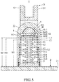
Referring to FIG. 5 , in this embodiment, the connecting hole 222 has a first section (L1), a second section (L2) and a third section (L3). The first and third sections (L1, L3) are respectively proximate to and distal from the shaft hole 221. The second section (L2) interconnects the first and third sections (L1, L3).
Referring to FIGS. 2 to 5 , the moving unit 3 includes first and second moving members 31, 32 that are adapted to cooperatively clamp the door panel 7 therebetween. The first moving member 31 has a U-shaped securing subunit 311 that protrudes toward the second moving member 32. The securing subunit 311 is formed with two securing notches 312 that are spaced apart from each other along the shaft axis (X).
The rotating unit 4 includes a camshaft 41 and two shaft fasteners 42. The camshaft 41 rotatably extends along the shaft axis (X) through the shaft hole 221 of the shaft seat 22, and has two end portions 411 that are transverse to the protruding subunit 311 of the first moving member 31 of the moving unit 3, and that are respectively received in the securing notches 312 of the protruding subunit 311. The shaft fasteners 42 extend in a direction of the connecting axis (Y) from the protruding subunit 311 of the first moving member 31, and respectively engage the two end portions 411 of the camshaft 41 such that the camshaft 41 is connected to the first moving member 31, and that the moving unit 3 is pivotable about the shaft axis (X) relative to the connecting unit 2 for driving the camshaft 41 to rotate about the shaft axis (X).
The resilient unit 5 is disposed in the connecting hole 222, extends along the connecting axis (Y), is connected to the camshaft 41, and has a plurality of coils that surround the connecting axis (Y). Specifically, in this embodiment, the resilient unit 5 includes a first coil spring 51, a second coil spring 52 and a third coil spring 53. The second coil spring 52 is sleeved on the first coil spring 51, and the third coil spring 53 is sleeved on the second coil spring 52. Each of the first, second and third coil springs 51, 52, 53 surrounds the connecting axis (Y) and has a plurality of coils 511, 521, 531. The coils 511, 521, 531 of the first, second and third coil springs 51, 52, 53 constitute the coils of the resilient units 5.
A length (H1) of the first coil spring 51 along the connecting axis (Y) is different from at least one of a length (H2) of the second coil spring 52 along the connecting axis (Y) and a length (H3) of the third coil spring 53 along the connecting axis (Y).
In the present embodiment, the length (H3) of the third coil spring 53 is greater than the length (H1) of the first coil spring 51 and is smaller than the length (H2) of the second coil spring 52. A difference between the length (H2) of the second coil spring 52 and the length (H3) of the third coil spring 53 equals the length of the first section (L1) of the connecting hole 222 along the connecting axis (Y). A difference between the length (H3) of the third coil spring 53 and the length (H1) of the first coil spring 53 equals the length of the second section (L2) of the connecting hole 222 along the connecting axis (Y). The length (H1) of the first coil spring 51 equals the length of the third section (L3) of the connecting hole 222 along the connecting axis (Y). In such a configuration, a quantity of the coils 521, 531 in the second section (L2) is greater than a quantity of the coils 521 in the first section (L1) and is smaller than a quantity of the coils 511, 531, 521 in the third section (L3).
It should be noted that, in other embodiments of the disclosure, the length (H3) of the third coil spring 53 may be equal or smaller than any of the lengths (H1, H2) of the first and second coil springs 51, 52.
The camshaft 41 of the rotating unit 4 is rotatable about the shaft axis (X) between a normal state (as shown in FIG. 5 ), where the coils of the resilient unit 5 are not compressed by the camshaft 41, and an inclined state (as shown in FIGS. 6 and 7 ), where the camshaft 41 is rotated by an angle (θ) from the normal state, and where at least a portion of the coils of the resilient unit 5 is compressed by the camshaft 41 via a cam action between the camshaft 41 and the resilient unit 5. The angle (θ) ranges from 0 to 90 degrees.
The damping unit 6 includes a sliding member 61 and a valve subunit 62. The sliding member 61 is disposed in the connecting hole 222 of the connecting unit 2 and between the resilient unit 5 and the camshaft 41 of the rotating unit 4, abuts against the camshaft 41, and is movable along the connecting axis (Y). The sliding member 61 cooperates with the shaft seat 22 of the connecting unit 2 and the camshaft 41 to define a fluid chamber 610 (see FIGS. 6 and 7 ) which overlaps a portion of the connecting hole 222, and is formed with a fluid hole 611 that spatially interconnects the fluid chamber 610 and the connecting hole 222. The valve subunit 62 is disposed between the sliding member 61 and the resilient unit 5 (i.e., the resilient unit 5 is connected to the camshaft 41 via the sliding member 61 and the valve unit 62), and includes a stationary plate 621 and a valve plate 622. The stationary plate 621 is formed with a valve hole 620 spatially communicating with the fluid hole 611 and the connecting hole 222. The valve plate 622 is disposed between the stationary plate 621 and the sliding member 61. Specifically, the valve plate 622 is movable relative to the stationary plate 621 between an open position (as shown in FIGS. 6 and 7 ) during the movement of the camshaft 41 of the rotating unit 4 from the normal state to the inclined state, and a closed position (as shown in FIG. 5 ) during the movement of the camshaft 41 from the inclined state to the normal state. When the valve plate 622 is at the open position, the valve plate 622 moves away from the valve hole 620, and a center of the valve plate 622 is slightly misaligned from a center of the fluid hole 611 along the connecting axis (Y), thereby permitting the damping fluid inside the sliding member 61 to flow into the fluid chamber 610 via the valve hole 620 and the fluid hole 611. When the valve plate 622 is at the closed position, the valve plate 622 covers the valve hole 620 to block the damping fluid in the fluid chamber 610 from flowing through the valve hole 620.
Referring to FIGS. 3 to 7 , when an external force is applied to the door panel 7 to pivot the moving unit 3 about the shaft axis (X) relative to the connecting unit 2, the first moving member 31 of the moving unit 3 drives the camshaft 41 to rotate about the shaft axis (X) and to drive the sliding member 61 to compress the resilient unit 5. When the resilient unit 5 is being compressed, the damping fluid inside the sliding member 61 is driven to push the valve plate 622 to the open position, such that the damping fluid inside the sliding member 61 is permitted to flow into the fluid chamber 610 via the valve hole 620 and the fluid hole 611 to dampen movements of the sliding member 61 and the camshaft 41.
Initially, when the sliding member 61 is driven by the camshaft 41 to start moving, the sliding member 61 only compresses the second coil spring 52, such that only the resilient force of the second coil spring 52 is exerted on the sliding member 61. As the angle (θ) increases, the sliding member 61 further compresses the third coil springs 53 (see FIG. 6 ). At this point, the combined resilient force of the second and third coil springs 52, 53 is exerted on the sliding member 61. Finally, as the angle (θ) approaches 90 degrees (see FIG. 7 ), the sliding member 61 further compresses the first coil spring 51, and the greater combined resilient force of the first, second and third coil springs 51, 52, 53 is exerted on the sliding member 61. Such configuration of the coil springs 51, 52, 53, combined with the abovementioned damping effect of the damping fluid, produces a multistage damping effect that helps prevent abrupt opening of the door panel 7.
When the external force is eliminated, the sliding member 61 is driven by the resilient force of the resilient unit 5 to move away from the connecting member 21 of the connecting unit 2, thereby driving the camshaft 41 to rotate about the shaft axis (X) in an opposite direction, and resulting in a pivotal movement of the moving unit 3 and the door panel 7 in the same opposite direction.
During the abovementioned process, in which movement of the sliding member 61 results in compression of volume of the fluid chamber 610, the valve plate 622 is driven by the damping fluid in the fluid chamber 610 to move to the closed position to block the valve hole 620. As a result, the damping fluid in the fluid chamber 610 is only permitted to flow back into the connecting hole 222 via a fluid passage (not shown) and, therefore, produces a damping effect which slows down the movement of the sliding member 61.
In addition, by virtue of the abovementioned configuration of the coil springs 51, 52, 53, during the movement of the sliding member 61 away from the connecting member 21, the resilient force is provided by the first, second and third coil springs 51, 52, 53, and then by the second the third coil springs 52, 53, and eventually only by the second coil spring 52, so that the resilient force of the resilient unit 5 decreases in magnitude and rotation of the camshaft 4 is slowed down.
More specifically, as the door panel 7 pivots towards the door frame, the abovementioned movement of the damping fluid and changes of the resilient force of the resilient unit 5 cooperatively slow down the rotation of the camshaft 41 and the pivotal movement of the door panel 7, preventing abrupt closing or slamming of the door panel 7 on the door frame.
Referring to FIGS. 8, 9 and 10 , a second embodiment of the disclosure is similar to the first embodiment, and the difference therebetween is detailed as follows.
The connecting hole 222 of the connecting unit 2 has a first section (L1) and a second section (L2) that are respectively proximate to and distal from the shaft hole 221 of the connecting unit 2 and that are connected to each other.
The resilient unit 5 includes a resilient member 54 that surrounds the connecting axis (Y), and that has a plurality of coils 541, 542 constituting the coils of the resilient unit 5. The coils 541 are disposed in the first section (L1) of the connecting hole 222, and the coils 542 are disposed in the second section (L2) of the connecting hole 222. A pitch (d1) of any adjacent pair of coils 541 is greater than a pitch (d2) of any adjacent pair of coils 542, such that a quantity of coils in the first section (L1) is less than a quantity of coils in the second section (L2). Therefore, when being compressed, the coils 541 have a weaker resilient force than do the coils 542.
Initially, when the sliding member 61 is driven by the camshaft 41 to move, the sliding member 61 compresses the coils 541 of the resilient member 54 and, therefore, the resilient force of the coils 541 is exerted thereon. As the sliding member 61 moves further, the sliding member 61 compresses the coils 541, 542 of the resilient member 54 at the same time, and the combined resilient force of the coils 541, 542 is exerted on the sliding member 61.
Similar to the first embodiment, such a configuration of the coil spring 54 produces a multistage damping effect that helps prevent abrupt opening and closing of the door panel 7.
In the description above, for the purposes of explanation, numerous specific details have been set forth in order to provide a thorough understanding of the embodiments. It will be apparent, however, to one skilled in the art, that one or more other embodiments may be practiced without some of these specific details. It should also be appreciated that reference throughout this specification to “one embodiment,” “an embodiment,” an embodiment with an indication of an ordinal number and so forth means that a particular feature, structure, or characteristic may be included in the practice of the disclosure. It should be further appreciated that in the description, various features are sometimes grouped together in a single embodiment, figure, or description thereof for the purpose of streamlining the disclosure and aiding in the understanding of various inventive aspects, and that one or more features or specific details from one embodiment may be practiced together with one or more features or specific details from another embodiment, where appropriate, in the practice of the disclosure.
While the disclosure has been described in connection with what are considered the exemplary embodiments, it is understood that this disclosure is not limited to the disclosed embodiments but is intended to cover various arrangements included within the spirit and scope of the broadest interpretation so as to encompass all such modifications and equivalent arrangements.
Claims (15)
1. A door hinge comprising:
a connecting unit including
a connecting member, and
a shaft seat that is connected to said connecting member and that is formed with
a shaft hole extending therethrough along a shaft axis, and
a connecting hole extending along a connecting axis that is transverse to the shaft axis, having one end that is spatially communicated with said shaft hole and the other end that is covered by said connecting member, and having a first section and a second section that are respectively proximate to and distal from said shaft hole and that are connected to each other;
a moving unit including first and second moving members that are adapted to cooperatively clamp a door panel therebetween;
a rotating unit including a camshaft that rotatably extends through said shaft hole of said shaft seat, and that is connected to said first moving member; and
a resilient unit disposed in said connecting hole, extending along the connecting axis, connected to said camshaft, and having a plurality of coils that surround the connecting axis;
wherein a quantity of coils in said first section is less than a quantity of coils in said second section, and
wherein said moving unit is pivotable about the shaft axis to drive said camshaft to rotate about the shaft axis against a resilient force of said coils of said resilient unit.
2. The door hinge as claimed in claim 1 , wherein:
said resilient unit includes a first coil spring and a second coil spring, each of said first and second coil springs surrounding the connecting axis and having a plurality of coils, said coils of said first and second coil springs constituting said coils of said resilient units; and
a length of said first coil spring along the connecting axis is different from a length of said second coil spring along the connecting axis.
3. The door hinge as claimed in claim 2 , wherein said camshaft is rotatable about the shaft axis between a normal state, where said coils of said resilient unit are not compressed by said camshaft, and an inclined state, where said camshaft is rotated by an angle from the normal state, and where said coils of said resilient unit are compressed by said camshaft.
4. The door hinge as claimed in claim 3 , wherein:
said connecting hole is adapted for retaining damping fluid therein;
said door hinge further comprises a damping unit including a sliding member that is disposed in said connecting hole and between said resilient unit and said camshaft, that abuts against said camshaft, that is movable along the connecting axis, and that cooperates with said shaft seat and said camshaft to define a fluid chamber which overlaps a portion of said connecting hole;
the damping fluid flows into said fluid chamber when said camshaft is rotated from the normal state to the inclined state; and
the damping fluid flows out of said fluid chamber when said camshaft is rotated from the inclined state to the normal state.
5. The door hinge as claimed in claim 4 , wherein:
said sliding member of said damping unit is formed with a fluid hole that spatially interconnects said fluid chamber and said connecting hole;
said damping unit further includes a valve subunit that is disposed between said sliding member and said resilient unit, and that includes
a stationary plate formed with a valve hole spatially communicating with said fluid hole and said connecting hole, and
a valve plate disposed between said receiving plate and said sliding member, and being movable relative to said stationary plate between an open position during the movement of said camshaft from the normal state to the inclined state, where said valve plate is away from said valve hole to permit the damping fluid inside said sliding member to flow into said fluid chamber via said valve hole, and a closed position during the movement of said camshaft from the inclined state to the normal state, where said valve plate covers said valve hole to block the damping fluid in said fluid chamber from flowing through said valve hole.
6. The door hinge as claimed in claim 1 , wherein:
said resilient unit includes a first coil spring, a second coil spring and a third coil spring, each of said first, second and third coil springs surrounding the connecting axis and having a plurality of coils, said coils of said first, second and third coil springs constituting said coils of said resilient units; and
a length of said first coil spring along the connecting axis is different from at least one of a length of said second coil spring along the connecting axis and a length of said third coil spring along the connecting axis.
7. The door hinge as claimed in claim 6 , wherein:
said connecting hole further has a third section, said second section interconnecting said first section and said third section;
the length of said third coil spring is greater than the length of said first coil spring and is smaller than the length of said second coil spring;
a difference between the length of said second coil spring and the length of said third coil spring equals the length of said first section of said connecting hole along the connecting axis;
a difference between the length of said third coil spring and the length of said first coil spring equals the length of said second section of said connecting hole along the connecting axis; and
the length of said first coil spring equals the length of said third section of said connecting hole along the connecting axis.
8. The door hinge as claimed in claim 6 , wherein said camshaft is rotatable about the shaft axis between a normal state, where said coils of said resilient unit are not compressed by said camshaft, and an inclined state, where said camshaft is rotated by an angle from the normal state, and where said coils of said resilient unit are compressed by said camshaft.
9. The door hinge as claimed in claim 8 , wherein:
said connecting hole is adapted for retaining damping fluid therein;
said door hinge further comprises a damping unit including a sliding member that is disposed in said connecting hole and between said resilient unit and said camshaft, that abuts against said camshaft, that is movable along the connecting axis, and that cooperates with said shaft seat and said camshaft to define a fluid chamber which overlaps a portion of said connecting hole;
the damping fluid flows into said fluid chamber when said camshaft is rotated from the normal state to the inclined state; and
the damping fluid flows out of said fluid chamber when said camshaft is rotated from the inclined state to the normal state.
10. The door hinge as claimed in claim 9 , wherein:
said sliding member of said damping unit is formed with a fluid hole that spatially interconnects said fluid chamber and said connecting hole;
said damping unit further includes a valve subunit that is disposed between said sliding member and said resilient unit, and that includes
a stationary plate formed with a valve hole spatially communicating with said fluid hole and said connecting hole, and
a valve plate disposed between said receiving plate and said sliding member, and being movable relative to said stationary plate between an open position during the movement of said camshaft from the normal state to the inclined state, where said valve plate is away from said valve hole to permit the damping fluid inside said sliding member to flow into said fluid chamber via said valve hole, and a closed position during the movement of said camshaft from the inclined state to the normal state, where said valve plate covers said valve hole to block the damping fluid in said fluid chamber from flowing through said valve hole.
11. The door hinge as claimed in claim 1 , wherein:
said resilient unit includes a resilient member that surrounds the connecting axis, and that has a plurality of coils constituting said coils of said resilient unit; and
a pitch of any adjacent pair of coils of said resilient member in said first section is greater than a pitch of any adjacent pair of coils of said resilient member in said second section.
12. The door hinge as claimed in claim 11 , wherein said camshaft is rotatable about the shaft axis between a normal state, where said coils of said resilient unit are not compressed by said camshaft, and an inclined state, where said camshaft is rotated by an angle from the normal state, and where said coils of said resilient unit are compressed by said camshaft.
13. The door hinge as claimed in claim 12 , wherein:
said connecting hole is adapted for retaining damping fluid therein;
said door hinge further comprises a damping unit including a sliding member that is disposed in said connecting hole and between said resilient unit and said camshaft, that abuts against said camshaft, that is movable along the connecting axis, and that cooperates with said shaft seat and said camshaft to define a fluid chamber which overlaps a portion of said connecting hole;
the damping fluid flows into said fluid chamber when said camshaft is rotated from the normal state to the inclined state; and
the damping fluid flows out of said fluid chamber when said camshaft is rotated from the inclined state to the normal state.
14. The door hinge as claimed in claim 13 , wherein:
said sliding member of said damping unit is formed with a fluid hole that spatially interconnects said fluid chamber and said connecting hole;
said damping unit further includes a valve subunit that is disposed between said sliding member and said resilient unit, and that includes
a stationary plate formed with a valve hole spatially communicating with said fluid hole and said connecting hole, and
a valve plate disposed between said receiving plate and said sliding member, and being movable relative to said stationary plate between an open position during the movement of said camshaft from the normal state to the inclined state, where said valve plate is away from said valve hole to permit the damping fluid inside said sliding member to flow into said fluid chamber via said valve hole, and a closed position during the movement of said camshaft from the inclined state to the normal state, where said valve plate covers said valve hole to block the damping fluid in said fluid chamber from flowing through said valve hole.
15. The door hinge as claimed in claim 1 , wherein:
said first moving member has a securing subunit that protrudes toward said second moving member;
said camshaft has two end portions that are transverse to said protruding subunit; and
said rotating unit further includes two shaft fasteners that extend in a direction of the connecting axis from said protruding subunit, and that respectively engage said two end portions of said camshaft.
Priority Applications (1)
| Application Number | Priority Date | Filing Date | Title |
|---|---|---|---|
| US16/358,849 US10563443B1 (en) | 2019-03-20 | 2019-03-20 | Door hinge |
Applications Claiming Priority (1)
| Application Number | Priority Date | Filing Date | Title |
|---|---|---|---|
| US16/358,849 US10563443B1 (en) | 2019-03-20 | 2019-03-20 | Door hinge |
Publications (1)
| Publication Number | Publication Date |
|---|---|
| US10563443B1 true US10563443B1 (en) | 2020-02-18 |
Family
ID=69528155
Family Applications (1)
| Application Number | Title | Priority Date | Filing Date |
|---|---|---|---|
| US16/358,849 Active US10563443B1 (en) | 2019-03-20 | 2019-03-20 | Door hinge |
Country Status (1)
| Country | Link |
|---|---|
| US (1) | US10563443B1 (en) |
Cited By (1)
| Publication number | Priority date | Publication date | Assignee | Title |
|---|---|---|---|---|
| US11603688B2 (en) * | 2019-05-21 | 2023-03-14 | Bohle Ag | Hinge |
Citations (10)
| Publication number | Priority date | Publication date | Assignee | Title |
|---|---|---|---|---|
| US5867869A (en) * | 1994-10-06 | 1999-02-09 | Chmi | Pressure hinge device for glass door or panel |
| US20100199459A1 (en) * | 2006-05-03 | 2010-08-12 | Luciano Bacchetti | Hinge structure for self-closing doors or the like, particularly glass doors or the like, and assembly incorporating such structure |
| TWM412227U (en) | 2010-11-01 | 2011-09-21 | E Tai Entpr Co Ltd | Spring damping hinge and control device thereof |
| US20120216370A1 (en) * | 2009-08-18 | 2012-08-30 | Chung Chow | Damped door hinge |
| US20120279015A1 (en) * | 2011-05-06 | 2012-11-08 | E Tai Enterprise Co., Ltd. | Damped hinge and control device thereof |
| US20140068893A1 (en) * | 2012-09-07 | 2014-03-13 | E Tai Enterprise Co., Ltd. | Door damping apparatus and manufacturing method thereof |
| US8720005B2 (en) * | 2011-12-21 | 2014-05-13 | Gang Gwo Industrial Co., Ltd. | Hydraulic hinge for a glass door |
| DE202014103333U1 (en) * | 2014-07-18 | 2014-08-29 | E Tai Enterprise Co., Ltd. | Hinge with spring damping |
| GB2484527B (en) * | 2010-10-14 | 2015-05-20 | Chung Chow | Hinge having self centering means |
| US10400495B1 (en) * | 2018-07-10 | 2019-09-03 | Sun-Q Door Controls Limited | Automatic return device for glass door |
-
2019
- 2019-03-20 US US16/358,849 patent/US10563443B1/en active Active
Patent Citations (10)
| Publication number | Priority date | Publication date | Assignee | Title |
|---|---|---|---|---|
| US5867869A (en) * | 1994-10-06 | 1999-02-09 | Chmi | Pressure hinge device for glass door or panel |
| US20100199459A1 (en) * | 2006-05-03 | 2010-08-12 | Luciano Bacchetti | Hinge structure for self-closing doors or the like, particularly glass doors or the like, and assembly incorporating such structure |
| US20120216370A1 (en) * | 2009-08-18 | 2012-08-30 | Chung Chow | Damped door hinge |
| GB2484527B (en) * | 2010-10-14 | 2015-05-20 | Chung Chow | Hinge having self centering means |
| TWM412227U (en) | 2010-11-01 | 2011-09-21 | E Tai Entpr Co Ltd | Spring damping hinge and control device thereof |
| US20120279015A1 (en) * | 2011-05-06 | 2012-11-08 | E Tai Enterprise Co., Ltd. | Damped hinge and control device thereof |
| US8720005B2 (en) * | 2011-12-21 | 2014-05-13 | Gang Gwo Industrial Co., Ltd. | Hydraulic hinge for a glass door |
| US20140068893A1 (en) * | 2012-09-07 | 2014-03-13 | E Tai Enterprise Co., Ltd. | Door damping apparatus and manufacturing method thereof |
| DE202014103333U1 (en) * | 2014-07-18 | 2014-08-29 | E Tai Enterprise Co., Ltd. | Hinge with spring damping |
| US10400495B1 (en) * | 2018-07-10 | 2019-09-03 | Sun-Q Door Controls Limited | Automatic return device for glass door |
Cited By (1)
| Publication number | Priority date | Publication date | Assignee | Title |
|---|---|---|---|---|
| US11603688B2 (en) * | 2019-05-21 | 2023-03-14 | Bohle Ag | Hinge |
Similar Documents
| Publication | Publication Date | Title |
|---|---|---|
| US7107649B2 (en) | Hinge device | |
| US6154924A (en) | Door closer unit | |
| US5901415A (en) | Dual pivot hinge assembly | |
| US20030097732A1 (en) | Hinge device | |
| US6630878B2 (en) | Magnetic rotating apparatus | |
| US10563443B1 (en) | Door hinge | |
| CN107965223B (en) | Buffer hinge device | |
| US20100101053A1 (en) | Hinge assembly | |
| WO2024060629A1 (en) | Vehicle door linkage hinge mechanism and vehicle | |
| JPH07286472A (en) | Damper hinge | |
| WO1995014842A1 (en) | Friction hinge with detent | |
| US10443284B2 (en) | Friction hinge with restricted motion in one direction | |
| CN114278665A (en) | Rotating shaft assembly and electronic equipment | |
| CN109914955B (en) | Two-way hinge that opens door of pet nest | |
| US3702015A (en) | Hold open assembly for checking floor hinge | |
| JP2010248800A (en) | Stay for cabinet, and cabinet using the same | |
| US3518715A (en) | Automatic hinge-mounted door closer | |
| TWI674352B (en) | Hinge for glass doors | |
| WO2023284042A1 (en) | Buffering, secure, and automatic door closing hinge | |
| CN2504364Y (en) | Spring hinge for two-way door | |
| JP3039413U (en) | Damper hinge | |
| CN216210743U (en) | Flexible hinge assembly, display device using same and intelligent terminal | |
| CN210239419U (en) | Automobile door hinge | |
| KR101006179B1 (en) | Portable terminal | |
| CN218147431U (en) | Washing machine |
Legal Events
| Date | Code | Title | Description |
|---|---|---|---|
| FEPP | Fee payment procedure |
Free format text: ENTITY STATUS SET TO UNDISCOUNTED (ORIGINAL EVENT CODE: BIG.); ENTITY STATUS OF PATENT OWNER: SMALL ENTITY |
|
| FEPP | Fee payment procedure |
Free format text: ENTITY STATUS SET TO SMALL (ORIGINAL EVENT CODE: SMAL); ENTITY STATUS OF PATENT OWNER: SMALL ENTITY |
|
| STCF | Information on status: patent grant |
Free format text: PATENTED CASE |
|
| MAFP | Maintenance fee payment |
Free format text: PAYMENT OF MAINTENANCE FEE, 4TH YR, SMALL ENTITY (ORIGINAL EVENT CODE: M2551); ENTITY STATUS OF PATENT OWNER: SMALL ENTITY Year of fee payment: 4 |