EP3736643A1 - Watertight watch case - Google Patents
Watertight watch case Download PDFInfo
- Publication number
- EP3736643A1 EP3736643A1 EP19173326.0A EP19173326A EP3736643A1 EP 3736643 A1 EP3736643 A1 EP 3736643A1 EP 19173326 A EP19173326 A EP 19173326A EP 3736643 A1 EP3736643 A1 EP 3736643A1
- Authority
- EP
- European Patent Office
- Prior art keywords
- crystal
- watch case
- annular
- seal
- peripheral surface
- Prior art date
- Legal status (The legal status is an assumption and is not a legal conclusion. Google has not performed a legal analysis and makes no representation as to the accuracy of the status listed.)
- Pending
Links
Images


Classifications
-
- G—PHYSICS
- G04—HOROLOGY
- G04B—MECHANICALLY-DRIVEN CLOCKS OR WATCHES; MECHANICAL PARTS OF CLOCKS OR WATCHES IN GENERAL; TIME PIECES USING THE POSITION OF THE SUN, MOON OR STARS
- G04B39/00—Watch crystals; Fastening or sealing of crystals; Clock glasses
- G04B39/02—Sealing crystals or glasses
-
- G—PHYSICS
- G04—HOROLOGY
- G04B—MECHANICALLY-DRIVEN CLOCKS OR WATCHES; MECHANICAL PARTS OF CLOCKS OR WATCHES IN GENERAL; TIME PIECES USING THE POSITION OF THE SUN, MOON OR STARS
- G04B39/00—Watch crystals; Fastening or sealing of crystals; Clock glasses
-
- G—PHYSICS
- G04—HOROLOGY
- G04B—MECHANICALLY-DRIVEN CLOCKS OR WATCHES; MECHANICAL PARTS OF CLOCKS OR WATCHES IN GENERAL; TIME PIECES USING THE POSITION OF THE SUN, MOON OR STARS
- G04B37/00—Cases
- G04B37/0008—Cases for pocket watches and wrist watches
-
- G—PHYSICS
- G04—HOROLOGY
- G04B—MECHANICALLY-DRIVEN CLOCKS OR WATCHES; MECHANICAL PARTS OF CLOCKS OR WATCHES IN GENERAL; TIME PIECES USING THE POSITION OF THE SUN, MOON OR STARS
- G04B37/00—Cases
- G04B37/08—Hermetic sealing of openings, joints, passages or slits
-
- G—PHYSICS
- G04—HOROLOGY
- G04B—MECHANICALLY-DRIVEN CLOCKS OR WATCHES; MECHANICAL PARTS OF CLOCKS OR WATCHES IN GENERAL; TIME PIECES USING THE POSITION OF THE SUN, MOON OR STARS
- G04B37/00—Cases
- G04B37/08—Hermetic sealing of openings, joints, passages or slits
- G04B37/084—Complete encasings for wrist or pocket watches without means for hermetic sealing of winding stem or crown
-
- G—PHYSICS
- G04—HOROLOGY
- G04B—MECHANICALLY-DRIVEN CLOCKS OR WATCHES; MECHANICAL PARTS OF CLOCKS OR WATCHES IN GENERAL; TIME PIECES USING THE POSITION OF THE SUN, MOON OR STARS
- G04B37/00—Cases
- G04B37/08—Hermetic sealing of openings, joints, passages or slits
- G04B37/088—Means affording hermetic sealing inside the case, e.g. protective case for the clockwork against dust, the escapement being in a hermetically sealed case
-
- G—PHYSICS
- G04—HOROLOGY
- G04B—MECHANICALLY-DRIVEN CLOCKS OR WATCHES; MECHANICAL PARTS OF CLOCKS OR WATCHES IN GENERAL; TIME PIECES USING THE POSITION OF THE SUN, MOON OR STARS
- G04B39/00—Watch crystals; Fastening or sealing of crystals; Clock glasses
- G04B39/02—Sealing crystals or glasses
- G04B39/025—Sealing crystals or glasses without special sealing parts
-
- G—PHYSICS
- G04—HOROLOGY
- G04B—MECHANICALLY-DRIVEN CLOCKS OR WATCHES; MECHANICAL PARTS OF CLOCKS OR WATCHES IN GENERAL; TIME PIECES USING THE POSITION OF THE SUN, MOON OR STARS
- G04B45/00—Time pieces of which the indicating means or cases provoke special effects, e.g. aesthetic effects
- G04B45/0084—Pictures or inscriptions on the case or parts thereof, attaching complete pictures
Definitions
- the present invention relates to a waterproof watch case, in particular for a diving watch.
- the watch case which comprises a watch movement or a time-based watch module, must be closed in a well-sealed manner.
- the watch case comprises a case back fixed in a sealed manner to a first side of a middle part and a crystal fixed to a second opposite side of the middle part. Sealing gaskets are provided for the assembly of the back, the caseband and the watch crystal.
- a member for controlling or adjusting the functions of the watch is also mounted in a sealed manner through the middle part of the case in the rest position.
- watch cases are not configured or assembled to withstand high water pressures, for example during a dive, given that the pressure inside the watch case is close to atmospheric pressure.
- Simple gaskets of traditional watches are not sufficient to guarantee a good watertightness of the case when diving to very great depths underwater.
- the watch case consists of a crystal fixed on an upper side to a caseband-bezel and a caseback fixed to the caseband by screwing it to an internal thread of the caseband.
- the crystal is fixed to the middle part by an annular seal in the shape of a toric and rests on a middle edge.
- a seal is also provided between an outer edge of the back and a lower surface of the caseband.
- a strong metal cup is still provided to bear against an interior surface of the back and against an interior edge of the caseband.
- this does not make it possible to guarantee good sealing of the case during diving to very great depths underwater, which constitutes a drawback.
- the patent CH 372 606 describes a waterproof watch case, which has a central part or middle part surrounding a back and closed by a crystal. A threaded ring bears against an inclined outer surface of the caseback to retain it, and is screwed to a fastening portion connected to the caseband. With such an arrangement presented, this does not make it possible to guarantee good sealing of the box during diving to very great depths underwater, which constitutes a drawback.
- the main aim of the invention is therefore to overcome the drawbacks of the state of the art described above by providing a watertight watch case suitable for withstanding high water pressure for diving at great depths. under water.
- the present invention relates to a waterproof watch case, which comprises the features of independent claim 1.
- An advantage of the watertight watch case is that the crystal is attached to the middle part by means of a one-piece metal seal and with inclined contact surfaces of the middle part and the crystal.
- the metal fixing gasket has a shape complementary to fixing surfaces before the operation of fixing the crystal to the caseband.
- conical bearing surfaces are provided on the crystal and the middle part, or even on the back mounted on an opposite side of the middle part. In this way, pressure forces on the crystal and the back are transmitted to the caseband via conical bearing surfaces and via the one-piece metal seal.
- the fixing of the crystal to the middle part by means of the fixing seal can be done in particular by hot forming. This makes it possible to avoid stress concentrations, to achieve good resistance of the crystal and to achieve very good sealing of the watch case.
- the heated amorphous metal gasket is in a softened state so as to be well applied on the contact surface of the crystal and the contact surface of the middle part, filling everything in. interstice of the surface condition of each contact surface.
- the amorphous metal gasket serves as a stress interface between the caseband and the crystal as the thermal expansion coefficient of the caseband, for example in titanium, is greater than that of the sapphire crystal, for example.
- the figures 1a and 1b show an embodiment of a watch case 1, which can be used for a diving watch.
- the watch case 1 essentially comprises a crystal 3, which can be made of sapphire or mineral glass, fixed on an upper side of a caseband 2, and possibly a back 4 mounted on a lower side of the caseband 2.
- a bezel 7 can also be mounted on the upper side of the middle part 2.
- a movement or watch module 10 is arranged in the watch case 1 in a casing circle 8, and at least one control member, not shown, can be mounted in a sealed manner in the rest position on or through the middle 2 for setting the time, date or other functions of the diving watch.
- the solid back 4 may include an annular edge 14 with internal thread to be screwed onto a thread 26 on the lower side of the caseband 2.
- a surface of annular support 24 of the back 4 comes into contact with an annular interior surface 32 of the middle part 2 of a shape complementary to the support surface 24 during the mounting of the back 4 on the middle part 2.
- the support surfaces 24 and interior 32 are inclined at a determined angle with respect to an axis perpendicular to a watch case plane 1.
- the surfaces 24, 32 are of conical shape and inclined towards the inside of watch case 1 at an angle determined from a central axis of watch case 1. This means that the top of each cone shape is towards the inside of watch case 1.
- the lower side of the caseband 2 further comprises an annular groove 16 housing a gasket O-ring seal 6 in contact with the bearing surface 24 when mounting the back 4 on the middle 2.
- the angle can be of the order of 60 ° ⁇ 5 ° with respect to the central axis. This makes it possible to have a good distribution of the stresses between the bottom 4 and the middle 2 due to the pressure of the water during diving at great depths underwater.
- the crystal 3 comprises an annular peripheral surface 13 to be fixed by means of a one-piece metal seal 5, 5 'for fixing to an annular inner surface 12 on the upper side of the middle part 2.
- the annular inner surface 12 is preferably of complementary shape to the annular peripheral surface 13.
- the seal 5, 5 ', as an interface between the middle part 2 and the crystal 3, can also be produced before the fixing operation with a complementary shape to the contact surfaces of the crystal 3 on the caseband 2.
- the annular peripheral surface 13 of the crystal 3 is inclined at a defined angle smaller than 90 ° with respect to an axis perpendicular to a watch case plane 1.
- the inner surface ring 12 is inclined generally towards the inside of the box of watch 1 at the same angle as the annular peripheral surface 13 with respect to a central axis.
- the middle part 2 is generally cylindrical in shape
- the peripheral inner surface 13 and the annular inner surface 12 are conical in shape and inclined at a defined angle towards the inside of the watch case.
- the defined angle of inclination of surfaces 12 and 13 can be of the order of 43 ° ⁇ 5 ° from to the central axis. This makes it possible to have a good distribution of the stresses between the crystal 3 and the caseband 2 due to the pressure of the water during diving at great depths underwater.
- the difference in water pressure relative to the pressure inside the watch case 1 tends to close any gap remaining between the surfaces 12, 13 in contact and the seal 5, 5 ′ for fixing thanks to the The inclination of the contact surfaces towards the inside of the watch case 1. This guarantees a good seal and resistance to high pressures.
- the one-piece metal fixing seal 5, 5 ' is made of amorphous metal or metal glass or amorphous metal alloy. It can include a first part 5 and a second part 5 '.
- the fixing gasket 5, 5 ′ is of annular shape for the hermetic closing of the crystal 3 on the middle part 2.
- the first part 5 of the gasket is of conical shape, while the second part 5 'is cylindrical.
- the length of the first part 5 in cross section can be of the order of 5 mm, while the height of the second part of the seal 5, 5 ′ can be of the order of 2.5 mm.
- the thickness of the seal can be of the order of 0.65 mm.
- the one-piece metal seal 5, 5 ′ for fixing the annular shape is made of an amorphous metal alloy so as to fix the crystal 3 to the middle 2, for example by hot deformation.
- fixing the crystal 3 to the caseband 2 one seeks to completely fill the space between the crystal 3 and the caseband 2.
- the seal with pressure of the crystal 3 on the caseband 2
- the The heat-softened amorphous metal seal completely matches the surface finish of the crystal 3 and the caseband 2, which guarantees a good hermetic seal.
- the metal also compensates for a possible defect of angles between the conical surface of the crystal 3 and the conical surface of the middle part 2, and thus makes it possible to ensure a perfect contact between the crystal 3 and the middle part 2, which reduces high stress concentrations during pressurization.
- This is very important because the crystal 3 is generally made of a fragile material, such as sapphire or mineral glass. Thus, a very localized contact of the crystal 3 on the middle part 2 risks causing a break when pressurizing under water.
- the amorphous metal gasket 5, 5 ′ serves as an interface between the middle part 2 and the crystal 3.
- this seal also serves to accumulate stresses during the cooling operation. This is important because the thermal expansion coefficient of the titanium middle part 2 is greater than the contact surface of the sapphire crystal 3.
- the alloy of amorphous metals can be mainly composed of zirconium, which makes it possible to form the seal at a temperature above 350 ° C, that is to say above the glass transition temperature. of the alloy.
- the zirconium-based amorphous metal alloy can be composed of Zr (52.5%), Cu (17.6%), Ni (14.9%), Al (10%) and Ti (5%).
- the zirconium-based amorphous metal alloy can also include Zr (58.5%), Cu (15.6%), Ni (12.8%), Al (10.3%) and Nb (2.8%).
- the zirconium-based amorphous metal alloy can also include Zr (44%), Ti (11%), Cu (9.8%), Ni (10.2%) and Be (25%), or finally Zr (58%) , Cu (22%), Fe (8%) and Al (12%).
- the alloy of amorphous metals may be mainly composed of platinum (Pt), which makes it possible to form the seal at a temperature above 230 ° C.
- the platinum-based amorphous metal alloy can include Pt (57.5%), Cu (14.7%), Ni (5.3%) and P (22.5%). Provision may also be made to produce the one-piece metal seal 5, 5 'from an alloy of amorphous metals based mainly on palladium (Pd, which makes it possible to form the seal at a temperature above 300 ° C.
- a titanium-based amorphous metal alloy can include Ti (41.5%), Zr (10%), Cu (35%), Pd (11%) and Sn (2.5%).
- An alloy of amorphous metals based on palladium may include Pd (43%), Cu (27%), Ni (10%) and P (20%), or Pd (77%), Cu (6%) and Si ( 16.5%), or finally Pd (79%), Cu (6%), Si (10%) and P (5%).
- a nickel-based amorphous metal alloy can include Ni (53%), Nb (20%), Ti (10%), Zr (8%), Co (6%) and Cu (3%), or Ni (67%), Cr (6%), Fe (4%), Si (7%), C (0.25%) and B (15.75%), or finally Ni (60 %), Pd (20%), P (17%) and B (3%).
- An iron-based amorphous metal alloy can include Fe (45%), Cr (20%), Mo (14%), C (15%) and B (6%), or Fe (56%), Co ( 7%), Ni (7%), Zr (8%), Nb (2%) and B (20%).
- a gold-based amorphous metal alloy can include Au (49%), Ag (5%), Pd (2.3%), Cu (26.9%) and Si (16.3%).
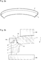
- annular fastening joint with the first part 5 of conical shape and the second part 5 'of cylindrical shape is shown in a three-dimensional partial sectional view at the bottom. figure 2a .
- This form of two-part seal 5, 5 ' is used for fixing the crystal 3 to the middle 2 as shown in figures 2b and 2c .
- the gasket 5, 5 ' is first of all placed on the upper side of the caseband 2.
- the first part 5 of the gasket is in contact with the annular inner surface 12, while the second part 5' is close to the wall annular interior 22 of the middle 2.
- the crystal 3 is mounted on the seal 5, 5 '.
- the annular peripheral surface 13 of the lens 3 is in contact with the first part 5 of the seal, while the annular outer wall 23 ice 3 above the annular peripheral surface 13 is close to the second part 5 'of the seal.
- the seal 5, 5 ' is placed between the middle part 2 and the crystal 3.
- an anti-overflow tool MC is placed on the upper side of the caseband 2 and in contact with the annular outer wall 23 of the crystal 3.
- This anti-overflow tool MC is used to prevent the amorphous metal alloy of the seal from coming out of the upper side of the caseband 2.
- Another anti-overflow tool not shown in underside of the inner side of the watch case to prevent the amorphous metal alloy of the gasket from coming out of the underside.
- a high tool MH presses the crystal 3 towards the case 2, while a low tool MB holds the lower side of the case 2 in support.
- a pressure of the order of 10,000 to 80,000 N is applied to the crystal 3 on the caseband 2 at a temperature of the order of 480 ° C. for a period of 30 - 250 seconds.
- the pressure exerted by the sapphire 3 on the part 5 of the seal causes the material contained in the part 5 of the seal to flow towards the part 5 'as well as downwards.
- the consequences are a downward displacement of the glass 3 and a thinning of the part 5 of the seal until the seal completely fills the space between the caseband 2, the anti-overflow tool MC, the interior anti-overflow tool and ice 3.
- the amorphous metal gasket will, during its flow, mold all the details of surfaces 12, 13, 22 and 23.
- the dimensions of the caseband 2, of the seal 5, 5 'and of the crystal 3 will want to decrease proportionally to their respective coefficients of expansion ⁇ .
- ⁇ 8.5 to 11 ppm for titanium, 12 to 18 ppm for stainless steel; 12 to 16 for gold
- amorphous metals in particular their very high elastic limit ⁇ e (eg: 1700 MPa for a Zr base; 1550 MPa for a Pd base; 1350 MPa for a Pt base) coupled with an elastic deformation Very high ⁇ e (1.5 to 2% for all amorphous metals), make it possible to avoid plasticization of the seal 5, 5 ′ in its zone of contact with the glass 3 during stress at very high pressures.
- Caseband 2 whose mechanical properties (e.g.
- the fixing of the crystal 3 to the caseband 2 by means of the seal 5, 5 ' is carried out at a temperature of the order of 380 ° C. by applying a pressure of approximately 10,000 - 80,000 N for 30 - 250 seconds.
- the fixing of the crystal 3 to the caseband 2 by means of the seal 5, 5 ' is carried out at a temperature of the order of 280 ° C by applying a pressure of approximately 10,000 - 80,000 N for 30 - 250 seconds.
- Another way of reducing the stresses in the glass 3 after the assembly process, as described above, is to partially or totally crystallize the seal 5, 5 'of amorphous metal.
- crystallization generates a reduction in the volume of the amorphous metal and therefore of the seal 5, 5 ', which slightly detaches the middle-seal and seal-glass contact surfaces.
- the differential retraction of the caseband 2 must first compensate for the vacuum left by the crystallization of the amorphous metal before starting to tighten on the crystal 3.
- the residual stresses in the sapphire are less compared to a gasket. 100% amorphous.
- the crystallization of the seal 5, 5 ′ can take place by maintaining the assembly at a temperature for a long time after the forming phase. For example, for the case of a zirconium-based alloy, holding for 5 min at 480 ° C. can generate crystallization of the seal. It is also possible to increase the temperature from 20 ° C to 100 ° C after the creep phase in order to accelerate crystallization or to modify its nature (different crystalline phases). It is also possible to decrease the temperature after the creep phase in order to obtain a slower and finer crystallization.
- the figure 2c shows the result of attaching crystal 3 to caseband 2 after removing the tools used for it.
- a bezel 7 covers the upper side of the middle part 2.
- the first part 5 of the gasket fixedly connects the annular peripheral surface 13 of the crystal 3 to the annular inner surface 12 of the middle part 2.
- the second part 5 'of the gasket fixedly connects the annular inner wall 22 of the middle part 2 and the annular outer wall 23 of the crystal 3. Normally the first part 5 of the seal extends below the level of the connection between the bottom of the crystal 3 and the caseband 2, which therefore does not include the inner spout presented to figures 2b and 2c .
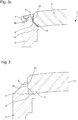
- the figure 3 shows a partial detail section of a variant of the attachment of the crystal 3 to the caseband 2.
- the crystal 3 comprises an annular peripheral surface 13 to be fixed by means of a one-piece metal seal 5, 5 'for fixing on an annular inner surface 12 on the upper side of the middle part 2.
- the middle part 2 is generally cylindrical in shape
- the peripheral inner surface 13 of the crystal 3 is conical in shape
- the annular inner surface 12 of the middle part 2 is in the plane of the watch case 1 in the form of a portion of a disc.
- the first part 5 of the seal is between the peripheral inner surface 13 and the annular inner surface 12, while the second part 5 'of the seal is between the annular inner wall 22 of the caseband 2 and the annular outer wall 23 of the crystal 3 .
- the figure 4 schematically shows a top view of an embodiment of a watch case 1.
- the watch case 1 comprises the middle part 2, the crystal 3, a bezel 7 and a control member 9 in the form of a stem-crown passing through the middle part 2.
- the stem-crown comprises a conical surface, not shown in contact with a conical inner surface of the middle part 2 in the rest position to ensure tightness and resistance to water pressure in diving.
- An inscription 103 of a word or of a number or of drawings is made at the connection of the annular peripheral surface 13 of the glass 3 on the first part of the fixing joint.
- the inscription 103 may also be provided to have a contact surface of the glass 3 structured and / or with a decorative layer deposited on its surface.
- This structuring and / or deposit 63 can be placed on the annular peripheral surface 13 of the crystal 3. It can also be envisaged to write a or several words, or numbers or patterns by etching the deposit 63 by means of a laser beam L coming from a laser device 50.
- the deposit 63 may be of a different color from the first part of the fixing joint. Therefore after the engraving of the inscription 103 on the deposit 63, the annular peripheral surface 13 of the crystal 3 can be placed or fixed on the first part of the fixing joint, which is of a different color than the deposit 63 .
- the watch case by its middle part may have a general shape different from a cylinder.
Abstract
La boîte de montre (1) étanche à l'eau d'une montre de plongée, comprend au moins un fond (4) monté sur un côté inférieur d'une carrure (2), et une glace (3) montée sur un côté supérieur de la carrure. La glace (3) comprend une surface périphérique annulaire (13) pour être fixée par l'intermédiaire d'un joint en métal amorphe (5, 5') sur une surface intérieure annulaire (12) de forme complémentaire du côté supérieur de la carrure. La surface périphérique annulaire de la glace est inclinée vers l'intérieur de la boîte de montre d'un angle défini plus petit que 90° par rapport à un axe central perpendiculaire à un plan de boîte de montre pour répartir des contraintes entre la glace et la carrure dues à la pression de l'eau lors d'une plongée. La surface périphérique annulaire et la surface intérieure annulaire sont de forme conique.

Description
La présente invention concerne une boîte de montre étanche notamment pour une montre de plongée.The present invention relates to a waterproof watch case, in particular for a diving watch.
Pour prévoir l'utilisation d'une montre mécanique ou électronique sous l'eau, la boîte de montre, qui comprend un mouvement horloger ou un module horloger à base de temps, doit être fermée de manière bien étanche. Pour ce faire, la boîte de montre comprend un fond fixé de manière étanche à un premier côté d'une carrure et une glace fixée à un second côté opposé de la carrure. Des garnitures d'étanchéité sont prévues à l'assemblage du fond, de la carrure et de la glace de montre. Un organe de contrôle ou réglage de fonctions de la montre est monté également de manière étanche à travers la carrure de la boîte en position de repos.In order to provide for the use of a mechanical or electronic watch underwater, the watch case, which comprises a watch movement or a time-based watch module, must be closed in a well-sealed manner. To do this, the watch case comprises a case back fixed in a sealed manner to a first side of a middle part and a crystal fixed to a second opposite side of the middle part. Sealing gaskets are provided for the assembly of the back, the caseband and the watch crystal. A member for controlling or adjusting the functions of the watch is also mounted in a sealed manner through the middle part of the case in the rest position.
Généralement des boîtes de montre ne sont pas configurées ou assemblées pour supporter de fortes pressions d'eau par exemple lors d'une plongée étant donné que la pression à l'intérieur de la boîte de montre est proche de la pression atmosphérique. De simples garnitures d'étanchéité de montres traditionnelles ne suffisent pas pour garantir une bonne étanchéité à l'eau de la boîte lors d'une plongée à de très grandes profondeurs sous l'eau.Generally, watch cases are not configured or assembled to withstand high water pressures, for example during a dive, given that the pressure inside the watch case is close to atmospheric pressure. Simple gaskets of traditional watches are not sufficient to guarantee a good watertightness of the case when diving to very great depths underwater.
On peut citer la demande de brevet
Le brevet
L'invention a donc pour but principal de pallier les inconvénients de l'état de la technique décrit ci-dessus en proposant une boîte de montre étanche à l'eau adaptée pour supporter les fortes pression d'eau pour une plongée à de grandes profondeurs sous l'eau.The main aim of the invention is therefore to overcome the drawbacks of the state of the art described above by providing a watertight watch case suitable for withstanding high water pressure for diving at great depths. under water.
A cet effet, la présente invention concerne une boîte de montre étanche à l'eau, qui comprend les caractéristiques de la revendication indépendante 1.To this end, the present invention relates to a waterproof watch case, which comprises the features of
Des formes particulières d'exécution d'une boîte de montre étanche à l'eau sont définies dans les revendications dépendantes 2 à 16.Particular embodiments of a waterproof watch case are defined in
Un avantage de la boîte de montre étanche à l'eau réside dans le fait que la glace est fixée à la carrure par l'intermédiaire d'un joint métallique monobloc et avec des surfaces de contact inclinées de la carrure et de la glace. Le joint métallique de fixation a une forme complémentaire aux surfaces de fixation avant l'opération de fixation de la glace à la carrure. Dans le cas d'une carrure de forme générale cylindrique, des surfaces d'appui coniques sont prévues sur la glace et la carrure, voire aussi sur le fond monté d'un côté opposé de la carrure. De cette manière, des efforts de pression sur la glace et le fond sont transmis à la carrure via des surfaces d'appui coniques et par l'intermédiaire du joint métallique monobloc.An advantage of the watertight watch case is that the crystal is attached to the middle part by means of a one-piece metal seal and with inclined contact surfaces of the middle part and the crystal. The metal fixing gasket has a shape complementary to fixing surfaces before the operation of fixing the crystal to the caseband. In the case of a middle part of generally cylindrical shape, conical bearing surfaces are provided on the crystal and the middle part, or even on the back mounted on an opposite side of the middle part. In this way, pressure forces on the crystal and the back are transmitted to the caseband via conical bearing surfaces and via the one-piece metal seal.
Avantageusement dans le cas d'un joint monobloc en métal amorphe, la fixation de la glace sur la carrure par l'intermédiaire du joint de fixation peut être fait notamment par un formage à chaud. Cela permet d'éviter les concentrations de contraintes, de réaliser une bonne tenue de la glace et de réaliser une très bonne étanchéité de la boîte de montre.Advantageously, in the case of a one-piece amorphous metal seal, the fixing of the crystal to the middle part by means of the fixing seal can be done in particular by hot forming. This makes it possible to avoid stress concentrations, to achieve good resistance of the crystal and to achieve very good sealing of the watch case.
Avantageusement lors de l'opération de fixation de la glace sur la carrure, le joint en métal amorphe chauffé est dans un état ramolli pour bien s'appliquer sur la surface de contact de la glace et la surface de contact de la carrure en comblant tout interstice de l'état de surface de chaque surface de contact. De plus, lors du refroidissement de la glace fixée à la carrure, le joint en métal amorphe sert d'interface de contraintes entre la carrure et la glace comme le coefficient de dilation thermique de la carrure, par exemple en titane, est plus grand que celui de la glace par exemple en saphir.Advantageously, during the operation of fixing the crystal on the middle part, the heated amorphous metal gasket is in a softened state so as to be well applied on the contact surface of the crystal and the contact surface of the middle part, filling everything in. interstice of the surface condition of each contact surface. In addition, when cooling the crystal attached to the caseband, the amorphous metal gasket serves as a stress interface between the caseband and the crystal as the thermal expansion coefficient of the caseband, for example in titanium, is greater than that of the sapphire crystal, for example.
Les buts, avantages et caractéristiques d'une boîte de montre étanche à l'eau apparaîtront mieux dans la description suivante de manière non limitative en regard des dessins sur lesquels :
- les
figures 1a et 1b représentent de manière simplifiée une coupe transversale d'une forme d'exécution d'une montre avec une boîte étanche à l'eau selon l'invention, et une coupe partielle de détail de la fixation de la glace à la carrure selon l'invention, - les
figures 2a à 2c représentent un joint de fixation en vue partiellement en coupe tridimensionnelle et différentes étapes de la fixation de la glace à la carrure par l'intermédiaire du joint de fixation de la boîte de montre selon l'invention, - la
figure 3 représente une coupe partielle de détail d'une variante de la fixation de la glace à la carrure selon l'invention, - la
figure 4 représente schématiquement une vue de dessus d'une forme d'exécution d'une boîte de montre selon l'invention, et - les
figures 5a et 5b représentent une glace avec un revêtement métallique susceptible d'être gravé par un laser pour la réalisation d'une inscription sur la surface de fixation de la glace sur la carrure, et une portion du revêtement métallique sur la glace avec l'inscription selon l'invention.
- the
figures 1a and 1b show in a simplified manner a cross section of an embodiment of a watch with a waterproof case according to the invention, and a partial detail section of the attachment of the crystal to the caseband according to the invention , - the
figures 2a to 2c show a fixing joint in a view partially in three-dimensional section and different stages of fixing the crystal to the middle part by means of the fixing joint of the watch case according to the invention, - the
figure 3 shows a partial detail section of a variant of the attachment of the crystal to the middle part according to the invention, - the
figure 4 schematically represents a top view of an embodiment of a watch case according to the invention, and - the
figures 5a and 5b represent a crystal with a metallic coating capable of being engraved by a laser to produce an inscription on the fixing surface of the crystal on the caseband, and a portion of the metallic coating on the crystal with the inscription according to invention.
Dans la description suivante, tous les composants d'une boîte de montre étanche à l'eau notamment d'une montre de plongée, qui sont bien connus d'un homme du métier dans ce domaine technique ne sont relatés que de manière simplifiée.In the following description, all the components of a watertight watch case, in particular a diving watch, which are well known to a person skilled in the art in this technical field are only described in a simplified manner.
Les
Dans le cas où il est prévu un fond 4 de la boîte de montre 1, le fond 4 massif peut comprendre un bord annulaire 14 à taraudage intérieur pour être vissé sur un taraudage 26 sur le côté inférieur de la carrure 2. Une surface d'appui annulaire 24 du fond 4 vient en contact d'une surface intérieure annulaire 32 de la carrure 2 de forme complémentaire à la surface d'appui 24 lors du montage du fond 4 sur la carrure 2. Les surfaces d'appui 24 et intérieure 32 sont inclinées d'un angle déterminé par rapport à un axe perpendiculaire à un plan de boîte de montre 1. Dans le cas d'une carrure de forme générale cylindrique, les surfaces 24, 32 sont de forme conique et inclinées vers l'intérieur de la boîte de montre 1 d'un angle déterminé par rapport à un axe central de la boîte de montre 1. Cela signifie que le sommet de chaque forme de cône est en direction de l'intérieur de la boîte de montre 1. Le côté inférieur de la carrure 2 comprend encore une rainure annulaire 16 logeant une garniture d'étanchéité 6 de forme torique en contact de la surface d'appui 24 lors du montage du fond 4 sur la carrure 2. Pour une carrure 2 et un fond 4 réalisés dans un matériau, tel que le titane, l'angle peut être de l'ordre de 60° ± 5° par rapport à l'axe central. Ceci permet d'avoir une bonne répartition des contraintes entre le fond 4 et la carrure 2 dues à la pression de l'eau lors d'une plongée à de grandes profondeurs sous l'eau.In the case where a
La glace 3 comprend une surface périphérique annulaire 13 pour être fixée par l'intermédiaire d'un joint métallique monobloc 5, 5' de fixation sur une surface intérieure annulaire 12 du côté supérieur de la carrure 2. La surface intérieure annulaire 12 est de préférence de forme complémentaire à la surface périphérique annulaire 13. Le joint 5, 5', en tant qu'interface entre la carrure 2 et la glace 3, peut aussi être réalisé avant l'opération de fixation avec une forme complémentaire aux surfaces de contact de la glace 3 sur la carrure 2. La surface périphérique annulaire 13 de la glace 3 est inclinée d'un angle défini plus petit que 90° par rapport à un axe perpendiculaire à un plan de boîte de montre 1. De préférence, la surface intérieure annulaire 12 est inclinée généralement vers l'intérieur de la boîte de montre 1 d'un même angle que la surface périphérique annulaire 13 par rapport à un axe central.The
Si la carrure 2 est de forme générale cylindrique, la surface intérieure périphérique 13 et la surface intérieure annulaire 12 sont de forme conique et inclinées d'un angle défini vers l'intérieur de la boîte de montre. Cela signifie que le sommet de chaque forme de cône est en direction de l'intérieur de la boîte de montre 1. L'angle défini d'inclinaison des surfaces 12 et 13 peut être de l'ordre de 43° ± 5° par rapport à l'axe central. Ceci permet d'avoir une bonne répartition des contraintes entre la glace 3 et la carrure 2 dues à la pression de l'eau lors d'une plongée à de grandes profondeurs sous l'eau. La différence de pression de l'eau par rapport à la pression à l'intérieur de la boîte de montre 1 a tendance à fermer tout interstice subsistant entre les surfaces 12, 13 en contact et le joint 5, 5' de fixation grâce à l'inclinaison des surfaces de contact vers l'intérieur de la boîte de montre 1. Cela garantit une bonne étanchéité et une résistance à de fortes pressions.If the
Dans cette forme d'exécution, le joint métallique monobloc 5, 5' de fixation est réalisé en métal amorphe ou verre métallique ou alliage métallique amorphe. Il peut comprendre une première partie 5 et une seconde partie 5'. Le joint 5, 5' de fixation est de forme annulaire pour la fermeture hermétique de la glace 3 sur la carrure 2. Pour une carrure 2 de forme générale cylindrique, la première partie 5 du joint est de forme conique, alors que la seconde partie 5' est cylindrique. Une fois la glace 3 fixée sur la carrure 2, la première partie 5 est fixée aux surfaces inclinées de la carrure 2 et de la glace 3, alors que la seconde partie 5' est fixée à une paroi intérieure annulaire 22 de la carrure 2 et une paroi extérieure annulaire 23 de la glace 3 au-dessus de la surface périphérique annulaire 13 de la glace 3. La seconde partie 5' peut s'arrêter à mi-hauteur de la glace 3 juste en dessous de la lunette 7, alors que la première partie 5 du joint peut se prolonger au-dessous du niveau de la liaison entre le bas de la glace 3 et la carrure 2.In this embodiment, the one-piece
A titre non limitatif, la longueur de la première partie 5 en section transversale peut être de l'ordre de 5 mm, alors que la hauteur de la seconde partie du joint 5, 5' peut être de l'ordre de 2.5 mm. L'épaisseur du joint peut être de l'ordre de 0.65 mm.Without limitation, the length of the
Normalement, le joint métallique monobloc 5, 5' de fixation de forme annulaire est réalisé en alliage métallique amorphe de manière à fixer la glace 3 à la carrure 2 par exemple par une déformation à chaud. Lors de la fixation de la glace 3 à la carrure 2, on cherche à remplir complétement l'espace entre la glace 3 et la carrure 2. Ainsi par cette déformation à chaud du joint avec pression de la glace 3 sur la carrure 2, on réplique l'état de surface de la surface de contact de la glace 3 et de la surface de contact de la carrure 2 par le joint ramolli par la chaleur. Il peut donc être envisagé d'avoir une certaine rugosité au niveau de la surface périphérique annulaire 13 de la glace 3 suffisante pour avoir une meilleure adhérence du joint 5, 5' à la glace 3 et à la carrure 2. De cette manière, le joint en métal amorphe ramolli par la chaleur épouse totalement l'état de surface de la glace 3 et de la carrure 2, ce qui garantit une bonne fermeture hermétique.Normally, the one-
Par ailleurs, le métal compense également un éventuel défaut d'angles entre la surface conique de la glace 3 et la surface conique de la carrure 2, et permet ainsi d'assurer un appui parfait entre la glace 3 et la carrure 2 ce qui réduit fortement les concentrations de contraintes lors de la mise sous pression. Ceci est très important car la glace 3 est généralement réalisée dans un matériau fragile, tel que le saphir ou le verre minéral. Ainsi, un contact très localisé de la glace 3 sur la carrure 2 risque d'engendrer une rupture lors de la mise sous pression sous l'eau.Furthermore, the metal also compensates for a possible defect of angles between the conical surface of the
Comme expliqué ci-après, le joint 5, 5' en métal amorphe sert d'interface entre la carrure 2 et la glace 3. Lors de l'opération de fixation à chaud de la glace 3 sur la carrure 2 par l'intermédiaire du joint 5, 5' ramolli par la chaleur, ce joint sert aussi d'accumulation de contraintes lors de l'opération de refroidissement. Ceci est important car le coefficient de dilation thermique de la carrure 2 en titane est plus grand que surface de contact de la glace 3 en saphir.As explained below, the
Plusieurs types d'alliages de métaux amorphes peuvent être utilisés pour réaliser entièrement le joint métallique monobloc 5, 5'. Dans les cas les plus fréquents, l'alliage de métaux amorphes peut être principalement composé de zirconium, ce qui permet de former le joint à une température supérieure à 350°C, c'est-à-dire supérieure à la température de transition vitreuse de l'alliage. L'alliage de métaux amorphes à base de zirconium peut être composé de Zr(52.5%), Cu(17.6%), Ni(14.9%), Al(10%) et Ti(5%). L'alliage de métaux amorphes à base de zirconium peut aussi comprendre Zr(58.5%), Cu(15.6%), Ni(12.8%), Al(10.3%) et Nb(2.8%). L'alliage de métaux amorphes à base de zirconium peut aussi comprendre Zr(44%), Ti(11%), Cu(9.8%), Ni(10.2%) et Be(25%), ou finalement Zr(58%), Cu(22%), Fe(8%) et Al(12%). De préférence, pour faciliter la réalisation d'un tel joint, l'alliage de métaux amorphes peut être principalement composé de platine (Pt), ce qui permet de former le joint à une température supérieure à 230°C. L'alliage de métaux amorphes à base de platine peut comprendre Pt(57.5%), Cu(14.7%), Ni(5.3%) et P(22.5%). Il peut aussi être prévu de réaliser le joint métallique monobloc 5, 5' en alliage de métaux amorphes à base principalement de palladium (Pd, ce qui permet de former le joint à une température supérieure à 300°C.Several types of amorphous metal alloys can be used to completely produce the one-
On peut citer encore d'autres alliages de métaux amorphes. Un alliage de métaux amorphes à base de titane peut comprendre Ti(41.5%), Zr(10%), Cu(35%), Pd(11%) et Sn(2.5%). Un alliage de métaux amorphes à base de palladium peut comprendre Pd(43%), Cu(27%), Ni(10%) et P(20%), ou Pd(77%), Cu(6%) et Si(16.5%), ou finalement Pd(79%), Cu(6%), Si(10%) et P(5%). Un alliage de métaux amorphes à base de nickel peut comprendre Ni(53%), Nb(20%), Ti(10%), Zr(8%), Co(6%) et Cu(3%), ou Ni(67%), Cr(6%), Fe(4%), Si(7%), C(0.25%) et B(15,75%), ou finalement Ni(60%), Pd(20%), P(17%) et B(3%). Un alliage de métaux amorphes à base de fer peut comprendre Fe(45%), Cr(20%), Mo(14%), C(15%) et B(6%), ou Fe(56%), Co(7%), Ni(7%), Zr(8%), Nb(2%) et B(20%). Un alliage de métaux amorphes à base d'or peut comprendre Au(49%), Ag(5%), Pd(2.3%), Cu(26.9%) et Si(16.3%).Mention may also be made of other alloys of amorphous metals. A titanium-based amorphous metal alloy can include Ti (41.5%), Zr (10%), Cu (35%), Pd (11%) and Sn (2.5%). An alloy of amorphous metals based on palladium may include Pd (43%), Cu (27%), Ni (10%) and P (20%), or Pd (77%), Cu (6%) and Si ( 16.5%), or finally Pd (79%), Cu (6%), Si (10%) and P (5%). A nickel-based amorphous metal alloy can include Ni (53%), Nb (20%), Ti (10%), Zr (8%), Co (6%) and Cu (3%), or Ni (67%), Cr (6%), Fe (4%), Si (7%), C (0.25%) and B (15.75%), or finally Ni (60 %), Pd (20%), P (17%) and B (3%). An iron-based amorphous metal alloy can include Fe (45%), Cr (20%), Mo (14%), C (15%) and B (6%), or Fe (56%), Co ( 7%), Ni (7%), Zr (8%), Nb (2%) and B (20%). A gold-based amorphous metal alloy can include Au (49%), Ag (5%), Pd (2.3%), Cu (26.9%) and Si (16.3%).
La réalisation d'un tel joint 5, 5' en métal amorphe peut être faite par différents procédés de mise en forme soit :
- directement à partir du métal en fusion tels que par exemple, l'injection sous pression, la coulée gravitationnelle, la coulée centrifuge, la coulée antigravitationnelle, la coulée par succion, la fabrication additive de poudre
- à partir de préformes amorphes par déformation à chaud au-dessus de la température de transition vitreuse comme par exemple, le formage électromagnétique, le formage par décharge capacitive, le formage sous pression de gaz, le formage mécanique. L'objectif de cette étape est d'obtenir une préforme ayant les bonnes dimensions et ayant une proportion de phase amorphe suffisante pour permettre sa déformation lors de l'étape d'assemblage décrite ci-après.
- directly from molten metal such as for example pressure injection, gravitational casting, centrifugal casting, anti-gravity casting, suction casting, powder additive manufacturing
- from amorphous preforms by hot deformation above the glass transition temperature such as, for example, electromagnetic forming, forming by capacitive discharge, forming under gas pressure, mechanical forming. The objective of this step is to obtain a preform having the right dimensions and having a sufficient proportion of amorphous phase to allow its deformation during the assembly step described below.
Le joint de fixation annulaire avec la première partie 5 de forme conique et la seconde partie 5' de forme cylindrique est montré selon une vue en coupe partielle tridimensionnelle à la
A la
Pour effectuer la fixation de la glace 3 à la carrure 2 au moyen d'un joint 5, 5' entièrement en alliage de métaux amorphes, un outil anti-débordement MC est placé sur le côté supérieur de la carrure 2 et en contact de la paroi extérieure annulaire 23 de la glace 3. Cet outil anti-débordement MC sert à éviter que l'alliage en métaux amorphes du joint sorte du côté supérieur de la carrure 2. Il peut aussi être prévu un autre outil anti-débordement non représenté en dessous côté intérieur de la boîte de montre pour éviter que l'alliage en métaux amorphes du joint sorte du côté inférieur. Un outil haut MH presse la glace 3 vers la carrure 2, alors qu'un outil bas MB maintien en appui le côté inférieur de la carrure 2.To fix the
Avec un alliage de métaux amorphes à base de zirconium du joint, il est effectué une pression de l'ordre de 10'000 à 80'000 N de la glace 3 sur la carrure 2 à une température de l'ordre de 480 °C pendant une période de 30 - 250 secondes. Ainsi la pression exercée par le saphir 3 sur la partie 5 du joint engendre un fluage de la matière contenue dans la partie 5 du joint vers la partie 5' ainsi que vers le bas. Les conséquences sont un déplacement vers le bas de la glace 3 et un amincissement de la partie 5 du joint jusqu'à ce que le joint remplisse complètement l'espace se trouvant entre la carrure 2, l'outil anti-débordement MC, l'outil anti-débordement intérieur et la glace 3. Le joint en métal amorphe va, durant son fluage, mouler tous les détails des surfaces 12, 13, 22 et 23. Lors du refroidissement de l'assemblage à la fin de l'étape de déformation du joint, les dimensions de la carrure 2, du joint 5, 5' et de la glace 3 vont vouloir diminuer proportionnellement à leurs coefficients de dilatation α respectifs. Hors la glace 3 (p.ex en saphir avec α = 5 à 8 ppm) possède un coefficient de dilatation inférieur à ceux de la carrure 2 (p.ex : α = 8.5 à 11 ppm pour du titane, 12 à 18 ppm pour de l'acier inoxydable; 12 à 16 pour de l'or) et du joint 5, 5' en métal amorphe (α = 9 à 18 ppm). Cela génère une force de compression de la carrure 2 et du joint 5, 5' en métal amorphe sur la glace 3 au niveau de la deuxième partie 5' du joint qui est cylindrique. Cette compression permet d'assurer à la fois une très bonne tenue et une très bonne étanchéité de l'assemblage à température ambiante.With an amorphous metal alloy based on zirconium in the seal, a pressure of the order of 10,000 to 80,000 N is applied to the
Par ailleurs, les propriétés mécaniques particulières des métaux amorphes, notamment leur limite élastique σe très élevée (p.ex : 1700 MPa pour une base Zr; 1550 MPa pour une base Pd; 1350 MPa pour une base Pt) couplée à une déformation élastique εe très élevée (1.5 à 2% pour tous les métaux amorphes), permettent d'éviter la plastification du joint 5, 5' dans sa zone de contact avec la glace 3 lors d'une sollicitation à des pressions très élevées. La carrure 2, dont les propriétés mécaniques (p.ex. pour du titane grade 5 : σe 850 MPa; εe 0.5 à 0.8%) sont inférieures aux métaux amorphes choisis pour le joint, ne plastifie pas non plus car le joint 5, 5' en métal amorphe permet d'homogénéiser les contraintes, qui diminuent alors au niveau de l'interface joint - carrure.In addition, the particular mechanical properties of amorphous metals, in particular their very high elastic limit σ e (eg: 1700 MPa for a Zr base; 1550 MPa for a Pd base; 1350 MPa for a Pt base) coupled with an elastic deformation Very high ε e (1.5 to 2% for all amorphous metals), make it possible to avoid plasticization of the
Pour un alliage de métaux amorphes principalement composé de palladium, la fixation de la glace 3 à la carrure 2 par l'intermédiaire du joint 5, 5' se fait à une température de l'ordre de 380 °C en appliquant une pression d'environ 10'000 - 80'000 N pendant 30 - 250 secondes.For an amorphous metal alloy mainly composed of palladium, the fixing of the
Pour un alliage de métaux amorphes principalement composé de platine, la fixation de la glace 3 à la carrure 2 par l'intermédiaire du joint 5, 5' se fait à une température de l'ordre de 280 °C en appliquant une pression d'environ 10'000 - 80'000 N pendant 30 - 250 secondes.For an amorphous metal alloy mainly composed of platinum, the fixing of the
Comme décrit précédemment, des contraintes sont générées dans la glace 3 lors du refroidissement en raison des différences de coefficients de dilatation entre la carrure 2 et la glace 3. Ces forces dépendent de la géométrie de l'assemblage, des matériaux choisis (carrure, métal amorphe, glace) et de la température utilisée lors de l'assemblage. Bien que ces contraintes soient utiles pour assurer la tenue et l'étanchéité de l'assemblage, elles peuvent engendrer la rupture de la glace si elles sont trop importantes ou trop locales. C'est pourquoi il est important de choisir un métal amorphe adapté afin d'éviter ce problème. En effet l'utilisation par exemple d'un métal amorphe base Pt permet de diminuer ces forces car la température du procédé d'assemblage sera basse (env. 280°C) et donc la rétraction différentielle de la carrure 2 par rapport à la glace 3 sera faible.As described previously, stresses are generated in
Un autre moyen de diminuer les contraintes dans la glace 3 après le procédé d'assemblage, tel que décrit précédemment, est de cristalliser partiellement ou totalement le joint 5, 5' en métal amorphe. En effet, la cristallisation génère une diminution du volume du métal amorphe donc du joint 5, 5', ce qui décolle légèrement les surfaces de contact carrure-joint et joint-glace. Lors du refroidissement, la rétraction différentielle de la carrure 2 doit d'abord compenser le vide laissé par la cristallisation du métal amorphe avant de commencer à serrer sur la glace 3. Au final les contraintes résiduelles dans le saphir sont moindres par rapport à un joint 100% amorphe.Another way of reducing the stresses in the
La cristallisation du joint 5, 5' peut se faire par un maintien en température prolongée de l'assemblage après la phase de formage. Par exemple, pour le cas d'un alliage base zirconium, un maintien de 5 min à 480°C peut générer une cristallisation du joint. Il est également possible d'augmenter la température de 20°C à 100°C après la phase de fluage afin d'accélérer la cristallisation ou d'en modifier la nature (phases cristallines différentes). Il est également possible de diminuer la température après la phase de fluage afin d'obtenir une cristallisation plus lente et plus fine.The crystallization of the
La
La
La
Comme représenté sur les
Il peut être également prévu de créer un motif sur la surface de contact de la glace 3 par une structuration sélective de sa surface. Il est possible de structurer la surface par exemple par un laser, par un procédé chimique ou encore par un procédé mécanique (par exemple meulage, fraisage). Ainsi une fois la glace 3 fixée à la carrure 2, il est possible de lire l'inscription réalisée à travers la glace 3, qui peut être aussi l'indication de la marque de montre.Provision may also be made to create a pattern on the contact surface of the
Il est encore à relever qu'avec la fixation de la glace 3 sur la carrure 2 des variantes de réalisation décrites ci-dessus et avec le contact de surfaces coniques entre la glace 3 et la carrure 2, il est garanti une bonne étanchéité et une bonne répartition des contraintes entre la glace 3 et la carrure 2. Ceci est nécessaire étant donné que la montre est une montre de plongée qui doit supporter de fortes contraintes dues à la différence de pression entre l'intérieur de montre et la pression de l'eau en grande profondeur sous l'eau. Comme la surface de contact entre la carrure 2, le joint 5, 5' et la glace 3 est assez grande avec cette forme conique, il y a une meilleure transmission des contraintes sur une plus grande surface, ce qui est important pour diminuer les concentrations de contraintes dans la glace et ainsi éviter sa rupture lors d'une plongée profonde sous l'eau. Ceci permet également d'assurer l'étanchéité de la boîte de montre. Avec cet agencement, la pression de l'eau sur la boîte de montre tend à fermer tout interstice entre les surfaces de contact. De plus, cela évite l'extrusion du joint de fixation.It should also be noted that with the fixing of the
A partir de la description qui vient d'être faite, plusieurs variantes de réalisation de la boîte de montre peuvent être conçues par l'homme du métier sans sortir du cadre de l'invention définie par les revendications. La boîte de montre par sa carrure peut avoir une forme générale différente d'un cylindre.From the description which has just been given, several variant embodiments of the watch case can be designed by those skilled in the art without departing from the scope of the invention defined by the claims. The watch case by its middle part may have a general shape different from a cylinder.
Claims (16)
caractérisée en ce que la glace (3) comprend une surface périphérique annulaire (13) pour être fixée par l'intermédiaire d'un joint métallique (5, 5') de forme annulaire sur une surface intérieure annulaire (12) du côté supérieur de la carrure (2), et
en ce que la surface périphérique annulaire (13) de la glace (3) est inclinée vers l'intérieur de la boîte de montre (1) d'un angle défini plus petit que 90° par rapport à un axe central perpendiculaire à un plan de boîte de montre de manière à répartir des contraintes entre la glace (3) et la carrure (2) dues à la pression de l'eau lors d'une plongée.Watertight watch case (1), in particular for a diving watch, the case (1) comprising at least one crystal (3) mounted on an upper side of a middle part (2),
characterized in that the glass (3) comprises an annular peripheral surface (13) to be fixed by means of an annular-shaped metal seal (5, 5 ') on an annular inner surface (12) on the upper side of the caseband (2), and
in that the annular peripheral surface (13) of the crystal (3) is inclined towards the inside of the watch case (1) by a defined angle smaller than 90 ° with respect to a central axis perpendicular to a plane watch case so as to distribute the stresses between the crystal (3) and the middle (2) due to the water pressure during a dive.
Priority Applications (5)
| Application Number | Priority Date | Filing Date | Title |
|---|---|---|---|
| EP19173326.0A EP3736643A1 (en) | 2019-05-08 | 2019-05-08 | Watertight watch case |
| US16/846,811 US11768469B2 (en) | 2019-05-08 | 2020-04-13 | Water-resistant watch case |
| JP2020075898A JP6994075B2 (en) | 2019-05-08 | 2020-04-22 | Water resistant portable watch case |
| RU2020115125A RU2750662C1 (en) | 2019-05-08 | 2020-04-29 | Waterproof watch frame |
| CN202010377805.3A CN111913384B (en) | 2019-05-08 | 2020-05-07 | Waterproof watch case |
Applications Claiming Priority (1)
| Application Number | Priority Date | Filing Date | Title |
|---|---|---|---|
| EP19173326.0A EP3736643A1 (en) | 2019-05-08 | 2019-05-08 | Watertight watch case |
Publications (1)
| Publication Number | Publication Date |
|---|---|
| EP3736643A1 true EP3736643A1 (en) | 2020-11-11 |
Family
ID=66448483
Family Applications (1)
| Application Number | Title | Priority Date | Filing Date |
|---|---|---|---|
| EP19173326.0A Pending EP3736643A1 (en) | 2019-05-08 | 2019-05-08 | Watertight watch case |
Country Status (5)
| Country | Link |
|---|---|
| US (1) | US11768469B2 (en) |
| EP (1) | EP3736643A1 (en) |
| JP (1) | JP6994075B2 (en) |
| CN (1) | CN111913384B (en) |
| RU (1) | RU2750662C1 (en) |
Citations (14)
| Publication number | Priority date | Publication date | Assignee | Title |
|---|---|---|---|---|
| CH217284A (en) * | 1941-01-18 | 1941-10-15 | Schmitz Otto | Waterproof watch box. |
| CH251697A (en) * | 1944-05-17 | 1947-11-15 | Colomb Henri | Waterproof box for watches and measuring devices. |
| US2951333A (en) * | 1956-11-30 | 1960-09-06 | Morf Ernest | Watertight wrist-watch case |
| CH372606A (en) | 1961-09-19 | 1963-06-29 | Bloesch S A | Watertight watch case |
| CH378792A (en) * | 1962-06-14 | 1963-11-30 | Longines Montres Comp D | Waterproof watch box |
| GB1153764A (en) * | 1966-06-01 | 1969-05-29 | Piquerez Sa Ervin | Watertight Watch Case |
| JPS60247187A (en) * | 1984-05-22 | 1985-12-06 | Citizen Watch Co Ltd | Fixing structure of case and glass of wristwatch |
| CH659561GA3 (en) * | 1984-12-27 | 1987-02-13 | Waterproof watch case | |
| WO1999021061A1 (en) * | 1997-10-16 | 1999-04-29 | Montres Rolex S.A. | Watch crystal provided with a mark and watch comprising same |
| CH690870A5 (en) | 1996-03-07 | 2001-02-15 | Breitling Montres Sa | Gold watch for deep diving, comprises support for watch glass and bottom which are strengthened against external pressure by a tank made from steel or titanium which houses the mechanism |
| EP3067220A1 (en) * | 2015-03-13 | 2016-09-14 | Rolex Sa | Method for decorating a timepiece and timepiece obtained by such a method |
| EP3163380A1 (en) * | 2015-10-27 | 2017-05-03 | Blancpain SA. | Watch with improved seal |
| LU100047B1 (en) * | 2017-02-06 | 2017-06-13 | Xiamen Xiang Xin De Trading Co Ltd | Watch formed by glass product |
| EP3181006A1 (en) * | 2015-12-18 | 2017-06-21 | The Swatch Group Research and Development Ltd. | Zirconia panel element with selective colouring |
Family Cites Families (18)
| Publication number | Priority date | Publication date | Assignee | Title |
|---|---|---|---|---|
| US2720748A (en) * | 1952-03-04 | 1955-10-18 | Gisiger Armin | Watertight watch-case |
| US3672158A (en) * | 1971-11-30 | 1972-06-27 | Suwa Seikosha Kk | Synthetic resin watchcase with embedded metal reinforcement |
| JPS5386248A (en) * | 1976-11-30 | 1978-07-29 | Citizen Watch Co Ltd | Wrist watch case |
| JPS5922917B2 (en) * | 1977-04-06 | 1984-05-29 | シチズン時計株式会社 | Fixed structure of watch glass |
| CH652562GA3 (en) * | 1982-05-11 | 1985-11-29 | ||
| US4668101A (en) * | 1985-11-22 | 1987-05-26 | Timex Corporation | Water resistant seal for watch case |
| JP2008032418A (en) * | 2006-07-26 | 2008-02-14 | Seiko Instruments Inc | Wristwatch |
| EP1906268A1 (en) | 2006-09-27 | 2008-04-02 | Omega SA | Watch case with a composite middle |
| CN201205973Y (en) | 2008-05-06 | 2009-03-11 | 中国船舶重工集团公司第七一七研究所 | Sealing overpressure resistant windows |
| JP5652087B2 (en) * | 2010-09-29 | 2015-01-14 | カシオ計算機株式会社 | Case unit and method for assembling case unit |
| EP2825347B1 (en) * | 2012-03-12 | 2020-07-29 | Rolex Sa | Method of etching a watch element |
| US10772396B2 (en) | 2012-12-21 | 2020-09-15 | Omega S.A. | Decorative piece produced by setting on amorphous metal |
| WO2014096260A1 (en) | 2012-12-21 | 2014-06-26 | Omega Sa | Decorative piece produced by crimping |
| JP6353331B2 (en) | 2014-09-26 | 2018-07-04 | シチズン時計株式会社 | clock |
| CN205375008U (en) | 2015-12-30 | 2016-07-06 | 福州珂麦表业有限公司 | Mechanical watchcase is used to dive |
| JP6531754B2 (en) * | 2016-12-21 | 2019-06-19 | カシオ計算機株式会社 | Equipment case and watch |
| EP3736644A1 (en) * | 2019-05-08 | 2020-11-11 | Omega SA | Watertight watch case |
| EP3736642B1 (en) * | 2019-05-08 | 2023-01-25 | Omega SA | Watertight watch case |
-
2019
- 2019-05-08 EP EP19173326.0A patent/EP3736643A1/en active Pending
-
2020
- 2020-04-13 US US16/846,811 patent/US11768469B2/en active Active
- 2020-04-22 JP JP2020075898A patent/JP6994075B2/en active Active
- 2020-04-29 RU RU2020115125A patent/RU2750662C1/en active
- 2020-05-07 CN CN202010377805.3A patent/CN111913384B/en active Active
Patent Citations (14)
| Publication number | Priority date | Publication date | Assignee | Title |
|---|---|---|---|---|
| CH217284A (en) * | 1941-01-18 | 1941-10-15 | Schmitz Otto | Waterproof watch box. |
| CH251697A (en) * | 1944-05-17 | 1947-11-15 | Colomb Henri | Waterproof box for watches and measuring devices. |
| US2951333A (en) * | 1956-11-30 | 1960-09-06 | Morf Ernest | Watertight wrist-watch case |
| CH372606A (en) | 1961-09-19 | 1963-06-29 | Bloesch S A | Watertight watch case |
| CH378792A (en) * | 1962-06-14 | 1963-11-30 | Longines Montres Comp D | Waterproof watch box |
| GB1153764A (en) * | 1966-06-01 | 1969-05-29 | Piquerez Sa Ervin | Watertight Watch Case |
| JPS60247187A (en) * | 1984-05-22 | 1985-12-06 | Citizen Watch Co Ltd | Fixing structure of case and glass of wristwatch |
| CH659561GA3 (en) * | 1984-12-27 | 1987-02-13 | Waterproof watch case | |
| CH690870A5 (en) | 1996-03-07 | 2001-02-15 | Breitling Montres Sa | Gold watch for deep diving, comprises support for watch glass and bottom which are strengthened against external pressure by a tank made from steel or titanium which houses the mechanism |
| WO1999021061A1 (en) * | 1997-10-16 | 1999-04-29 | Montres Rolex S.A. | Watch crystal provided with a mark and watch comprising same |
| EP3067220A1 (en) * | 2015-03-13 | 2016-09-14 | Rolex Sa | Method for decorating a timepiece and timepiece obtained by such a method |
| EP3163380A1 (en) * | 2015-10-27 | 2017-05-03 | Blancpain SA. | Watch with improved seal |
| EP3181006A1 (en) * | 2015-12-18 | 2017-06-21 | The Swatch Group Research and Development Ltd. | Zirconia panel element with selective colouring |
| LU100047B1 (en) * | 2017-02-06 | 2017-06-13 | Xiamen Xiang Xin De Trading Co Ltd | Watch formed by glass product |
Also Published As
| Publication number | Publication date |
|---|---|
| CN111913384A (en) | 2020-11-10 |
| CN111913384B (en) | 2022-06-10 |
| US11768469B2 (en) | 2023-09-26 |
| JP2020183948A (en) | 2020-11-12 |
| RU2750662C1 (en) | 2021-06-30 |
| JP6994075B2 (en) | 2022-01-14 |
| US20200356061A1 (en) | 2020-11-12 |
Similar Documents
| Publication | Publication Date | Title |
|---|---|---|
| EP3736642B1 (en) | Watertight watch case | |
| EP2934221B1 (en) | Decorative part made by crimping | |
| EP3736644A1 (en) | Watertight watch case | |
| EP2930572B1 (en) | Clock set using an amorphous metal alloy | |
| EP2400354A1 (en) | Dial feet for a timepiece | |
| EP3377247B1 (en) | Method for manufacturing a part from amorphous metal | |
| WO2017016950A1 (en) | Assembly of parts made of fragile material | |
| EP2796297B1 (en) | Decorative part made by crimping on amorphous metal | |
| EP3736643A1 (en) | Watertight watch case | |
| CH716162A2 (en) | Waterproof watch box. | |
| EP2585877B1 (en) | Method for producing a watchmaking component comprising at least two parts | |
| CH716165A2 (en) | Waterproof watch box. | |
| EP3622846A1 (en) | Method for assembling at least two elements | |
| EP3106928A1 (en) | Manufacturing method comprising a modified bar turning step | |
| CH715336A2 (en) | Method for assembling at least two elements and covering component thus formed. | |
| CH707351A2 (en) | Decoration part for use in e.g. clock element such as dial, has set of cleavage lines of stones mounted in and out with regard to each other such that single base is masked, where material is provided as partially amorphous alloy | |
| EP3736641A1 (en) | Stem-crown of a sealed watch case, and watch case including same | |
| EP4071557B1 (en) | Element of case for a timepiece comprising a solid metallic glass push button | |
| CH716164A2 (en) | Waterproof watch box. | |
| EP3835880B1 (en) | Horological dial with feet | |
| CH717569A2 (en) | Control member, such as a stem-crown of a waterproof watch case, and watch case comprising it. | |
| EP3120954B1 (en) | Method for coating a part | |
| EP4198647A1 (en) | Watertight watch case | |
| EP2796065B1 (en) | Invisible set decoration element | |
| EP2597067A1 (en) | Method for manufacturing an encapsulation device |
Legal Events
| Date | Code | Title | Description |
|---|---|---|---|
| PUAI | Public reference made under article 153(3) epc to a published international application that has entered the european phase |
Free format text: ORIGINAL CODE: 0009012 |
|
| STAA | Information on the status of an ep patent application or granted ep patent |
Free format text: STATUS: THE APPLICATION HAS BEEN PUBLISHED |
|
| AK | Designated contracting states |
Kind code of ref document: A1 Designated state(s): AL AT BE BG CH CY CZ DE DK EE ES FI FR GB GR HR HU IE IS IT LI LT LU LV MC MK MT NL NO PL PT RO RS SE SI SK SM TR |
|
| AX | Request for extension of the european patent |
Extension state: BA ME |
|
| STAA | Information on the status of an ep patent application or granted ep patent |
Free format text: STATUS: REQUEST FOR EXAMINATION WAS MADE |
|
| 17P | Request for examination filed |
Effective date: 20210511 |
|
| RBV | Designated contracting states (corrected) |
Designated state(s): AL AT BE BG CH CY CZ DE DK EE ES FI FR GB GR HR HU IE IS IT LI LT LU LV MC MK MT NL NO PL PT RO RS SE SI SK SM TR |
|
| STAA | Information on the status of an ep patent application or granted ep patent |
Free format text: STATUS: EXAMINATION IS IN PROGRESS |
|
| 17Q | First examination report despatched |
Effective date: 20221111 |
|
| P01 | Opt-out of the competence of the unified patent court (upc) registered |
Effective date: 20230701 |