EP3734078A2 - Turbomolekularpumpe und verfahren zur herstellung einer statorscheibe für eine solche - Google Patents
Turbomolekularpumpe und verfahren zur herstellung einer statorscheibe für eine solche Download PDFInfo
- Publication number
- EP3734078A2 EP3734078A2 EP20161194.4A EP20161194A EP3734078A2 EP 3734078 A2 EP3734078 A2 EP 3734078A2 EP 20161194 A EP20161194 A EP 20161194A EP 3734078 A2 EP3734078 A2 EP 3734078A2
- Authority
- EP
- European Patent Office
- Prior art keywords
- stator
- rotor
- disk
- blades
- collar
- Prior art date
- Legal status (The legal status is an assumption and is not a legal conclusion. Google has not performed a legal analysis and makes no representation as to the accuracy of the status listed.)
- Granted
Links
Images


Classifications
-
- F—MECHANICAL ENGINEERING; LIGHTING; HEATING; WEAPONS; BLASTING
- F04—POSITIVE - DISPLACEMENT MACHINES FOR LIQUIDS; PUMPS FOR LIQUIDS OR ELASTIC FLUIDS
- F04D—NON-POSITIVE-DISPLACEMENT PUMPS
- F04D19/00—Axial-flow pumps
- F04D19/02—Multi-stage pumps
- F04D19/04—Multi-stage pumps specially adapted to the production of a high vacuum, e.g. molecular pumps
- F04D19/042—Turbomolecular vacuum pumps
-
- F—MECHANICAL ENGINEERING; LIGHTING; HEATING; WEAPONS; BLASTING
- F04—POSITIVE - DISPLACEMENT MACHINES FOR LIQUIDS; PUMPS FOR LIQUIDS OR ELASTIC FLUIDS
- F04D—NON-POSITIVE-DISPLACEMENT PUMPS
- F04D29/00—Details, component parts, or accessories
- F04D29/02—Selection of particular materials
- F04D29/023—Selection of particular materials especially adapted for elastic fluid pumps
-
- F—MECHANICAL ENGINEERING; LIGHTING; HEATING; WEAPONS; BLASTING
- F04—POSITIVE - DISPLACEMENT MACHINES FOR LIQUIDS; PUMPS FOR LIQUIDS OR ELASTIC FLUIDS
- F04D—NON-POSITIVE-DISPLACEMENT PUMPS
- F04D29/00—Details, component parts, or accessories
- F04D29/40—Casings; Connections of working fluid
- F04D29/52—Casings; Connections of working fluid for axial pumps
- F04D29/54—Fluid-guiding means, e.g. diffusers
- F04D29/541—Specially adapted for elastic fluid pumps
- F04D29/542—Bladed diffusers
-
- F—MECHANICAL ENGINEERING; LIGHTING; HEATING; WEAPONS; BLASTING
- F04—POSITIVE - DISPLACEMENT MACHINES FOR LIQUIDS; PUMPS FOR LIQUIDS OR ELASTIC FLUIDS
- F04D—NON-POSITIVE-DISPLACEMENT PUMPS
- F04D29/00—Details, component parts, or accessories
- F04D29/40—Casings; Connections of working fluid
- F04D29/52—Casings; Connections of working fluid for axial pumps
- F04D29/54—Fluid-guiding means, e.g. diffusers
- F04D29/541—Specially adapted for elastic fluid pumps
- F04D29/542—Bladed diffusers
- F04D29/544—Blade shapes
-
- F—MECHANICAL ENGINEERING; LIGHTING; HEATING; WEAPONS; BLASTING
- F04—POSITIVE - DISPLACEMENT MACHINES FOR LIQUIDS; PUMPS FOR LIQUIDS OR ELASTIC FLUIDS
- F04D—NON-POSITIVE-DISPLACEMENT PUMPS
- F04D29/00—Details, component parts, or accessories
- F04D29/60—Mounting; Assembling; Disassembling
- F04D29/64—Mounting; Assembling; Disassembling of axial pumps
- F04D29/644—Mounting; Assembling; Disassembling of axial pumps especially adapted for elastic fluid pumps
-
- F—MECHANICAL ENGINEERING; LIGHTING; HEATING; WEAPONS; BLASTING
- F05—INDEXING SCHEMES RELATING TO ENGINES OR PUMPS IN VARIOUS SUBCLASSES OF CLASSES F01-F04
- F05D—INDEXING SCHEME FOR ASPECTS RELATING TO NON-POSITIVE-DISPLACEMENT MACHINES OR ENGINES, GAS-TURBINES OR JET-PROPULSION PLANTS
- F05D2230/00—Manufacture
- F05D2230/50—Building or constructing in particular ways
- F05D2230/54—Building or constructing in particular ways by sheet metal manufacturing
Definitions
- the present invention relates to a turbomolecular pump comprising: a rotor with a plurality of rotor blades distributed over its circumference, which can be driven to rotate about an axis of rotation in order to generate a pumping effect, and at least one stator disk which distributes a plurality of over its circumference having arranged stator blades and with which the rotor cooperates to generate the pumping action, the stator blades of the stator disk being oriented obliquely with respect to a disk plane which runs perpendicular to the axis of rotation of the rotor.
- the invention also relates to a method for producing a stator disk with a plurality of stator blades distributed over its circumference for a turbo molecular pump.
- Stator disks for turbo-molecular pumps are usually either machined from a solid material, e.g. milled or sawn, or made from sheet metal.
- the stator blades When manufactured from sheet metal, the stator blades are typically punched out and then aligned obliquely with respect to a disk plane by bending.
- the plane of the disk is one which, when the pump is assembled, is perpendicular to the axis of rotation of the rotor, and is e.g. defined by at least one collar of the stator disk.
- stator disks from sheet metal is particularly cost-effective, but has the disadvantage that, with comparable performance, more axial installation space is necessary for stator disks made from sheet metal than for stator disks produced by machining.
- the reason for this is that the different manufacturing processes lead to different geometries of the stator blades.
- turbomolecular pump with the features according to claim 1, and in particular in that at least one stator blade has a flattening at at least one axial end.
- the material of the stator blade is flattened in particular exactly where it defines the axial installation space of the stator blade on the one hand and plays a relatively minor role in relation to the pumping performance, in particular has at least essentially no active pumping effect, on the other.
- a flattening can be produced with simple means, so that the invention enables the installation space to be optimized with at least essentially constant pumping performance with means that are particularly simple in construction.
- the flattening can be produced by removing material or by displacing it. This is discussed in more detail elsewhere.
- axial generally refers to the axis of rotation of the rotor or a direction parallel to it.
- the axial end is thus located axially on highest or lowest point of the stator vane in an upright pump.
- a pumping direction is typically also at least substantially parallel to the axis of rotation, so that the axial ends of the stator disk in particular form an upstream end and a downstream end.
- the at least one stator vane can e.g. have a flattening only at one axial end or it can e.g. a flattening can be provided at two opposite axial ends.
- the flattening comprises an at least essentially flat surface.
- Such a surface can be produced with simple means and thus enables a relatively large amount of space to be saved in a simple manner.
- the surface can preferably run at least essentially parallel to the plane of the pane. This enables a particularly large saving in installation space.
- the flattening can extend over the entire length of the stator blade.
- the length of the stator blade corresponds to its extension in at least an essentially radial direction, the term "radial” referring to the axis of rotation of the rotor.
- the axial end can be an upstream end or a downstream end of the stator blade.
- both an upstream end and a downstream end of the stator blade can have a flattening. In this case, the space saving can be achieved twice.
- stator blades of the stator disk can have a flattening, in particular at the corresponding axial end, that is to say all at the upstream and / or at the downstream end.
- a turbo molecular pump often has several stator disks. It is particularly advantageous here if several or all of the stator disks have flattened stator blades.
- the object of the invention is also achieved by a method for producing a stator disk according to the independent claim directed thereto.
- This is used to produce a stator disk with a plurality of stator blades distributed over its circumference for a turbomolecular pump, in particular one of the type described above, and includes that the stator disk is made of sheet metal, the stator blades of the stator disk in relation to a plane of extension of the sheet metal be aligned obliquely, and that at least one stator blade is flattened at at least one end with respect to a normal to the plane of extension of the sheet metal.
- the invention also comprises a corresponding manufacturing method for a turbo molecular pump with a stator disk manufactured in this way.
- the plane of extension of the sheet metal preferably corresponds to a disk plane which, in particular when the pump is assembled, is perpendicular to the axis of rotation.
- a collar which carries the stator blade, remains in the plane of extent of the sheet metal.
- the normal is in particular aligned parallel to the axis of rotation of the rotor when the pump is assembled.
- the flattening comprises a forming, in particular cold forming and / or pressing.
- the stator blade is not bent flat, but is essentially compressed in the cross section of the stator disk.
- the material is deformed in a flowing manner and / or by extrusion.
- the material is generally preferred pushed onto the stator blade, in particular so that it rises up in an area adjacent to the axial end.
- a forming and / or pressing force can be applied to the stator blade or to the end, at least substantially parallel to the normal or axis of rotation of the rotor.
- the stator blade can preferably be supported on a flat side facing away from the flattening, preferably flat.
- the flattening can take place in particular at a corner of a cross section of the stator blade.
- a section of material is preferably removed from its position at the relevant corner, either displaced by reshaping or, for example by cutting, separated from the stator blade.
- the section of material to be removed is preferably at least substantially triangular in cross section.
- the above-mentioned surface of the flattening defines, in particular, one side of this triangle, namely in particular one which, based on the cross section of the stator blade, faces a centroid of the same.
- the stator blade can in particular have a first flat side which points in the same direction with respect to the normal as the flattened end, and / or a second flat side which points opposite to this direction.
- first flat side which points in the same direction with respect to the normal as the flattened end
- second flat side which points opposite to this direction.
- these are in particular an upper or first side in the pumping direction and a lower or second side in the pumping direction.
- the flat sides are generally aligned obliquely, but face one of the two opposite directions along the normal, that is, they point in the corresponding direction.
- the flattening includes that a material of the stator blade, in particular mainly, is shifted, in particular flowing, in the direction of the first flat side.
- a material of the stator blade in particular mainly, is shifted, in particular flowing, in the direction of the first flat side.
- the stator blade has an accumulation of material on a first flat side which points in the same direction with respect to the axis of rotation of the rotor as the flattened end.
- This can in particular form a projection and / or a bead and / or in particular be arranged directly next to the flattening.
- the first flat side is in particular an upper side of the blade in the upright pump and / or an upstream flat side, in particular the relevant end being an upstream end.
- the downstream end can also be flattened, in particular with an accumulation of material being generated on the downstream flat side.
- stator blades can be formed by stamping and / or aligned obliquely by bending.
- the flattening can e.g. be an additional process step or part of an additional process step or, in principle, also be provided in a process step with the shaping and / or alignment.
- the flattening can take place in particular before, during and / or after the punching and / or bending.
- a further aspect of the invention proposes a turbo molecular pump according to claim 11.
- This can for example be designed and / or manufactured or manufactured according to the type described above and comprises a rotor with a plurality of rotor blades distributed over its circumference, which can be driven to rotate around an axis of rotation in order to generate a pumping effect, and at least one stator disk which has a plurality of stator blades distributed over its circumference and with which the rotor interacts to generate the pumping effect.
- stator blades of the stator disk are in relation to a disk plane which is perpendicular to the axis of rotation of the rotor, oriented obliquely, the stator blades being carried by at least one collar, in particular an inner and / or outer collar.
- the collar is arranged axially eccentrically with respect to at least one stator blade.
- the collar can be arranged axially eccentrically with respect to all stator blades of the stator disk.
- the collar is therefore in particular not arranged at the level of the axial center of the blade, but is axially offset to it.
- the off-center arrangement enables the assembly and, in particular, the disassembly of the pump to be simplified.
- the eccentric arrangement of the collar makes it easier to remove the stator disk from the pump.
- stator disk in which the stator disk is led out radially between two rotor disks for the purpose of dismantling or is introduced for the purpose of assembly - the stator disk has in particular at least two separable ring segments - the axial side to which the collar is offset is hereby shifted , the risk of collision with another stator element, in particular a spacer ring, is reduced because the stator blades there are then axially shorter.
- a certain assembly sequence usually allows no such element, in particular a spacer ring, to be arranged on this other axial side when the stator disk in question is "the turn" for removal.
- the collar, a connection point between the collar and the respective stator blade and / or an axial center of the collar are arranged before or after the axial center of the stator blade in relation to a pumping direction. With an upright pump, this corresponds in particular to an arrangement above or below the axial center of the stator blade.
- a stator disk can e.g. have an outer collar and / or an inner collar.
- an outer and an inner collar of the stator disk can be arranged at the same or different axial height.
- the terms “outside” and “inside” relate here to the axis of rotation of the rotor, that is to say radially outside and radially inside.
- the collar is arranged axially eccentrically with respect to several, in particular all, stator blades. This preferably applies to the entire collar and / or to an outer and / or inner collar.
- the stator blades can in particular be arranged at the same axial height.
- a collar can be designed, for example, ring-shaped, in particular continuously ring-shaped or with several ring segments.
- An inner collar can be formed in a continuous ring shape and an outer collar with several ring segments.
- the stator disk itself can preferably be made from ring segments, i.e. “Continuous” then refers to the relevant ring segment of the stator disk.
- a stator disk can generally preferably be produced from sheet metal, in particular by means of stamping and / or bending.
- a stator disk can be composed, for example, of at least two partial rings, in particular half-rings.
- turbomolecular pumps and manufacturing processes described here can advantageously be developed individually and in combination by means of the embodiments and individual features of the respective other turbomolecular pumps or manufacturing processes described here.
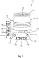
- the turbo-molecular pump 111 shown comprises a pump inlet 115 which is surrounded by an inlet flange 113 and to which a recipient (not shown) can be connected in a manner known per se.
- the gas from the recipient can be sucked out of the recipient via the pump inlet 115 and conveyed through the pump to a pump outlet 117 to which a backing pump, such as a rotary vane pump, can be connected.
- the inlet flange 113 forms according to FIG Fig. 1 the upper end of the housing 119 of the vacuum pump 111.
- the housing 119 comprises a lower part 121 on which an electronics housing 123 is arranged laterally. Electrical and / or electronic components of the vacuum pump 111 are accommodated in the electronics housing 123, for example for operating an electric motor 125 arranged in the vacuum pump (see also FIG Fig. 3 ).
- Several connections 127 for accessories are provided on the electronics housing 123.
- a data interface 129 for example in accordance with the RS485 standard, and a power supply connection 131 are arranged on the electronics housing 123.
- turbomolecular pumps that do not have an electronic housing attached in this way, but are connected to external drive electronics.
- a flood inlet 133 in particular in the form of a flood valve, is provided on the housing 119 of the turbo molecular pump 111, via which the vacuum pump 111 can be flooded.
- a sealing gas connection 135, which is also referred to as a purging gas connection via which purging gas to protect the electric motor 125 (see e.g. Fig. 3 ) can be admitted into the engine compartment 137, in which the electric motor 125 in the vacuum pump 111 is accommodated, before the gas conveyed by the pump.
- Two coolant connections 139 are also arranged in the lower part 121, one of the coolant connections being provided as an inlet and the other coolant connection being provided as an outlet for coolant which can be passed into the vacuum pump for cooling purposes.
- Other existing turbo-molecular vacuum pumps (not shown) are operated exclusively with air cooling.
- the lower side 141 of the vacuum pump can serve as a standing surface, so that the vacuum pump 111 can be operated standing on the lower side 141.
- the vacuum pump 111 can, however, also be attached to a recipient via the inlet flange 113 and can thus be operated in a suspended manner, as it were.
- the vacuum pump 111 can be designed in such a way that it can also be put into operation when it is oriented in a different way than in FIG Fig. 1 is shown.
- Embodiments of the vacuum pump can also be implemented in which the underside 141 cannot be arranged facing downwards, but facing to the side or facing upwards. In principle, any angle is possible.
- various screws 143 are also arranged by means of which components of the vacuum pump not specified here are attached to each other.
- a bearing cap 145 is attached to the underside 141.
- Fastening bores 147 are also arranged on the underside 141, via which the pump 111 can be fastened to a support surface, for example. This is not possible with other existing turbo-molecular vacuum pumps (not shown), which are in particular larger than the pump shown here.
- a coolant line 148 is shown, in which the coolant introduced and discharged via the coolant connections 139 can circulate.
- the vacuum pump comprises several process gas pump stages for conveying the process gas present at the pump inlet 115 to the pump outlet 117.
- a rotor 149 is arranged in the housing 119 and has a rotor shaft 153 rotatable about an axis of rotation 151.
- the turbo-molecular pump 111 comprises several turbo-molecular pump stages connected in series with one another with several radial rotor disks 155 attached to the rotor shaft 153 and stator disks 157 arranged between the rotor disks 155 and fixed in the housing 119.
- a rotor disk 155 and an adjacent stator disk 157 each form a turbomolecular one Pumping stage.
- the stator disks 157 are held at a desired axial distance from one another by spacer rings 159.
- the vacuum pump also comprises Holweck pump stages which are arranged one inside the other in the radial direction and are connected in series with one another for effective pumping. It there are other turbomolecular vacuum pumps (not shown) that do not have Holweck pump stages.
- the rotor of the Holweck pump stages comprises a rotor hub 161 arranged on the rotor shaft 153 and two cylinder-jacket-shaped Holweck rotor sleeves 163, 165 which are attached to the rotor hub 161 and carried by the latter, which are oriented coaxially to the axis of rotation 151 and nested in one another in the radial direction. Furthermore, two cylinder jacket-shaped Holweck stator sleeves 167, 169 are provided, which are also oriented coaxially to the axis of rotation 151 and, viewed in the radial direction, are nested inside one another.
- the active pumping surfaces of the Holweck pump stages are formed by the jacket surfaces, that is to say by the radial inner and / or outer surfaces, of the Holweck rotor sleeves 163, 165 and the Holweck stator sleeves 167, 169.
- the radial inner surface of the outer Holweck stator sleeve 167 lies opposite the radial outer surface of the outer Holweck rotor sleeve 163, forming a radial Holweck gap 171 and with this forms the first Holweck pumping stage following the turbo molecular pumps.
- the radial inner surface of the outer Holweck rotor sleeve 163 is opposite the radial outer surface of the inner Holweck stator sleeve 169 with the formation of a radial Holweck gap 173 and forms with this a second Holweck pump stage.
- the radial inner surface of the inner Holweck stator sleeve 169 lies opposite the radial outer surface of the inner Holweck rotor sleeve 165 with the formation of a radial Holweck gap 175 and with this forms the third Holweck pumping stage.
- a radially running channel can be provided, via which the radially outer Holweck gap 171 is connected to the central Holweck gap 173.
- a radially running channel can be provided at the upper end of the inner Holweck stator sleeve 169, via which the middle Holweck gap 173 with the radially inner Holweck gap 175 is connected.
- the nested Holweck pump stages are connected in series with one another.
- a connection channel 179 to the outlet 117 can also be provided.
- the aforementioned pump-active surfaces of the Holweck stator sleeves 167, 169 each have a plurality of Holweck grooves running helically around the axis of rotation 151 in the axial direction, while the opposing lateral surfaces of the Holweck rotor sleeves 163, 165 are smooth and the gas for operating the Drive vacuum pump 111 in the Holweck grooves.
- a roller bearing 181 is provided in the area of the pump outlet 117 and a permanent magnetic bearing 183 in the area of the pump inlet 115.
- a conical injection molded nut 185 is provided on the rotor shaft 153 with an outer diameter that increases towards the roller bearing 181.
- the injection-molded nut 185 is in sliding contact with at least one stripper of an operating medium store.
- an injection screw can be provided instead of an injection nut. Since different designs are thus possible, the term "spray tip" is also used in this context.
- the operating medium storage comprises a plurality of absorbent disks 187 stacked on top of one another, which are provided with operating medium for the roller bearing 181, e.g. with a lubricant.
- the operating medium is transferred by capillary action from the operating medium reservoir via the stripper to the rotating injection nut 185 and as a result of the centrifugal force along the injection nut 185 in In the direction of the increasing outer diameter of the injection nut 185 to the roller bearing 181, where it fulfills a lubricating function, for example.
- the roller bearing 181 and the operating medium store are enclosed in the vacuum pump by a trough-shaped insert 189 and the bearing cover 145.
- the permanent magnetic bearing 183 comprises a rotor-side bearing half 191 and a stator-side bearing half 193, each of which comprises a ring stack of several permanent magnetic rings 195, 197 stacked on top of one another in the axial direction.
- the ring magnets 195, 197 are opposite one another with the formation of a radial bearing gap 199, the rotor-side ring magnets 195 being arranged radially on the outside and the stator-side ring magnets 197 being arranged radially on the inside.
- the magnetic field present in the bearing gap 199 causes magnetic repulsive forces between the ring magnets 195, 197, which cause the rotor shaft 153 to be supported radially.
- the rotor-side ring magnets 195 are carried by a carrier section 201 of the rotor shaft 153 which surrounds the ring magnets 195 radially on the outside.
- the stator-side ring magnets 197 are carried by a stator-side support section 203 which extends through the ring magnets 197 and is suspended from radial struts 205 of the housing 119.
- the ring magnets 195 on the rotor side are fixed parallel to the axis of rotation 151 by a cover element 207 coupled to the carrier section 201.
- the stator-side ring magnets 197 are fixed parallel to the axis of rotation 151 in one direction by a fastening ring 209 connected to the carrier section 203 and a fastening ring 211 connected to the carrier section 203.
- a plate spring 213 can also be provided between the fastening ring 211 and the ring magnet 197.
- An emergency or retainer bearing 215 is provided within the magnetic bearing, which runs idle during normal operation of the vacuum pump 111 without contact and only when the rotor 149 is excessively deflected radially relative to the stator comes into engagement to form a radial stop for the rotor 149, so that a collision of the rotor-side structures with the stator-side structures is prevented.
- the backup bearing 215 is designed as an unlubricated roller bearing and forms a radial gap with the rotor 149 and / or the stator, which has the effect that the backup bearing 215 is disengaged during normal pumping operation.
- the radial deflection at which the backup bearing 215 engages is dimensioned large enough that the backup bearing 215 does not come into engagement during normal operation of the vacuum pump, and at the same time small enough so that a collision of the rotor-side structures with the stator-side structures under all circumstances is prevented.
- the vacuum pump 111 comprises the electric motor 125 for rotatingly driving the rotor 149.
- the armature of the electric motor 125 is formed by the rotor 149, the rotor shaft 153 of which extends through the motor stator 217.
- a permanent magnet arrangement can be arranged radially on the outside or embedded in the section of the rotor shaft 153 extending through the motor stator 217.
- the motor stator 217 is fixed in the housing within the motor compartment 137 provided for the electric motor 125.
- a sealing gas which is also referred to as a flushing gas and which can be air or nitrogen, for example, can enter the engine compartment 137 via the sealing gas connection 135.
- the electric motor 125 can be protected from process gas, for example from corrosive components of the process gas, via the sealing gas.
- the engine compartment 137 can also be evacuated via the pump outlet 117, ie in the engine compartment 137 there is at least approximately the vacuum pressure produced by the backing pump connected to the pump outlet 117.
- a so-called labyrinth seal 223, known per se, can also be provided between the rotor hub 161 and a wall 221 delimiting the engine compartment 137, in particular in order to achieve a better sealing of the motor compartment 217 from the Holweck pump stages located radially outside.
- FIGS. 6 to 11 show stator blades or stator disks in a highly schematic representation.
- the stator disks 157 of the turbo molecular pump 111 of FIG Figs. 1 to 5 can be designed according to the invention, ie the invention can be used in a turbo-molecular pump, as it is based on Figs. 1 to 5 has been described.
- FIGS. 6 and 7 serve to illustrate the state of the art. Both show a stator blade 20 in a cross section, namely with a sectional plane transverse to a direction of extent of the stator blade. This direction of extension runs radially in the pump with respect to the axis of rotation of the rotor.
- the axis of rotation of the rotor is in the Figures 6 to 11 indicated by the dashed line 21.
- the cutting plane of the cross section shown here thus runs parallel to the axis of rotation 21 of the rotor, not shown here, which runs vertically here and in the other figures. Consequently, the blades 20 are inclined with respect to a plane (not shown) which runs perpendicular to the axis of rotation 21 and which runs horizontally in the cross section shown.
- stator disks in turbo molecular pumps are milled from the solid.
- the stator blade 20 of the Fig. 6 is machined, for example by milling and / or sawing.
- a flat disk made of solid material is sawn or milled radially in such a way that the several blades remain.
- the stator blade 20 has flat ends 22 and 24 which run perpendicular to the axis of rotation 21 and thus horizontally and are axial with respect to the axis of rotation 21.
- Fig. 7 illustrates a known stator blade 20 made of sheet metal, which is typically first formed from a flat sheet metal by punching and then brought into the oblique orientation shown here by bending.
- the ends 22 and 24 which are axial with respect to the axis of rotation 21 are not flat, as is the case with the stator blade 20 of FIG Fig. 6 is the case, but essentially angular.
- the stator blade 20 of the Fig. 7 namely, in particular has a substantially rectangular cross section, the corners of the rectangle forming the axial ends 22, 24 of the stator blade 20.
- the milled or sawn blade 20 of the Fig. 6 is parallelogram-shaped in cross-section.
- the stamped from sheet metal blade 20 of the Fig. 7 is rectangular in cross section.
- the blade 20 Due to the different cross-sectional shapes, the blade 20 has Fig. 7 a larger axial installation space with the same pumping effect than that of the Fig. 6 . In other words, with the same axial gaps or with the same axial gaps Overall height the effective pump height of the blade 20 or the stator disk of the Fig. 7 smaller.
- stator disks in existing pumps that is to say to improve existing pump designs in accordance with the object of the invention
- only a certain amount of space is available axially.
- the ultimate goal is to change the contour of the stator blade made of sheet metal so that it is as close as possible to the milled contour - especially as in Fig. 6 - comes up.
- the material triangle of the rectangular cross-section protruding from the axial end (in particular irrelevant in terms of vacuum technology) is flattened so that the blade contour now approximates the parallelogram shape.
- Fig. 8 is a further stator vane 20 with a rectangular cross-section compared to FIG Fig. 7 shown enlarged.
- the axial end 22 can preferably be an upstream end and the axial end 24 can be a downstream end of the stator blade 20.
- a region 26 of the illustrated cross section is marked which is essentially triangular.
- the material of the stator blade 20 in this area 26 is largely irrelevant for the pumping action of the stator blade 20 or the stator disk, that is to say superfluous.
- the pumping direction 28 is marked here by an arrow.
- the pumping direction 28 runs in particular parallel to the axis of rotation 21 of the rotor, not shown here.
- the stator blade 20 of the Fig. 9 therefore has a flattening 32 according to the invention at the axial end 22.
- the area 26 with excess material is significantly smaller and, in particular, the overall axial height of the stator blade 20 and of the relevant stator disk is reduced.
- the flattening 32 is embodied here as an at least essentially flat surface in relation to the three-dimensional extension of the stator blade 20.
- the flattening 32 or the surface runs over the entire radial extent, that is to say over the entire radial length, of the stator blade 20.
- the surface of the flattening 32 runs perpendicular to the axis of rotation 21 of the rotor of the turbo-molecular pump.
- the axial gain in installation space corresponds to the axial distance between the surface and the upper tip of the triangle in Fig. 8 , When it is in Fig. 9 is projected. This triangle is in Fig. 9 indicated by dashed lines and its upstream tip is denoted by 22 '.
- the flattening 32 can be produced in different ways.
- the axial end 22 can be ground off.
- the stator vane 20 is illustrated as one that is flattened not by grinding, but rather by forming, namely extrusion.
- a deformation force was in particular essentially perpendicular to the disk plane or parallel to the axis of rotation 21 of the rotor, in Fig. 9 from top to bottom, applied.
- the material of the area 26 or of the stator blade 20 is reshaped in such a way that it extends in an area that extends over the in Fig.
- the bead 34 is arranged on a flat side 36, which here is the upstream flat side and which points in the same axial direction as the end 22.
- the bead 34 is arranged directly adjacent to the flattening 32.
- the bead 34 is arranged at least essentially in such a way that it does not influence the pumping action of the stator blade 20. This is because the pumping effect is essentially determined by the flat side 30 on the downstream side. However, a comparison shows that in Fig. 9 the area 26 with excess material is axially significantly smaller than that of the Fig. 8 . Thus, the flattening 32 allows the axial installation space of the stator blade 20 or of the stator disk to be reduced in a simple manner, to be precise without any negative effects on the pump performance.
- the excess material or that of the area 26 is ultimately pressed into an area where it no longer interferes, namely not interfering with the axial installation space and the pumping effect.
- the material is preferably pressed against the fluidic rear side, as here against the flat side 36, where it no longer interferes.
- the gain from the flattening is greater, the flatter the blade angle.
- the excess or disturbing triangle can make up to 1/3 of the total height.
- downstream end 24 can also have a flattening, but this is not shown. In this respect, it is also possible to press away the interfering triangle on the underside of the disk or blade 20.
- a stator disk 38 is shown in simplified form, which comprises a collar 40 and a plurality of stator blades 20 connected to the collar 40.
- the collar 40 can be an inner and / or outer collar, for example.
- the collar 40 is arranged axially centrally with respect to the stator blades 20, as is customary in the prior art.
- Fig. 11 illustrates a stator disk 38 according to the invention, in which the collar 40 is arranged axially eccentrically with respect to the stator blades 20.
- the collar 40 With respect to a pumping direction 28 shown in Fig. 11 runs from top to bottom by way of example, the collar 40 is arranged as a whole and with its axial center towards or downstream of the axial center of the stator blade.
- a connection point between the collar 40 and the stator blade 20 is located at the axial height of the collar 40 and is thus also arranged after the axial center of the stator blade 20.
- the blade plane that is to say the plane of the axial blade center points, is consequently not positioned centrally with respect to the collar 40, but is axially displaced and thus asymmetrical. This makes it easier to remove the disk 38 again during dismantling, since the probability of a collision of the in Fig. 11 lower blade sections is reduced with other components.
- the stator disks 38 of the Figures 10 and 11 can for example be made of sheet metal and are shown here with pointed axial ends 22 and 24, similar to FIG Figures 7 and 8 .
- the axial direction or the axis of rotation 21 again runs vertically, as in FIG Figures 6 to 9 . Consequently, here too the blades 20 are inclined with respect to a disk plane (not shown) running perpendicular to the axis of rotation 21, in which the collar 40 lies and which consequently runs horizontally.
- a disk plane not shown
- the axial ends 22 and / or 24 can also have a flattening, for example such as in FIG Fig. 9 shown, in particular to save axial space.
Landscapes
- Engineering & Computer Science (AREA)
- Mechanical Engineering (AREA)
- General Engineering & Computer Science (AREA)
- Physics & Mathematics (AREA)
- Geometry (AREA)
- Non-Positive Displacement Air Blowers (AREA)
Abstract
Description
- Die vorliegende Erfindung betrifft eine Turbomolekularpumpe umfassend: einen Rotor mit einer Mehrzahl von über seinen Umfang verteilt angeordneten Rotorschaufeln, der zu einer Rotation um eine Rotationsachse antreibbar ist, um eine Pumpwirkung zu erzeugen, und wenigstens eine Statorscheibe, welche eine Mehrzahl von über ihren Umfang verteilt angeordneten Statorschaufeln aufweist und mit welcher der Rotor zur Erzeugung der Pumpwirkung zusammenwirkt, wobei die Statorschaufeln der Statorscheibe in Bezug auf eine Scheibenebene, welche senkrecht zur Rotationsachse des Rotors verläuft, schräg ausgerichtet sind.
- Die Erfindung betrifft auch ein Verfahren zur Herstellung einer Statorscheibe mit einer Mehrzahl von über ihren Umfang verteilt angeordneten Statorschaufeln für eine Turbomolekularpumpe.
- Statorscheiben für Turbomolekularpumpen werden üblicherweise entweder spanend aus einem Vollmaterial hergestellt, z.B. gefräst oder gesägt, oder aus Blech herstellt. Bei der Herstellung aus Blech werden die Statorschaufeln typischerweise ausgestanzt und anschließend durch Biegen schräg in Bezug auf eine Scheibenebene ausgerichtet. Die Scheibenebene ist eine solche, die bei zusammengebauter Pumpe senkrecht zur Rotationsachse des Rotors verläuft, und ist z.B. durch wenigstens einen Bund der Statorscheibe definiert.
- Die Herstellung von Statorscheiben aus Blech ist besonders kostengünstig, weist aber den Nachteil auf, dass bei vergleichbarer Performance mehr axialer Bauraum für aus Blech hergestellte Statorscheiben nötig ist als für spanend hergestellte Statorscheiben. Der Grund hierfür ist, dass die unterschiedlichen Herstellungsverfahren zu unterschiedlichen Geometrien der Statorschaufeln führen.
- Es ist eine Aufgabe der Erfindung, den axialen Bauraum einer aus Blech herstellten Statorscheibe zu verringern, insbesondere ohne Einschränkung der Vakuumperformance.
- Ein in diesem Zusammenhang offensichtlicher Ansatz bestünde darin, die Statorschaufeln einfach "weniger schräg" auszurichten, also ihren Winkel in Bezug auf die Scheibenebene zu verringern. Dies hat allerdings erhebliche Auswirkungen auf die Pumpwirkung der Statorscheibe und somit auf die Vakuumperformance.
- Die Aufgabe wird vielmehr durch eine Turbomolekularpumpe mit den Merkmalen nach Anspruch 1 gelöst, und insbesondere dadurch, dass wenigstens eine Statorschaufel an wenigstens einem axialen Ende eine Abplattung aufweist.
- Hierdurch ist das Material der Statorschaufel insbesondere genau dort abgeplattet, wo es einerseits den axialen Bauraum der Statorschaufel definiert und andererseits eine in Bezug auf die Pumpperformance relativ geringe Rolle spielt, insbesondere zumindest im Wesentlichen keine pumpaktive Wirkung aufweist. Zudem lässt sich eine solche Abplattung mit einfachen Mitteln erzeugen, sodass die Erfindung die Bauraumoptimierung bei zumindest im Wesentlichen gleichbleibender Pumpperformance mit konstruktiv besonders einfachen Mitteln ermöglicht.
- Die Abplattung kann durch Materialwegnahme oder durch Materialverdrängung erzeugt werden. Hierauf wird an anderer Stelle näher eingegangen.
- Der Begriff "axial" bezieht sich allgemein auf die Rotationsachse des Rotors bzw. eine hierzu parallele Richtung. Das axiale Ende befindet sich somit axial am höchsten oder am niedrigsten Punkt der Statorschaufel in einer aufrechtstehenden Pumpe. Zur Rotationsachse ist typischerweise auch eine Pumprichtung zumindest im Wesentlichen parallel, sodass die axialen Enden der Statorscheibe insbesondere ein stromaufwärtsseitiges und ein stromabwärtsseitiges Ende bilden.
- Die wenigstens eine Statorschaufel kann z.B. nur an einem axialen Ende eine Abplattung aufweisen oder es kann z.B. an zwei gegenüberliegenden axialen Enden jeweils eine Abplattung vorgesehen sein.
- Gemäß einer Ausführungsform ist vorgesehen, dass die Abplattung eine zumindest im Wesentlichen ebene Fläche umfasst. Eine solche Fläche lässt sich mit einfachen Mitteln herstellen und ermöglicht somit auf einfache Weise eine relativ große Bauraumeinsparung.
- Die Fläche kann bevorzugt zumindest im Wesentlich parallel zur Scheibenebene verlaufen. Dies ermöglicht eine besonders große Bauraumeinsparung.
- Weiter bevorzugt kann sich die Abplattung über die gesamte Länge der Statorschaufel erstrecken. Die Länge der Statorschaufel entspricht ihrer Erstreckung in zumindest im Wesentlichen radialer Richtung, wobei sich die Angabe "radial" auf die Rotationsachse des Rotors bezieht.
- Generell kann das axiale Ende ein stromaufwärtsseitiges Ende oder ein stromabwärtsseitiges Ende der Statorschaufel sein. Es ist aber auch möglich, dass sowohl ein stromaufwärtsseitiges Ende als auch ein stromabwärtsseitiges Ende der Statorschaufel eine Abplattung aufweisen. In diesem Fall kann die Bauraumeinsparung gleich doppelt erzielt werden.
- Bevorzugt können mehrere oder alle Statorschaufeln der Statorscheibe eine Abplattung aufweisen, insbesondere am entsprechenden axialen Ende, also alle am stromaufwärtsseitigen und/oder am stromabwärtsseitigen Ende. Eine Turbomolekularpumpe weist häufig mehrere Statorscheiben auf. Hier ist es besonders vorteilhaft, wenn mehrere oder alle Statorscheiben Statorschaufeln mit Abplattung aufweisen.
- Die Aufgabe der Erfindung wird auch durch ein Verfahren zur Herstellung einer Statorscheibe nach dem hierauf gerichteten, unabhängigen Anspruch gelöst. Dieses dient der Herstellung einer Statorscheibe mit einer Mehrzahl von über ihren Umfang verteilt angeordneten Statorschaufeln für eine Turbomolekularpumpe, insbesondere eine solche nach vorstehend beschriebener Art, und umfasst, dass die Statorscheibe aus Blech hergestellt wird, die Statorschaufeln der Statorscheibe in Bezug auf eine Erstreckungsebene des Blechs schräg ausgerichtet werden, und dass wenigstens eine Statorschaufel an wenigstens einem Ende in Bezug auf eine Normale zur Erstreckungsebene des Blechs abgeplattet wird. Allgemein umfasst die Erfindung auch ein entsprechendes Herstellungsverfahren für eine Turbomolekularpumpe mit derart hergestellter Statorscheibe.
- Die Erstreckungsebene des Blechs entspricht bevorzugt einer Scheibenebene, die insbesondere bei zusammengebauter Pumpe senkrecht zur Rotationsachse ist. Insbesondere verbleibt beim Ausrichten der Statorschaufel ein Bund, der die Statorschaufel trägt, in der Erstreckungsebene des Blechs. In diesem Fall kann sich auf die Erstreckungsebene des Bundes bezogen werden. Die Normale ist insbesondere parallel zur Rotationsachse des Rotors bei zusammengebauter Pumpe ausgerichtet.
- Gemäß einer Weiterbildung ist vorgesehen, dass das Abplatten ein Umformen, insbesondere Kaltumformen und/oder Pressen, umfasst. Insbesondere wird die Statorschaufel dabei nicht flächig verbogen, sondern im Wesentlichen im Querschnitt der Statorscheibe gestaucht. Generell insbesondere wird das Material fließend und/oder durch Fließpressen verformt. Allgemein bevorzugt wird das Material der Statorschaufel aufgeschoben, insbesondere sodass es sich in einem zu dem axialen Ende benachbarten Bereich aufwirft. Grundsätzlich kann zum Abplatten beispielsweise eine Umform- und/oder Presskraft zumindest im Wesentlichen parallel zur Normalen bzw. Rotationsachse des Rotors auf die Statorschaufel bzw. auf das Ende aufgebracht werden. Während des Abplattens kann die Statorschaufel bevorzugt auf einer der Abplattung abgewandten Flachseite, bevorzugt flächig, abgestützt sein.
- Alternativ oder zusätzlich ist es z.B. auch möglich, die Abplattung spanend zu bearbeiten oder herzustellen, beispielsweise durch Schleifen.
- Generell kann das Abplatten insbesondere an einer Ecke eines Querschnitts der Statorschaufel erfolgen. Allgemein wird bevorzugt an der betreffenden Ecke ein Materialabschnitt von seiner Position entfernt, entweder durch Umformen verschoben oder, beispielsweise spanend, von der Statorschaufel getrennt. Der zu entfernende Materialabschnitt ist bevorzugt im Querschnitt zumindest im Wesentlichen dreieckig. Die oben erwähnte Fläche der Abplattung definiert insbesondere eine Seite dieses Dreiecks, nämlich insbesondere eine solche, die bezogen auf den Querschnitt der Statorschaufel einem Flächenschwerpunkt derselben zugewandt ist.
- Allgemein kann die Statorschaufel insbesondere eine erste Flachseite, die in die gleiche Richtung in Bezug auf die Normale weist wie das abgeplattete Ende, und/oder eine zweite Flachseite aufweisen, die entgegen dieser Richtung weist. In Bezug auf die Pumprichtung handelt es sich insbesondere um eine in Pumprichtung obere bzw. erste und eine in Pumprichtung untere bzw. zweite Seite. Es versteht sich, dass die Flachseiten allgemein schräg ausgerichtet sind, aber einer der beiden entgegengesetzten Richtungen entlang der Normalen zugewandt sind, dass sie also in die entsprechende Richtung weisen.
- Gemäß einer Ausführungsform ist vorgesehen, dass das Abplatten umfasst, dass ein Material der Statorschaufel, insbesondere hauptsächlich, in Richtung der ersten Flachseite, insbesondere fließend, verschoben wird. Mit Bezug auf die oben beschriebene Turbomolekularpumpe bedeutet dies insbesondere, dass die Statorschaufel an einer ersten Flachseite, die in die gleiche Richtung in Bezug auf die Rotationsachse des Rotors weist, wie das abgeplattete Ende, eine Materialanhäufung aufweist. Diese kann insbesondere einen Vorsprung und/oder eine Wulst bilden und/oder insbesondere unmittelbar bei der Abplattung angeordnet sein. Die erste Flachseite ist insbesondere eine Oberseite der Schaufel in der aufrecht stehenden Pumpe und/oder eine stromaufwärtsseitige Flachseite, wobei insbesondere das betreffende Ende ein stromaufwärtsseitiges Ende ist. Beispielsweise kann aber auch das stromabwärtsseitige Ende abgeplattet werden, insbesondere wobei eine Materialanhäufung an der stromabwärtsseitigen Flachseite erzeugt wird.
- Allgemein beispielsweise können Statorschaufeln durch Stanzen geformt werden und/oder durch Biegen schräg ausgerichtet werden. Das Abplatten kann z.B. ein zusätzlicher Verfahrensschritt oder ein Teil eines zusätzlichen Verfahrensschritts sein oder grundsätzlich auch in einem Verfahrensschritt mit dem Formen und/oder Ausrichten vorgesehen sein. Grundsätzlich kann das Abplatten insbesondere vor, während und/oder nach dem Stanzen und/oder Biegen erfolgen.
- Ein weiterer Aspekt der Erfindung schlägt eine Turbomolekularpumpe nach Anspruch 11 vor. Diese kann beispielsweise nach vorstehend beschriebener Art ausgebildet und/oder hergestellt oder herstellbar sein und umfasst einen Rotor mit einer Mehrzahl von über seinen Umfang verteilt angeordneten Rotorschaufeln, der zu einer Rotation um eine Rotationsachse antreibbar ist, um eine Pumpwirkung zu erzeugen, und wenigstens eine Statorscheibe, welche eine Mehrzahl von über ihren Umfang verteilt angeordneten Statorschaufeln aufweist und mit welcher der Rotor zur Erzeugung der Pumpwirkung zusammenwirkt. Die Statorschaufeln der Statorscheibe sind in Bezug auf eine Scheibenebene, welche senkrecht zur Rotationsachse des Rotors verläuft, schräg ausgerichtet, wobei die Statorschaufeln von wenigstens einem Bund, insbesondere Innen- und/oder Außenbund, getragen werden. Der Bund ist in Bezug auf wenigstens eine Statorschaufel axial außermittig angeordnet. Insbesondere kann der Bund in Bezug auf alle Statorschaufeln der Statorscheibe axial außermittig angeordnet sein.
- Der Bund ist also insbesondere nicht auf Höhe der axialen Mitte der Schaufel, sondern hierzu axial versetzt angeordnet. Die außermittige Anordnung ermöglicht eine Vereinfachung der Montage und insbesondere der Demontage der Pumpe. Die Statorscheibe lässt sich durch die außermittige Anordnung des Bundes einfacher aus der Pumpe entnehmen.
- Insbesondere bei einer solchen Anordnung, bei der die Statorscheibe zwecks Demontage radial zwischen zwei Rotorscheiben herausgeführt bzw. zwecks Montage hineingeführt wird - dabei weist die Statorscheibe insbesondere wenigstens zwei separierbare Ringsegmente auf -, wird hierdurch auf der axialen Seite, zu der der Bund hin versetzt ist, die Kollisionsgefahr mit einem sonstigen Statorelement, insbesondere einem Distanzring, verringert, weil dort die Statorschaufeln dann axial kürzer sind. Zwar würde hiermit theoretisch auf der anderen axialen Seite eine Kollisionsgefahr erhöht, jedoch erlaubt es meist eine bestimmte Montagereihenfolge, dass auf dieser anderen axialen Seite kein solches Element, insbesondere Distanzring, angeordnet ist, wenn die betreffende Statorscheibe zur Entnahme "an der Reihe" ist.
- Bevorzugt kann es vorgesehen sein, dass der Bund, eine Verbindungsstelle zwischen Bund und jeweiliger Statorschaufel und/oder eine axiale Mitte des Bundes vor oder nach der axialen Mitte der Statorschaufel in Bezug auf eine Pumprichtung angeordnet sind. Bei einer aufrechtstehenden Pumpe entspricht dies insbesondere einer Anordnung oberhalb bzw. unterhalb der axialen Mitte der Statorschaufel.
- Eine Statorscheibe kann z.B. einen Außenbund und/oder einen Innenbund aufweisen. Grundsätzlich können ein Außen- und ein Innenbund der Statorscheibe auf gleicher oder unterschiedlicher axialer Höhe angeordnet sein. Die Begriffe "außen" und "innen" beziehen sich hier auf die Rotationsachse des Rotors, bedeuten also radial außen und radial innen.
- Bei einigen Ausführungsformen ist der Bund axial außermittig in Bezug auf mehrere, insbesondere alle, Statorschaufeln angeordnet. Dies gilt bevorzugt für den gesamten Bund und/oder für einen Außen- und/oder Innenbund. Allgemein können die Statorschaufeln insbesondere auf axial gleicher Höhe angeordnet sein.
- Grundsätzlich kann ein Bund beispielsweise ringförmig ausgebildet sein, insbesondere durchgehend ringförmig oder mit mehreren Ringsegmenten. Z.B. kann ein Innenbund durchgehend ringförmig und ein Außenbund mit mehrere Ringsegmenten ausgebildet sein. Dabei ist zu berücksichtigen, dass die Statorscheibe selbst bevorzugt aus Ringsegmenten hergestellt sein kann, d.h. "durchgehend" bezieht sich dann auf das betreffende Ringsegment der Statorscheibe.
- Eine Statorscheibe kann allgemein bevorzugt aus Blech, insbesondere mittels Stanzen und/oder Biegen, herstellt sein. Allgemein kann eine Statorscheibe beispielsweise aus wenigstens zwei Teilringen, insbesondere Halbringen, zusammengesetzt sein.
- Es versteht sich, dass die hier beschriebenen Turbomolekularpumpen und Herstellungsverfahren mittels der Ausführungsformen und Einzelmerkmale der jeweils anderen hier beschriebenen Turbomolekularpumpen bzw. Herstellungsverfahren einzeln und in Kombination vorteilhaft weitergebildet werden können.
- Nachfolgend wird die Erfindung beispielhaft anhand vorteilhafter Ausführungsformen unter Bezugnahme auf die beigefügten Figuren beschrieben. Es zeigen, jeweils schematisch:
- Fig. 1
- eine perspektivische Ansicht einer Turbomolekularpumpe,
- Fig. 2
- eine Ansicht der Unterseite der Turbomolekularpumpe von
Fig. 1 , - Fig. 3
- einen Querschnitt der Turbomolekularpumpe längs der in
Fig. 2 gezeigten Schnittlinie A-A, - Fig. 4
- eine Querschnittsansicht der Turbomolekularpumpe längs der in
Fig. 2 gezeigten Schnittlinie B-B, - Fig. 5
- eine Querschnittsansicht der Turbomolekularpumpe längs der in
Fig. 2 gezeigten Schnittlinie C-C, - Fig. 6
- eine spanend aus Vollmaterial hergestellte Statorschaufel des Standes der Technik im Querschnitt mit Schnittebene quer zur Erstreckungsrichtung der Statorschaufel,
- Fig. 7
- eine aus Blech hergestellte Statorschaufel des Standes der Technik im Querschnitt,
- Fig. 8
- eine aus Blech hergestellte Statorschaufel im Querschnitt mit Kennzeichnung von überschüssigem Material,
- Fig. 9
- die Statorschaufel der
Fig. 8 nach einem Abplatten, - Fig. 10
- eine Statorscheibe des Standes der Technik in einer stark vereinfachten Seitenansicht,
- Fig. 11
- eine Statorscheibe mit außermittig in Bezug auf die Statorschaufeln angeordnetem Bund in einer derjenigen der
Fig. 10 entsprechenden Ansicht. - Die in
Fig. 1 gezeigte Turbomolekularpumpe 111 umfasst einen von einem Einlassflansch 113 umgebenen Pumpeneinlass 115, an welchen in an sich bekannter Weise ein nicht dargestellter Rezipient angeschlossen werden kann. Das Gas aus dem Rezipienten kann über den Pumpeneinlass 115 aus dem Rezipienten gesaugt und durch die Pumpe hindurch zu einem Pumpenauslass 117 gefördert werden, an den eine Vorvakuumpumpe, wie etwa eine Drehschieberpumpe, angeschlossen sein kann. - Der Einlassflansch 113 bildet bei der Ausrichtung der Vakuumpumpe gemäß
Fig. 1 das obere Ende des Gehäuses 119 der Vakuumpumpe 111. Das Gehäuse 119 umfasst ein Unterteil 121, an welchem seitlich ein Elektronikgehäuse 123 angeordnet ist. In dem Elektronikgehäuse 123 sind elektrische und/oder elektronische Komponenten der Vakuumpumpe 111 untergebracht, z.B. zum Betreiben eines in der Vakuumpumpe angeordneten Elektromotors 125 (vgl. auchFig. 3 ). Am Elektronikgehäuse 123 sind mehrere Anschlüsse 127 für Zubehör vorgesehen. Außerdem sind eine Datenschnittstelle 129, z.B. gemäß dem RS485-Standard, und ein Stromversorgungsanschluss 131 am Elektronikgehäuse 123 angeordnet. - Es existieren auch Turbomolekularpumpen, die kein derartiges angebrachtes Elektronikgehäuse aufweisen, sondern an eine externe Antriebselektronik angeschlossen werden.
- Am Gehäuse 119 der Turbomolekularpumpe 111 ist ein Fluteinlass 133, insbesondere in Form eines Flutventils, vorgesehen, über den die Vakuumpumpe 111 geflutet werden kann. Im Bereich des Unterteils 121 ist ferner noch ein Sperrgasanschluss 135, der auch als Spülgasanschluss bezeichnet wird, angeordnet, über welchen Spülgas zum Schutz des Elektromotors 125 (siehe z.B.
Fig. 3 ) vor dem von der Pumpe geförderten Gas in den Motorraum 137, in welchem der Elektromotor 125 in der Vakuumpumpe 111 untergebracht ist, eingelassen werden kann. Im Unterteil 121 sind ferner noch zwei Kühlmittelanschlüsse 139 angeordnet, wobei einer der Kühlmittelanschlüsse als Einlass und der andere Kühlmittelanschluss als Auslass für Kühlmittel vorgesehen ist, das zu Kühlzwecken in die Vakuumpumpe geleitet werden kann. Andere existierende Turbomolekularvakuumpumpen (nicht dargestellt) werden ausschließlich mit Luftkühlung betrieben. - Die untere Seite 141 der Vakuumpumpe kann als Standfläche dienen, sodass die Vakuumpumpe 111 auf der Unterseite 141 stehend betrieben werden kann. Die Vakuumpumpe 111 kann aber auch über den Einlassflansch 113 an einem Rezipienten befestigt werden und somit gewissermaßen hängend betrieben werden. Außerdem kann die Vakuumpumpe 111 so gestaltet sein, dass sie auch in Betrieb genommen werden kann, wenn sie auf andere Weise ausgerichtet ist als in
Fig. 1 gezeigt ist. Es lassen sich auch Ausführungsformen der Vakuumpumpe realisieren, bei der die Unterseite 141 nicht nach unten, sondern zur Seite gewandt oder nach oben gerichtet angeordnet werden kann. Grundsätzlich sind dabei beliebige Winkel möglich. - Andere existierende Turbomolekularvakuumpumpen (nicht dargestellt), die insbesondere größer sind als die hier dargestellte Pumpe, können nicht stehend betrieben werden.
- An der Unterseite 141, die in
Fig. 2 dargestellt ist, sind noch diverse Schrauben 143 angeordnet, mittels denen hier nicht weiter spezifizierte Bauteile der Vakuumpumpe aneinander befestigt sind. Beispielsweise ist ein Lagerdeckel 145 an der Unterseite 141 befestigt. - An der Unterseite 141 sind außerdem Befestigungsbohrungen 147 angeordnet, über welche die Pumpe 111 beispielsweise an einer Auflagefläche befestigt werden kann. Dies ist bei anderen existierenden Turbomolekularvakuumpumpen (nicht dargestellt), die insbesondere größer sind als die hier dargestellte Pumpe, nicht möglich.
- In den
Figuren 2 bis 5 ist eine Kühlmittelleitung 148 dargestellt, in welcher das über die Kühlmittelanschlüsse 139 ein- und ausgeleitete Kühlmittel zirkulieren kann. - Wie die Schnittdarstellungen der
Figuren 3 bis 5 zeigen, umfasst die Vakuumpumpe mehrere Prozessgaspumpstufen zur Förderung des an dem Pumpeneinlass 115 anstehenden Prozessgases zu dem Pumpenauslass 117. - In dem Gehäuse 119 ist ein Rotor 149 angeordnet, der eine um eine Rotationsachse 151 drehbare Rotorwelle 153 aufweist.
- Die Turbomolekularpumpe 111 umfasst mehrere pumpwirksam miteinander in Serie geschaltete turbomolekulare Pumpstufen mit mehreren an der Rotorwelle 153 befestigten radialen Rotorscheiben 155 und zwischen den Rotorscheiben 155 angeordneten und in dem Gehäuse 119 festgelegten Statorscheiben 157. Dabei bilden eine Rotorscheibe 155 und eine benachbarte Statorscheibe 157 jeweils eine turbomolekulare Pumpstufe. Die Statorscheiben 157 sind durch Abstandsringe 159 in einem gewünschten axialen Abstand zueinander gehalten.
- Die Vakuumpumpe umfasst außerdem in radialer Richtung ineinander angeordnete und pumpwirksam miteinander in Serie geschaltete Holweck-Pumpstufen. Es existieren andere Turbomolekularvakuumpumpen (nicht dargestellt), die keine Holweck-Pumpstufen aufweisen.
- Der Rotor der Holweck-Pumpstufen umfasst eine an der Rotorwelle 153 angeordnete Rotornabe 161 und zwei an der Rotornabe 161 befestigte und von dieser getragene zylindermantelförmige Holweck-Rotorhülsen 163, 165, die koaxial zur Rotationsachse 151 orientiert und in radialer Richtung ineinander geschachtelt sind. Ferner sind zwei zylindermantelförmige Holweck-Statorhülsen 167, 169 vorgesehen, die ebenfalls koaxial zu der Rotationsachse 151 orientiert und in radialer Richtung gesehen ineinander geschachtelt sind.
- Die pumpaktiven Oberflächen der Holweck-Pumpstufen sind durch die Mantelflächen, also durch die radialen Innen- und/oder Außenflächen, der Holweck-Rotorhülsen 163, 165 und der Holweck-Statorhülsen 167, 169 gebildet. Die radiale Innenfläche der äußeren Holweck-Statorhülse 167 liegt der radialen Außenfläche der äußeren Holweck-Rotorhülse 163 unter Ausbildung eines radialen Holweck-Spalts 171 gegenüber und bildet mit dieser die der Turbomolekularpumpen nachfolgende erste Holweck-Pumpstufe. Die radiale Innenfläche der äußeren Holweck-Rotorhülse 163 steht der radialen Außenfläche der inneren Holweck-Statorhülse 169 unter Ausbildung eines radialen Holweck-Spalts 173 gegenüber und bildet mit dieser eine zweite Holweck-Pumpstufe. Die radiale Innenfläche der inneren Holweck-Statorhülse 169 liegt der radialen Außenfläche der inneren Holweck-Rotorhülse 165 unter Ausbildung eines radialen Holweck-Spalts 175 gegenüber und bildet mit dieser die dritte Holweck-Pumpstufe.
- Am unteren Ende der Holweck-Rotorhülse 163 kann ein radial verlaufender Kanal vorgesehen sein, über den der radial außenliegende Holweck-Spalt 171 mit dem mittleren Holweck-Spalt 173 verbunden ist. Außerdem kann am oberen Ende der inneren Holweck-Statorhülse 169 ein radial verlaufender Kanal vorgesehen sein, über den der mittlere Holweck-Spalt 173 mit dem radial innenliegenden Holweck-Spalt 175 verbunden ist. Dadurch werden die ineinander geschachtelten Holweck-Pumpstufen in Serie miteinander geschaltet. Am unteren Ende der radial innenliegenden Holweck-Rotorhülse 165 kann ferner ein Verbindungskanal 179 zum Auslass 117 vorgesehen sein.
- Die vorstehend genannten pumpaktiven Oberflächen der Holweck-Statorhülsen 167, 169 weisen jeweils mehrere spiralförmig um die Rotationsachse 151 herum in axialer Richtung verlaufende Holweck-Nuten auf, während die gegenüberliegenden Mantelflächen der Holweck-Rotorhülsen 163, 165 glatt ausgebildet sind und das Gas zum Betrieb der Vakuumpumpe 111 in den Holweck-Nuten vorantreiben.
- Zur drehbaren Lagerung der Rotorwelle 153 sind ein Wälzlager 181 im Bereich des Pumpenauslasses 117 und ein Permanentmagnetlager 183 im Bereich des Pumpeneinlasses 115 vorgesehen.
- Im Bereich des Wälzlagers 181 ist an der Rotorwelle 153 eine konische Spritzmutter 185 mit einem zu dem Wälzlager 181 hin zunehmenden Außendurchmesser vorgesehen. Die Spritzmutter 185 steht mit mindestens einem Abstreifer eines Betriebsmittelspeichers in gleitendem Kontakt. Bei anderen existierenden Turbomolekularvakuumpumpen (nicht dargestellt) kann anstelle einer Spritzmutter eine Spritzschraube vorgesehen sein. Da somit unterschiedliche Ausführungen möglich sind, wird in diesem Zusammenhang auch der Begriff "Spritzspitze" verwendet.
- Der Betriebsmittelspeicher umfasst mehrere aufeinander gestapelte saugfähige Scheiben 187, die mit einem Betriebsmittel für das Wälzlager 181, z.B. mit einem Schmiermittel, getränkt sind.
- Im Betrieb der Vakuumpumpe 111 wird das Betriebsmittel durch kapillare Wirkung von dem Betriebsmittelspeicher über den Abstreifer auf die rotierende Spritzmutter 185 übertragen und in Folge der Zentrifugalkraft entlang der Spritzmutter 185 in Richtung des größer werdenden Außendurchmessers der Spritzmutter 185 zu dem Wälzlager 181 hin gefördert, wo es z.B. eine schmierende Funktion erfüllt. Das Wälzlager 181 und der Betriebsmittelspeicher sind durch einen wannenförmigen Einsatz 189 und den Lagerdeckel 145 in der Vakuumpumpe eingefasst.
- Das Permanentmagnetlager 183 umfasst eine rotorseitige Lagerhälfte 191 und eine statorseitige Lagerhälfte 193, welche jeweils einen Ringstapel aus mehreren in axialer Richtung aufeinander gestapelten permanentmagnetischen Ringen 195, 197 umfassen. Die Ringmagnete 195, 197 liegen einander unter Ausbildung eines radialen Lagerspalts 199 gegenüber, wobei die rotorseitigen Ringmagnete 195 radial außen und die statorseitigen Ringmagnete 197 radial innen angeordnet sind. Das in dem Lagerspalt 199 vorhandene magnetische Feld ruft magnetische Abstoßungskräfte zwischen den Ringmagneten 195, 197 hervor, welche eine radiale Lagerung der Rotorwelle 153 bewirken. Die rotorseitigen Ringmagnete 195 sind von einem Trägerabschnitt 201 der Rotorwelle 153 getragen, welcher die Ringmagnete 195 radial außenseitig umgibt. Die statorseitigen Ringmagnete 197 sind von einem statorseitigen Trägerabschnitt 203 getragen, welcher sich durch die Ringmagnete 197 hindurch erstreckt und an radialen Streben 205 des Gehäuses 119 aufgehängt ist. Parallel zu der Rotationsachse 151 sind die rotorseitigen Ringmagnete 195 durch ein mit dem Trägerabschnitt 201 gekoppeltes Deckelelement 207 festgelegt. Die statorseitigen Ringmagnete 197 sind parallel zu der Rotationsachse 151 in der einen Richtung durch einen mit dem Trägerabschnitt 203 verbundenen Befestigungsring 209 sowie einen mit dem Trägerabschnitt 203 verbundenen Befestigungsring 211 festgelegt. Zwischen dem Befestigungsring 211 und den Ringmagneten 197 kann außerdem eine Tellerfeder 213 vorgesehen sein.
- Innerhalb des Magnetlagers ist ein Not- bzw. Fanglager 215 vorgesehen, welches im normalen Betrieb der Vakuumpumpe 111 ohne Berührung leer läuft und erst bei einer übermäßigen radialen Auslenkung des Rotors 149 relativ zu dem Stator in Eingriff gelangt, um einen radialen Anschlag für den Rotor 149 zu bilden, damit eine Kollision der rotorseitigen Strukturen mit den statorseitigen Strukturen verhindert wird. Das Fanglager 215 ist als ungeschmiertes Wälzlager ausgebildet und bildet mit dem Rotor 149 und/oder dem Stator einen radialen Spalt, welcher bewirkt, dass das Fanglager 215 im normalen Pumpbetrieb außer Eingriff ist. Die radiale Auslenkung, bei der das Fanglager 215 in Eingriff gelangt, ist groß genug bemessen, sodass das Fanglager 215 im normalen Betrieb der Vakuumpumpe nicht in Eingriff gelangt, und gleichzeitig klein genug, sodass eine Kollision der rotorseitigen Strukturen mit den statorseitigen Strukturen unter allen Umständen verhindert wird.
- Die Vakuumpumpe 111 umfasst den Elektromotor 125 zum drehenden Antreiben des Rotors 149. Der Anker des Elektromotors 125 ist durch den Rotor 149 gebildet, dessen Rotorwelle 153 sich durch den Motorstator 217 hindurch erstreckt. Auf den sich durch den Motorstator 217 hindurch erstreckenden Abschnitt der Rotorwelle 153 kann radial außenseitig oder eingebettet eine Permanentmagnetanordnung angeordnet sein. Zwischen dem Motorstator 217 und dem sich durch den Motorstator 217 hindurch erstreckenden Abschnitt des Rotors 149 ist ein Zwischenraum 219 angeordnet, welcher einen radialen Motorspalt umfasst, über den sich der Motorstator 217 und die Permanentmagnetanordnung zur Übertragung des Antriebsmoments magnetisch beeinflussen können.
- Der Motorstator 217 ist in dem Gehäuse innerhalb des für den Elektromotor 125 vorgesehenen Motorraums 137 festgelegt. Über den Sperrgasanschluss 135 kann ein Sperrgas, das auch als Spülgas bezeichnet wird, und bei dem es sich beispielsweise um Luft oder um Stickstoff handeln kann, in den Motorraum 137 gelangen. Über das Sperrgas kann der Elektromotor 125 vor Prozessgas, z.B. vor korrosiv wirkenden Anteilen des Prozessgases, geschützt werden. Der Motorraum 137 kann auch über den Pumpenauslass 117 evakuiert werden, d.h. im Motorraum 137 herrscht zumindest annäherungsweise der von der am Pumpenauslass 117 angeschlossenen Vorvakuumpumpe bewirkte Vakuumdruck.
- Zwischen der Rotornabe 161 und einer den Motorraum 137 begrenzenden Wandung 221 kann außerdem eine sog. und an sich bekannte Labyrinthdichtung 223 vorgesehen sein, insbesondere um eine bessere Abdichtung des Motorraums 217 gegenüber den radial außerhalb liegenden Holweck-Pumpstufen zu erreichen.
- Die
Fig. 6 bis 11 zeigen Statorschaufeln bzw. Statorscheiben in stark schematisierter Darstellung. Die Statorscheiben 157 der Turbomolekularpumpe 111 derFig. 1 bis 5 können erfindungsgemäß ausgebildet sein, d.h. die Erfindung kann in einer Turbomolekularpumpe eingesetzt werden, wie sie anhand derFig. 1 bis 5 beschrieben worden ist. - Die
Fig. 6 und 7 dienen der Illustration des Standes der Technik. Beide zeigen eine Statorschaufel 20 in einem Querschnitt, nämlich mit Schnittebene quer zu einer Erstreckungsrichtung der Statorschaufel. Diese Erstreckungsrichtung verläuft in der Pumpe radial in Bezug auf die Rotationsachse des Rotors. Die Rotationsachse des Rotors ist in denFig. 6 bis 11 durch die gestrichelte Linie 21 angedeutet. Die Schnittebene des hier dargestellten Querschnitts verläuft also parallel zur Rotationsachse 21 des hier nicht dargestellten Rotors, die hier und in den weiteren Figuren vertikal verläuft. Folglich sind die Schaufeln 20 gegenüber einer senkrecht zur Rotationsachse 21 verlaufenden Ebene (nicht dargestellt) geneigt, die in dem dargestellten Querschnitt horizontal verläuft. Man blickt in denFig. 6 und 7 (und auch in denFig. 8 und 9 ) also insbesondere jeweils auf die radial nach außen weisende Schnittfläche der gegenüber der Horizontalen schräg gestellten Schaufel 20. Anders ausgedrückt - und dies gilt für alleFig. 6 bis 11 - blickt man sozusagen in radialer Richtung entlang der Flachseiten einer jeweiligen Schaufel 20, wobeiFig. 10 und 11 insbesondere dahingehend vereinfacht sind, dass sie eine Abwicklung bezüglich der Rotationsachse 21 des Rotors zeigen. - Häufig sind die Statorscheiben in Turbomolekularpumpen aus dem Vollem gefräst. Die Statorschaufel 20 der
Fig. 6 ist spanend, zum Beispiel durch Fräsen und/oder Sägen, hergestellt. Dabei wird typischerweise eine flache Scheibe aus Vollmaterial derart radial eingesägt bzw. -gefräst, dass die mehreren Schaufeln stehen bleiben. Aufgrund dieses Fertigungsverfahrens weist die Statorschaufel 20 ebene, senkrecht zur Rotationsachse 21 und somit horizontal verlaufende, in Bezug auf die Rotationsachse 21 axiale Enden 22 und 24 auf. Diese ergeben sich insbesondere aus den üblicherweise ebenen Stirnseiten der Scheibe vor dem Fräs- bzw. Sägevorgang. - Aus Kostengründen kann es vorteilhaft sein, die Statorscheiben aus Blech in einem Stanzverfahren herzustellen.
Fig. 7 illustriert eine bekannte, aus Blech hergestellte Statorschaufel 20, die typischerweise zunächst aus einem ebenen Blech durch Stanzen geformt und anschließend durch Biegen in die hier dargestellte schräge Ausrichtung gebracht wird. Insbesondere aus diesem Herstellungsverfahren ergibt es sich, dass die in Bezug auf die Rotationsachse 21 axialen Enden 22 und 24 nicht eben sind, wie es bei der Statorschaufel 20 derFig. 6 der Fall ist, sondern im Wesentlichen eckig. Die Statorschaufel 20 derFig. 7 weist nämlich insbesondere einen im Wesentlichen rechteckigen Querschnitt auf, wobei die Ecken des Rechtecks die axialen Enden 22, 24 der Statorschaufel 20 bilden. - Folglich unterscheidet sich die Querschnittsform der einzelnen Schaufel abhängig vom Fertigungsverfahren: Die gefräste oder gesägte Schaufel 20 der
Fig. 6 ist parallelogrammförmig im Querschnitt. Die aus Blech gestanzte Schaufel 20 derFig. 7 ist im Querschnitt rechteckförmig. - Aufgrund der unterschiedlichen Querschnittsformen weist die Schaufel 20 der
Fig. 7 einen größeren axialen Bauraum bei gleicher Pumpwirkung auf als diejenige derFig. 6 . Anders ausgedrückt ist bei gleichen Axialspalten bzw. bei gleicher axialer Bauhöhe die pumpeffektive Bauhöhe der Schaufel 20 bzw. der Statorscheibe derFig. 7 kleiner. - Insbesondere wenn es das Ziel ist, Statorscheiben in bestehenden Pumpen zu ersetzen, also bestehende Pumpenkonstruktionen entsprechend der Aufgabe der Erfindung zu verbessern, steht axial nur ein gewisser Platz zu Verfügung. Ziel ist es also letztlich, die Kontur der aus Blech hergestellten Statorschaufel so zu ändern, dass sie möglichst nahe an die gefräste Kontur - insbesondere wie in
Fig. 6 - herankommt. - Beispielsweise mittels eines weiteren Umformschrittes, insbesondere im Stanzvorgang, wird nun das am axialen Ende abstehende (insbesondere vakuumtechnisch irrelevante) Materialdreieck des Rechteckquerschnitts abgeplattet, so dass sich die Schaufelkontur nunmehr der Parallelogrammform annähert. Dadurch wird axial weniger Bauraum verschenkt, ohne die Pumpwirkung zu verschlechtern. Dies ist nachfolgend noch näher veranschaulicht.
- In
Fig. 8 ist eine weitere Statorschaufel 20 mit rechteckigem Querschnitt im Vergleich zurFig. 7 vergrößert dargestellt. Bevorzugt kann es sich bei dem axialen Ende 22 um ein stromaufwärtsseitiges Ende und bei dem axialen Ende 24 um ein stromabwärtsseitiges Ende der Statorschaufel 20 handeln. - Es ist ein Bereich 26 des dargestellten Querschnitts markiert, der im Wesentlichen dreieckig ist. Das Material der Statorschaufel 20 in diesem Bereich 26 ist für die Pumpwirkung der Statorschaufel 20 bzw. der Statorscheibe weitgehend unerheblich, also überflüssig. Zur Verdeutlichung ist die Pumprichtung 28 hier durch einen Pfeil markiert. Die Pumprichtung 28 verläuft insbesondere parallel zu der Rotationsachse 21 des hier nicht dargestellten Rotors.
- Maßgeblich für die Pumpwirkung ist vielmehr die stromabwärtsseitige und hier untere Flachseite 30 der Statorschaufel 20. Wie beispielsweise in
Fig. 8 erkennbar ist, nimmt der Bereich 26 also axialen Bauraum ein, ohne dass er eine pumpaktive Wirkung entfaltet. - Die Statorschaufel 20 der
Fig. 9 weist daher am axialen Ende 22 eine erfindungsgemäße Abplattung 32 auf. Durch diese ist der Bereich 26 mit überschüssigem Material deutlich kleiner und insbesondere wird die axiale Bauhöhe der Statorschaufel 20 sowie der betreffenden Statorscheibe reduziert. - Die Abplattung 32 ist hier als zumindest im Wesentlichen ebene Fläche bezogen auf die dreidimensionale Erstreckung der Statorschaufel 20 ausgebildet. Insbesondere verläuft die Abplattung 32 bzw. die Fläche über die gesamte radiale Erstreckung, also über die gesamte radiale Länge, der Statorschaufel 20. Die Fläche der Abplattung 32 verläuft in dieser Ausführungsform senkrecht zu der Rotationsachse 21 des Rotors der Turbomolekularpumpe. Der axiale Bauraumgewinn entspricht dem axialen Abstand der Fläche zu der oberen Spitze des Dreiecks in
Fig. 8 , wenn es inFig. 9 projiziert wird. Dieses Dreieck ist inFig. 9 gestrichelt angedeutet und seine stromaufwärtsseitige Spitze ist mit 22' bezeichnet. - Die Abplattung 32 kann auf unterschiedliche Arten hergestellt werden. So kann das axiale Ende 22 beispielsweise abgeschliffen werden. In
Fig. 9 ist die Statorschaufel 20 als eine solche illustriert, die nicht durch Abschleifen, sondern durch Umformen, nämlich Fließpressen, abgeplattet ist. Eine Umformkraft wurde dabei insbesondere im Wesentlichen senkrecht zur Scheibenebene bzw. parallel zur Rotationsachse 21 des Rotors, inFig. 9 von oben nach unten, aufgebracht. Das Material des Bereichs 26 bzw. der Statorschaufel 20 ist derart umgeformt, dass es sich in einem Bereich, der über den inFig. 8 als Dreieck gekennzeichneten Bereich 26 seitlich hinausgeht, aufwirft, und zwar seitlich neben der Abplattung 32 derart, dass sich die axiale Bauhöhe der Statorschaufel 20 trotz der sich hieraus ergebenden Wulst 34 nicht vergrößert. Bei dem Umformvorgang wurde die Statorschaufel 20 bevorzugt an der Flachseite 30 flächig abgestützt. - Die Wulst 34 ist an einer Flachseite 36 angeordnet, bei der es sich hier um die stromaufwärtsseitige Flachseite handelt und die in die gleiche axiale Richtung weist wie das Ende 22. Außerdem ist die Wulst 34 unmittelbar benachbart zur Abplattung 32 angeordnet.
- Die Wulst 34 ist zumindest im Wesentlichen derart angeordnet, dass sie die Pumpwirkung der Statorschaufel 20 nicht beeinflusst. Denn die Pumpwirkung wird im Wesentlichen durch die stromabwärtsseitige Flachseite 30 bestimmt. Im Vergleich zeigt sich jedoch, dass in
Fig. 9 der Bereich 26 mit überschüssigem Material axial deutlich kleiner ist als derjenige derFig. 8 . Somit lässt sich durch die Abplattung 32 auf einfache Weise der axiale Bauraum der Statorschaufel 20 bzw. der Statorscheibe reduzieren, und zwar ohne negative Auswirkungen auf die Pumpperformance. - Bei der Statorschaufel 20 der
Fig. 9 ist letztlich durch einen weiteren Umformschritt das überschüssige Material bzw. dasjenige des Bereichs 26 in einen Bereich gedrückt, wo es nicht mehr stört, nämlich nicht störend hinsichtlich des axialen Bauraumes und der Pumpwirkung. Vorzugsweise wird das Material an die strömungstechnische Rückseite gepresst, wie hier an die Flachseite 36, wo es nicht mehr stört. Der Gewinn durch die Abplattung ist umso größer, je flacher der Schaufelwinkel ist. Bei Schaufelwinkeln von ca. 10°, wie es etwa im Vorvakuumbereich vorgesehen sein kann, kann das überschüssige bzw. störende Dreieck bis zu 1/3 der Gesamthöhe ausmachen. - Es versteht sich, dass insbesondere in den
Fig. 8 und 9 die Größenverhältnisse der Statorschaufeln 20 nicht maßstabsgetreu sind, sondern zwecks Veranschaulichung angepasst sind. Insbesondere ist die Länge des Rechteckquerschnitts in einer tatsächlichen Statorschaufel 20, d.h. die Breite der Flachseiten 30 und 36, deutlich größer im Verhältnis zur Abplattung als dargestellt. - Grundsätzlich kann auch das stromabwärtsseitige Ende 24 eine Abplattung aufweisen, dies ist jedoch nicht dargestellt. Insoweit ist es auch möglich, das störende Dreieck an der Unterseite der Scheibe bzw. Schaufel 20 wegzupressen.
- In
Fig. 10 ist eine Statorscheibe 38 vereinfacht dargestellt, die einen Bund 40 sowie mehrere mit dem Bund 40 verbundene Statorschaufeln 20 umfasst. Bei dem Bund 40 kann es sich zum Beispiel um einen Innen- und/oder Außenbund handeln. - Der Bund 40 ist axial mittig in Bezug auf die Statorschaufeln 20 angeordnet, wie es im Stand der Technik üblich ist.
-
Fig. 11 illustriert eine erfindungsgemäße Statorscheibe 38, bei der der Bund 40 in Bezug auf die Statorschaufeln 20 axial außermittig angeordnet ist. In Bezug auf eine Pumprichtung 28, die inFig. 11 beispielhaft von oben nach unten verläuft, ist der Bund 40 insgesamt und mit seiner axialen Mitte nach bzw. stromabwärts der axialen Mitte der Statorschaufel angeordnet. Eine Verbindungsstelle zwischen Bund 40 und Statorschaufel 20 befindet sich auf der axialen Höhe des Bundes 40 und ist somit ebenfalls nach der axialen Mitte der Statorschaufel 20 angeordnet. - Die Schaufelebene, also die Ebene der axialen Schaufelmittelpunkte, ist folglich nicht mittig in Bezug auf den Bund 40 positioniert, sondern axial verschoben und somit unsymmetrisch. Hierdurch kann die Scheibe 38 bei der Demontage einfacher wieder entnommen werden, da die Wahrscheinlichkeit einer Kollision der in
Fig. 11 unteren Schaufelabschnitte mit anderen Bauteilen verringert wird. - Die Statorscheiben 38 der
Fig. 10 und 11 können beispielsweise aus Blech hergestellt sein und sind hier mit spitzen axialen Enden 22 und 24 dargestellt, ähnlich wie inFig. 7 und 8 . In denFig. 10 und 11 verläuft die axiale Richtung bzw. die Rotationsachse 21 wiederum vertikal, wie in denFig. 6 bis 9 . Folglich sind auch hier die Schaufeln 20 gegenüber einer senkrecht zur Rotationsachse 21 verlaufenden Scheibenebene (nicht dargestellt) geneigt, in welcher der Bund 40 liegt und die folglich horizontal verläuft. Man blickt inFig. 10 und 11 - anders als in denFig. 6 bis 9 - nicht auf eine Schnittfläche der Schaufeln 20, sondern auf die radial nach außen weisende Seite des Bundes 40, wenn es sich bei diesem um einen Außenbund handelt. - Es versteht sich, dass die axialen Enden 22 und/oder 24 ebenfalls eine Abplattung aufweisen können, z.B. eine solche wie in
Fig. 9 dargestellt, insbesondere um axialen Bauraum einzusparen. -
- 111
- Turbomolekularpumpe
- 113
- Einlassflansch
- 115
- Pumpeneinlass
- 117
- Pumpenauslass
- 119
- Gehäuse
- 121
- Unterteil
- 123
- Elektronikgehäuse
- 125
- Elektromotor
- 127
- Zubehöranschluss
- 129
- Datenschnittstelle
- 131
- Stromversorgungsanschluss
- 133
- Fluteinlass
- 135
- Sperrgasanschluss
- 137
- Motorraum
- 139
- Kühlmittelanschluss
- 141
- Unterseite
- 143
- Schraube
- 145
- Lagerdeckel
- 147
- Befestigungsbohrung
- 148
- Kühlmittelleitung
- 149
- Rotor
- 151
- Rotationsachse
- 153
- Rotorwelle
- 155
- Rotorscheibe
- 157
- Statorscheibe
- 159
- Abstandsring
- 161
- Rotornabe
- 163
- Holweck-Rotorhülse
- 165
- Holweck-Rotorhülse
- 167
- Holweck-Statorhülse
- 169
- Holweck-Statorhülse
- 171
- Holweck-Spalt
- 173
- Holweck-Spalt
- 175
- Holweck-Spalt
- 179
- Verbindungskanal
- 181
- Wälzlager
- 183
- Permanentmagnetlager
- 185
- Spritzmutter
- 187
- Scheibe
- 189
- Einsatz
- 191
- rotorseitige Lagerhälfte
- 193
- statorseitige Lagerhälfte
- 195
- Ringmagnet
- 197
- Ringmagnet
- 199
- Lagerspalt
- 201
- Trägerabschnitt
- 203
- Trägerabschnitt
- 205
- radiale Strebe
- 207
- Deckelelement
- 209
- Stützring
- 211
- Befestigungsring
- 213
- Tellerfeder
- 215
- Not-bzw. Fanglager
- 217
- Motorstator
- 219
- Zwischenraum
- 221
- Wandung
- 223
- Labyrinthdichtung
- 20
- Statorschaufel
- 21
- Rotationsachse
- 22
- axiales Ende
- 24
- axiales Ende
- 26
- Bereich
- 28
- Pumprichtung
- 30
- Flachseite
- 32
- Abplattung
- 34
- Wulst
- 36
- Flachseite
- 38
- Statorscheibe
- 40
- Bund
Claims (15)
- Turbomolekularpumpe (111) umfassend:einen Rotor (149) mit einer Mehrzahl von über seinen Umfang verteilt angeordneten Rotorschaufeln, der zu einer Rotation um eine Rotationsachse (21, 151) antreibbar ist, um eine Pumpwirkung zu erzeugen, und wenigstens eine Statorscheibe (38, 157), welche eine Mehrzahl von über ihren Umfang verteilt angeordneten Statorschaufeln (20) aufweist und mit welcher der Rotor (149) zur Erzeugung der Pumpwirkung zusammenwirkt,wobei die Statorschaufeln (20) der Statorscheibe (38, 157) in Bezug auf eine Scheibenebene, welche senkrecht zur Rotationsachse (21, 151) des Rotors (149) verläuft, schräg ausgerichtet sind,wobei die Statorscheibe (38, 157) aus Blech hergestellt ist, undwobei wenigstens eine Statorschaufel (20) an wenigstens einem axialen Ende (22, 24) eine Abplattung (32) aufweist.
- Turbomolekularpumpe (111) nach Anspruch 1,
wobei die Abplattung (32) eine zumindest im Wesentlichen ebene Fläche umfasst. - Turbomolekularpumpe (111) nach Anspruch 1 oder 2,
wobei die Fläche zumindest im Wesentlich parallel zur Scheibenebene verläuft. - Turbomolekularpumpe (111) nach wenigstens einem der vorstehenden Ansprüche,
wobei sich die Abplattung (32) über die gesamte Länge der Statorschaufel (20) erstreckt. - Turbomolekularpumpe (111) nach wenigstens einem der vorstehenden Ansprüche,
wobei das axiale Ende ein stromaufwärtsseitiges Ende (22) oder ein stromabwärtsseitiges Ende (24) der Statorschaufel (20) ist, oder wobei sowohl ein stromaufwärtsseitiges Ende (22) als auch ein stromabwärtsseitiges Ende (24) der Statorschaufel (20) eine Abplattung (32) aufweisen. - Turbomolekularpumpe (111) nach wenigstens einem der vorstehenden Ansprüche,
wobei alle Statorschaufeln (20) der Statorscheibe (38, 157) zumindest eine Abplattung (32) aufweisen. - Verfahren zum Herstellen einer Statorscheibe (38, 157) mit einer Mehrzahl von über ihren Umfang verteilt angeordneten Statorschaufeln (20) für eine Turbomolekularpumpe (111), insbesondere eine solche nach einem der vorstehenden Ansprüche;
wobei die Statorscheibe (38, 157) aus Blech hergestellt wird,
wobei die Statorschaufeln (20) der Statorscheibe (38, 157) in Bezug auf eine Erstreckungsebene des Blechs schräg ausgerichtet werden, und
wobei wenigstens eine Statorschaufel (20) an wenigstens einem Ende (22, 24) in Bezug auf eine Normale zur Erstreckungsebene des Blechs abgeplattet wird. - Verfahren nach Anspruch 7,
wobei das Abplatten ein Umformen, insbesondere Pressen, umfasst. - Verfahren nach Anspruch 7 oder 8,
wobei die Statorschaufel (20) eine erste Flachseite (36) aufweist, die in die gleiche Richtung in Bezug auf die Normale weist wie das abgeplattete Ende (22), und wobei das Abplatten umfasst, dass ein Material der Statorschaufel (20) in Richtung der ersten Flachseite (36) verschoben wird. - Verfahren nach wenigstens einem der Ansprüche 7 bis 9,
wobei die Statorschaufeln (20) durch Stanzen geformt und/oder durch Biegen schräg ausgerichtet werden, und wobei das Abplatten ein zusätzlicher Verfahrensschritt oder ein Teil eines zusätzlichen Verfahrensschritts ist. - Turbomolekularpumpe (111), insbesondere nach einem der Ansprüche 1 bis 6 und/oder mit einer Statorscheibe, die durch ein Verfahren gemäß einem der Ansprüche 7 bis 10 hergestellt oder herstellbar ist, umfassend:einen Rotor (149) mit einer Mehrzahl von über seinen Umfang verteilt angeordneten Rotorschaufeln, der zu einer Rotation um eine Rotationsachse (21, 151) antreibbar ist, um eine Pumpwirkung zu erzeugen, und wenigstens eine Statorscheibe (38, 157), welche eine Mehrzahl von über ihren Umfang verteilt angeordneten Statorschaufeln (20) aufweist und mit welcher der Rotor (149) zur Erzeugung der Pumpwirkung zusammenwirkt,wobei die Statorschaufeln (20) der Statorscheibe (38, 157) in Bezug auf eine Scheibenebene, welche senkrecht zur Rotationsachse (21, 151) des Rotors (149) verläuft, schräg ausgerichtet sind,wobei die Statorschaufeln (20) von wenigstens einem Bund (40), insbesondere Innen- und/oder Außenbund, getragen werden,wobei der Bund (40) in Bezug auf wenigstens eine Statorschaufel (20), insbesondere auf alle Statorschaufeln (20) der Statorscheibe (38, 157), axial außermittig angeordnet ist.
- Turbomolekularpumpe (111) nach Anspruch 11,
wobei der Bund (40), eine Verbindungsstelle zwischen Bund (40) und jeweiliger Statorschaufel (20) und/oder eine axiale Mitte des Bundes (40) vor oder nach der axialen Mitte der Statorschaufel (20) in Bezug auf eine Pumprichtung (28) angeordnet sind. - Turbomolekularpumpe (111) nach Anspruch 11 oder 12,
wobei ein Außen- und ein Innenbund (40) der Statorscheibe (38, 157) auf gleicher oder unterschiedlicher axialer Höhe angeordnet sind. - Turbomolekularpumpe (111) nach wenigstens einem der Ansprüche 11 bis 13,
wobei der Bund (40), insbesondere ein gesamter Innen- und/oder Außenbund, außermittig in Bezug auf mehrere, insbesondere alle, Statorschaufeln (20) angeordnet ist. - Turbomolekularpumpe (111) nach wenigstens einem der Ansprüche 11 bis 14,
wobei der Bund (40) durchgehend ringförmig oder mit mehreren Ringsegmenten ausgebildet ist.
Priority Applications (2)
| Application Number | Priority Date | Filing Date | Title |
|---|---|---|---|
| EP20161194.4A EP3734078B1 (de) | 2020-03-05 | 2020-03-05 | Turbomolekularpumpe und verfahren zur herstellung einer statorscheibe für eine solche |
| JP2020184349A JP7016398B2 (ja) | 2020-03-05 | 2020-11-04 | ターボ分子ポンプとターボ分子ポンプ用のステータディスクを製造するための方法 |
Applications Claiming Priority (1)
| Application Number | Priority Date | Filing Date | Title |
|---|---|---|---|
| EP20161194.4A EP3734078B1 (de) | 2020-03-05 | 2020-03-05 | Turbomolekularpumpe und verfahren zur herstellung einer statorscheibe für eine solche |
Publications (3)
| Publication Number | Publication Date |
|---|---|
| EP3734078A2 true EP3734078A2 (de) | 2020-11-04 |
| EP3734078A3 EP3734078A3 (de) | 2020-12-23 |
| EP3734078B1 EP3734078B1 (de) | 2022-01-12 |
Family
ID=69779820
Family Applications (1)
| Application Number | Title | Priority Date | Filing Date |
|---|---|---|---|
| EP20161194.4A Active EP3734078B1 (de) | 2020-03-05 | 2020-03-05 | Turbomolekularpumpe und verfahren zur herstellung einer statorscheibe für eine solche |
Country Status (2)
| Country | Link |
|---|---|
| EP (1) | EP3734078B1 (de) |
| JP (1) | JP7016398B2 (de) |
Cited By (1)
| Publication number | Priority date | Publication date | Assignee | Title |
|---|---|---|---|---|
| EP4325061A1 (de) * | 2023-12-20 | 2024-02-21 | Pfeiffer Vacuum Technology AG | Turbomolekularvakuumpumpe |
Families Citing this family (1)
| Publication number | Priority date | Publication date | Assignee | Title |
|---|---|---|---|---|
| JP2025136809A (ja) | 2024-03-08 | 2025-09-19 | 株式会社島津製作所 | 真空ポンプ |
Family Cites Families (6)
| Publication number | Priority date | Publication date | Assignee | Title |
|---|---|---|---|---|
| DE2035063C3 (de) * | 1970-07-15 | 1974-05-30 | Arthur Pfeiffer-Vakuumtechnik Gmbh, 6330 Wetzlar | Laufrad für eine Turbomolekularpumpe |
| JP3484371B2 (ja) | 1999-03-30 | 2004-01-06 | ビーオーシーエドワーズテクノロジーズ株式会社 | ターボ分子ポンプ |
| JP2003269365A (ja) * | 2002-03-13 | 2003-09-25 | Boc Edwards Technologies Ltd | 真空ポンプ |
| JP5276321B2 (ja) * | 2005-07-01 | 2013-08-28 | エドワーズ株式会社 | ターボ分子ポンプ |
| JP4935527B2 (ja) * | 2007-06-21 | 2012-05-23 | 株式会社島津製作所 | 固定翼の製造方法、およびその固定翼を備えたターボ分子ポンプ |
| JP6241223B2 (ja) | 2013-03-13 | 2017-12-06 | 株式会社島津製作所 | 真空ポンプ |
-
2020
- 2020-03-05 EP EP20161194.4A patent/EP3734078B1/de active Active
- 2020-11-04 JP JP2020184349A patent/JP7016398B2/ja active Active
Cited By (1)
| Publication number | Priority date | Publication date | Assignee | Title |
|---|---|---|---|---|
| EP4325061A1 (de) * | 2023-12-20 | 2024-02-21 | Pfeiffer Vacuum Technology AG | Turbomolekularvakuumpumpe |
Also Published As
| Publication number | Publication date |
|---|---|
| EP3734078B1 (de) | 2022-01-12 |
| JP7016398B2 (ja) | 2022-02-04 |
| EP3734078A3 (de) | 2020-12-23 |
| JP2021139361A (ja) | 2021-09-16 |
Similar Documents
| Publication | Publication Date | Title |
|---|---|---|
| EP3657021B1 (de) | Vakuumpumpe | |
| EP2826999B1 (de) | Vakuumpumpe | |
| DE3932228A1 (de) | Turbovakuumpumpe | |
| EP3734078B1 (de) | Turbomolekularpumpe und verfahren zur herstellung einer statorscheibe für eine solche | |
| EP3693610B1 (de) | Molekularvakuumpumpe | |
| EP4108931A1 (de) | Molekularvakuumpumpe mit verbessertem saugvermögen sowie verfahren zum betreiben einer molekularvakuumpumpe zur erzielung eines verbesserten saugvermögens | |
| EP3670924B1 (de) | Vakuumpumpe und verfahren zur herstellung einer solchen | |
| EP2863063B1 (de) | Vakuumpumpe | |
| EP4325061B1 (de) | Turbomolekularvakuumpumpe | |
| EP3135932B1 (de) | Vakuumpumpe und permanentmagnetlager | |
| EP3926175A1 (de) | Vakuumpumpe mit wälzlager | |
| EP1918588A2 (de) | Statorscheibe für eine Turbomolekularpumpe | |
| EP4194700B1 (de) | Vakuumpumpe mit einer holweck-pumpstufe mit veränderlicher holweck-geometrie | |
| EP3093496B1 (de) | Rotor einer vakuumpumpe | |
| EP3561307B1 (de) | Vakuumpumpe mit einem einlassflansch und einem lagerträger im einlass | |
| EP3196471B1 (de) | Vakuumpumpe | |
| EP3462036B1 (de) | Turbomolekularvakuumpumpe | |
| EP3916235B1 (de) | Verfahren zur herstellung einer vakuumpumpe | |
| EP2913533A1 (de) | Statorscheibe | |
| EP4379216B1 (de) | Turbomolekularvakuumpumpe mit kompakter bauform | |
| EP4273405B1 (de) | Vakuumpumpe mit einer holweck-pumpstufe mit veränderlicher holweck-geometrie | |
| EP4155549B1 (de) | Vakuumpumpe mit verbessertem saugvermögen der holweck-pumpstufe | |
| EP4269804B1 (de) | Vakuumpumpe | |
| EP4151860B1 (de) | Vakuumpumpe | |
| EP3767109B1 (de) | Vakuumsystem |
Legal Events
| Date | Code | Title | Description |
|---|---|---|---|
| PUAI | Public reference made under article 153(3) epc to a published international application that has entered the european phase |
Free format text: ORIGINAL CODE: 0009012 |
|
| STAA | Information on the status of an ep patent application or granted ep patent |
Free format text: STATUS: THE APPLICATION HAS BEEN PUBLISHED |
|
| AK | Designated contracting states |
Kind code of ref document: A2 Designated state(s): AL AT BE BG CH CY CZ DE DK EE ES FI FR GB GR HR HU IE IS IT LI LT LU LV MC MK MT NL NO PL PT RO RS SE SI SK SM TR |
|
| AX | Request for extension of the european patent |
Extension state: BA ME |
|
| PUAL | Search report despatched |
Free format text: ORIGINAL CODE: 0009013 |
|
| AK | Designated contracting states |
Kind code of ref document: A3 Designated state(s): AL AT BE BG CH CY CZ DE DK EE ES FI FR GB GR HR HU IE IS IT LI LT LU LV MC MK MT NL NO PL PT RO RS SE SI SK SM TR |
|
| AX | Request for extension of the european patent |
Extension state: BA ME |
|
| RIC1 | Information provided on ipc code assigned before grant |
Ipc: F04D 19/04 20060101AFI20201116BHEP Ipc: F04D 29/02 20060101ALI20201116BHEP Ipc: F04D 29/54 20060101ALI20201116BHEP Ipc: F04D 29/64 20060101ALI20201116BHEP |
|
| STAA | Information on the status of an ep patent application or granted ep patent |
Free format text: STATUS: REQUEST FOR EXAMINATION WAS MADE |
|
| 17P | Request for examination filed |
Effective date: 20210514 |
|
| RBV | Designated contracting states (corrected) |
Designated state(s): AL AT BE BG CH CY CZ DE DK EE ES FI FR GB GR HR HU IE IS IT LI LT LU LV MC MK MT NL NO PL PT RO RS SE SI SK SM TR |
|
| STAA | Information on the status of an ep patent application or granted ep patent |
Free format text: STATUS: EXAMINATION IS IN PROGRESS |
|
| 17Q | First examination report despatched |
Effective date: 20210709 |
|
| GRAP | Despatch of communication of intention to grant a patent |
Free format text: ORIGINAL CODE: EPIDOSNIGR1 |
|
| STAA | Information on the status of an ep patent application or granted ep patent |
Free format text: STATUS: GRANT OF PATENT IS INTENDED |
|
| INTG | Intention to grant announced |
Effective date: 20210929 |
|
| GRAS | Grant fee paid |
Free format text: ORIGINAL CODE: EPIDOSNIGR3 |
|
| GRAA | (expected) grant |
Free format text: ORIGINAL CODE: 0009210 |
|
| STAA | Information on the status of an ep patent application or granted ep patent |
Free format text: STATUS: THE PATENT HAS BEEN GRANTED |
|
| AK | Designated contracting states |
Kind code of ref document: B1 Designated state(s): AL AT BE BG CH CY CZ DE DK EE ES FI FR GB GR HR HU IE IS IT LI LT LU LV MC MK MT NL NO PL PT RO RS SE SI SK SM TR |
|
| REG | Reference to a national code |
Ref country code: GB Ref legal event code: FG4D Free format text: NOT ENGLISH |
|
| REG | Reference to a national code |
Ref country code: CH Ref legal event code: EP |
|
| REG | Reference to a national code |
Ref country code: DE Ref legal event code: R096 Ref document number: 502020000538 Country of ref document: DE |
|
| REG | Reference to a national code |
Ref country code: IE Ref legal event code: FG4D Free format text: LANGUAGE OF EP DOCUMENT: GERMAN |
|
| REG | Reference to a national code |
Ref country code: AT Ref legal event code: REF Ref document number: 1462563 Country of ref document: AT Kind code of ref document: T Effective date: 20220215 |
|
| REG | Reference to a national code |
Ref country code: LT Ref legal event code: MG9D |
|
| REG | Reference to a national code |
Ref country code: NL Ref legal event code: MP Effective date: 20220112 |
|
| PG25 | Lapsed in a contracting state [announced via postgrant information from national office to epo] |
Ref country code: NL Free format text: LAPSE BECAUSE OF FAILURE TO SUBMIT A TRANSLATION OF THE DESCRIPTION OR TO PAY THE FEE WITHIN THE PRESCRIBED TIME-LIMIT Effective date: 20220112 |
|
| PG25 | Lapsed in a contracting state [announced via postgrant information from national office to epo] |
Ref country code: SE Free format text: LAPSE BECAUSE OF FAILURE TO SUBMIT A TRANSLATION OF THE DESCRIPTION OR TO PAY THE FEE WITHIN THE PRESCRIBED TIME-LIMIT Effective date: 20220112 Ref country code: RS Free format text: LAPSE BECAUSE OF FAILURE TO SUBMIT A TRANSLATION OF THE DESCRIPTION OR TO PAY THE FEE WITHIN THE PRESCRIBED TIME-LIMIT Effective date: 20220112 Ref country code: PT Free format text: LAPSE BECAUSE OF FAILURE TO SUBMIT A TRANSLATION OF THE DESCRIPTION OR TO PAY THE FEE WITHIN THE PRESCRIBED TIME-LIMIT Effective date: 20220512 Ref country code: NO Free format text: LAPSE BECAUSE OF FAILURE TO SUBMIT A TRANSLATION OF THE DESCRIPTION OR TO PAY THE FEE WITHIN THE PRESCRIBED TIME-LIMIT Effective date: 20220412 Ref country code: LT Free format text: LAPSE BECAUSE OF FAILURE TO SUBMIT A TRANSLATION OF THE DESCRIPTION OR TO PAY THE FEE WITHIN THE PRESCRIBED TIME-LIMIT Effective date: 20220112 Ref country code: HR Free format text: LAPSE BECAUSE OF FAILURE TO SUBMIT A TRANSLATION OF THE DESCRIPTION OR TO PAY THE FEE WITHIN THE PRESCRIBED TIME-LIMIT Effective date: 20220112 Ref country code: ES Free format text: LAPSE BECAUSE OF FAILURE TO SUBMIT A TRANSLATION OF THE DESCRIPTION OR TO PAY THE FEE WITHIN THE PRESCRIBED TIME-LIMIT Effective date: 20220112 Ref country code: BG Free format text: LAPSE BECAUSE OF FAILURE TO SUBMIT A TRANSLATION OF THE DESCRIPTION OR TO PAY THE FEE WITHIN THE PRESCRIBED TIME-LIMIT Effective date: 20220412 |
|
| PG25 | Lapsed in a contracting state [announced via postgrant information from national office to epo] |
Ref country code: PL Free format text: LAPSE BECAUSE OF FAILURE TO SUBMIT A TRANSLATION OF THE DESCRIPTION OR TO PAY THE FEE WITHIN THE PRESCRIBED TIME-LIMIT Effective date: 20220112 Ref country code: LV Free format text: LAPSE BECAUSE OF FAILURE TO SUBMIT A TRANSLATION OF THE DESCRIPTION OR TO PAY THE FEE WITHIN THE PRESCRIBED TIME-LIMIT Effective date: 20220112 Ref country code: GR Free format text: LAPSE BECAUSE OF FAILURE TO SUBMIT A TRANSLATION OF THE DESCRIPTION OR TO PAY THE FEE WITHIN THE PRESCRIBED TIME-LIMIT Effective date: 20220413 Ref country code: FI Free format text: LAPSE BECAUSE OF FAILURE TO SUBMIT A TRANSLATION OF THE DESCRIPTION OR TO PAY THE FEE WITHIN THE PRESCRIBED TIME-LIMIT Effective date: 20220112 |
|
| PG25 | Lapsed in a contracting state [announced via postgrant information from national office to epo] |
Ref country code: IS Free format text: LAPSE BECAUSE OF FAILURE TO SUBMIT A TRANSLATION OF THE DESCRIPTION OR TO PAY THE FEE WITHIN THE PRESCRIBED TIME-LIMIT Effective date: 20220512 |
|
| REG | Reference to a national code |
Ref country code: DE Ref legal event code: R097 Ref document number: 502020000538 Country of ref document: DE |
|
| PG25 | Lapsed in a contracting state [announced via postgrant information from national office to epo] |
Ref country code: SM Free format text: LAPSE BECAUSE OF FAILURE TO SUBMIT A TRANSLATION OF THE DESCRIPTION OR TO PAY THE FEE WITHIN THE PRESCRIBED TIME-LIMIT Effective date: 20220112 Ref country code: SK Free format text: LAPSE BECAUSE OF FAILURE TO SUBMIT A TRANSLATION OF THE DESCRIPTION OR TO PAY THE FEE WITHIN THE PRESCRIBED TIME-LIMIT Effective date: 20220112 Ref country code: RO Free format text: LAPSE BECAUSE OF FAILURE TO SUBMIT A TRANSLATION OF THE DESCRIPTION OR TO PAY THE FEE WITHIN THE PRESCRIBED TIME-LIMIT Effective date: 20220112 Ref country code: MC Free format text: LAPSE BECAUSE OF FAILURE TO SUBMIT A TRANSLATION OF THE DESCRIPTION OR TO PAY THE FEE WITHIN THE PRESCRIBED TIME-LIMIT Effective date: 20220112 Ref country code: EE Free format text: LAPSE BECAUSE OF FAILURE TO SUBMIT A TRANSLATION OF THE DESCRIPTION OR TO PAY THE FEE WITHIN THE PRESCRIBED TIME-LIMIT Effective date: 20220112 Ref country code: DK Free format text: LAPSE BECAUSE OF FAILURE TO SUBMIT A TRANSLATION OF THE DESCRIPTION OR TO PAY THE FEE WITHIN THE PRESCRIBED TIME-LIMIT Effective date: 20220112 |
|
| PLBE | No opposition filed within time limit |
Free format text: ORIGINAL CODE: 0009261 |
|
| STAA | Information on the status of an ep patent application or granted ep patent |
Free format text: STATUS: NO OPPOSITION FILED WITHIN TIME LIMIT |
|
| PG25 | Lapsed in a contracting state [announced via postgrant information from national office to epo] |
Ref country code: AL Free format text: LAPSE BECAUSE OF FAILURE TO SUBMIT A TRANSLATION OF THE DESCRIPTION OR TO PAY THE FEE WITHIN THE PRESCRIBED TIME-LIMIT Effective date: 20220112 |
|
| REG | Reference to a national code |
Ref country code: BE Ref legal event code: MM Effective date: 20220331 |
|
| 26N | No opposition filed |
Effective date: 20221013 |
|
| PG25 | Lapsed in a contracting state [announced via postgrant information from national office to epo] |
Ref country code: LU Free format text: LAPSE BECAUSE OF NON-PAYMENT OF DUE FEES Effective date: 20220305 Ref country code: IE Free format text: LAPSE BECAUSE OF NON-PAYMENT OF DUE FEES Effective date: 20220305 Ref country code: FR Free format text: LAPSE BECAUSE OF NON-PAYMENT OF DUE FEES Effective date: 20220312 |
|
| PG25 | Lapsed in a contracting state [announced via postgrant information from national office to epo] |
Ref country code: SI Free format text: LAPSE BECAUSE OF FAILURE TO SUBMIT A TRANSLATION OF THE DESCRIPTION OR TO PAY THE FEE WITHIN THE PRESCRIBED TIME-LIMIT Effective date: 20220112 Ref country code: BE Free format text: LAPSE BECAUSE OF NON-PAYMENT OF DUE FEES Effective date: 20220331 |
|
| REG | Reference to a national code |
Ref country code: CH Ref legal event code: PL |
|
| PG25 | Lapsed in a contracting state [announced via postgrant information from national office to epo] |
Ref country code: LI Free format text: LAPSE BECAUSE OF NON-PAYMENT OF DUE FEES Effective date: 20230331 Ref country code: CH Free format text: LAPSE BECAUSE OF NON-PAYMENT OF DUE FEES Effective date: 20230331 |
|
| PG25 | Lapsed in a contracting state [announced via postgrant information from national office to epo] |
Ref country code: MK Free format text: LAPSE BECAUSE OF FAILURE TO SUBMIT A TRANSLATION OF THE DESCRIPTION OR TO PAY THE FEE WITHIN THE PRESCRIBED TIME-LIMIT Effective date: 20220112 Ref country code: CY Free format text: LAPSE BECAUSE OF FAILURE TO SUBMIT A TRANSLATION OF THE DESCRIPTION OR TO PAY THE FEE WITHIN THE PRESCRIBED TIME-LIMIT Effective date: 20220112 |
|
| PG25 | Lapsed in a contracting state [announced via postgrant information from national office to epo] |
Ref country code: HU Free format text: LAPSE BECAUSE OF FAILURE TO SUBMIT A TRANSLATION OF THE DESCRIPTION OR TO PAY THE FEE WITHIN THE PRESCRIBED TIME-LIMIT; INVALID AB INITIO Effective date: 20200305 |
|
| PG25 | Lapsed in a contracting state [announced via postgrant information from national office to epo] |
Ref country code: MT Free format text: LAPSE BECAUSE OF FAILURE TO SUBMIT A TRANSLATION OF THE DESCRIPTION OR TO PAY THE FEE WITHIN THE PRESCRIBED TIME-LIMIT Effective date: 20220112 |
|
| PGFP | Annual fee paid to national office [announced via postgrant information from national office to epo] |
Ref country code: AT Payment date: 20250417 Year of fee payment: 5 |
|
| PG25 | Lapsed in a contracting state [announced via postgrant information from national office to epo] |
Ref country code: TR Free format text: LAPSE BECAUSE OF FAILURE TO SUBMIT A TRANSLATION OF THE DESCRIPTION OR TO PAY THE FEE WITHIN THE PRESCRIBED TIME-LIMIT Effective date: 20220112 |
|
| PGFP | Annual fee paid to national office [announced via postgrant information from national office to epo] |
Ref country code: GB Payment date: 20260324 Year of fee payment: 7 |
|
| PGFP | Annual fee paid to national office [announced via postgrant information from national office to epo] |
Ref country code: IT Payment date: 20260324 Year of fee payment: 7 |
|
| PGFP | Annual fee paid to national office [announced via postgrant information from national office to epo] |
Ref country code: CZ Payment date: 20260225 Year of fee payment: 7 |
|
| REG | Reference to a national code |
Ref country code: AT Ref legal event code: MM01 Ref document number: 1462563 Country of ref document: AT Kind code of ref document: T Effective date: 20250305 |
|
| PGFP | Annual fee paid to national office [announced via postgrant information from national office to epo] |
Ref country code: DE Payment date: 20260527 Year of fee payment: 7 |
|
| PG25 | Lapsed in a contracting state [announced via postgrant information from national office to epo] |
Ref country code: AT Free format text: LAPSE BECAUSE OF NON-PAYMENT OF DUE FEES Effective date: 20250305 |