EP3733362A1 - Schutzvorrichtung für einen effektor eines manipulators, vorrichtung zum manipulieren von werkstücken und verfahren zum betätigen einer vorrichtung zum manipulieren von werkstücken - Google Patents
Schutzvorrichtung für einen effektor eines manipulators, vorrichtung zum manipulieren von werkstücken und verfahren zum betätigen einer vorrichtung zum manipulieren von werkstücken Download PDFInfo
- Publication number
- EP3733362A1 EP3733362A1 EP20172011.7A EP20172011A EP3733362A1 EP 3733362 A1 EP3733362 A1 EP 3733362A1 EP 20172011 A EP20172011 A EP 20172011A EP 3733362 A1 EP3733362 A1 EP 3733362A1
- Authority
- EP
- European Patent Office
- Prior art keywords
- protective device
- effector
- robot
- shell
- manipulator
- Prior art date
- Legal status (The legal status is an assumption and is not a legal conclusion. Google has not performed a legal analysis and makes no representation as to the accuracy of the status listed.)
- Granted
Links
- 239000012636 effector Substances 0.000 title claims abstract description 38
- 238000000034 method Methods 0.000 title claims abstract description 12
- 230000001681 protective effect Effects 0.000 claims abstract description 61
- 239000003086 colorant Substances 0.000 description 9
- 230000002787 reinforcement Effects 0.000 description 9
- 230000006378 damage Effects 0.000 description 8
- 230000003993 interaction Effects 0.000 description 8
- 238000012544 monitoring process Methods 0.000 description 7
- 230000008859 change Effects 0.000 description 6
- 230000009471 action Effects 0.000 description 5
- 241000282412 Homo Species 0.000 description 4
- 208000027418 Wounds and injury Diseases 0.000 description 4
- 230000004913 activation Effects 0.000 description 4
- 238000001994 activation Methods 0.000 description 4
- 238000009826 distribution Methods 0.000 description 4
- 208000014674 injury Diseases 0.000 description 4
- 239000000463 material Substances 0.000 description 4
- 238000004891 communication Methods 0.000 description 3
- 230000009849 deactivation Effects 0.000 description 3
- 238000001514 detection method Methods 0.000 description 3
- 239000004033 plastic Substances 0.000 description 3
- 238000003825 pressing Methods 0.000 description 3
- 230000008569 process Effects 0.000 description 3
- 229920002678 cellulose Polymers 0.000 description 2
- 239000001913 cellulose Substances 0.000 description 2
- 230000008878 coupling Effects 0.000 description 2
- 238000010168 coupling process Methods 0.000 description 2
- 238000005859 coupling reaction Methods 0.000 description 2
- 230000007547 defect Effects 0.000 description 2
- 230000002950 deficient Effects 0.000 description 2
- 238000005516 engineering process Methods 0.000 description 2
- 239000012530 fluid Substances 0.000 description 2
- 230000005484 gravity Effects 0.000 description 2
- 230000002123 temporal effect Effects 0.000 description 2
- 239000004952 Polyamide Substances 0.000 description 1
- 229920001131 Pulp (paper) Polymers 0.000 description 1
- 230000008901 benefit Effects 0.000 description 1
- 230000005540 biological transmission Effects 0.000 description 1
- 239000011111 cardboard Substances 0.000 description 1
- 238000010276 construction Methods 0.000 description 1
- 230000008602 contraction Effects 0.000 description 1
- 230000001419 dependent effect Effects 0.000 description 1
- 230000001066 destructive effect Effects 0.000 description 1
- 238000011161 development Methods 0.000 description 1
- 230000018109 developmental process Effects 0.000 description 1
- 230000004069 differentiation Effects 0.000 description 1
- 238000007599 discharging Methods 0.000 description 1
- 230000000694 effects Effects 0.000 description 1
- 229920001746 electroactive polymer Polymers 0.000 description 1
- 239000004744 fabric Substances 0.000 description 1
- 230000006870 function Effects 0.000 description 1
- 239000010985 leather Substances 0.000 description 1
- 230000007257 malfunction Effects 0.000 description 1
- 238000004519 manufacturing process Methods 0.000 description 1
- 239000002184 metal Substances 0.000 description 1
- 239000000203 mixture Substances 0.000 description 1
- 239000000123 paper Substances 0.000 description 1
- 239000010893 paper waste Substances 0.000 description 1
- 239000011087 paperboard Substances 0.000 description 1
- 238000005192 partition Methods 0.000 description 1
- 229920002647 polyamide Polymers 0.000 description 1
- 238000007639 printing Methods 0.000 description 1
- 238000012545 processing Methods 0.000 description 1
- 230000003014 reinforcing effect Effects 0.000 description 1
- 230000008439 repair process Effects 0.000 description 1
- 239000004753 textile Substances 0.000 description 1
- 230000036962 time dependent Effects 0.000 description 1
- 238000012546 transfer Methods 0.000 description 1
Images


Classifications
-
- B—PERFORMING OPERATIONS; TRANSPORTING
- B25—HAND TOOLS; PORTABLE POWER-DRIVEN TOOLS; MANIPULATORS
- B25J—MANIPULATORS; CHAMBERS PROVIDED WITH MANIPULATION DEVICES
- B25J19/00—Accessories fitted to manipulators, e.g. for monitoring, for viewing; Safety devices combined with or specially adapted for use in connection with manipulators
- B25J19/0075—Means for protecting the manipulator from its environment or vice versa
-
- B—PERFORMING OPERATIONS; TRANSPORTING
- B25—HAND TOOLS; PORTABLE POWER-DRIVEN TOOLS; MANIPULATORS
- B25J—MANIPULATORS; CHAMBERS PROVIDED WITH MANIPULATION DEVICES
- B25J15/00—Gripping heads and other end effectors
-
- B—PERFORMING OPERATIONS; TRANSPORTING
- B25—HAND TOOLS; PORTABLE POWER-DRIVEN TOOLS; MANIPULATORS
- B25J—MANIPULATORS; CHAMBERS PROVIDED WITH MANIPULATION DEVICES
- B25J19/00—Accessories fitted to manipulators, e.g. for monitoring, for viewing; Safety devices combined with or specially adapted for use in connection with manipulators
- B25J19/0091—Shock absorbers
-
- B—PERFORMING OPERATIONS; TRANSPORTING
- B25—HAND TOOLS; PORTABLE POWER-DRIVEN TOOLS; MANIPULATORS
- B25J—MANIPULATORS; CHAMBERS PROVIDED WITH MANIPULATION DEVICES
- B25J19/00—Accessories fitted to manipulators, e.g. for monitoring, for viewing; Safety devices combined with or specially adapted for use in connection with manipulators
- B25J19/06—Safety devices
Definitions
- the invention relates to a protective device for an effector of a manipulator, the protective device having a pliable casing and the casing delimiting a pressure chamber that can be filled and / or evacuated.
- the invention also relates to a device for manipulating workpieces, the device having a manipulator with an effector.
- the invention also relates to a method for operating such a device.
- a monitoring system for ensuring safe cooperation between at least one worker and at least one robot in a human-robot cooperation system which contains the at least one robot and at least one workstation for the at least one worker, the monitoring system comprising: a detection unit for detection a position of the worker and / or a movement behavior of at least one body part of the worker; at least one monitoring sensor for defining and monitoring at least one danger area around the robot, in which the worker is not allowed to stay or only to a limited extent, and / or for defining and monitoring at least one boundary of the danger area and for detecting at least one area crossing of the Worker and / or robot in and / or out of the danger zone; and a control unit for processing the detected position and / or the detected movement behavior and at least one possibly detected area crossing and for controlling the robot depending on the detected position and / or the detected movement behavior and the possibly detected area crossing.
- a method for controlling a robot which is designed to be operable in a working mode in which a part of the robot is moved at a speed at which there is a risk of injury to a person if the person collides with the part, the working mode being deactivated if it is recognized by a safety device that the person intrudes into an area of action of the movable part, with the following steps: by means of a sensor unit of the safety device, determining a position and a posture of the person while the person is outside the area of action of the part; by means of a prediction unit of the safety device, determining an area of action of the person, which is defined by locations which are likely to be reached by the person from the determined posture within a predetermined time interval; Using a collision monitoring unit of the safety device, check whether the area of action of the person and the area of action of the moving part overlap and, if necessary, switch the robot from work mode to a safety mode in which the speed of the part is reduced and / or
- an industrial robot that works with a human and that has a base unit and a movable unit movably provided on or above the base unit, the robot comprising: a protective member made of a material having a rigidity lower than is the rigidity of the base unit and the movable unit, the protective element having a circumference of at least the movable unit covers the base unit and the movable unit; and detection means provided on at least one of the base unit and the movable unit for detecting an external force inputted through the protection member.
- a robot with a manipulator device and a robot protective device which at least partially surrounds the manipulator device, the volume of the protective device being variable to adapt to the working conditions and / or to dampen an impact by supplying or discharging a fluid.
- the protective device can have a compressible plastic and elastically dampen a collision.
- the protective device can be surrounded by a holding device which has elastic bands.
- the protective device can have a pressure sensor for detecting a pressure change in the fluid.
- the document JP H09 285992 A relates to a safety device with hollow bodies for a robot. If one of the hollow bodies comes into contact with a worker and a pressure in the hollow body then exceeds a predetermined value, the robot is stopped immediately. From the document JP H09 285992 A it can be seen that a hollow body has three sections which are connected to one another in a communicating manner. According to one embodiment, a transparent protective cover is provided that surrounds a tool. The protective cover is connected to a base, reference being made to the hollow body with regard to the base.
- the invention is based on the object of structurally and / or functionally improving a protective device mentioned at the beginning. In addition, the invention is based on the object of structurally and / or functionally improving a device mentioned at the beginning. In addition, the invention is based on the object of improving the methods mentioned at the beginning.
- the object is achieved with a protective device with the features of claim 1.
- the object is achieved with a device with the features of claim 3.
- the object is achieved with a method with the features of claim 4.
- the object is achieved with a method with the features of claim 5.
- the protective device can serve to protect one and / or from an effector.
- the protective device can serve to protect against an effector and a workpiece located on the effector and / or against an effector and against a workpiece located on the effector.
- the protective device can serve to protect people.
- the effector can be used to handle, assemble and / or process workpieces.
- the effector can be a gripper.
- the envelope can have several chambers.
- the chambers can be separated from one another in a fluid-tight manner individually and / or in groups. Individual chambers and / or chambers which are fluid-tightly separated from one another in groups can form pressure spaces.
- the chambers can be connected to one another in groups so as to communicate with one another in a fluid-permeable manner. Fluid-tight partition walls can be arranged between the chambers.
- the chambers can be interchangeable individually or in groups.
- the chambers can be repaired individually or in groups.
- the user interface can serve for information output.
- the user interface can be used to output information to an operator.
- Information can be status information.
- Information can relate to whether a workpiece is gripped or not.
- Information can relate to a security status.
- Information can relate to an error.
- Information can relate to a required interaction.
- the user interface can have a light module.
- the light module can be used for status projection.
- the light module can have at least one lamp exhibit.
- the at least one light source can be an LED.
- the light module can have an electrical / electronic control device.
- the light module can have at least one electrical power input.
- the light module can have at least one electrical energy store.
- the light module can have at least one electrical signal input.
- the light module can have at least one electrical signal output.
- the light module can have at least one objective.
- the shell can be illuminated at least in sections with the aid of the light module.
- the light module can be arranged inside the shell.
- the light module can be arranged on the inside of the shell.
- the shell can be illuminated from the inside using the light module.
- the light module can be arranged outside the envelope.
- the light module can be arranged on the outside of the shell.
- the shell can be illuminated from the outside with the aid of the light module.
- light of different colors can be generated.
- light of changing colors can be generated.
- red, blue and / or yellow light can be generated.
- mixed colors of red, blue and / or yellow light can be generated.
- Temporal light patterns can be generated with the aid of the light module. Flashing light and / or continuous light can be generated with the aid of the light module.
- Communication signs can be displayed with the aid of the light module. Communication symbols can be graphics and / or illustrations.
- the shell can be transparent or translucent at least in sections.
- the user interface can be used to enter information.
- the user interface can serve to input information to the protective device.
- the user interface can serve to input information to the device for manipulating workpieces.
- the user interface can have a keyboard, a touchpad and / or a touchscreen.
- the keyboard, touchpad and / or touchscreen can / can be arranged on the outside of the shell.
- the keyboard, the touchpad and / or the touchscreen can / can be permanently connected to the case.
- the keyboard, touchpad, and / or touchscreen can be flexible.
- the keyboard, the touchpad and / or the touchscreen can / can be bendable.
- the keyboard, the touchpad and / or the touchscreen can / can be foldable.
- the keyboard, the touchpad and / or the touchscreen can / can have several input sections.
- the keyboard, the touchpad and / or the touchscreen can / can have joints.
- the keyboard, the touchpad and / or the touchscreen can / can have symbols, numbers and / or letters.
- the protective device can have a pliable casing.
- the shell can delimit at least one pressure chamber that can be filled and / or evacuated.
- the shell can have a low modulus of elasticity.
- the shell can have a low tensile strength.
- the shell can be highly deformable when subjected to force and / or moment loads.
- the sheath can be made from a textile material.
- the sheath can be made from a fabric.
- the sheath can be made of polyamide.
- the shell can have an inside. The inside can face the pressure chamber.
- the shell can have an outside.
- the pressure space can be filled with a gas, in particular air.
- the pressure space can be at least approximately gas-tight, in particular airtight.
- the envelope can be inflatable. Gas, in particular air, can be extracted from the pressure chamber.
- the pressure chamber can have at least one inlet.
- the pressure chamber can have at least one outlet.
- the pressure chamber can have at least one combined inlet / outlet.
- the protective device can have a loading module for filling and / or evacuating the pressure chamber.
- the application module can have a pressure generating device.
- the pressure generating device can serve to generate positive and / or negative pressure.
- the loading module can have a pump, in particular a reciprocating piston pump.
- the pump can be operated in a pressure mode and / or in a suction mode.
- the application module can have at least one valve.
- the at least one valve can be actuated electrically, by an electric motor, electromagnetically and / or pneumatically.
- the application module can have a control device for controlling the at least one valve.
- the control device can be an electrical control device.
- the sheath can be elastic at least in sections.
- the sheath can be rubber-elastic at least in sections.
- the sheath can have a predetermined elasticity at least in sections.
- the casing can have at least one section with a higher elasticity and at least one section with a lower elasticity.
- the casing can be reinforced at least in sections.
- the shell can have at least one reinforcement element.
- the at least one reinforcement element can be made from a plastic, from a metal, from leather and / or from another reinforcement material.
- the at least one reinforcement element can have a plate-like shape.
- the at least one reinforcement element can have a shell-like shape.
- the at least one reinforcement element can be arranged at a predetermined location.
- the at least one reinforcement element can be arranged on an inside of the shell.
- the casing When the pressure chamber is filled, the casing can have a double-walled shape.
- the filled pressure space can have an annular cross section.
- the envelope When the pressure chamber is filled, the envelope can have a hood-like shape.
- the casing When the pressure chamber is filled, the casing can have a barrel-like shape.
- the shell When the pressure chamber is evacuated, the shell can have a round shell-like shape.
- the sheath can have a fixed end portion and a free end portion. The sheath can be made in one piece.
- the shell can have several interconnected parts.
- the shell can have a foldable honeycomb structure.
- the casing can be made at least in sections from wood pulp, cellulose, semi-cellulose and / or waste paper.
- the envelope can be made at least in sections from paper or cardboard.
- the at least one first traction means can serve to transmit tractive forces.
- the at least one first traction means can have a low elasticity.
- One end of the at least one first traction means can be connected to the casing in a tensile manner.
- the at least one actuator can have a piston-cylinder arrangement.
- the at least one actuator can be actuated pneumatically.
- the at least one actuator can be actuated by an electric motor or electromagnetically.
- the at least one first traction means can be connected at one end to the at least one actuator in a tension-proof manner.
- the at least one first traction means can be elastic at least in sections.
- the at least one first traction means can be resilient at least in sections.
- the at least one first traction means can be rubber-elastic at least in sections.
- the at least one first traction means can be designed as an electroactive polymer, at least in sections.
- the protective device can have at least one second traction means in order to stabilize the casing in a spatially predetermined shape when the pressure chamber is filled.
- the at least one second traction means can serve to transmit tractive forces.
- the at least one second traction means can have a low elasticity.
- the at least one second traction means can have a predetermined length.
- the at least one second traction means can be connected to the casing in a tensile manner at both ends.
- the protective device can have at least one pressure sensor for detecting a pressure in the pressure chamber.
- the at least one pressure sensor can be connected in a signal-conducting manner to the control device for controlling the at least one valve.
- the protective device can have a fastening module and a shell.
- the fastening module can also be referred to as a flange or airbag flange.
- the cover can also be referred to as an airbag.
- the fastening module and the cover can be connected to one another in a non-destructive detachable manner.
- the fastening module and the cover can be connected to one another with the aid of a quick-change coupling.
- the fastening module and the shell can be connected to one another by means of a screw connection.
- the fastening module and the shell can be connected to one another by means of a bayonet connection.
- the fastening module and the shell can be connected to one another in an airtight manner.
- the fastening module can have a ring-like shape.
- the fastening module can be used for fixed arrangement on a manipulator, in particular on a connection area for an effector.
- the light module can be arranged on the fastening module.
- the device can be an industrial robot.
- the device can have an electrical / electronic control device.
- the control device of the device and the control device of the light module can be connected to one another in a signal-conducting manner.
- the manipulator can have at least one arm section.
- the manipulator can have at least one joint.
- the manipulator can be movable.
- the manipulator can be programmed to move.
- the manipulator can be a robotic arm.
- the manipulator can be an arm of an industrial robot.
- the manipulator can have a free end.
- a connection section for the effector can be arranged at the free end of the manipulator.
- the effector can have a corresponding connection section.
- the manipulator and the effector can be connected to one another in a connection area.
- the manipulator can have torque sensors. Signals from the torque sensors can be made available to the protective device.
- the protective device can be arranged on the connection area.
- the protective device can be arranged on the effector on the connection area side.
- the casing can at least approximately correspond to the effector completely enclose.
- the casing can at least laterally enclose the effector.
- the shell can enclose the effector like a hood.
- the shell can form a protective space open on one side for the effector.
- Predefined minimum radii can be adhered to on the effector. Predefined minimum radii can be adhered to on the effector in order to avoid damage to the casing.
- the pressure space can be filled in order to inflate the envelope.
- the pressure chamber can be evacuated in order to pull in the envelope.
- the at least one first traction device can be released if manipulation of a workpiece is not intended.
- a tensile force can be applied to the at least one first traction device with the aid of the actuator if a manipulation of a workpiece is intended.
- a tensile force can be applied to the at least one first traction means in order to assist in drawing in the casing.
- a pressure in the pressure space can be detected in order to control a pressure in the pressure space.
- the pressure chamber can be filled further if a specified pressure value has not yet been reached. Filling of the pressure chamber can be ended when a predetermined pressure value is reached.
- a release signal can be output. The release signal can serve to release a movement of the manipulator or a movement at an increased speed.
- a pressure in the pressure space can be detected in order to determine a collision.
- a collision can be detected when a specified pressure value is exceeded.
- An error signal can be output if a specified pressure value is exceeded. The error signal can serve to initiate an immediate stop.
- the status information can relate to a workpiece, the casing, a safety status, an error status and / or a required interaction.
- the status information can be signaled using the light module.
- the status information can be signaled using a predetermined color or color combination.
- the status information can be signaled with the aid of a predetermined temporal light pattern.
- the status information can be signaled using a predetermined communication character.
- the need to change the cover can be signaled depending on use and / or time-dependent.
- Use of the envelope may involve inflating and / or retracting the envelope. A number of times of use can be counted. A need to change the cover can be signaled after a predetermined number of uses. A number of usage processes can be compared with a predetermined limit value. If the predetermined limit value is exceeded, a requirement to change the cover can be signaled. A period of use of the cover can be recorded. A requirement to change the cover can be signaled after a predetermined period of use. A period of use can be compared with a predetermined limit value. If the predetermined limit value is exceeded, a requirement to change the cover can be signaled.
- the shell can be clearly identifiable.
- the shell can be clearly identifiable in order to assign information, in particular usage information, about the shell to the shell.
- the shell can be electronically and / or mechanically identifiable.
- the envelope can have a coded transponder.
- the sleeve can have an RFID transponder.
- the fastening module can have a reader.
- the fastening module can be used to identify the shell.
- the fastening module can have an RFID reader.
- the light module can be used to identify the shell.
- the light module and the fastening module can be connected to one another in a signal-conducting manner.
- the invention thus results, among other things, in a robot safety module with a vacuum / compressed air airbag for robot-human interaction.
- An airbag filled with compressed air can be provided. Due to its shape, the airbag can completely or partially enclose a wide variety of end effectors or tools at a robot tool center point. In this way, injuries or damage can be prevented or greatly reduced in the event of a collision with a person or with objects.
- the airbag can protrude around the tool or around a gripper with a gripped workpiece and thus cover hard and sharp edges and form a protective buffer between person and tool / workpiece. Depending on the pressure, a degree of hardness can be set. If the airbag is jammed, it can be used as a buffer zone and / or protection for people. A clamp can be released by releasing air.
- the airbag is arranged in such a way that a tool or workpiece to be joined is not hindered at manipulation points.
- Ropes and / or guide structures can be integrated into the airbag. Air can be removed from the airbag using a vacuum. Overpressure in vacuum chambers allows cylinders to be moved in one direction, pulling the guide ropes upwards so far that the airbag is removed from a work area and manipulation can be carried out without interference.
- the system can be divided into a flange and an airbag.
- the airbag can easily be exchanged by means of an airtight bayonet lock or similar quick-change couplings.
- the airbag can be exchanged quickly and easily after a predetermined number of activations and deactivations or a major collision.
- a maximum number of activation and deactivation processes up to which the security of the system can be guaranteed, can be stored in advance, counted by the electronics and compared with a limit value. If this limit value is reached, either the electronics can block activation until a new airbag has been attached.
- a device can be provided which recognizes whether an attached airbag may still be used. For example, this can be done via an RFID tag in the airbag, which is recorded by the electronics and assigns a unique identity to the airbag.
- the electronics can be connected to the Internet and thus have access to an external database for comparing data.
- the electronics can use the light module to inform a user by means of a predetermined color combination that security is no longer guaranteed with immediate effect.
- the compressed air supply can be implemented via a cylinder piston, which provides the necessary pressure. When it is withdrawn, it can also remove the air from the airbag and vacuum seal it.
- the volume of the cylinder piston can be designed so that a suitable pressure can be applied to the airbag.
- a honeycomb-shaped cell structure made of paper which can thus be folded to a small size, can be arranged around the end effector.
- An actuator for example an electromagnetic motor, can be used to open and close.
- Different sensors can be provided. One that reliably monitors whether the safety guard is fully open or closed. And another sensor system that detects a collision with a person. A simple exchange of the safety-relevant components by a quick-change device or a monitoring of the number of activations and the comparison with a threshold value can take place.
- the security module can have a light module for status projection and information transmission.
- This light module can illuminate the airbag in different colors, especially when the airbag is inflated. Colors can be red, blue, yellow, green, and mixtures of colors, for example. The light can also blink or shine permanently. Status information can be: workpiece gripped or not, safety guaranteed or not, malfunction, waiting for interaction. It is also conceivable to use the entire surface of the airbag as a projection surface in order to display graphics, images or the like here.
- a tactile interface can be accommodated in the airbag. This tactile interface is preferably bendable so that the interface at deactivated airbag can follow the contraction of the airbag.
- the tactile interface can be divided into different zones or formed from several tactile buttons so that different commands can be transmitted from humans to the robot via the tactile interface.
- the person can press one of the buttons, represented by the tactile sensors on the inflated airbag.
- These keys can symbolize various robot, airbag or gripper functions, but also number fields for entering variables.
- a robot safety system can have an airbag, which can also light up in different colors via a light module. These colors can suggest various status information of the gripper. For example, whether or not the gripper has gripped a workpiece when the airbag was activated, or whether the airbag is malfunctioning. Furthermore, “waiting for interaction” or the status information “safety guaranteed” can be communicated to the user via the light module.
- the airbag can be equipped with a flexible tactile sensor system, which implements various robot, airbag or gripper functionalities when pressed. For example, the gripper can be opened or closed using the keypad, the airbag can be deactivated, the robot can be calibrated, a trajectory can be taught in or the robot can be switched to zero gravity mode.
- the light module can have LEDs and electronics.
- the light module can be accommodated in an airbag flange.
- an airbag illuminated in green can mean that the safety of the entire robot system consisting of robot and safety module is guaranteed, the robot can be operated in a human-machine collaboration scenario, and the human being is allowed to be in the work area without the robot stopping.
- a safety module illuminated in red can mean that safety is not guaranteed and that people are not allowed to be in the work area, otherwise the robot will stop. This is conceivable, for example, if the robot is operated at different speeds. Flashing red in turn, it can suggest to a person that the robot is in an error status and has been switched off due to a defect.
- a differentiation between permanently glowing green and flashing green can tell the user whether the robot has gripped a workpiece or not. So whether it is moving with or without a workpiece.
- the robot of the robot system can be equipped with a torque sensor system that allows interaction with humans, so that a trajectory can be programmed into a hand-held robot.
- a blue light can tell the person that the robot is waiting for an interaction, for example learning a trajectory or entering a command, via the user interface.
- the user interface can be designed with a keypad consisting of x keys.
- the buttons can be used, for example, to switch a zero-gravity mode, robot calibration, teach-in a trajectory, open and close a gripper and deactivate the protective airbag when recording a movement sequence.
- the electronics for this can be accommodated in an airbag flange.
- the airbag can be inflated for pressing the buttons.
- the zero gravity mode button is pressed, the robot can then be gently guided around by hand.
- the robot calibration button is pressed, it can be suggested to humans, for example by flashing blue, that they must not touch the robot afterwards, as it is now calibrating itself.
- a sensor offset can be determined in this phase.
- the robot After pressing the button to teach in a trajectory, the robot can then be guided around and the corresponding trajectory is taught in and saved.
- the gripper button When the gripper button is pressed, the gripper can open or close, depending on the status it is currently in. After pressing the airbag deactivation button, the airbag can be deactivated.
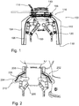
- Fig. 1 shows a gripper 100 for an industrial robot with a protective device 102 with a cover 104 and elastic traction means, such as 106.
- the protective device 102 serves to protect a person cooperating with the industrial robot in its work area from the gripper 100 and possibly a gripped workpiece.
- the protective device 102 has an annular fastening section 108 for fastening to the gripper 100.
- the gripper 100 has a connection flange 110 for connection to a corresponding connection flange of an industrial robot.
- the protective device 102 is fastened with its fastening section 108 to the gripper 100 in the vicinity of the connection flange 110.
- the sleeve 104 is slack and delimits a pressure chamber 112 that can be filled and / or evacuated.
- An air distribution channel is arranged in the fastening section 108.
- the pressure chamber 112 and the air distribution duct are connected to one another in a communicating manner.
- An air hose 114 is arranged on the fastening section 108.
- the air hose 114 is connected to the air distribution duct in a communicating manner.
- the pressure chamber 112 can be filled with air via the air hose 114 and the air distribution channel and / or air can be sucked out of the pressure chamber 112.
- the sheath 104 has a fixed end section 116, which is tightly connected to the fastening section 108, and a free end section 118.
- the elastic traction means 106 are arranged in the pressure chamber 112. In the present case, the traction means 106 are designed as rubber bands.
- the traction means 106 are each connected with one end to the fastening section 108 and with another end at the free end section 118 to the casing 104 in a tensile manner.
- the sleeve 104 has reinforcing elements, such as 120, in areas that bear against the gripper 100 when the pressure chamber 112 is filled.
- the reinforcement elements 120 are in the present case made of a plastic.
- Fig. 2 shows a gripper 200 for an industrial robot with a protective device 202 with a fillable and / or evacuable shell 204, traction means, such as 206, and actuators, such as 208.
- the traction means 206 each have one end with an actuator 208 and another end the free end section 210 is connected to the casing 204 in a tensile manner.
- the traction means 206 have a low elasticity and serve to transfer tensile forces from the actuators 208 to the casing 204.
- the actuators 208 serve to apply a traction force to the traction means 206 and each have a pneumatically actuatable piston-cylinder arrangement.
- Fig. 1 and the associated description.
- Fig. 3 shows an industrial robot 300 with a manipulator 302, a gripper 304 and a protective device 306, such as protective device 102 according to FIG Fig. 1 or protection device 202 according to Fig. 2 , when inflated.
- Fig. 4 shows the industrial robot 300 with protective device 306 in the retracted state.
- the envelope 308 is inflated and encloses the gripper 304, as in FIG Fig. 3 shown hood-like.
- the sleeve 308 is withdrawn and attached to the fastening section 310 of the protective device 306, as in FIG Fig. 4 shown, arranged folded up like a scarf.
- the sheath 308 is withdrawn when a workpiece is picked up or deposited with the aid of the gripper 304, and inflated when the manipulator 302 is moved with the gripper 304 with or without a workpiece. Retraction of the sheath 308 is supported by the traction means and, if necessary, actuators.
- FIGS. 1 and 2 as well as the associated description.
- Fig. 5 shows an industrial robot 400 with a gripper and a protective device 402 for an effector with an information technology user interface 404.
- the user interface 404 is used both for information output and for information input.
- the shell 406 has multiple chambers such as 410, 412.
- the chambers 410, 412 are separated from one another in a fluid-tight manner and form separate ones from one another Pressure rooms. In the event of a defect, in particular damage and / or leakage of individual chambers 410, 412, basic security is maintained.
- the chambers 410, 412 can be individually replaced or repaired.
- the protective device 402 has a light module for information output.
- the light module is arranged within the envelope 406.
- the sheath 406 is made of a translucent material.
- the shell 406 can be illuminated in different colors from the inside with the aid of the light module. This can be used to signal status information, a security status, an error or a required interaction, for example.
- the protective device 402 has a touchpad 408 for information output.
- the touchpad 408 is arranged on the outside of the case 406 and is firmly connected to the case 406.
- the touchpad 408 is flexible in such a way that the sleeve 406 with the touchpad 408 can be withdrawn from the effector.
- the touchpad 408 in the present case has symbols and digits.
- FIGS. 1 and 2 In addition, in particular on FIGS. 1 and 2 , on FIGS. 3 and 4 as well as the associated description.
Abstract
Description
- Die Erfindung betrifft eine Schutzvorrichtung für einen Effektor eines Manipulators, wobei die Schutzvorrichtung eine biegeschlaffe Hülle aufweist und die Hülle einen befüllbaren und/oder evakuierbaren Druckraum begrenzt. Außerdem betrifft die Erfindung eine Vorrichtung zum Manipulieren von Werkstücken, die Vorrichtung aufweisend einen Manipulator mit einem Effektor. Außerdem betrifft die Erfindung ein Verfahren zum Betätigen einer derartigen Vorrichtung.
- Aus der
DE 10 2012 007 242 A1 ist ein Überwachungssystem bekannt zur Gewährleistung einer sicheren Zusammenarbeit zwischen mindestens einem Arbeiter und mindestens einem Roboter in einem Mensch-Roboter-Kooperationssystem, welches den mindestens einen Roboter und mindestens einen Arbeitsplatz für den mindestens einen Arbeiter enthält, wobei das Überwachungssystem aufweist: eine Erkennungseinheit zum Erfassen einer Position des Arbeiters und/oder eines Bewegungsverhaltens mindestens eines Körperteils des Arbeiters; mindestens einen Überwachungssensor zum Festlegen und Überwachen mindestens eines Gefahrenbereichs um den Roboter, in welchem der Aufenthalt des Arbeiters nicht oder nur eingeschränkt erlaubt ist, und/oder zum Festlegen und Überwachen mindestens einer Begrenzung des Gefahrenbereichs sowie zur Detektion zumindest eines Bereichsübertritts des Arbeiters und/oder des Roboters in und/oder aus dem Gefahrenbereich; und eine Steuereinheit zur Verarbeitung der erfassten Position und/oder des erfassten Bewegungsverhaltens und mindestens eines gegebenenfalls detektierten Bereichsübertritts und zur Steuerung des Roboters in Abhängigkeit von der erfassten Position und/oder dem erfassten Bewegungsverhalten und dem gegebenenfalls detektierten Bereichsübertritt. - Aus der
WO 2014/008929 A1 ist ein Verfahren bekannt zum Steuern eines Roboters, welcher in einem Arbeitsmodus betreibbar ausgestaltet ist, in welchem ein Teil des Roboters mit einer Geschwindigkeit bewegt wird, bei welcher ein Verletzungsrisiko für eine Person besteht, falls die Person mit dem Teil kollidiert, wobei der Arbeitsmodus deaktiviert wird, falls durch eine Sicherungseinrichtung erkannt wird, dass die Person in einen Aktionsbereich des beweglichen Teils eindringt, mit den Schritten: durch eine Sensoreinheit der Sicherungseinrichtung Ermitteln einer Position und einer Körperhaltung der Person, während sich die Person außerhalb des Aktionsbereichs des Teils befindet; durch eine Prädiktionseinheit der Sicherungseinrichtung Ermitteln eines Aktionsbereichs der Person, welcher durch Orte definiert ist, welche von der Person aus der ermittelten Körperhaltung heraus innerhalb eines vorgegebenen Zeitintervalls voraussichtlich erreichbar sind; durch eine Kollisionsüberwachungseinheit der Sicherungseinrichtung überprüfen, ob sich der Aktionsbereich der Person und der Aktionsbereich des beweglichen Teils überschneiden und gegebenenfalls Umschalten des Roboters vom Arbeitsmodus in einen Sicherheitsmodus, in welchem zur Vermeidung einer Verletzung der Person die Geschwindigkeit des Teils reduziert ist und/oder das Teil an der Person vorbeigeführt wird. - Aus der
DE 10 2014 019 033 A1 ist ein Industrieroboter bekannt, der mit einem Menschen zusammenarbeitet und der eine Basiseinheit und eine bewegliche Einheit aufweist, die beweglich auf oder oberhalb der Basiseinheit vorgesehen ist, wobei der Roboter umfasst: ein Schutzelement, das aus einem Material mit einer Steifigkeit besteht, die niedriger als die Steifigkeiten der Basiseinheit und der beweglichen Einheit ist, wobei das Schutzelement einen Umfang von zumindest der beweglichen Einheit der Basiseinheit und die bewegliche Einheit abdeckt; und eine Erfassungseinrichtung, die zumindest auf der Basiseinheit oder der beweglichen Einheit vorgesehen ist, um eine externe Kraft zu erfassen, die durch das Schutzelement eingegeben wird. - Aus der
DE 10 2006 044 071 A1 sind ein Roboter mit einer Manipulatoreinrichtung sowie eine Roboter-Schutzeinrichtung bekannt, die die Manipulatoreinrichtung zumindest teilweise umgibt, wobei das Volumen der Schutzeinrichtung zur Anpassung an die Arbeitsbedingungen und/oder zur Dämpfung eines Aufpralls durch Zuführen bzw. Ablassen eines Fluids veränderbar ist. Die Schutzeinrichtung kann einen kompressiblen Kunststoff aufweisen und elastisch eine Kollision dämpfen. Die Schutzeinrichtung kann mit einer Halteeinrichtung, die elastische Bänder aufweist, umgeben sein. Die Schutzeinrichtung kann einen Drucksensor zum Detektieren einer Druckänderung des Fluids aufweisen. - Das Dokument
JP H09 285992 A JP H09 285992 A - Der Erfindung liegt die Aufgabe zugrunde, eine eingangs genannte Schutzvorrichtung baulich und/oder funktional zu verbessern. Außerdem liegt der Erfindung die Aufgabe zugrunde, eine eingangs genannte Vorrichtung baulich und/oder funktional zu verbessern. Außerdem liegt der Erfindung die Aufgabe zugrunde, eingangs genannte Verfahren zu verbessern.
- Die Lösung der Aufgabe erfolgt mit einer Schutzvorrichtung mit den Merkmalen des Anspruchs 1. Außerdem erfolgt die Lösung der Aufgabe mit einer Vorrichtung mit den Merkmalen des Anspruchs 3. Außerdem erfolgt die Lösung der Aufgabe mit einem Verfahren mit den Merkmalen des Anspruchs 4. Außerdem erfolgt die Lösung der Aufgabe mit einem Verfahren mit den Merkmalen des Anspruchs 5. Vorteilhafte Ausführungen und Weiterbildungen sind Gegenstand der abhängigen Ansprüche.
- Die Schutzvorrichtung kann dazu dienen, einen und/oder vor einem Effektor zu schützen. Die Schutzvorrichtung kann dazu dienen, vor einem Effektor und ein an dem Effektor befindliches Werkstück und/oder vor einem Effektor und vor einem an dem Effektor befindlichen Werkstück zu schützen. Die Schutzvorrichtung kann dazu dienen, Menschen zu schützen. Der Effektor kann zum Handhaben, Montieren und/oder Bearbeiten von Werkstücken dienen. Der Effektor kann ein Greifer sein.
- Die Hülle kann mehrere Kammern aufweisen. Die Kammern können einzeln und/oder gruppenweise voneinander fluiddicht getrennt sein. Einzelne und/oder gruppenweise voneinander fluiddicht getrennte Kammern können Druckräume bilden. Die Kammern können gruppenweise miteinander fluiddurchlässig kommunizierend verbunden sein. Zwischen den Kammern können fluiddichte Trennwände angeordnet sein. Die Kammern können einzeln oder gruppenweise austauschbar sein. Die Kammern können einzeln oder gruppenweise reparierbar sein.
- Die Benutzerschnittstelle kann zur Informationsausgabe dienen. Die Benutzerschnittstelle kann zur Informationsausgabe an eine Bedienperson dienen. Eine Information kann eine Statusinformation sein. Eine Information kann sich darauf beziehen, ob ein Werkstück gegriffen oder nicht gegriffen ist. Eine Information kann sich auf einen Sicherheitszustand beziehen. Eine Information kann sich auf einen Fehler beziehen. Eine Information kann sich auf eine erforderliche Interaktion beziehen.
- Die Benutzerschnittstelle kann ein Lichtmodul aufweisen. Das Lichtmodul kann zur Statusprojektion dienen. Das Lichtmodul kann wenigstens ein Leuchtmittel aufweisen. Das wenigstens eine Leuchtmittel kann eine LED sein. Das Lichtmodul kann eine elektrische/elektronische Steuereinrichtung aufweisen. Das Lichtmodul kann wenigstens einen elektrischen Leistungseingang aufweisen. Das Lichtmodul kann wenigstens einen elektrischen Energiespeicher aufweisen. Das Lichtmodul kann wenigstens einen elektrischen Signaleingang aufweisen. Das Lichtmodul kann wenigstens einen elektrischen Signalausgang aufweisen. Das Lichtmodul kann wenigstens ein Objektiv aufweisen.
- Die Hülle kann mithilfe des Lichtmoduls zumindest abschnittsweise beleuchtbar sein. Das Lichtmodul kann innerhalb der Hülle angeordnet sein. Das Lichtmodul kann innen an der Hülle angeordnet sein. Die Hülle kann mithilfe des Lichtmoduls von innen beleuchtbar sein. Das Lichtmodul kann außerhalb der Hülle angeordnet sein. Das Lichtmodul kann außen an der Hülle angeordnet sein. Die Hülle kann mithilfe des Lichtmoduls von außen beleuchtbar sein.
- Mithilfe des Lichtmoduls kann Licht unterschiedlicher Farbe erzeugbar sein. Mithilfe des Lichtmoduls kann Licht wechselnder Farbe erzeugbar sein. Mithilfe des Lichtmoduls kann rotes, blaues und/oder gelbes Licht erzeugbar sein. Mithilfe des Lichtmoduls können Mischfarben aus rotem, blauem und/oder gelbem Licht erzeugbar sein. Mithilfe des Lichtmoduls können zeitliche Lichtmuster erzeugbar sein. Mithilfe des Lichtmoduls kann blinkendes Licht und/oder Dauerlicht erzeugbar sein. Mithilfe des Lichtmoduls können Kommunikationszeichen darstellbar sein. Kommunikationszeichen können Grafiken und/oder Abbildungen sein.
- Die Hülle kann zumindest abschnittsweise transparent oder transluzent sein.
- Die Benutzerschnittstelle kann zur Informationseingabe dienen. Die Benutzerschnittstelle kann zur Informationseingabe an die Schutzvorrichtung dienen. Die Benutzerschnittstelle kann zur Informationseingabe an die Vorrichtung zum Manipulieren von Werkstücken dienen.
- Die Benutzerschnittstelle kann eine Tastatur, ein Touchpad und/oder ein Touchscreen aufweisen. Die Tastatur, das Touchpad und/oder das Touchscreen können/kann außenseitig an der Hülle angeordnet sein. Die Tastatur, das Touchpad und/oder das Touchscreen können/kann mit der Hülle fest verbunden sein. Die Tastatur, das Touchpad und/oder das Touchscreen können/kann flexibel sein. Die Tastatur, das Touchpad und/oder das Touchscreen können/kann biegbar sein. Die Tastatur, das Touchpad und/oder das Touchscreen können/kann faltbar sein. Die Tastatur, das Touchpad und/oder das Touchscreen können/kann mehrere Eingabeabschnitte aufweisen. Die Tastatur, das Touchpad und/oder das Touchscreen können/kann Gelenke aufweisen. Die Tastatur, das Touchpad und/oder das Touchscreen können/kann Symbole, Ziffern und/oder Buchstaben aufweisen.
- Die Schutzvorrichtung kann eine biegeschlaffe Hülle aufweisen. Die Hülle kann wenigstens einen befüllbaren und/oder evakuierbaren Druckraum begrenzen.
- Die Hülle kann einen niedrigen Elastizitätsmodul aufweisen. Die Hülle kann eine geringe Dehnsteifigkeit aufweisen. Die Hülle kann bei Kraft- und/oder Momentbeanspruchung stark verformbar sein. Die Hülle kann aus einem textilen Material hergestellt sein. Die Hülle kann aus einem Gewebe hergestellt sein. Die Hülle kann aus Polyamid hergestellt sein. Die Hülle kann eine Innenseite aufweisen. Die Innenseite kann dem Druckraum zugewandt sein. Die Hülle kann eine Außenseite aufweisen.
- Der Druckraum kann mit einem Gas, insbesondere Luft, befüllbar sein. Der Druckraum kann zumindest annähernd gasdicht, insbesondere luftdicht, sein. Die Hülle kann aufblasbar sein. Aus dem Druckraum kann Gas, insbesondere Luft, absaugbar sein. Der Druckraum kann wenigstens einen Einlass aufweisen. Der Druckraum kann wenigstens einen Auslass aufweisen. Der Druckraum kann wenigstens einen kombinierten Ein-/Auslass aufweisen.
- Die Schutzvorrichtung kann ein Beaufschlagungsmodul zum Befüllen und/oder Evakuieren des Druckraums aufweisen. Das Beaufschlagungsmodul kann eine Druckerzeugungsvorrichtung aufweisen. Die Druckerzeugungsvorrichtung kann zum Erzeugen von Über- und/oder Unterdruck dienen. Das Beaufschlagungsmodul kann eine Pumpe, insbesondere eine Hubkolbenpumpe, aufweisen. Die Pumpe kann in einem Druckbetrieb und/oder in einem Saugbetrieb betreibbar sein. Das Beaufschlagungsmodul kann wenigstens ein Ventil aufweisen. Das wenigstens eine Ventil kann elektrisch, elektromotorisch, elektromagnetisch und/oder pneumatisch betätigbar sein. Das Beaufschlagungsmodul kann eine Kontrolleinrichtung zum Kontrollieren des wenigstens einen Ventils aufweisen. Die Kontrolleinrichtung kann eine elektrische Kontrolleinrichtung sein.
- Die Hülle kann zumindest abschnittsweise elastisch sein. Die Hülle kann zumindest abschnittsweise gummielastisch sein. Die Hülle kann zumindest abschnittsweise eine vorbestimmte Elastizität aufweisen. Die Hülle kann wenigstens einen Abschnitt mit einer höheren Elastizität und wenigstens einen Abschnitt mit einer geringeren Elastizität aufweisen. Die Hülle kann zumindest abschnittsweise verstärkt sein. Die Hülle kann wenigstens ein Verstärkungselement aufweisen. Das wenigstens eine Verstärkungselement kann aus einem Kunststoff, aus einem Metall, aus Leder und/oder aus einem sonstigen Verstärkungsmaterial hergestellt sein. Das wenigstens eine Verstärkungselement kann eine plattenartige Form aufweisen. Das wenigstens eine Verstärkungselement kann eine schalenartige Form aufweisen. Das wenigstens eine Verstärkungselement kann an einer vorbestimmen Stelle angeordnet sein. Das wenigstens eine Verstärkungselement kann an einer Innenseite der Hülle angeordnet sein.
- Die Hülle kann bei befülltem Druckraum eine doppelwandige Form aufweisen. Der befüllte Druckraum kann einen ringförmigen Querschnitt aufweisen. Die Hülle kann bei befülltem Druckraum eine haubenartige Form aufweisen. Die Hülle kann bei befülltem Druckraum eine tonnenartige Form aufweisen. Die Hülle kann bei evakuiertem Druckraum eine rundschalartige Form aufweisen. Die Hülle kann einen festen Endabschnitt und einen freien Endabschnitt aufweisen. Die Hülle kann aus einem Teil hergestellt sein. Die Hülle kann mehrere miteinander verbundene Teile aufweisen.
- Die Hülle kann eine faltbare Wabenstruktur aufweisen. Die Hülle kann zumindest abschnittsweise aus Holzstoff, Zellstoff, Halbzellstoff und/oder Altpapier hergestellt sein. Die Hülle kann zumindest abschnittsweise aus Papier oder Pappe hergestellt sein.
- Das wenigstens eine erste Zugmittel kann zum Übertragen von Zugkräften dienen. Das wenigstens eine erste Zugmittel kann eine geringe Elastizität aufweisen. Das wenigstens eine erste Zugmittel kann mit einem Ende mit der Hülle zugfest verbunden sein.
- Der wenigstens eine Aktuator kann eine Kolben-Zylinder-Anordnung aufweisen. Der wenigstens eine Aktuator kann pneumatisch betätigbar sein. Der wenigstens eine Aktuator kann elektromotorisch oder elektromagnetisch betätigbar sein. Das wenigstens eine erste Zugmittel kann mit einem Ende mit dem wenigstens einen Aktuator zugfest verbunden sein.
- Das wenigstens eine erste Zugmittel kann zumindest abschnittsweise elastisch sein. Das wenigstens eine erste Zugmittel kann zumindest abschnittsweise federelastisch sein. Das wenigstens eine erste Zugmittel kann zumindest abschnittsweise gummielastisch sein. Das wenigstens eine erste Zugmittel kann zumindest abschnittsweise als elektroaktives Polymer ausgeführt sein.
- Die Schutzvorrichtung kann wenigstens ein zweites Zugmittel aufweisen, um die Hülle bei befülltem Druckraum in einer räumlich vorbestimmten Form zu stabilisieren. Das wenigstens eine zweite Zugmittel kann zum Übertragen von Zugkräften dienen. Das wenigstens eine zweite Zugmittel kann eine geringe Elastizität aufweisen. Das wenigstens eine zweite Zugmittel kann eine vorbestimmte Länge aufweisen. Das wenigstens eine zweite Zugmittel kann mit beiden Enden mit der Hülle zugfest verbunden sein.
- Die Schutzvorrichtung kann wenigstens einen Drucksensor zum Erfassen eines Drucks in dem Druckraum aufweisen. Der wenigstens eine Drucksensor kann mit der Kontrolleinrichtung zum Kontrollieren des wenigstens einen Ventils signalleitend verbunden sein.
- Die Schutzvorrichtung kann ein Befestigungsmodul und eine Hülle aufweisen. Das Befestigungsmodul kann auch als Flansch oder Airbagflansch bezeichnet werden. Die Hülle kann auch als Airbag bezeichnet werden. Das Befestigungsmodul und die Hülle können miteinander zerstörungsfrei lösbar verbunden sein. Das Befestigungsmodul und die Hülle können miteinander mithilfe einer Schnellwechselkupplung verbunden sein. Das Befestigungsmodul und die Hülle können miteinander mithilfe einer Schraubverbindung verbunden sein. Das Befestigungsmodul und die Hülle können miteinander mithilfe einer Bajonettverbindung verbunden sein. Das Befestigungsmodul und die Hülle können miteinander luftdicht verbunden sein. Das Befestigungsmodul kann eine ringartige Form aufweisen. Das Befestigungsmodul kann zur festen Anordnung an einem Manipulator, insbesondere an einem Verbindungsbereich für einen Effektor, dienen. Das Lichtmodul kann an dem Befestigungsmodul angeordnet sein.
- Die Vorrichtung kann ein Industrieroboter sein. Die Vorrichtung kann eine elektrische/elektronische Steuereinrichtung aufweisen. Die Steuereinrichtung der Vorrichtung und die Steuereinrichtung des Lichtmoduls können miteinander signalleitend verbunden sein. Der Manipulator kann wenigstens einen Armabschnitt aufweisen. Der Manipulator kann wenigstens ein Gelenk aufweisen. Der Manipulator kann bewegbar sein. Der Manipulator kann programmiert bewegbar sein. Der Manipulator kann ein Roboterarm sein. Der Manipulator kann ein Arm eines Industrieroboters sein. Der Manipulator kann ein freies Ende aufweisen. An dem freien Ende des Manipulators kann ein Anschlussabschnitt für den Effektor angeordnet sein. Der Effektor kann einen korrespondierenden Anschlussabschnitt aufweisen. Der Manipulator und der Effektor können miteinander in einem Verbindungsbereich verbunden sein. Der Manipulator kann Drehmomentsensoren aufweisen. Signale der Drehmomentsensoren können der Schutzvorrichtung zur Verfügung stehen.
- Die Schutzvorrichtung kann an dem Verbindungsbereich angeordnet sein. Die Schutzvorrichtung kann an dem Effektor verbindungsbereichsseitig angeordnet sein. Bei befülltem Druckraum kann die Hülle den Effektor zumindest annähernd vollständig umschließen. Bei befülltem Druckraum kann die Hülle den Effektor zumindest seitlich umschließen. Bei befülltem Druckraum kann die Hülle den Effektor haubenartig umschließen. Bei befülltem Druckraum kann die Hülle einen einseitig offenen Schutzraum für den Effektor bilden.
- An dem Effektor können vorgegebene Mindestradien eingehalten werden. An dem Effektor können vorgegebene Mindestradien eingehalten werden, um eine Beschädigung der Hülle zu vermeiden.
- Der Druckraum kann befüllt werden, um die Hülle aufzublasen. Der Druckraum kann evakuiert werden, um die Hülle einzuziehen. Das wenigstens eine erste Zugmittel kann freigegeben werden, wenn eine Manipulation eines Werkstücks nicht vorgesehen ist. Das wenigstens eine erste Zugmittel kann mithilfe des Aktuators mit einer Zugkraft beaufschlagt werden, wenn eine Manipulation eines Werkstücks vorgesehen ist. Das wenigstens eine erste Zugmittel kann mit einer Zugkraft beaufschlagt werden, um ein Einziehen der Hülle zu unterstützen.
- Ein Druck in dem Druckraum kann erfasst werden, um einen Druck in dem Druckraum zu kontrollieren. Der Druckraum kann weiter befüllt werden, wenn ein vorgegebener Druckwert noch nicht erreicht ist. Ein Befüllen des Druckraums kann beendet werden, wenn ein vorgegebener Druckwert erreicht wird. Wenn ein vorgegebener Druckwert erreicht wird, kann ein Freigabesignal ausgegeben werden. Das Freigabesignal kann dazu dienen, eine Bewegung des Manipulators oder eine Bewegung mit einer erhöhten Geschwindigkeit freizugeben. Ein Druck in dem Druckraum kann erfasst werden, um eine Kollision festzustellen. Eine Kollision kann festgestellt werden, wenn ein vorgegebener Druckwert überschritten wird. Wenn ein vorgegebener Druckwert überschritten wird, kann ein Fehlersignal ausgegeben werden. Das Fehlersignal kann dazu dienen, ein sofortiges Anhalten einzuleiten.
- Die Statusinformation kann sich auf ein Werkstück, die Hülle, einen Sicherheitszustand, einen Fehlerzustand und/oder eine erforderliche Interaktion beziehen. Die Statusinformation kann mithilfe des Lichtmoduls signalisiert werden.
- Die Statusinformation kann mithilfe einer vorbestimmten Farbe oder Farbkombination signalisiert werden. Die Statusinformation kann mithilfe eines vorbestimmten zeitlichen Lichtmusters signalisiert werden. Die Statusinformation kann mithilfe eines vorbestimmten Kommunikationszeichens signalisiert werden.
- Das Wechselerfordernis der Hülle kann abhängig von einer Benutzung und/oder zeitabhängig signalisiert werden. Eine Benutzung der Hülle kann ein Aufblasen und/oder Zurückziehen der Hülle beinhalten. Eine Anzahl von Benutzungsvorgängen kann gezählt werden. Ein Wechselerfordernis der Hülle kann nach einer vorbestimmten Anzahl von Benutzungsvorgängen signalisiert werden. Eine Anzahl von Benutzungsvorgängen kann mit einem vorgegebenen Grenzwert verglichen werden. Bei Überschreiten des vorgegebenen Grenzwerts kann ein Wechselerfordernis der Hülle signalisiert werden. Eine Benutzungsdauer der Hülle kann erfasst werden. Ein Wechselerfordernis der Hülle kann nach einer vorbestimmten Benutzungsdauer signalisiert werden. Eine Benutzungsdauer kann mit einem vorgegebenen Grenzwert verglichen werden. Bei Überschreiten des vorgegebenen Grenzwerts kann ein Wechselerfordernis der Hülle signalisiert werden.
- Die Hülle kann eindeutig identifizierbar sein. Die Hülle kann eindeutig identifizierbar sein, um Informationen, insbesondere Benutzungsinformationen, über die Hülle der Hülle zuzuordnen. Die Hülle kann elektronisch und/oder mechanisch identifizierbar sein. Die Hülle kann einen codierten Transponder aufweisen. Die Hülle kann einen RFID-Transponder aufweisen. Das Befestigungsmodul kann ein Lesegerät aufweisen. Das Befestigungsmodul kann zum Identifizieren der Hülle dienen. Das Befestigungsmodul kann ein RFID-Lesegerät aufweisen. Das Lichtmodul kann zum Identifizieren der Hülle dienen. Das Lichtmodul und das Befestigungsmodul können miteinander signalleitend verbunden sein.
- Zusammenfassend und mit anderen Worten dargestellt ergibt sich somit durch die Erfindung unter anderem ein Robotersicherheitsmodul mit Vakuum-Druckluft-Airbag für Roboter-Mensch-Interaktion.
- Es kann ein mit Druckluft gefüllter Airbag bereitgestellt werden. Der Airbag kann durch seine Form unterschiedlichste Endeffektoren oder Werkzeuge an einem Roboter-Tool-Center-Point voll oder teilweise umschließen. Damit können bei Kollisionen mit einem Mensch oder mit Gegenständen Verletzungen bzw. Beschädigungen verhindert oder stark verringert werden. Der Airbag kann um das Werkzeug oder auch um einen Greifer mit einem gegriffenen Werkstück herum ragen und somit harte und scharfe Kanten abdecken und einen Schutzpuffer zwischen Mensch und Werkzeug/Werkstück bilden. In Abhängigkeit eines Drucks kann ein Härtegrad eingestellt werden. Bei Klemmungen kann der Airbag als Pufferzone und/oder Schutz für den Mensch verwendet werden. Durch Ablassen von Luft kann eine Klemmung gelöst werden. Der Airbag ist derart angeordnet, dass ein Werkzeug bzw. zu fügendes Werkstück an Manipulationsstellen nicht behindert wird. In den Airbag können Seile und/oder Führungsstrukturen integriert sein. Durch Vakuum kann Luft aus dem Airbag entfernt werden. Durch Überdruck in Vakuumkammern können Zylinder in eine Richtung bewegt werden, die Führungsseile soweit nach oben ziehen, dass der Airbag aus einem Arbeitsbereich entfernt wird und eine Manipulation ohne Störungen durchgeführt werden kann.
- Das System kann in einen Flansch und einen Luftsack aufgeteilt sein. Der Luftsack kann dabei durch einen luftdichten Bajonettverschluss oder ähnliche Schnellwechselkupplungen einfach auswechselbar sein. Der Luftsack kann nach einer vorher festgelegten Anzahl von Aktivierungen und Deaktivierungen bzw. einer stärkeren Kollision einfach und schnell ausgetauscht werden.
- In einer Elektronik kann eine maximal zulässige Anzahl an Aktivierungs- und Deaktivierungsvorgängen, bis zu der eine Sicherheit des Systems gewährleistet werden kann, vorab hinterlegt, von der Elektronik gezählt und mit einem Grenzwert abgeglichen werden. Sollte dieser Grenzwert erreicht sein, so kann entweder die Elektronik die Aktivierung sperren, bis ein neuer Luftsack angebracht wurde. Hierzu kann eine Einrichtung vorgesehen sein, welche erkennt, ob ein angebrachter Luftsack noch verwendet werden darf. Beispielsweise kann dies über einen RFID-Tag im Luftsack erfolgen, welcher von der Elektronik erfasst werden kann und dem Luftsack eine eindeutige Identität zuweist. Die Elektronik kann mit dem Internet verbindbar sein und somit Zugriff auf eine externe Datenbank zum Abgleich von Daten haben. Die Elektronik kann über das Lichtmodul einem Nutzer durch eine vorbestimmte Farbkombination mitteilen, dass ab sofort eine Sicherheit nicht mehr gewährleistet wird.
- Die Druckluftzuführung kann über einen Zylinderkolben, welcher den notwendigen Druck bereitstellt, ausgeführt sein. Dieser kann bei Zurückziehen gegebenenfalls auch die Luft wieder aus dem Luftsack entfernen und diesen vakuumieren. Dabei kann das Volumen des Zylinderkolbens so ausgelegt sein, dass ein geeigneter Druck auf den Luftsack aufgebracht werden kann.
- Zum Schutz vor scharfen Kanten von Werkstück und Greifer kann eine honigwabenförmige Zellstruktur aus Papier, welche dadurch auf geringe Größe faltbar ist, um den Endeffektor angeordnet werden. Ein Öffnen und Schließen kann dabei durch einen Aktuator, beispielsweise durch einen elektromagnetischen Motor, erfolgen. Es können verschiedene Sensoriken vorgesehen sein. Eine, die zuverlässig überwacht, ob die Schutzeinrichtung vollständig geöffnet oder geschlossen ist. Und eine andere Sensorik, welche eine Kollision mit einem Menschen erkennt. Ein einfacher Austausch der sicherheitsrelevanten Komponenten durch eine Schnellwechseleinrichtung bzw. eine Überwachung der Anzahl an Aktivierung und der Abgleich mit einem Schwellwert kann erfolgen.
- Das Sicherheitsmodul kann ein Lichtmodul zur Statusprojektion und Informationsübermittlung aufweisen. Gerade bei aufgeblasenem Airbag kann dieses Lichtmodul den Airbag in verschiedenen Farben leuchten lassen. Farben können bspw. sein Rot, Blau, Gelb, Grün, sowie Mischungen der Farben. Das Licht kann zudem blinken oder auch dauerhaft leuchten. Statusinformation können sein: Werkstück gegriffen oder nicht, Sicherheit gewährleistet oder nicht, Fehlfunktion, warten auf Interaktion. Ferner ist es denkbar, die gesamte Oberfläche des Airbags als Projektionsfläche zu nutzen, um hier Graphiken, Abbildungen oder dergleichen darzustellen. Zusätzlich kann im Airbag ein taktiles Interface untergebracht sein. Dieses taktile Interface ist vorzugsweise biegbar, sodass das Interface bei deaktiviertem Airbag dem Zusammenziehen des Airbags folgen kann. Das taktile Interface kann dabei in verschiedene Zonen unterteilt bzw. aus mehreren taktilen Knöpfen ausgebildet sein, sodass verschiedene Kommandos vom Menschen an den Roboter über das taktile Interface übertragen werden können. Der Mensch kann dazu eine der Tasten, repräsentiert durch die taktile Sensorik auf dem aufgeblasenen Airbag, drücken. Diese Tasten können verschiedene Roboter-, Airbag- oder auch Greiferfunktionen symbolisieren aber auch Zahlenfelder zur Eingabe von Variablen.
- Ein Robotersicherheitssystem kann einen Airbag aufweisen, welcher zusätzlich über ein Lichtmodul in verschiedenen Farben leuchten kann. Diese Farben können verschiedene Statusinformationen des Greifers suggerieren. Beispielsweise ob der Greifer bei aktiviertem Airbag ein Werkstück gegriffen hat oder nicht oder ob es eine Fehlfunktion des Airbags gibt. Ferner kann ein "Warten auf Interaktion" oder die Statusinformation "Sicherheit gewährleistet" über das Lichtmodul dem Benutzer mitgeteilt werden. Der Airbag kann mit einer flexiblen taktilen Sensorik ausgestattet sein, welche bei Drücken verschiedene Roboter-, Airbag- oder Greiferfunktionalitäten realisiert. Beispielsweise kann der Greifer über das Tastenfeld geöffnet oder geschlossen werden, der Airbag deaktiviert werden, der Roboter kalibriert werden, eine Trajektorie eingelernt werden oder der Roboter in den Zero-Gravity-Modus geschaltet werden.
- Das Lichtmodul kann LEDs und eine Elektronik aufweisen. Das Lichtmodul kann in einem Airbagflansch mit untergebracht sein. Beispielsweise kann ein grün angestrahlter Airbag bedeuten, dass die Sicherheit des gesamten Robotersystems bestehend aus Roboter und Sicherheitsmodul gewährleistet ist, der Roboter kann in einem Mensch-Maschine-Kollaborationsszenario betrieben werden und der Mensch darf sich im Arbeitsraum aufhalten, ohne dass der Roboter anhält. Im Gegensatz dazu kann ein rot angestrahltes Sicherheitsmodul bedeuten, dass die Sicherheit nicht gewährleistet ist und der Mensch sich nicht im Arbeitsraum aufhalten darf, sonst stoppt der Roboter. Dies ist beispielsweise denkbar, falls der Roboter in verschiedenen Geschwindigkeiten betrieben wird. Rot blinkend wiederum kann einem Menschen suggerieren, dass der Roboter sich in einem Fehlerstatus befindet und aufgrund eines Defekts ausgeschaltet wurde. Zusätzlich kann eine Differenzierung zwischen dauerhaft grün leuchtend und grün blinkend dem Benutzer mitteilen, ob der Roboter ein Werkstück gegriffen hat oder nicht. Also ob er gerade mit oder ohne Werkstück verfährt.
- Der Roboter des Robotersystems kann mit einer Drehmomentensensorik ausgestattet sein, welche eine Interaktion mit dem Menschen zulässt, sodass einem handgeführten Roboter eine Trajektorie einprogrammiert werden kann. Dabei kann ein blaues Licht dem Menschen mitteilen, dass der Roboter auf eine Interaktion, beispielsweise das Einlernen einer Trajektorie oder der Eingabe eines Kommandos, über die Benutzerschnittstelle wartet.
- Die Benutzerschnittstelle kann mit einem Tastenfeld bestehend aus x Tasten ausgeführt sein. Die Tasten können beispielsweise zum Schalten eines Zero-Gravity-Modus, einer Roboterkalibration, ein Einlernen einer Trajektorie, ein Öffnen und Schließen eines Greifers sowie einer Deaktivierung des schützenden Airbags beim Aufzeichnen eines Bewegungsablaufes dienen. Die Elektronik dazu kann in einem Airbagflansch untergebracht sein. Der Airbag kann für das Drücken der Tasten aufgeblasen sein. Bei Drücken der Zero-Gravity-Modus-Taste kann der Roboter im Anschluss nachgiebig mit der Hand rumgeführt werden. Bei Drücken der Roboterkalibrationstaste kann dem Menschen beispielsweise durch blaues Blinken suggeriert werden, dass er den Roboter im Anschluss nicht berühren darf, da dieser sich nun selber kalibriert. Ein Sensor-Offsets kann in dieser Phase bestimmt werden. Nach Drücken der Taste zum Einlernen einer Trajektorie kann der Roboter im Anschluss rumgeführt werden und die entsprechende Trajektorie wird eingelernt und abgespeichert. Bei Drücken der Greifertaste kann sich der Greifer öffnen bzw. schließen, je nachdem in welchem Status er sich gerade befindet. Nach Drücken der Airbag-Deaktivierungstaste kann der Airbag deaktiviert werden.
- Mit der Erfindung wird eine Sicherheit erhöht. Ein Verletzungsrisiko wird reduziert. Ein Beschädigungsrisiko wird reduziert. Sich überschneidende Arbeitsbereiche Mensch/Roboter werden ermöglicht. Eine Arbeitsgeschwindigkeit ist erhöhbar. Ein Aufwand, wie Kosten-, Bau-, Sensorik- und/oder Rechenaufwand, wird reduziert. Fehlauslösungen von Schutzsystemen werden vermieden. Es wird ein Schutz vor einem Effektor ermöglicht. Es wird ein Schutz vor einem Effektor und einem an dem Effektor befindlichen Werkstück ermöglicht. Eine Mensch-Roboter-Kollaboration wird verbessert. Auch bei geschütztem Effektor kann ein Effektorstatus signalisiert werden. Eine Produktion wird verbessert. Ein Kollisionsschutz ist auch bei einem Defekt einer Kammer gegeben. Bei einem Defekt einer Kammer kann eine Reparatur vereinfacht erfolgen. Die Druckräume der Hülle können voneinander unabhängig befüllbar und/oder evakuierbar sein.
- Nachfolgend werden Ausführungsbeispiele der Erfindung unter Bezugnahme auf Figuren näher beschrieben. Aus dieser Beschreibung ergeben sich weitere Merkmale und Vorteile. Konkrete Merkmale dieser Ausführungsbeispiele können allgemeine Merkmale der Erfindung darstellen. Mit anderen Merkmalen verbundene Merkmale dieser Ausführungsbeispiele können auch einzelne Merkmale der Erfindung darstellen.
- Es zeigen schematisch und beispielhaft:
- Fig. 1
- einen Greifer für einen Industrieroboter mit einer Schutzvorrichtung mit einer Hülle und elastischen Zugmitteln,
- Fig. 2
- einen Greifer für einen Industrieroboter mit einer Schutzvorrichtung mit einer Hülle, Zugmitteln und Aktuatoren,
- Fig. 3
- einen Industrieroboter mit einem Greifer und einer Schutzvorrichtung in aufgeblasenem Zustand,
- Fig. 4
- einen Industrieroboter mit einem Greifer und einer Schutzvorrichtung in zurückgezogenem Zustand und
- Fig. 5
- einen Industrieroboter mit einem Greifer und einer Schutzvorrichtung mit einer informationstechnischen Benutzerschnittstelle.
-
Fig. 1 zeigt einen Greifer 100 für einen Industrieroboter mit einer Schutzvorrichtung 102 mit einer Hülle 104 und elastischen Zugmitteln, wie 106. Die Schutzvorrichtung 102 dient dazu, einen mit dem Industrieroboter in dessen Arbeitsbereich kooperierenden Menschen vor dem Greifer 100 und gegebenenfalls einem gegriffenen Werkstück zu schützen. - Die Schutzvorrichtung 102 weist einen ringförmigen Befestigungsabschnitt 108 zur Befestigung an dem Greifer 100 auf. Der Greifer 100 weist einen Anschlussflansch 110 zur Verbindung mit einem korrespondierenden Anschlussflansch eines Industrieroboters auf. Die Schutzvorrichtung 102 ist mit ihrem Befestigungsabschnitt 108 an dem Greifer 100 in der Nähe des Anschlussflanschs 110 befestigt.
- Die Hülle 104 ist biegeschlaff und begrenzt einen befüllbaren und/oder evakuierbaren Druckraum 112. In dem Befestigungsabschnitt 108 ist ein Luftverteilkanal angeordnet. Der Druckraum 112 und der Luftverteilkanal sind miteinander kommunizierend verbunden. An dem Befestigungsabschnitt 108 ist ein Luftschlauch 114 angeordnet. Der Luftschlauch 114 ist mit dem Luftverteilkanal kommunizierend verbunden. Über den Luftschlauch 114 und den Luftverteilkanal kann der Druckraum 112 mit Luft befüllt werden und/oder kann aus dem Druckraum 112 Luft abgesaugt werden.
- Die Hülle 104 weist einen festen, mit dem Befestigungsabschnitt 108 dicht verbundenen Endabschnitt 116 und einen freien Endabschnitt 118 auf. Die elastischen Zugmittel 106 sind in dem Druckraum 112 angeordnet. Vorliegend sind die Zugmittel 106 als Gummibänder ausgeführt. Die Zugmittel 106 sind jeweils mit einem Ende mit dem Befestigungsabschnitt 108 und mit einem anderen Ende an dem freien Endabschnitt 118 mit der Hülle 104 zugfest verbunden. An Bereichen, die bei befülltem Druckraum 112 an dem Greifer 100 anliegen, weist die Hülle 104 Verstärkungselemente, wie 120, auf. Die Verstärkungselemente 120 sind vorliegend aus einem Kunststoff hergestellt.
-
Fig. 2 zeigt einen Greifer 200 für einen Industrieroboter mit einer Schutzvorrichtung 202 mit einer befüllbaren und/oder evakuierbaren Hülle 204, Zugmitteln, wie 206, und Aktuatoren, wie 208. Die Zugmittel 206 sind jeweils mit einem Ende mit einem Aktuator 208 und mit einem anderen Ende an dem freien Endabschnitt 210 mit der Hülle 204 zugfest verbunden. Vorliegend weisen die Zugmittel 206 eine geringe Elastizität auf und dienen zum Übertragen von Zugkräften von den Aktuatoren 208 auf die Hülle 204. Die Aktuatoren 208 dienen zum Beaufschlagen der Zugmittel 206 mit einer Zugkraft und weisen jeweils eine pneumatisch betätigbare Kolben-Zylinder-Anordnung auf. Im Übrigen wird ergänzend insbesondere aufFig. 1 und die zugehörige Beschreibung verwiesen. -
Fig. 3 zeigt einen Industrieroboter 300 mit einem Manipulator 302, einem Greifer 304 und einer Schutzvorrichtung 306, wie Schutzvorrichtung 102 gemäßFig. 1 oder Schutzvorrichtung 202 gemäßFig. 2 , in aufgeblasenem Zustand.Fig. 4 zeigt den Industrieroboter 300 mit Schutzvorrichtung 306 in zurückgezogenem Zustand. Bei befülltem Druckraum ist die Hülle 308 aufgeblasen und umschließt den Greifer 304, wie inFig. 3 gezeigt, haubenartig. Bei evakuiertem Druckraum ist die Hülle 308 zurückgezogen und an dem Befestigungsabschnitt 310 der Schutzvorrichtung 306, wie inFig. 4 gezeigt, rundschalartig zusammengefaltet angeordnet. Bei einem Betrieb des Industrieroboters 300 wird die Hülle 308 zurückgezogen, wenn mithilfe des Greifers 304 ein Werkstück aufgenommen oder abgelegt wird, und aufgeblasen, wenn der Manipulator 302 mit dem Greifer 304 mit oder ohne Werkstück bewegt wird. Ein Zurückziehen der Hülle 308 wird durch die Zugmittel sowie gegebenenfalls Aktuatoren unterstützt. Im Übrigen wird ergänzend insbesondere aufFig. 1 und Fig. 2 sowie die zugehörige Beschreibung verwiesen. -
Fig. 5 zeigt einen Industrieroboter 400 mit einem Greifer und einer Schutzvorrichtung 402 für einen Effektor mit einer informationstechnischen Benutzerschnittstelle 404. Die Benutzerschnittstelle 404 dient sowohl zur Informationsausgabe als auch zur Informationseingabe. - Die Hülle 406 weist mehrere Kammern, wie 410, 412, auf. Die Kammern 410, 412 sind voneinander fluiddicht getrennt und bilden voneinander getrennte Druckräume. Bei einem Defekt, insbesondere Beschädigung und/oder Undichtigkeit einzelner Kammern 410, 412 bleibt eine Grundsicherheit erhalten. Die Kammern 410, 412 einzeln ausgetauscht oder repariert werden.
- Zur Informationsausgabe weist die Schutzvorrichtung 402 ein Lichtmodul auf. Das Lichtmodul ist innerhalb der Hülle 406 angeordnet. Die Hülle 406 ist aus einem transluzenten Material hergestellt. Die Hülle 406 ist mithilfe des Lichtmoduls von innen unterschiedlich farbig beleuchtbar. Damit können beispielsweise Statusinformationen, ein Sicherheitszustand, ein Fehler oder eine erforderliche Interaktion signalisiert werden.
- Zur Informationsausgabe weist die Schutzvorrichtung 402 vorliegend ein Touchpad 408 auf. Das Touchpad 408 ist außenseitig an der Hülle 406 angeordnet und mit der Hülle 406 fest verbunden. Das Touchpad 408 ist derart flexibel, dass die Hülle 406 mit dem Touchpad 408 von dem Effektor zurückgezogen werden kann. Das Touchpad 408 weist vorliegend Symbole und Ziffern auf.
- Im Übrigen wird ergänzend insbesondere auf
Fig. 1 und Fig. 2 , aufFig. 3 und Fig. 4 sowie die zugehörige Beschreibung verwiesen. -
- 100
- Effektor, Greifer
- 102
- Schutzvorrichtung
- 104
- Hülle
- 106
- Zugmittel
- 108
- Befestigungsabschnitt
- 110
- Anschlussflansch
- 112
- Druckraum
- 114
- Luftschlauch
- 116
- Endabschnitt
- 118
- Endabschnitt
- 120
- Verstärkungselement
- 200
- Effektor, Greifer
- 202
- Schutzvorrichtung
- 204
- Hülle
- 206
- Zugmittel
- 208
- Aktuator
- 210
- Endabschnitt
- 300
- Industrieroboter
- 302
- Manipulator
- 304
- Effektor, Greifer
- 306
- Schutzvorrichtung
- 308
- Hülle
- 310
- Befestigungsabschnitt
- 400
- Industrieroboter
- 402
- Schutzvorrichtung
- 404
- Benutzerschnittstelle
- 406
- Hülle
- 408
- Touchpad
- 410
- Kammer
- 412
- Kammer
Claims (5)
- Schutzvorrichtung (102, 202, 306, 402) für einen Effektor (100, 200, 304) eines Manipulators (302), wobei die Schutzvorrichtung (102, 202, 306, 402) eine biegeschlaffe Hülle (104, 204, 308, 406) aufweist und die Hülle (104, 204, 308, 406) einen befüllbaren und/oder evakuierbaren Druckraum (112) begrenzt, dadurch gekennzeichnet, dass die Schutzvorrichtung (102, 202, 306, 402) wenigstens ein erstes Zugmittel (106, 206) zum Zurückziehen der Hülle (104, 204, 308, 406) und wenigstens einen Aktuator (208) zum Beaufschlagen des wenigstens einen ersten Zugmittels (206) mit einer Zugkraft aufweist.
- Schutzvorrichtung (102, 202, 306, 402) nach Anspruch 1, dadurch gekennzeichnet, dass die Schutzvorrichtung (102, 202, 306, 402) ein Befestigungsmodul und eine Hülle (104, 204, 308, 406) aufweist und das Befestigungsmodul und die Hülle (104, 204, 308, 406) miteinander zerstörungsfrei lösbar verbunden sind.
- Vorrichtung (300) zum Manipulieren von Werkstücken, die Vorrichtung aufweisend einen Manipulator (302) mit einem Effektor (100, 200, 304), dadurch gekennzeichnet, dass die Vorrichtung (300) eine Schutzvorrichtung (102, 202, 306) nach wenigstens einem der vorhergehenden Ansprüche aufweist.
- Verfahren zum Betätigen einer Vorrichtung (300) nach Anspruch 3, dadurch gekennzeichnet, dass der wenigstens eine Druckraum (112) befüllt und das wenigstens eine erste Zugmittel (106, 206) freigegeben wird, wenn eine Manipulation eines Werkstücks nicht vorgesehen ist und/oder der wenigstens eine Druckraum (112) evakuiert und das wenigstens eine erste Zugmittel (106, 206) mithilfe des Aktuators mit einer Zugkraft beaufschlagt wird, wenn eine Manipulation eines Werkstücks vorgesehen ist.
- Verfahren zum Betätigen einer Vorrichtung (300) nach Anspruch 3, dadurch gekennzeichnet, dass eine Statusinformation signalisiert wird.
Applications Claiming Priority (3)
| Application Number | Priority Date | Filing Date | Title |
|---|---|---|---|
| DE102016104940.9A DE102016104940A1 (de) | 2016-03-17 | 2016-03-17 | Schutzvorrichtung für einen Effektor eines Manipulators, Vorrichtung zum Manipulieren von Werkstücken und Verfahren zum Betätigen einer Vorrichtung zum Manipulieren von Werkstücken |
| EP17711641.5A EP3429807B1 (de) | 2016-03-17 | 2017-03-16 | Schutzvorrichtung für einen effektor eines manipulators |
| PCT/EP2017/056295 WO2017158120A1 (de) | 2016-03-17 | 2017-03-16 | Schutzvorrichtung für einen effektor eines manipulators, vorrichtung zum manipulieren von werkstücken und verfahren zum betätigen einer vorrichtung zum manipulieren von werkstücken |
Related Parent Applications (2)
| Application Number | Title | Priority Date | Filing Date |
|---|---|---|---|
| EP17711641.5A Division EP3429807B1 (de) | 2016-03-17 | 2017-03-16 | Schutzvorrichtung für einen effektor eines manipulators |
| EP17711641.5A Division-Into EP3429807B1 (de) | 2016-03-17 | 2017-03-16 | Schutzvorrichtung für einen effektor eines manipulators |
Publications (2)
| Publication Number | Publication Date |
|---|---|
| EP3733362A1 true EP3733362A1 (de) | 2020-11-04 |
| EP3733362B1 EP3733362B1 (de) | 2023-06-07 |
Family
ID=58358600
Family Applications (2)
| Application Number | Title | Priority Date | Filing Date |
|---|---|---|---|
| EP17711641.5A Active EP3429807B1 (de) | 2016-03-17 | 2017-03-16 | Schutzvorrichtung für einen effektor eines manipulators |
| EP20172011.7A Active EP3733362B1 (de) | 2016-03-17 | 2017-03-16 | Schutzvorrichtung für einen effektor eines manipulators, vorrichtung zum manipulieren von werkstücken und verfahren zum betätigen einer vorrichtung zum manipulieren von werkstücken |
Family Applications Before (1)
| Application Number | Title | Priority Date | Filing Date |
|---|---|---|---|
| EP17711641.5A Active EP3429807B1 (de) | 2016-03-17 | 2017-03-16 | Schutzvorrichtung für einen effektor eines manipulators |
Country Status (5)
| Country | Link |
|---|---|
| US (1) | US11498226B2 (de) |
| EP (2) | EP3429807B1 (de) |
| CN (1) | CN108778643B (de) |
| DE (1) | DE102016104940A1 (de) |
| WO (1) | WO2017158120A1 (de) |
Families Citing this family (23)
| Publication number | Priority date | Publication date | Assignee | Title |
|---|---|---|---|---|
| AT516097B1 (de) * | 2014-07-03 | 2016-09-15 | Blue Danube Robotics Gmbh | Schutzverfahren und Schutzvorrichtung für Handhabungsgerät |
| DE102017108618B4 (de) * | 2017-04-21 | 2021-08-05 | Deutsches Zentrum für Luft- und Raumfahrt e.V. | Verfahren zum Betätigen eines Roboters |
| USD873877S1 (en) * | 2017-06-21 | 2020-01-28 | Deutsches Zentrum für Luft- und Raumfahrt e.V. | Robot airbag |
| ES2760947T3 (es) | 2017-06-23 | 2020-05-18 | Comau Spa | Conjunto funcional para una máquina industrial, en concreto para un robot, que incluye una unidad funcional equipada con una cubierta de seguridad |
| EP3427904B1 (de) * | 2017-07-13 | 2020-06-10 | Siemens Aktiengesellschaft | Anordnung mit einem manipulator und einer begrenzungseinrichtung zur begrenzung des arbeitsbereichs |
| US10137580B1 (en) * | 2017-09-15 | 2018-11-27 | Honda Motor Co., Ltd. | Systems and methods for robotic arm guard assemblies |
| USD863388S1 (en) * | 2017-12-20 | 2019-10-15 | Deutsches Zentrum für Luft- und Raumfahrt e.V. | Robot airbag |
| USD901694S1 (en) | 2018-01-17 | 2020-11-10 | Auris Health, Inc. | Instrument handle |
| USD873878S1 (en) * | 2018-01-17 | 2020-01-28 | Auris Health, Inc. | Robotic arm |
| JP7156865B2 (ja) * | 2018-08-30 | 2022-10-19 | 川崎重工業株式会社 | 緩衝装置及びそれを備えるロボット |
| DE102018122703A1 (de) * | 2018-09-17 | 2020-03-19 | E. Zoller Gmbh & Co. Kg | Greifervorrichtung mit einer Schutzeinheit |
| HU231104B1 (hu) * | 2018-10-11 | 2020-09-28 | B & O Kft. | Biztonsági burkolattal ellátott végeffektor szerkezet és eljárás a szerkezet alkalmazására |
| NL2022319B1 (en) * | 2018-12-28 | 2020-07-23 | Bollegraaf Patents And Brands B V | Suction unit for a robotic sorter |
| CN109732637A (zh) * | 2019-03-12 | 2019-05-10 | 哈工大机器人(山东)智能装备研究院 | 一种磁流体模块化机械夹手及工作方法 |
| JP7293844B2 (ja) * | 2019-04-25 | 2023-06-20 | セイコーエプソン株式会社 | ロボット |
| US20230001587A1 (en) * | 2019-12-05 | 2023-01-05 | Alexander Zak | Method and setup for fenceless robotics |
| CN111890406B (zh) * | 2020-08-07 | 2021-09-24 | 江苏昱博自动化设备有限公司 | 一种助力机械手用抱夹式夹具 |
| USD1009111S1 (en) * | 2020-12-15 | 2023-12-26 | Deutsches Zentrum für Luft- und Raumfahrt e.V. | Gripper jaw |
| EP4173780A1 (de) | 2021-10-29 | 2023-05-03 | Deutsches Zentrum für Luft- und Raumfahrt e.V. | Rückziehvorrichtung für eine zwischen einer aktivform und einer deaktivform verformbare hülle, funktionsvorrichtung mit einer zwischen einer aktivform und einer deaktivform verformbaren hülle und verfahren zum betreiben einer funktionsvorrichtung |
| DE102021128397A1 (de) | 2021-10-29 | 2023-05-04 | Deutsches Zentrum für Luft- und Raumfahrt e.V. | Rückziehvorrichtung für eine befüllbare und/oder evakuierbare biegeschlaffe Hülle, Funktionsvorrichtung mit einer befüllbaren und/oder evakuierbaren biegeschlaffen Hülle und Verfahren zum Betätigen einer Funktionsvorrichtung |
| DE202022106663U1 (de) | 2022-11-29 | 2023-04-26 | Deutsches Zentrum für Luft- und Raumfahrt e.V. | Schutzvorrichtung für einen Effektor |
| CN116277160B (zh) * | 2023-05-18 | 2023-08-29 | 深圳市大族机器人有限公司 | 一种防爆型多轴机器人 |
| CN116945139B (zh) * | 2023-09-21 | 2024-01-26 | 连云港市东堡旋耕机械有限公司 | 一种开梗机加工用机械臂 |
Citations (11)
| Publication number | Priority date | Publication date | Assignee | Title |
|---|---|---|---|---|
| JPS6339786A (ja) * | 1986-08-05 | 1988-02-20 | 松下電器産業株式会社 | 工業用ロボツトの安全装置 |
| JPH09285992A (ja) | 1996-04-22 | 1997-11-04 | Yoshisuke Ueno | ロボットの安全装置 |
| DE102006044071A1 (de) | 2006-09-20 | 2008-04-03 | Deutsches Zentrum für Luft- und Raumfahrt e.V. | Roboter sowie Roboter-Schutzeinrichtung |
| DE102007062245A1 (de) * | 2007-12-21 | 2009-06-25 | Robert Bosch Gmbh | Kollisionsdetektionsvorrichtung sowie Handhabungsgerät |
| DE102012007242A1 (de) | 2012-03-09 | 2013-09-12 | Fraunhofer-Gesellschaft zur Förderung der angewandten Forschung e.V. | Vorrichtung und Verfahren zur sicheren Mensch-Roboter-Kooperation |
| WO2014008929A1 (de) | 2012-07-10 | 2014-01-16 | Siemens Aktiengesellschaft | Roboteranordnung und verfahren zum steuern eines roboters |
| DE102012217764A1 (de) * | 2012-09-28 | 2014-06-12 | Bayerische Motoren Werke Aktiengesellschaft | Werkzeugschutzvorrichtung |
| DE202013105501U1 (de) * | 2013-12-03 | 2015-03-03 | Daimler Ag | Arbeitsvorrichtung |
| DE102014019033A1 (de) | 2013-12-25 | 2015-06-25 | Fanuc Corporation | Industrieroboter, der mit einem Menschen zusammenarbeitet und ein Schutzelement umfasst |
| DE102015005799A1 (de) * | 2015-05-06 | 2015-12-03 | Daimler Ag | Hülle für einen Roboter |
| DE102014221645A1 (de) * | 2014-10-24 | 2016-04-28 | Kuka Systems Gmbh | Flexibler Werkzeugschutz zum Einsatz mit einem Manipulator |
Family Cites Families (20)
| Publication number | Priority date | Publication date | Assignee | Title |
|---|---|---|---|---|
| US3499641A (en) * | 1967-10-02 | 1970-03-10 | Collins Radio Co | Fluid pressure actuated diaphragm workpiece clamping device |
| US3800890A (en) * | 1973-02-15 | 1974-04-02 | Ingersoll Rand Co | Dust control system |
| DE2437735B2 (de) * | 1974-08-06 | 1976-06-24 | Kernforschungsanlage Jülich GmbH, 517OJülich | Manipulator fuer bewegungen von in einem hochvakuumraum angeordneten gegenstaenden |
| US4523100A (en) * | 1982-08-11 | 1985-06-11 | R & D Associates | Optical vernier positioning for robot arm |
| DE9208980U1 (de) * | 1992-07-04 | 1993-11-04 | Kuka Schweissanlagen & Roboter | Überlastsicherung für eine Werkzeughalterung von Manipulatoren |
| US5653561A (en) * | 1993-07-23 | 1997-08-05 | May; Robert | Swarf boot |
| JPH1029191A (ja) * | 1996-07-11 | 1998-02-03 | Toyota Motor Corp | ロボット装置 |
| US6690208B2 (en) | 2002-02-23 | 2004-02-10 | Ati Industrial Automation, Inc. | Robot crash protector |
| JP2005231010A (ja) | 2004-02-23 | 2005-09-02 | Fanuc Ltd | 表示装置 |
| JP2006187854A (ja) * | 2004-12-30 | 2006-07-20 | Jong Oh Kim | 携帯型穿孔機 |
| CN100335241C (zh) * | 2005-06-13 | 2007-09-05 | 西安思源职业学院 | 全气动组合式多功能工业机械手 |
| EP1810795A1 (de) * | 2006-01-19 | 2007-07-25 | Abb Ab | Sicherheitsvorrichtung für einen Industrieroboter mit elastischem, dichtem, ein Fluid oder Gas enthaltendem Beutel |
| DE102008019021A1 (de) * | 2008-04-15 | 2009-10-29 | Volkswagen Ag | Vorrichtung zum Schutz von Robotern vor Verschmutzung und/oder Beschädigung |
| US8529170B2 (en) * | 2010-08-25 | 2013-09-10 | Ernest Everington, JR. | Retractable drill mounted dust collector |
| CN202964522U (zh) * | 2012-11-23 | 2013-06-05 | 綦江齿轮传动有限公司 | 半自动装配机械手 |
| DE102013020137A1 (de) | 2013-12-06 | 2015-06-11 | Daimler Ag | Arbeitsstation, insbesondere zum Herstellen eines Kraftwagens, sowie Verfahren zum Betreiben einer Arbeitsstation |
| JP6440385B2 (ja) * | 2014-06-10 | 2018-12-19 | キヤノン株式会社 | ロボットアーム、表示装置およびロボットシステム |
| CN204658463U (zh) | 2014-12-19 | 2015-09-23 | 库卡罗伯特有限公司 | 与机器人一起使用的安全系统 |
| CN106272565A (zh) * | 2016-09-27 | 2017-01-04 | 昆山穿山甲机器人有限公司 | 机器人防护装置 |
| US10328530B2 (en) * | 2016-09-27 | 2019-06-25 | The Boeing Company | Flexible and local laser shroud |
-
2016
- 2016-03-17 DE DE102016104940.9A patent/DE102016104940A1/de not_active Withdrawn
-
2017
- 2017-03-16 EP EP17711641.5A patent/EP3429807B1/de active Active
- 2017-03-16 WO PCT/EP2017/056295 patent/WO2017158120A1/de active Application Filing
- 2017-03-16 CN CN201780017906.6A patent/CN108778643B/zh active Active
- 2017-03-16 EP EP20172011.7A patent/EP3733362B1/de active Active
- 2017-03-16 US US16/085,783 patent/US11498226B2/en active Active
Patent Citations (11)
| Publication number | Priority date | Publication date | Assignee | Title |
|---|---|---|---|---|
| JPS6339786A (ja) * | 1986-08-05 | 1988-02-20 | 松下電器産業株式会社 | 工業用ロボツトの安全装置 |
| JPH09285992A (ja) | 1996-04-22 | 1997-11-04 | Yoshisuke Ueno | ロボットの安全装置 |
| DE102006044071A1 (de) | 2006-09-20 | 2008-04-03 | Deutsches Zentrum für Luft- und Raumfahrt e.V. | Roboter sowie Roboter-Schutzeinrichtung |
| DE102007062245A1 (de) * | 2007-12-21 | 2009-06-25 | Robert Bosch Gmbh | Kollisionsdetektionsvorrichtung sowie Handhabungsgerät |
| DE102012007242A1 (de) | 2012-03-09 | 2013-09-12 | Fraunhofer-Gesellschaft zur Förderung der angewandten Forschung e.V. | Vorrichtung und Verfahren zur sicheren Mensch-Roboter-Kooperation |
| WO2014008929A1 (de) | 2012-07-10 | 2014-01-16 | Siemens Aktiengesellschaft | Roboteranordnung und verfahren zum steuern eines roboters |
| DE102012217764A1 (de) * | 2012-09-28 | 2014-06-12 | Bayerische Motoren Werke Aktiengesellschaft | Werkzeugschutzvorrichtung |
| DE202013105501U1 (de) * | 2013-12-03 | 2015-03-03 | Daimler Ag | Arbeitsvorrichtung |
| DE102014019033A1 (de) | 2013-12-25 | 2015-06-25 | Fanuc Corporation | Industrieroboter, der mit einem Menschen zusammenarbeitet und ein Schutzelement umfasst |
| DE102014221645A1 (de) * | 2014-10-24 | 2016-04-28 | Kuka Systems Gmbh | Flexibler Werkzeugschutz zum Einsatz mit einem Manipulator |
| DE102015005799A1 (de) * | 2015-05-06 | 2015-12-03 | Daimler Ag | Hülle für einen Roboter |
Also Published As
| Publication number | Publication date |
|---|---|
| CN108778643B (zh) | 2023-05-30 |
| EP3429807A1 (de) | 2019-01-23 |
| CN108778643A (zh) | 2018-11-09 |
| US20190047160A1 (en) | 2019-02-14 |
| US11498226B2 (en) | 2022-11-15 |
| DE102016104940A1 (de) | 2017-09-21 |
| EP3733362B1 (de) | 2023-06-07 |
| EP3429807B1 (de) | 2020-10-28 |
| WO2017158120A1 (de) | 2017-09-21 |
Similar Documents
| Publication | Publication Date | Title |
|---|---|---|
| EP3429807B1 (de) | Schutzvorrichtung für einen effektor eines manipulators | |
| EP3243608B1 (de) | Verfahren zur überwachung von funktionszuständen eines druckangetriebenen aktors und druckantreibbarer aktor | |
| EP2016290B1 (de) | Verfahren zum beaufschlagen eines arbeitszylinders, steuerung dafür, arbeitszylinder und verwendung desselben | |
| DE102006044071B4 (de) | Roboter sowie Roboter-Schutzeinrichtung | |
| DE102015005908A1 (de) | System zum Transportieren eines Werkstücks mit einer Funktion zur Überwachung einer externen Kraft | |
| WO2017182567A1 (de) | Endeffektor-vorrichtung | |
| DE102015220517A1 (de) | MRK-System und Verfahren zum Steueren eines MRK-Systems | |
| DE102014109262A1 (de) | Umsetzvorrichtung zum Ansaugen und Umsetzen eines Objekts | |
| DE102014107642A1 (de) | Adaptereinrichtung | |
| EP3087022B1 (de) | Arbeitsvorrichtung | |
| DE202014104509U1 (de) | Schmiedehammer | |
| DE102017108618B4 (de) | Verfahren zum Betätigen eines Roboters | |
| DE102018127921B4 (de) | Roboter und Verfahren zur Bestimmung eines Bewegungsraums mittels eines Roboters | |
| DE4405648C2 (de) | Anordnung zur Prozeßüberwachung bei fluidisch betriebenen Eintreibegeräten | |
| EP3600796B1 (de) | Endeffektor mit verschiebbarer schutzhülse zur werkstückbearbeitung und robotersystem mit einem endeffektor | |
| DE102017211580B4 (de) | Universeller endeffektor für einen manipulator | |
| EP1166918B1 (de) | Nietsetzgerät | |
| DE102019202898A1 (de) | Antriebssystem | |
| DE202019102610U1 (de) | Greifervorrichtung | |
| DE102016221861A1 (de) | Einrichtung und Verfahren zur Einwirkung auf Gegenstände | |
| DE102010022095A1 (de) | Sicherheitsvorrichtung zur Verhinderung von Unfällen mit Personenschäden durch Maschinen | |
| DE2623013A1 (de) | Sprenggeraet mit im abstand vom sprengwerkzeug befindlichem druckluft- hydraulik-antrieb | |
| DE202008001795U1 (de) | Druckvorrichtung | |
| DE202018102683U1 (de) | Greifermodul und Vorrichtung zur Durchführung eines Steuerungsverfahrens für ein solches Greifermodul | |
| EP4173780A1 (de) | Rückziehvorrichtung für eine zwischen einer aktivform und einer deaktivform verformbare hülle, funktionsvorrichtung mit einer zwischen einer aktivform und einer deaktivform verformbaren hülle und verfahren zum betreiben einer funktionsvorrichtung |
Legal Events
| Date | Code | Title | Description |
|---|---|---|---|
| PUAI | Public reference made under article 153(3) epc to a published international application that has entered the european phase |
Free format text: ORIGINAL CODE: 0009012 |
|
| STAA | Information on the status of an ep patent application or granted ep patent |
Free format text: STATUS: THE APPLICATION HAS BEEN PUBLISHED |
|
| AC | Divisional application: reference to earlier application |
Ref document number: 3429807 Country of ref document: EP Kind code of ref document: P |
|
| AK | Designated contracting states |
Kind code of ref document: A1 Designated state(s): AL AT BE BG CH CY CZ DE DK EE ES FI FR GB GR HR HU IE IS IT LI LT LU LV MC MK MT NL NO PL PT RO RS SE SI SK SM TR |
|
| STAA | Information on the status of an ep patent application or granted ep patent |
Free format text: STATUS: REQUEST FOR EXAMINATION WAS MADE |
|
| 17P | Request for examination filed |
Effective date: 20210428 |
|
| RBV | Designated contracting states (corrected) |
Designated state(s): AL AT BE BG CH CY CZ DE DK EE ES FI FR GB GR HR HU IE IS IT LI LT LU LV MC MK MT NL NO PL PT RO RS SE SI SK SM TR |
|
| STAA | Information on the status of an ep patent application or granted ep patent |
Free format text: STATUS: EXAMINATION IS IN PROGRESS |
|
| GRAP | Despatch of communication of intention to grant a patent |
Free format text: ORIGINAL CODE: EPIDOSNIGR1 |
|
| STAA | Information on the status of an ep patent application or granted ep patent |
Free format text: STATUS: GRANT OF PATENT IS INTENDED |
|
| 17Q | First examination report despatched |
Effective date: 20221201 |
|
| INTG | Intention to grant announced |
Effective date: 20230103 |
|
| GRAS | Grant fee paid |
Free format text: ORIGINAL CODE: EPIDOSNIGR3 |
|
| GRAA | (expected) grant |
Free format text: ORIGINAL CODE: 0009210 |
|
| STAA | Information on the status of an ep patent application or granted ep patent |
Free format text: STATUS: THE PATENT HAS BEEN GRANTED |
|
| AC | Divisional application: reference to earlier application |
Ref document number: 3429807 Country of ref document: EP Kind code of ref document: P |
|
| AK | Designated contracting states |
Kind code of ref document: B1 Designated state(s): AL AT BE BG CH CY CZ DE DK EE ES FI FR GB GR HR HU IE IS IT LI LT LU LV MC MK MT NL NO PL PT RO RS SE SI SK SM TR |
|
| REG | Reference to a national code |
Ref country code: GB Ref legal event code: FG4D Free format text: NOT ENGLISH |
|
| REG | Reference to a national code |
Ref country code: CH Ref legal event code: EP Ref country code: AT Ref legal event code: REF Ref document number: 1573625 Country of ref document: AT Kind code of ref document: T Effective date: 20230615 Ref country code: DE Ref legal event code: R096 Ref document number: 502017014903 Country of ref document: DE |
|
| REG | Reference to a national code |
Ref country code: LT Ref legal event code: MG9D |
|
| REG | Reference to a national code |
Ref country code: NL Ref legal event code: MP Effective date: 20230607 |
|
| PG25 | Lapsed in a contracting state [announced via postgrant information from national office to epo] |
Ref country code: SE Free format text: LAPSE BECAUSE OF FAILURE TO SUBMIT A TRANSLATION OF THE DESCRIPTION OR TO PAY THE FEE WITHIN THE PRESCRIBED TIME-LIMIT Effective date: 20230607 Ref country code: NO Free format text: LAPSE BECAUSE OF FAILURE TO SUBMIT A TRANSLATION OF THE DESCRIPTION OR TO PAY THE FEE WITHIN THE PRESCRIBED TIME-LIMIT Effective date: 20230907 Ref country code: ES Free format text: LAPSE BECAUSE OF FAILURE TO SUBMIT A TRANSLATION OF THE DESCRIPTION OR TO PAY THE FEE WITHIN THE PRESCRIBED TIME-LIMIT Effective date: 20230607 |
|
| PG25 | Lapsed in a contracting state [announced via postgrant information from national office to epo] |
Ref country code: RS Free format text: LAPSE BECAUSE OF FAILURE TO SUBMIT A TRANSLATION OF THE DESCRIPTION OR TO PAY THE FEE WITHIN THE PRESCRIBED TIME-LIMIT Effective date: 20230607 Ref country code: NL Free format text: LAPSE BECAUSE OF FAILURE TO SUBMIT A TRANSLATION OF THE DESCRIPTION OR TO PAY THE FEE WITHIN THE PRESCRIBED TIME-LIMIT Effective date: 20230607 Ref country code: LV Free format text: LAPSE BECAUSE OF FAILURE TO SUBMIT A TRANSLATION OF THE DESCRIPTION OR TO PAY THE FEE WITHIN THE PRESCRIBED TIME-LIMIT Effective date: 20230607 Ref country code: LT Free format text: LAPSE BECAUSE OF FAILURE TO SUBMIT A TRANSLATION OF THE DESCRIPTION OR TO PAY THE FEE WITHIN THE PRESCRIBED TIME-LIMIT Effective date: 20230607 Ref country code: HR Free format text: LAPSE BECAUSE OF FAILURE TO SUBMIT A TRANSLATION OF THE DESCRIPTION OR TO PAY THE FEE WITHIN THE PRESCRIBED TIME-LIMIT Effective date: 20230607 Ref country code: GR Free format text: LAPSE BECAUSE OF FAILURE TO SUBMIT A TRANSLATION OF THE DESCRIPTION OR TO PAY THE FEE WITHIN THE PRESCRIBED TIME-LIMIT Effective date: 20230908 |
|
| PG25 | Lapsed in a contracting state [announced via postgrant information from national office to epo] |
Ref country code: FI Free format text: LAPSE BECAUSE OF FAILURE TO SUBMIT A TRANSLATION OF THE DESCRIPTION OR TO PAY THE FEE WITHIN THE PRESCRIBED TIME-LIMIT Effective date: 20230607 |
|
| PG25 | Lapsed in a contracting state [announced via postgrant information from national office to epo] |
Ref country code: SK Free format text: LAPSE BECAUSE OF FAILURE TO SUBMIT A TRANSLATION OF THE DESCRIPTION OR TO PAY THE FEE WITHIN THE PRESCRIBED TIME-LIMIT Effective date: 20230607 |
|
| PG25 | Lapsed in a contracting state [announced via postgrant information from national office to epo] |
Ref country code: IS Free format text: LAPSE BECAUSE OF FAILURE TO SUBMIT A TRANSLATION OF THE DESCRIPTION OR TO PAY THE FEE WITHIN THE PRESCRIBED TIME-LIMIT Effective date: 20231007 |
|
| PG25 | Lapsed in a contracting state [announced via postgrant information from national office to epo] |
Ref country code: SM Free format text: LAPSE BECAUSE OF FAILURE TO SUBMIT A TRANSLATION OF THE DESCRIPTION OR TO PAY THE FEE WITHIN THE PRESCRIBED TIME-LIMIT Effective date: 20230607 Ref country code: SK Free format text: LAPSE BECAUSE OF FAILURE TO SUBMIT A TRANSLATION OF THE DESCRIPTION OR TO PAY THE FEE WITHIN THE PRESCRIBED TIME-LIMIT Effective date: 20230607 Ref country code: RO Free format text: LAPSE BECAUSE OF FAILURE TO SUBMIT A TRANSLATION OF THE DESCRIPTION OR TO PAY THE FEE WITHIN THE PRESCRIBED TIME-LIMIT Effective date: 20230607 Ref country code: PT Free format text: LAPSE BECAUSE OF FAILURE TO SUBMIT A TRANSLATION OF THE DESCRIPTION OR TO PAY THE FEE WITHIN THE PRESCRIBED TIME-LIMIT Effective date: 20231009 Ref country code: IS Free format text: LAPSE BECAUSE OF FAILURE TO SUBMIT A TRANSLATION OF THE DESCRIPTION OR TO PAY THE FEE WITHIN THE PRESCRIBED TIME-LIMIT Effective date: 20231007 Ref country code: EE Free format text: LAPSE BECAUSE OF FAILURE TO SUBMIT A TRANSLATION OF THE DESCRIPTION OR TO PAY THE FEE WITHIN THE PRESCRIBED TIME-LIMIT Effective date: 20230607 Ref country code: CZ Free format text: LAPSE BECAUSE OF FAILURE TO SUBMIT A TRANSLATION OF THE DESCRIPTION OR TO PAY THE FEE WITHIN THE PRESCRIBED TIME-LIMIT Effective date: 20230607 |
|
| PG25 | Lapsed in a contracting state [announced via postgrant information from national office to epo] |
Ref country code: PL Free format text: LAPSE BECAUSE OF FAILURE TO SUBMIT A TRANSLATION OF THE DESCRIPTION OR TO PAY THE FEE WITHIN THE PRESCRIBED TIME-LIMIT Effective date: 20230607 |
|
| REG | Reference to a national code |
Ref country code: DE Ref legal event code: R097 Ref document number: 502017014903 Country of ref document: DE |
|
| PLBE | No opposition filed within time limit |
Free format text: ORIGINAL CODE: 0009261 |
|
| STAA | Information on the status of an ep patent application or granted ep patent |
Free format text: STATUS: NO OPPOSITION FILED WITHIN TIME LIMIT |
|
| PG25 | Lapsed in a contracting state [announced via postgrant information from national office to epo] |
Ref country code: DK Free format text: LAPSE BECAUSE OF FAILURE TO SUBMIT A TRANSLATION OF THE DESCRIPTION OR TO PAY THE FEE WITHIN THE PRESCRIBED TIME-LIMIT Effective date: 20230607 |
|
| PGFP | Annual fee paid to national office [announced via postgrant information from national office to epo] |
Ref country code: DE Payment date: 20240209 Year of fee payment: 8 |
|
| PG25 | Lapsed in a contracting state [announced via postgrant information from national office to epo] |
Ref country code: SI Free format text: LAPSE BECAUSE OF FAILURE TO SUBMIT A TRANSLATION OF THE DESCRIPTION OR TO PAY THE FEE WITHIN THE PRESCRIBED TIME-LIMIT Effective date: 20230607 |