EP3733137B1 - An ostomy appliance with a filter construction - Google Patents
An ostomy appliance with a filter construction Download PDFInfo
- Publication number
- EP3733137B1 EP3733137B1 EP19209910.9A EP19209910A EP3733137B1 EP 3733137 B1 EP3733137 B1 EP 3733137B1 EP 19209910 A EP19209910 A EP 19209910A EP 3733137 B1 EP3733137 B1 EP 3733137B1
- Authority
- EP
- European Patent Office
- Prior art keywords
- filter
- pouch
- gas
- deodorising
- foil
- Prior art date
- Legal status (The legal status is an assumption and is not a legal conclusion. Google has not performed a legal analysis and makes no representation as to the accuracy of the status listed.)
- Active
Links
Images


Classifications
-
- A—HUMAN NECESSITIES
- A61—MEDICAL OR VETERINARY SCIENCE; HYGIENE
- A61F—FILTERS IMPLANTABLE INTO BLOOD VESSELS; PROSTHESES; DEVICES PROVIDING PATENCY TO, OR PREVENTING COLLAPSING OF, TUBULAR STRUCTURES OF THE BODY, e.g. STENTS; ORTHOPAEDIC, NURSING OR CONTRACEPTIVE DEVICES; FOMENTATION; TREATMENT OR PROTECTION OF EYES OR EARS; BANDAGES, DRESSINGS OR ABSORBENT PADS; FIRST-AID KITS
- A61F5/00—Orthopaedic methods or devices for non-surgical treatment of bones or joints; Nursing devices ; Anti-rape devices
- A61F5/44—Devices worn by the patient for reception of urine, faeces, catamenial or other discharge; Colostomy devices
- A61F5/4404—Details or parts
- A61F5/4405—Valves or valve arrangements specially adapted therefor ; Fluid inlets or outlets
-
- A—HUMAN NECESSITIES
- A61—MEDICAL OR VETERINARY SCIENCE; HYGIENE
- A61F—FILTERS IMPLANTABLE INTO BLOOD VESSELS; PROSTHESES; DEVICES PROVIDING PATENCY TO, OR PREVENTING COLLAPSING OF, TUBULAR STRUCTURES OF THE BODY, e.g. STENTS; ORTHOPAEDIC, NURSING OR CONTRACEPTIVE DEVICES; FOMENTATION; TREATMENT OR PROTECTION OF EYES OR EARS; BANDAGES, DRESSINGS OR ABSORBENT PADS; FIRST-AID KITS
- A61F5/00—Orthopaedic methods or devices for non-surgical treatment of bones or joints; Nursing devices ; Anti-rape devices
- A61F5/44—Devices worn by the patient for reception of urine, faeces, catamenial or other discharge; Colostomy devices
- A61F5/441—Devices worn by the patient for reception of urine, faeces, catamenial or other discharge; Colostomy devices having venting or deodorant means, e.g. filters ; having antiseptic means, e.g. bacterial barriers
-
- A—HUMAN NECESSITIES
- A61—MEDICAL OR VETERINARY SCIENCE; HYGIENE
- A61F—FILTERS IMPLANTABLE INTO BLOOD VESSELS; PROSTHESES; DEVICES PROVIDING PATENCY TO, OR PREVENTING COLLAPSING OF, TUBULAR STRUCTURES OF THE BODY, e.g. STENTS; ORTHOPAEDIC, NURSING OR CONTRACEPTIVE DEVICES; FOMENTATION; TREATMENT OR PROTECTION OF EYES OR EARS; BANDAGES, DRESSINGS OR ABSORBENT PADS; FIRST-AID KITS
- A61F5/00—Orthopaedic methods or devices for non-surgical treatment of bones or joints; Nursing devices ; Anti-rape devices
- A61F5/44—Devices worn by the patient for reception of urine, faeces, catamenial or other discharge; Colostomy devices
- A61F5/445—Colostomy, ileostomy or urethrostomy devices
Definitions
- the invention relates to an ostomy appliance having a filter construction enclosed in two foils, a first foil and a second foil.
- the filter construction is provided with holes at least in one of the foil layers and the holes function as gas-inlets.
- the invention can be used in a method of collecting discharge from a stoma, a method for reducing the number of balloonings and a method of increasing the time before ballooning occurs.
- the invention relates to an ostomy appliance for use in a method of collecting discharge, an ostomy appliance for reducing the number of balloonings and an ostomy appliance for increasing the time before ballooning occurs.
- the discharge of flatus may exceed the discharge of solid and liquid faecal matter by many hundreds of percent, and therefore there is usually the need for the continuous or frequent venting of the intestine or the collecting bag.
- the outflowing flatus is deodorised with a suitable filter.
- the active filter is powdered active carbon, which absorbs H 2 S being the principal component of the smell of flatus.
- the output from a colostomy or an ileostomy may stick on the face of the filter facing inwards in the collecting bag. This will eventually lead to clogging of the filter, thereby reducing the flow through the filter.
- the filter When the filter is completely blocked, it will stop functioning and the bag will fill with gases and expand, an effect also known as ballooning. This may cause embarrassment to the user, as the bag will be noticeable through the clothing. It may also cause detachment of the appliance from the user's skin - or detachment of the pouch from the wafer.
- the invention relates to an ostomy appliance with a filter construction as defined in claim 1.
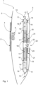
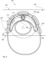
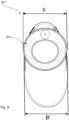
- the pouch of the ostomy appliance has a front wall and a rear wall.
- the filter construction has a first and second foil providing an enclosure for the elements in the filter construction.
- the filter construction may be attached inside the pouch bag so that, in use, the filter construction is substantially free-hanging in the pouch, meaning that the filter construction is able to follow the movements of the pouch and further is able to crumble and curl during use.
- Holes are provided at least in one of the first or second foils so as to provide for gas-inlets to the filter construction.
- Such an ostomy appliance will in use be able to evacuate excess gas through the filter at any time because the provision of the free-hanging filter construction ensures that at least one inlet is always open.
- the invention relates to an ostomy appliance as defined in claim 1.
- An ostomy appliance with a filter construction as described above will have excellent properties for preventing or at least reducing ballooning because the filter construction is free-hanging in the pouch.
- free-hanging is meant that the filter construction is able to follow the movements of the pouch substantially unhindered.
- the filter construction may be attached only in the area immediately surrounding the vent opening leaving most (if not all) of the contour of the enclosure unattached to the ostomy appliance.
- the filter construction is attached in discrete points across the surface of the second foil. This means that in one embodiment, a major part of the filter construction is able to crumble and curl during use, thus keeping the filter construction from clinging to the walls of the pouch, and thus keeping at least some of the gas-inlet(s) open at all times.
- crumbling and curling is meant that the filter construction obtains a wavy shape in the plane of the pouch.
- the free-hanging of the filter is so that the filter construction is cantilevered attached in the pouch.
- the surface area of the part of the filter construction that is attached is significantly smaller than remaining surface area of the filter construction.
- the attached area may constitute less than 20 % of the surface area of the filter construction, such as 10 % or 5 % or even as little as 1 %.
- An ostomy appliance is well-known in the art. It usually comprises a pouch having a front wall and a rear wall of gas- and liquid impermeable foil-material (for example of polyethylene (PE), polyvinyl-chloride (PVC) or ethylene-vinyl-acetate (EVA)) that is welded or glued around the edges or the rim so as to form a pouch defining a waste collection chamber.
- the pouch may be welded or glued only partly around the rim so that an opening for emptying the pouch is provided at the bottom of the pouch. In that case, the pouch may be provided with means for closing that opening.
- the pouch usually includes a waste inlet opening which at the outer side is provided either with mechanical or adhesive coupling means for coupling to a body side wafer or with a skin-friendly adhesive adapted for direct adhering to the abdomen of the user.
- the waste inlet opening is placed in the upper part of the ostomy pouch so that when a user stands up, the waste inlet opening will be above the midline of the ostomy pouch. This leaves a larger collecting volume below the waste inlet opening.
- the top of the ostomy appliance and the pouch is defined as the part closest to the waste inlet opening, and the bottom is defined as the opposite part.
- the longitudinal direction of the ostomy appliance and the pouch is defined as the direction from top to bottom.
- the transverse direction of the ostomy appliance, the pouch and filter construction positioned in the pouch is defined as the direction in the plane of the pouch perpendicular to the longitudinal direction.
- the axial direction is defined as the direction of the stoma.
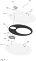
- the filter construction comprises a first and second layer of foil defining an enclosure for the filter construction.
- the first and second foil layers may be laminated to the surface of the elements (e.g. the pre-filter) in the filter construction.
- laminated is meant that the foils are attached to the entire surface, so that there is no space between the elements and the foil layers.
- the foils may be attached by means of gluing or heat welding.
- the foil layers are not necessarily attached to each other along their contour as well. If the foil layers are un-attached at their contour, or at least partly unattached along their contour, the unattached parts also define gas-inlets to the filter construction.
- the first and second foil layers may be attached to one another along their entire contour so as to define an enclosure.
- the pre-filter element may, during manufacturing, be compressed slightly in the cross-sectional direction of the filter construction. Compression of the pre-filter element ensures that there is no distance between the foils and the pre-filter element, thereby alleviating the risk of the liquid or semi-solid parts of output bypassing the pre-filter element. Thereby it is assured that the liquid material entering into the filter construction will flow through the pre-filter element.
- the foil layers may be attached to each other by means of welding, which is a fast process to use in manufacturing.
- the foil in itself may thus be weldable.
- the foils may also be attached to each other by a gluing process, e.g. using acrylate and/or hot melt adhesive.
- the foil may be gas- and liquid-impermeable.
- a material such as PE-foil would be suitable for use.
- the foil may be non-woven or textile. However it has to be ensured that the liquid or semi-solid part of the output travels at least some distance through the pre-filter element before reaching the deodorising element. Therefore the foils immediately surrounding the deodorising element must be gas- and liquid-impermeable.
- the gas- and liquid-impermeable foils may be provided in a distance of at least 3 cm from the deodorising element. In another embodiment, the gas- and liquid-impermeable foils may be provided in a distance of only 15 mm from the deodorising element. It depends on the type of output in the pouch, as described below.
- the filter construction includes a deodorising filter within the enclosure.
- the deodorising filter may be positioned on the outside surface of the pouch so that it communicates with the vent opening in the pouch.
- the deodorising filter may also be positioned inside the pouch communicating with the vent opening but outside the enclosure and communicating with the gas-outlet.
- the deodorising filter may be provided as filter packages typically used for ostomy bags.
- the deodorising filter will have a foil layer laminated to the surfaces of the deodorising filter that is parallel to the gas-flow direction. This assures that gas is forced to flow in the intended gas-flow direction of the deodorising filter. Thus an adequate deodorising is achieved.
- the filter construction may include more than one deodorising filter, such as two or three.
- the number of vent openings in the pouch should correspond to the number of deodorising filters in the filter construction.
- a filter package having a shape and flow-path as Filtrodor ® from Coloplast A/S may be used. This filter package comprises a disc-shaped foam element where the foam is impregnated in carbon.
- the foam element is covered with a gas-impermeable foil on both sides of the disc, except for a hole punched centrally in one of the foils.
- This hole functions as a gas-outlet to the deodorising filter and the periphery of the element functions as a gas-inlet.
- the gas-flow direction through the deodorising filter may also be opposite so that gas enters the deodorising filter centrally and exits at the periphery. When the gas has travelled the distance from the periphery of the disc to the centre (or vice-versa), it is adequately deodorised.
- the diameter of such an element may be approximately 20 to 25 mm but may be larger or smaller depending on the deodorising capacity.
- the deodorising filter may also be of elongated shape with an inlet in one end and an outlet in the other.
- Such a deodorising filter may be of the type described in European Patent no. EP0235928B1 .
- the deodorising filter could be a carbon loaded porous material such as foam, felt, nonwoven or the like, or the activated carbon could be based on a carbonized material such as e.g. carbonized viscose or the like.
- the carbon could either be nonactivated or activated by applying catalyzing compounds such as copper oxide, chromium oxide, potassium permanganate or other catalyzing compounds.
- At least one of the first and/or second foil layers is provided with holes of a diameter of approximately 0.1-2.0 mm. Both foil layers may also be provided with holes. These holes function as gas-inlets for letting gas enter into the filter construction. The small size of the holes helps prevent semi-solid and to a certain degree liquid material from entering into the filter construction but allows gas to enter.
- the position of the output depends on the user's movement (lying down or sitting up) and on the type of output.
- the output will typically at least sit near the rear wall of the ostomy bag. In this case, the holes in the foil facing the front wall will be accessible for gas.
- the output may also sit near the front wall and in this case, the holes in the foil facing the rear wall will be accessible for gas.
- the holes may be made by punching, burning, and etching or by use of a laser, drill, needle or dinking die.
- the number of holes may be anything between 1 hole for an ileostomy bag up to more than 150 holes for a colostomy bag. The number of holes depends on the size of the filter construction and the type of output exiting the stoma.
- the filter construction of this invention is contemplated to be used in connection with an ileostomy as well as a colostomy.
- the two types of stomas typically deliver different types of output.
- the output is typically thinner and more syrupy whereas the output from a colostomy is typically more like porridge.
- the type of output may also depend on the intake of food and liquids - therefore, we will in the following refer to thin output (syrupy to liquid) and thicker output (like porridge) irrespective of whether it comes from an ileostomy or a colostomy.
- the reference is to a largest diameter of the hole in case the hole is not circular but rather elliptical. If the hole is more angular, then the reference is, again, to a largest "diameter" which in this case may be the longest diagonal dimension across the hole.
- a first distance between two neighbouring holes is so that liquid cannot travel from one hole to the neighbouring hole within the normal use time.
- a second distance from the deodorising element to the nearest gas-inlet is so that liquid cannot travel from the nearest gas-inlet to the deodorising element within the normal use time.
- first distance between the holes or a second distance between the gas-inlets and the deodorising element are in the planar direction of the filter construction.
- second distance is defined as the distance in a direction in the plane of the foils of the filter construction from the gas-inlet closest to the deodorising filter to the edge of the deodorising filter closest to the same gas-inlet.
- planar direction is defined by the foil layers of the filter construction so that each foil extends in the planar direction.
- the clogging of the filter construction occurs when all gas-inlets are blocked by output.
- the gas-inlets may be blocked by semi-solid material smeared across the hole thereby closing the hole.
- the first distance between neighbouring holes and the second distance from the gas-inlets to the deodorising element ensures that output clogging one hole will not be able to travel through the pre-filter material along the surface of the foil and into the next hole or into the deodorising element and clogging that as well. Liquid and semi-solid matter entering into the deodorising element may leave this element bereft of its ability to deodorise the flatus gas.
- the second distance is in an embodiment at least 5 mm. Only a small amount of liquid will be able to enter into the pre-filter element because of the small holes in the foils of the filter construction, thus only a short distance is needed to be able to stop this liquid. However, the second distance may also be approximately 3 cm. Again there is a difference between thin and thick output. Thick output will not be able to travel very far into the pre-filter element, therefore the second distance between the gas-inlets and the deodorising filter may be rather low, for example as low as 5 mm. In an embodiment, the smallest distance between the deodorising element and a gas-inlet is more than 15 mm. Thereby it is ensured that no liquid or semisolid matter will reach the deodorising element during the normal use time.
- the second distance between the gas-inlets and the deodorising filter should be longer, for example at least 3 cm.
- a third distance between gas-inlets and the rim of the filter construction may be more than 5 mm. When the gas-inlets are near the rim of the filter construction, there is no neighbouring hole in the direction of the rim. Therefore, the distance may be smaller here.
- the foil enclosure defining the filter construction may be provided with a drainage opening facing downwards in the ostomy bag - that is facing towards the bottom of the ostomy bag. This bottom facing drainage opening provides an opportunity for particularly thin output to be drained out of the filter construction.
- the opening may be provided with a one-way valve so that output in the bag is prevented from entering into the filter construction through this opening.
- a one-way valve is well-known in the art and may for example be provided as a foil valve.
- the filter construction further includes a flange surrounding the gas-outlet.
- the filter flange may be an injection moulded flange.
- This filter flange serves the purpose of providing an element for welding the filter construction to the ostomy bag.
- the positioning of the filter construction is independent of the production of the ostomy bag and can be done either during production of the ostomy bag or at any time afterwards.
- the filter flange is made of a material that is substantially nonconductible and able to absorb heat. Therefore the heat from the welding process is not transferred to the filter construction.
- the filter construction can be manufactured as a finished element, including the pre-filter element and the deodorizing filter, and subsequently welded to the bag without risking that the foils and pre-filter element are welded to each other.
- the filter flange may be made of a material such as PE or EVA which materials both are able to quickly weld to the ostomy bag.
- the welding can be done at for example 160°C for approximately 1 ⁇ 2 second.
- the thickness of the flange should be above approximately 0.5 mm to be able to absorb the heat from welding so as to prevent the foils and the pre-filter element from welding to each other. The upper limit for the thickness is controlled by the requirement for a discreet bag - therefore it should be below approximately 1 mm.
- the filter flange may be glued to the bag instead of welded to it. This may be done using an acrylate or hot melt adhesive.
- the filter construction may also be directly welded to the ostomy bag, meaning that the filter flange may be omitted.
- the deodorising filter is directly welded to the bag, that is, the foil that covers the deodorising filter is welded to the front or rear wall of the ostomy bag.
- the foils covering the deodorising filter may in an embodiment of the invention be made of a three-layer foil structure laminated to the deodorising filter.
- the foils may be made of gas impermeable and liquid impermeable barrier foils, so that gas and liquid are prevented from exiting the filter at any other position than the defined gas-outlet.
- the three-layer structure may be made of an outer foil layer, which is adapted to be welded to the bag foil, an intermediate foil layer adapted to function as an intermediate protective layer and an inner foil layer adapted to be laminated to the deodorising filter.
- the intermediate layer protects the foil structure from pin-holes occurring through the layers.
- the protective ability is provided by ensuring that the intermediate foil layer has a significantly higher melting temperature than the outer and inner foil layers.
- the outer and inner foil layers may have a melting temperature between 80°C and 150°C and the intermediate layer may in that situation have a melting temperature above 200°C.
- the outer and inner layer may be made of a copolymer of Ethylene-Vinyl-Acetate (EVA) and Poly-Ethylene (EVAPE) and the intermediate layer may be made of Poly-Amide (PA).
- a three-layer structure as described, may be welded or laminated to the side of the deodorising filter facing outwards when positioned in the ostomy bag.
- the avoidance of pin-holes and the gas impermeability is less important because gas leaking through the foils will only re-enter the ostomy bag.
- the three-layer foil structure may nevertheless be used on the inside as well, thereby avoiding the need for using separate foils. Anyhow, leakage of gas towards the outside is to be avoided.
- this filter may in itself serve as a heat-absorbable flange, because the deodorising filter is able to absorb the heat from the welding process.
- the pre-filter element may be made of foam material, for example of PE or poly-urethane (PU).
- the pore size may be between 15 and 100 PPI, such as 30 or 45 PPI.
- PPI is a unit giving a measure for the pore size although it actually refers to the number of pores per inch in the foam material.
- Felt, fluff, nonwoven or any other porous material may also be used.
- Gas including solid and/or semi-solid waste material) will enter into the pre-filter element through the holes in the foil layers that provides the gas-inlets to the filter construction. Due to the tortuous structure of the foam, most of the liquid and semi-solid waste will be captured in the foam leaving only gas to pass through the foam to reach the deodorising filter.
- the thickness of the pre-filter element may be between 1 and 5 mm such as approximately 2 or 3 mm.
- the thickness is defined as the dimension in the direction across the filter construction corresponding to the dimension of the pre-filter element in the direction from the first foil layer towards the second foil layer.
- the area of the pre-filter element may be so large that it has almost the same area as the front or rear wall of the pouch. However, room should be left for manufacturing tolerances.
- the area of the pre-filter element may be as low as 10 % of the area of the front or rear wall when taken in the plane of the pouch. This will be the case if a large pouch is used, for example a Maxi-pouch.
- the area of the pre-filter element may be up to 80 or 90 % of the area of the front or rear wall of the pouch. This may particularly be true for small pouches, for example a Mini-pouch.
- a large pre-filter element may be advantageous for bags filled with thin output, because it is difficult to completely prevent thin output from entering into the pre-filter element. Thus a large volume of foam is needed to prevent the thin output from reaching the deodorising filter.
- a large pre-filter element may also be advantageous for bags filled with thicker output, because a large number of gas-inlets are needed to ensure that at least some gas-inlets are open. As mentioned earlier, when thick output is present in the bag, the gas-inlets will be blocked because of the smearing of the output over the inlet holes. Thus a large area of foil provided with gas-inlets is needed, when the bag is filled with thick output.
- the gas-outlet of the filter construction communicates with the vent opening in form of a hole or slit in the ostomy bag so that gas exiting the gas-outlet enters through the vent opening and out in the ambience or through the deodorising filter if this is positioned on the outside of the pouch.
- the communication may be done by positioning the gas-outlet in alignment with the vent opening or at least in the near vicinity of the vent opening.
- the vent opening should be enclosed, for example by a weld surrounding the vent opening, so that gas from the pouch is prevented from exiting the vent opening without having passed through the filter construction. Typically, this can be ensured by welding the filter construction to the ostomy pouch in an uninterrupted weld, so that the gas-outlet and the vent opening lie within the boundaries of the weld.
- the filter construction further includes a membrane positioned at the gas outlet.
- This membrane is gas-permeable, but moisture-impermeable.
- the membrane may be microporous and hydrophobic and made of a material like Goretex ® or Tyvek ® .
- the membrane should be able to provide a flow through of between 100 to 550 ml/min at 0.01 bar pressure difference, for example 250 ml/min or 350 ml /min.
- the membrane may be attached, e.g. adhered, to the surface of the deodorising filter, i.e. between the surface of the deodorising filter and the "inner" surface of the second foil.
- the membrane is positioned on the outside of the second foil - that is between the gas-outlet and the vent opening on the pouch.
- the foil layers of the filter construction may enclose the pre-filter element, the deodorising filter and the membrane.
- the pre-filter element comprises a cut-out for the deodorising filter.
- the cut-out may be disc-shaped to match a disc-shaped deodorising filter.
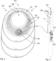
- the gas inlets are placed near the periphery of the filter construction and the deodorising filter has its gas-inlet along the periphery of it and a substantially centrally placed outlet.
- the pre-filter element may be provided as an annular foam-element. It may have a circular or angular outer periphery. A part (for example the central part) of the pre-filter element is removed by punching or cutting a cut-out in the pre-filter element thereby leaving room for the deodorising filter.
- the cut-out for the deodorising filter substantially matches the outer contour of the deodorising filter. If the deodorising filter is disc-shaped, then the cut-out for the deodorising filter is generally disc-shaped and if the deodorising filter is angular or banana-shaped, the cut-out for the deodorising filter will be provided with generally that shape. Matching the cut-out for the deodorising filter with the deodorising filter provides a more compact structure.
- Gas entering into the filter construction through the gas-inlets at the periphery will travel through the pre-filter element towards the inner periphery of the pre-filter element and from there into the deodorising filter. Then the gas will travel transversely through the deodorising filter and exit the filter construction at the opening in one of the foil layers providing the gas-outlet.
- the pre-filter element is positioned next to the deodorising filter so that they are positioned juxtaposed each other within the filter construction.
- the deodorising filter will be positioned at one end of the filter construction.
- the pre-filter and the deodorising element may, in other words, be positioned sequentially.
- the filter construction may thus be elongated and preferably slightly curved so that it can follow the contour of the ostomy bag.
- the pre-filter element and the deodorising filter are positioned in the same plane.
- the deodorising filter is positioned atop the pre-filter element.
- the invention relates to the filter construction incorporating an inspection window allowing the user visual access to the stoma and possibly also the peristomal area.
- This inspection window may be provided in the pre-filter element so that the pre-filter element is a generally disc-shaped element having a circular hole with a diameter of at least the diameter of the waste inlet opening, where the foil layers of the filter construction are welded along the periphery of the circular hole in the pre-filter element.
- either the foil layers need to be transparent or they need to be removed in the circular hole.
- the inspection window is placed off-centre in the pre-filter element and the deodorising filter is placed in a cut-out for the deodorising filter.
- the inspection window may be placed so that it leaves a thin strip of pre-filter element above the waste inlet opening and a larger area with the cut-out for the deodorising filter below the waste inlet opening. Thereby, the deodorising filter will be placed below the waste inlet opening.
- the inspection window may also be placed so that a thin strip of the pre-filter element is below the waste inlet opening and the larger area including the cut-out for the deodorising filter and the deodorising filter is placed above the waste inlet opening.
- the stoma-inspection window allows a user to inspect the stoma and the peristomal area from the outside of the ostomy appliance. This requires that part of the front wall of the pouch is transparent.
- the diameters of the individual parts may in a specific embodiment be as follows: the deodorising filter, 30 mm, the pre-filter element, 110 mm and the inspection window in the pre-filter element, 70 mm.
- the inspection window may be provided because the pre-filter element is banana-shaped and positioned above the stoma and thus not in the way of viewing the stoma.
- the pre-filter element may be placed above and partly around the waste-inlet opening. This pre-filter element may have a circular hole in the middle of the banana-shape to provide room for the deodorising filter.
- An embodiment of the invention relates to providing a filter flap as described in European Patent EP1578308B1 in an ostomy appliance according to this invention.
- an ostomy appliance comprising
- An ostomy appliance with a filter construction will be able to evacuate the gas from the bag at all times.
- the provision of the gas-inlets in one of the foil layers or in both layers provide for pathways through the pre-filter at all times.
- the position of the foils parallel to the front and rear wall helps minimise the risk of covering the gas-inlets with output during use.
- an ostomy appliance in an embodiment includes a deodorising filter positioned inside the enclosure so that gas exiting the pre-filter element enters directly into the deodorising filter and from there out through the gas-outlet.
- a gas flow direction is defined as the direction in which the gas flows from the gas-inlets through the pre-filter element, through the deodorising filter and out through the gas-outlet and vent opening.
- the filter construction may comprise one or more carrying means attached to the bag foils at the time of the contour welding process step.
- the carrying means may be separate or integral parts of one or both of the foil layers of the filter construction; if separate they may be attached to the foil layer(s) by welding or gluing.
- the carrying means may attach the filter construction to the contour of the ostomy bag in the upper part thereof so that during use, gravity aids in forcing the filter construction downwards into the bag and keeping it in a desired position.
- the carrying means may also attach the filter construction in a lower position, if this is desired.
- the filter construction will thus be prevented from being torn off inside the bag during use. To a certain extent, the filter construction will still be able to crumble during use. This is because the carrying means only attach the upper part of the filter construction to the ostomy bag. Thus, the lower part of the filter construction may still be free-hanging.
- an ostomy appliance comprising
- An ostomy appliance with a filter construction will be able to evacuate the gas in the pouch at all times.
- the positioning of the gas-inlets at the foil layer(s) of the filter construction and the ability of the filter construction to crumble ensures that at least one inlet is open at all times particularly when the pouch is filled or ballooning occurs in the pouch.
- the bag When the pouch fills up, the bag will change shape towards a more blown up, longitudinal configuration. This means that the lower part of the pouch may move slightly downwards due to the load in the pouch and at the same time or alternatively, the pouch may be thicker in the axial direction (outwards in direction of the stoma). This leads to a decrease in the width direction and will lead to crumbling of the filter construction.
- the filter construction may obtain a crumbling when the pouch is filled as a result of the relationship between the width of the filter construction and the width of the pouch in the transverse direction.
- the pouch may assume any configuration between the first and second configuration.
- the width of the pouch is substantially unaltered when compared to the original width of a new, un-used pouch.
- the width of the pouch is reduced compared to the original width of a new, un-used pouch.
- the filter construction has a width in the transverse direction which is at least 100 %, such as at least 80 % or at least 60 % of the width of the pouch in the transverse direction.
- the width of the filter construction is meant to be the largest width across the filter construction in the transverse direction in the plane of the foil layers.
- the width of the pouch is the largest width across the bag in the transverse direction, in the plane of the walls of the pouch.
- the filter construction When the filter construction has a width corresponding to the pouch - and the filter construction is entered into the pouch - then the filter construction will obtain a wavy shape or curl slightly as soon as it is entered into the pouch. This will assist in providing access to the gas-inlet(s) positioned across the surface of the filter construction.
- the width of the pouch is reduced.
- a filter construction that can be easily mounted inside the pouch is obtained, because the difference in width leaves room for attaching the filter construction to either the front or rear wall of the pouch and then subsequently attaching the front or rear wall to each other along their rim by any known means.
- the 80 % provides for the manufacturing tolerances of the filter construction and the pouch, while still providing a filter that is able to curl when the pouch is filled or balloons, because the width of the pouch is reduced to below 80 % of the original width of a new, un-used pouch.
- Such an ostomy appliance is particularly useful for use with an ileostomy, because it has few, large holes and a large area of pre-filter element. Thus it utilises the fact that it is not possible to prevent thin output from entering into the pre-filter, but the pre-filter element is large enough to be able to contain it through-out the normal wear-time for ileostomy bags. The large holes make it (almost) impossible for the thin output from an ileostomy to clog the holes by smearing output over them.
- Such an ostomy appliance is particularly useful for use with a colostomy because most of the output coming out of a colostomy is rather thick and thus, as described above, the filter construction will be clogged because the output gets smeared across the surface of the filter construction - therefore, the number of holes needs to be large and positioned in both foils so as to prevent all of them from being clogged. Furthermore, output coming out of a colostomy may comprise thinner output as well - therefore it is advantageous if the diameter of the gas-inlets varies.
- an ostomy appliance comprising a pouch and a filter construction comprising a first foil layer and a second foil layer defining an enclosure, the enclosure including a pre-filter element, wherein multiple gas-inlets are provided in at least one of the foil layers, a gas-outlet being provided in the second foil layer, the filter construction being attached inside the pouch so that a major part of the filter construction is left free-hanging in the pouch, the method comprising placing the appliance around the stoma.
- the pouch is provided with a vent opening and the filter construction is positioned so that the gas-outlet of the filter construction communicates with the vent opening of the pouch.
- an ostomy appliance comprising a pouch and a filter construction, comprising a first foil layer and a second foil layer defining an enclosure, the enclosure including a pre-filter element, wherein multiple gas-inlets are provided in at least one of the foil layers, a gas-outlet being provided in the second foil layer, the filter construction being attached inside the pouch so that a major part of the filter construction is left free-hanging in the pouch, for use in a method of collecting ostomy discharge, the method comprising placing the appliance around the stoma.
- the pouch may be provided with a vent opening and the filter construction is positioned so that the gas-outlet of the filter construction communicates with the vent opening of the pouch.
- the ostomy discharge may be collected during the night.
- a method and an ostomy appliance as described allows a user to sleep through most of the night because they will not be disturbed by ballooning of their ostomy bag.
- an ostomy appliance comprising a pouch and a filter construction comprising a first foil layer and a second foil layer defining an enclosure, the enclosure including a pre-filter element, wherein multiple gas-inlets are provided in at least one of the foil layers, a gas-outlet being provided in the second foil layer, the filter construction being attached inside the pouch so that a major part of the filter construction is left free-hanging in the pouch, the method comprising placing the ostomy appliance around a stoma.
- an ostomy appliance comprising a pouch and a filter construction comprising a first foil layer and a second foil layer defining an enclosure, the enclosure including a pre-filter element, wherein multiple gas-inlets are provided in at least one of the foil layers, a gas-outlet being provided in the second foil layer, the filter construction being attached inside the pouch so that a major part of the filter construction is left free-hanging in the pouch, for use in a method of reducing the number of ballooning(s) occurring in an ostomy appliance, the method comprising placing the ostomy appliance around a stoma.
- ostomy appliances according to this invention are able to reduce the number of balloonings occurring by more than 50 % - se the paragraph below. This means that a user will be less bothered by balloonings when wearing an ostomy appliance according to this invention, thus leading to fewer embarrassing situations occurring and fewer detachments of the pouch from the wafer or of the appliance from the skin of the user.
- an ostomy appliance comprising a pouch and a filter construction comprising a first foil layer and a second foil layer defining an enclosure, the enclosure including a pre-filter element, wherein multiple gas-inlets are provided in at least one of the foil layers, a gas-outlet being provided in the second foil layer, the filter construction being attached inside the pouch so that a major part of the filter construction is left free-hanging in the pouch, the method comprising placing the ostomy appliance around a stoma.
- an ostomy appliance comprising a pouch and a filter construction comprising a first foil layer and a second foil layer defining an enclosure, the enclosure including a pre-filter element, wherein multiple gas-inlets are provided in at least one of the foil layers, a gas-outlet being provided in the second foil layer, the filter construction being attached inside the pouch so that a major part of the filter construction is left free-hanging in the pouch, for use in a method of increasing the time before ballooning occurs in an ostomy appliance, the method comprising placing the ostomy appliance around a stoma.
- ostomy appliances according to this invention are able to increase the time before a ballooning occurs with more than 70 % - see the paragraph below. This means that a user will be able to wear an ostomy appliance according to the invention for a longer time before having problems with ballooning. This may lead to a better and more un-interrupted sleep at night, because the user does not have to get up to let air out of the ostomy appliance.
- the ostomy appliance may be placed around a colostomy and the first and second foil layers are provided with gas-inlets in a number exceeding 50.
- the number of gas-inlets for use with a colostomy may also be more than 75, such as more than 100 and even more than 150 holes.
- the ostomy appliance may be placed around an ileostomy and at least one of the foil layers is provided with at least one gas-inlet of a diameter of at least 1 mm and the pre-filter element has a volume large enough to handle the liquid output entering into the pre-filter element through-out the normal wear time.
- the number of gas-inlets may in this embodiment be 2 holes.
- a volume large enough to handle the liquid output means that the thickness of the pre-filter (in the axial direction of the stoma) is at least 5 mm and the area of the pre-filter in the plane of the filter construction is at least 40 % of the area of the rear wall.
- Ostomy appliances as described above have been tested by users having a colostomy (20 users) and users having an ileostomy (20 users). The tests have been compared to reference ostomy appliances comprising two filter constructions each with a pre-filter of porous material 50 mm x10 mm x 3 mm and a deodorising filter of carbonised foam 30 mm x 7 mm x 3 mm.
- the study was designed as an open, randomised cross-over study. All users were using one-piece ostomy appliances and should usually experience ballooning problems at least once a week. The users were instructed to change the ostomy appliance when they experienced ballooning and should otherwise follow the normal changing pattern.
- the number of reference ostomy appliances tested was 567 appliances and the number of ostomy appliances according to this invention was 526 appliances.
- the number of balloonings in the reference appliances was 129 and the number of balloonings in the appliances according to this invention was 59.
- the number of balloonings experienced by the appliances of this invention was decreased by 52 %.
- the number of reference ostomy appliances tested was 294 appliances and the number of ostomy appliances according to this invention was 283 appliances.
- the number of balloonings in the reference appliances was 161 and the number of balloonings in the appliances according to this invention was 74.
- the number of balloonings experienced by the appliances of this invention was decreased by 62 %.
- Colostomy users testing the reference appliances experienced in average ballooning approximately every 1.5 day (0.72 balloonings/per user/per day).
- the same users tested the ostomy appliances according to this invention they experienced in average ballooning approximately every 4 th day (0.26 balloonings/per user/per day).
- the time before ballooning occurs increased by 74 %.
- Ileostomy users testing the reference appliances experienced in average ballooning almost every day (0.90 balloonings/per user/per day).
- the same users tested the ostomy appliances according to this invention they experienced in average ballooning approximately every 3 rd day (0.34 balloonings/per user/per day).
- the time before ballooning occurs increased by 82 %.
- the apparatus includes a differential pressure meter to monitor the pressure and a flow controller to monitor the airflow. Additionally, the apparatus can apply a controlled simulation of a contamination event for an ostomy bag filter.
- the filter tester apparatus applies a controlled massaging and shaking of an ostomy bag containing a simulated colo- or ileo-output.
- the simulated colo-output has a consistency like porridge and the simulated ileo-output has a consistency like syrup.
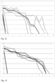
- the testing was carried out by mounting an ostomy bag containing simulated Colo-output medium in the filter tester apparatus. Following this, the ostomy bag was inflated to 10 mbar. When the pressure was stable at 10 mbar, the flow through the uncontaminated filter construction was determined by reading the value at the flow controller.
- the ostomy bag was deflated and the first contamination cycle was performed by allowing the massage plate to move forward to the ostomy bag and massage the output containing ostomy bag, resulting in a controlled contamination of the surfaces within the ostomy bag, including the filter construction.
- the ostomy bag was again inflated to 10 mbar and the flow through the filter construction was determined as described above.
- This contamination step was repeated until the filter construction was clogged.
- the flow through the filter construction was determined at 10 mbar for each contamination cycle.
- ostomy bags with a filter construction according to this invention was tested and compared to ostomy bags with a reference filter construction.
- the filter construction according to this invention included a pre-filter element having a generally circular periphery of about 110 mm and having an inspection hole of about 60 mm cut off centre.
- the filter construction is further provided with a hole for a deodorising element of about 30 mm positioned in the lower part of the pre-filter element.
- the reference filter construction comprises a pre-filter of porous material 50 mm x10 mm x 3 mm and a deodorising filter of carbonised foam 30 mm x 7 mm x 3 mm.
- the ostomy bags according to this invention were of two different kinds.
- the ostomy bags were bags adapted to be used with a colostomy and were thus provided with 96 holes functioning as gas-inlets. The holes were punched with a needle with a diameter below 1 mm; approximately 0.5 mm. 6 holes of approximately 1 mm in diameter were included.
- four ostomy bags according to this invention and five reference bags were tested. All bags (the sample bags and the reference bags) were filled with a test-medium which is comparable to porridge like the output mentioned earlier. The table below shows how many contamination cycles each bag were subjected to before there was no flow through the bag.
- the ostomy bags according to this invention (sample 1 to sample 4) and filled with colo-like output to a great extent out-perform the reference bags (ref. 1 to ref. 5).
- the ostomy bags according to this invention lasted 13 contamination cycles compared to only 1-2 cycles for the reference bags.
- Series 1.2 comprises ostomy bags according to the invention and adapted to be used with an ileostomy. These bags were thus provided with 2 holes of approximately 1 mm in diameter functioning as gas-inlets.
- four ostomy bags according to this invention and five reference bags were tested. All bags (the sample bags and the reference bags) were filled with a test-medium which is comparable to syrupy output mentioned earlier.
- the table below shows how many contamination cycles each bag were subjected to before there was no flow through the bag.
- Table 2 Ostomy bag ileo-sample 1 ileo-sample 2 ileo-sample 3 ileo-sample 4 contamination cycles 12 13 11 12 ostomy bag ref. 1 ref. 2 ref. 3 ref. 4 ref. 5 contamination cycles 1 1 1 1 1 1 1
- the ostomy bags according to this invention (sample 1 to sample 4) and filled with ileo-like output to a great extent out-perform the reference bag (ref. 1 to ref. 5).
- the ostomy bags according to this invention lasted 12 contamination cycles compared to only 1 cycle for the reference bag.
Landscapes
- Health & Medical Sciences (AREA)
- Epidemiology (AREA)
- Nursing (AREA)
- Orthopedic Medicine & Surgery (AREA)
- Engineering & Computer Science (AREA)
- Biomedical Technology (AREA)
- Heart & Thoracic Surgery (AREA)
- Vascular Medicine (AREA)
- Life Sciences & Earth Sciences (AREA)
- Animal Behavior & Ethology (AREA)
- General Health & Medical Sciences (AREA)
- Public Health (AREA)
- Veterinary Medicine (AREA)
- Orthopedics, Nursing, And Contraception (AREA)
Applications Claiming Priority (10)
| Application Number | Priority Date | Filing Date | Title |
|---|---|---|---|
| DKPA201070246 | 2010-06-04 | ||
| DKPA201070245 | 2010-06-04 | ||
| DKPA201070476 | 2010-11-08 | ||
| DKPA201070473 | 2010-11-08 | ||
| DKPA201070475 | 2010-11-08 | ||
| DKPA201070498 | 2010-11-19 | ||
| EP16188304.6A EP3141224B1 (en) | 2010-06-04 | 2011-06-01 | Ostomy bag with filter construction |
| EP18168449.9A EP3400915B1 (en) | 2010-06-04 | 2011-06-01 | An ostomy appliance with a filter construction |
| EP11726057.0A EP2575704B1 (en) | 2010-06-04 | 2011-06-01 | An ostomy bag with a filter construction |
| PCT/DK2011/050189 WO2011150936A1 (en) | 2010-06-04 | 2011-06-01 | An ostomy bag with a filter construction |
Related Parent Applications (3)
| Application Number | Title | Priority Date | Filing Date |
|---|---|---|---|
| EP11726057.0A Division EP2575704B1 (en) | 2010-06-04 | 2011-06-01 | An ostomy bag with a filter construction |
| EP16188304.6A Division EP3141224B1 (en) | 2010-06-04 | 2011-06-01 | Ostomy bag with filter construction |
| EP18168449.9A Division EP3400915B1 (en) | 2010-06-04 | 2011-06-01 | An ostomy appliance with a filter construction |
Publications (2)
| Publication Number | Publication Date |
|---|---|
| EP3733137A1 EP3733137A1 (en) | 2020-11-04 |
| EP3733137B1 true EP3733137B1 (en) | 2024-10-23 |
Family
ID=59078877
Family Applications (5)
| Application Number | Title | Priority Date | Filing Date |
|---|---|---|---|
| EP19209910.9A Active EP3733137B1 (en) | 2010-06-04 | 2011-06-01 | An ostomy appliance with a filter construction |
| EP18168449.9A Active EP3400915B1 (en) | 2010-06-04 | 2011-06-01 | An ostomy appliance with a filter construction |
| EP11726057.0A Active EP2575704B1 (en) | 2010-06-04 | 2011-06-01 | An ostomy bag with a filter construction |
| EP16188304.6A Active EP3141224B1 (en) | 2010-06-04 | 2011-06-01 | Ostomy bag with filter construction |
| EP14163858.5A Active EP2754426B1 (en) | 2010-06-04 | 2011-06-01 | An ostomy appliance with a filter construction |
Family Applications After (4)
| Application Number | Title | Priority Date | Filing Date |
|---|---|---|---|
| EP18168449.9A Active EP3400915B1 (en) | 2010-06-04 | 2011-06-01 | An ostomy appliance with a filter construction |
| EP11726057.0A Active EP2575704B1 (en) | 2010-06-04 | 2011-06-01 | An ostomy bag with a filter construction |
| EP16188304.6A Active EP3141224B1 (en) | 2010-06-04 | 2011-06-01 | Ostomy bag with filter construction |
| EP14163858.5A Active EP2754426B1 (en) | 2010-06-04 | 2011-06-01 | An ostomy appliance with a filter construction |
Country Status (13)
Families Citing this family (90)
| Publication number | Priority date | Publication date | Assignee | Title |
|---|---|---|---|---|
| WO2008134334A1 (en) | 2007-04-24 | 2008-11-06 | Bristol-Myers Squibb Company | Closure system for a drainable pouch |
| JP5474779B2 (ja) | 2007-06-12 | 2014-04-16 | コンバテック・テクノロジーズ・インコーポレイテッド | オストミー用装置 |
| US10646370B2 (en) | 2008-04-01 | 2020-05-12 | Donaldson Company, Inc. | Enclosure ventilation filter and assembly method |
| CA2740318C (en) | 2008-11-19 | 2017-02-14 | Convatec Technologies Inc. | Ostomy pouch appliance |
| CA2766116C (en) | 2009-07-07 | 2017-12-05 | Convatec Technologies Inc. | Pressure sensitive silicone adhesives with amphiphilic copolymers |
| US9314365B2 (en) | 2009-07-14 | 2016-04-19 | B. Braun Medical Sas | Ostomy port gas release mechanism |
| JP5738866B2 (ja) | 2009-09-11 | 2015-06-24 | コンバテック・テクノロジーズ・インコーポレイテッドConvatec Technologies Inc | 排出制御造瘻術用器具およびそのためのシールド |
| DK3141224T3 (da) * | 2010-06-04 | 2019-08-26 | Coloplast As | Stomipose med filterkonstruktion |
| BR112012030175B1 (pt) * | 2010-06-04 | 2020-11-03 | Coloplast A/S | bolsa de ostomia |
| US10285847B2 (en) * | 2011-09-29 | 2019-05-14 | Convatec Technologies Inc. | Ostomy pouch with filtering system |
| PL2621418T3 (pl) * | 2010-09-30 | 2017-11-30 | Convatec Technologies Inc. | Woreczek stomijny z układem filtrującym |
| EP2637613B1 (en) * | 2010-11-08 | 2015-10-14 | Coloplast A/S | Ostomy bag with intermediate filter element |
| US9999536B2 (en) * | 2010-12-27 | 2018-06-19 | Benson Turtleneck Barrier Llc | Ostomy barrier seal |
| GB201115160D0 (en) | 2011-09-02 | 2011-10-19 | Trio Healthcare Ltd | Discharge solidifier and malodour control |
| JP2015515905A (ja) | 2012-05-10 | 2015-06-04 | スティマティックス ジーアイ リミテッド | 造瘻術器具 |
| EP2668935A1 (en) * | 2012-05-31 | 2013-12-04 | Hollister Incorporated | An ostomy pouch |
| GB2510398B (en) | 2013-02-01 | 2017-10-25 | Salts Healthcare Ltd | Ostomy appliance |
| GB2512655B (en) * | 2013-04-05 | 2017-10-25 | Salts Healthcare Ltd | Ostomy appliance |
| BR112015028181A2 (pt) * | 2013-05-09 | 2020-10-06 | Stimatix Gi Ltd | filtro e liberação de gás para aparelho de ostomia |
| US10531977B2 (en) | 2014-04-17 | 2020-01-14 | Coloplast A/S | Thermoresponsive skin barrier appliances |
| US10478329B2 (en) | 2014-04-24 | 2019-11-19 | Convatec Technologies Inc. | Ostomy pouch filter system |
| AU2016340143B2 (en) | 2015-10-14 | 2020-10-29 | Convatec Technologies Inc. | A medical device with an opening system |
| EP3451980B2 (en) * | 2016-05-04 | 2025-06-11 | Hollister Incorporated | Ostomy pouch with tortuous path |
| GB201609954D0 (en) * | 2016-06-07 | 2016-07-20 | Monty Stephanie | A dressing |
| TWI666008B (zh) * | 2017-07-17 | 2019-07-21 | 林志豪 | 造口接合儲存裝置 |
| CN107374808B (zh) * | 2017-08-29 | 2024-02-20 | 青岛大学附属医院 | 一种自动调节松紧度的造瘘碗 |
| GB2566721B (en) * | 2017-09-22 | 2020-07-15 | Salts Healthcare Ltd | An ostomy appliance |
| GB201715388D0 (en) * | 2017-09-22 | 2017-11-08 | Salts Healthcare Ltd | An ostomy appliance |
| CA3079131A1 (en) | 2017-11-09 | 2019-05-16 | 11 Health and Technologies Inc. | Ostomy monitoring system and method |
| EP4042985A1 (en) | 2017-12-22 | 2022-08-17 | Coloplast A/S | Processing schemes for an ostomy system, monitor device for an ostomy appliance and related methods |
| EP3727238B1 (en) * | 2017-12-22 | 2024-05-01 | Coloplast A/S | Sensor assembly part and a base plate for an ostomy appliance and a method for manufacturing a base plate or a sensor assembly part |
| WO2019120451A1 (en) * | 2017-12-22 | 2019-06-27 | Coloplast A/S | Base plate and a sensor assembly part for an ostomy appliance and a method for manufacturing a base plate and sensor assembly part |
| AU2018391391B2 (en) * | 2017-12-22 | 2024-03-21 | Coloplast A/S | Base plate for an ostomy appliance and a sensor assembly part for a base plate and a method for manufacturing a base plate and sensor assembly part |
| US11471318B2 (en) | 2017-12-22 | 2022-10-18 | Coloplast A/S | Data collection schemes for a medical appliance and related methods |
| WO2019120441A1 (en) | 2017-12-22 | 2019-06-27 | Coloplast A/S | Sensor assembly part and a base plate for an ostomy appliance and a method for manufacturing a sensor assembly part and a base plate |
| WO2019120427A1 (en) | 2017-12-22 | 2019-06-27 | Coloplast A/S | Sensor assembly part for an ostomy appliance and a method for manufacturing a sensor assembly part |
| WO2019120431A1 (en) | 2017-12-22 | 2019-06-27 | Coloplast A/S | Tools and methods for cutting holes in an ostomy appliance |
| US10849781B2 (en) * | 2017-12-22 | 2020-12-01 | Coloplast A/S | Base plate for an ostomy appliance |
| US11628084B2 (en) | 2017-12-22 | 2023-04-18 | Coloplast A/S | Sensor assembly part and a base plate for a medical appliance and a device for connecting to a base plate or a sensor assembly part |
| WO2019120425A1 (en) | 2017-12-22 | 2019-06-27 | Coloplast A/S | Ostomy appliance system, monitor device, and method of monitoring an ostomy appliance |
| EP3727247B1 (en) | 2017-12-22 | 2022-04-20 | Coloplast A/S | Tools and methods for placing an ostomy appliance on a user |
| JP7462558B2 (ja) * | 2017-12-22 | 2024-04-05 | コロプラスト アクティーゼルスカブ | 角度的漏出検出を用いるオストミーシステム及びモニタデバイス |
| EP3996106A1 (en) | 2017-12-22 | 2022-05-11 | Coloplast A/S | Monitor device of an ostomy system and associated method for operating a monitor device |
| EP3727240B2 (en) | 2017-12-22 | 2025-01-01 | Coloplast A/S | Accessory devices of an ostomy system, and related methods for communicating operating state |
| EP3727245B1 (en) | 2017-12-22 | 2025-04-30 | Coloplast A/S | SCHEMES FOR TRANSMITTING DATA FROM AN OSTOMY SYSTEM, MONITORING DEVICE FOR AN OSTOMY APPLIANCE, AND RELATED METHODS |
| CN111465372B (zh) | 2017-12-22 | 2022-09-06 | 科洛普拉斯特公司 | 用于造口术底板和传感器组件部的具有铰链的联接部 |
| US10500084B2 (en) | 2017-12-22 | 2019-12-10 | Coloplast A/S | Accessory devices of an ostomy system, and related methods for communicating leakage state |
| CN111432756B (zh) | 2017-12-22 | 2022-07-29 | 科洛普拉斯特公司 | 具有泄漏传感器的造口术系统的底板和传感器组件部 |
| WO2019120458A1 (en) | 2017-12-22 | 2019-06-27 | Coloplast A/S | Base plate for an ostomy appliance, a monitor device and a system for an ostomy appliance |
| EP4275663A3 (en) | 2017-12-22 | 2024-01-17 | Coloplast A/S | Moisture detecting base plate for an ostomy appliance and a system for determining moisture propagation in a base plate and/or a sensor assembly part |
| WO2019120444A1 (en) | 2017-12-22 | 2019-06-27 | Coloplast A/S | A monitor device of an ostomy system having a connector for coupling to both a base plate and an accessory device |
| EP3727234B1 (en) * | 2017-12-22 | 2022-01-26 | Coloplast A/S | Ostomy appliance with angular leakage detection |
| US10799385B2 (en) | 2017-12-22 | 2020-10-13 | Coloplast A/S | Ostomy appliance with layered base plate |
| WO2019120439A1 (en) | 2017-12-22 | 2019-06-27 | Coloplast A/S | Calibration methods for ostomy appliance tools |
| WO2019120435A1 (en) * | 2017-12-22 | 2019-06-27 | Coloplast A/S | Ostomy appliance with selective sensor points and related methods |
| WO2019161863A1 (en) | 2018-02-20 | 2019-08-29 | Coloplast A/S | Accessory devices of an ostomy system, and related methods for changing an ostomy appliance based on future operating state |
| EP3755283B1 (en) | 2018-02-20 | 2024-05-01 | Coloplast A/S | Sensor assembly part and a base plate and an ostomy pouch for an ostomy appliance and a device for connecting to a base plate and/or a sensor assembly part |
| EP3755282B1 (en) | 2018-02-20 | 2024-05-08 | Coloplast A/S | Sensor assembly part and a base plate for an ostomy appliance and a device for connecting to a base plate and/or a sensor assembly part |
| WO2019174698A1 (en) | 2018-03-15 | 2019-09-19 | Coloplast A/S | Methods of configuring ostomy notifications and related accessory devices |
| WO2019174697A1 (en) | 2018-03-15 | 2019-09-19 | Coloplast A/S | Apparatus and methods for navigating ostomy appliance user to changing room |
| CN108687095B (zh) * | 2018-06-21 | 2024-07-23 | 中创新航科技股份有限公司 | 锂电池模切集尘箱 |
| EP3820416B1 (en) * | 2018-07-10 | 2023-09-06 | Hollister Incorporated | Ostomy pouch filter |
| WO2020035121A1 (en) | 2018-08-15 | 2020-02-20 | Coloplast A/S | Accessory device of an ostomy system and related methods for issue identification |
| USD893514S1 (en) | 2018-11-08 | 2020-08-18 | 11 Health And Technologies Limited | Display screen or portion thereof with graphical user interface |
| USD1012280S1 (en) | 2018-11-30 | 2024-01-23 | B. Braun Medical Sas | Ostomy device assembly |
| DK3897481T3 (da) | 2018-12-20 | 2023-10-30 | Coloplast As | Klassificering af stomitilstand med maskering, anordninger og tilhørende fremgangsmåder |
| EP3897482B1 (en) | 2018-12-20 | 2025-07-16 | Coloplast A/S | Ostomy condition classification with image data transformation, devices and related methods |
| US11612512B2 (en) | 2019-01-31 | 2023-03-28 | Coloplast A/S | Moisture detecting base plate for an ostomy appliance and a system for determining moisture propagation in a base plate and/or a sensor assembly part |
| US11517469B2 (en) | 2019-01-31 | 2022-12-06 | Coloplast A/S | Base plate and sensor assembly part of an ostomy system having a moisture sensor |
| BR112021013802A2 (pt) | 2019-01-31 | 2021-09-21 | Coloplast A/S | Emplastro de sensor |
| WO2020156624A1 (en) | 2019-01-31 | 2020-08-06 | Coloplast A/S | Application of a stomal sensor patch |
| EP4275662B1 (en) | 2019-01-31 | 2025-08-27 | Coloplast A/S | Stomal sensor patch |
| US11737906B2 (en) | 2019-02-07 | 2023-08-29 | Convatec Technologies, Inc. | Adjustable convex ostomy device |
| US12257172B2 (en) | 2019-02-28 | 2025-03-25 | Coloplast A/S | Sensor patch for attachment to a base plate |
| CN114072110B (zh) | 2019-04-25 | 2024-03-08 | 康沃特克科技公司 | 穿孔腔室造口术薄片、包括穿孔腔室造口术薄片的造口术装置以及施加方法 |
| JP7458416B2 (ja) | 2019-04-25 | 2024-03-29 | コンバテック・テクノロジーズ・インコーポレイテッド | 接着剤を組み込んだオストミーウェハ、オストミーウェハを含むオストミー装置、及びオストミーウェハとオストミー装置の接触方法 |
| SG11202111676UA (en) | 2019-04-25 | 2021-11-29 | Convatec Technologies Inc | Ostomy wafers incorporating adhesives and foam layers, devices including the same, and methods of applying |
| LT3982890T (lt) * | 2019-06-14 | 2025-05-26 | Hollister Incorporated | Nuotėkio aptikimo sistema ostomijos įtaisui |
| CN114502114B (zh) * | 2019-10-04 | 2024-09-03 | 康沃特克有限公司 | 造口术器具 |
| HUE062484T2 (hu) | 2019-10-04 | 2023-11-28 | Convatec Ltd | Sztóma eszköz |
| HUE065582T2 (hu) * | 2019-11-08 | 2024-06-28 | Hollister Inc | Osztómiás készülék és szûrõösszeállítás megkerülõ szellõztetéssel |
| CN115697262A (zh) * | 2020-03-30 | 2023-02-03 | 唐纳森公司 | 造口术袋过滤器 |
| WO2021209105A1 (en) | 2020-04-14 | 2021-10-21 | Coloplast A/S | Monitor device for a personal care system, and related methods |
| JP7663599B2 (ja) * | 2020-04-15 | 2025-04-16 | コンバテック リミティド | オストミー器具 |
| PT4158298T (pt) * | 2020-05-27 | 2025-08-12 | Hollister Incorporated | Sistema de deteção de fugas de ostomia |
| PL4157165T3 (pl) * | 2020-06-02 | 2024-02-12 | Convatec Limited | Woreczek stomijny |
| JP2023545504A (ja) | 2020-10-15 | 2023-10-30 | コンバテック・テクノロジーズ・インコーポレイテッド | オストミーシステムおよび方法 |
| CA3216915A1 (en) * | 2022-09-08 | 2024-01-12 | Robert J. Weinberg | Ostomy pouch with viewing option feature |
| WO2024054724A1 (en) * | 2022-09-08 | 2024-03-14 | Hollister Incorporated | Ostomy pouch with viewing option feature |
| CN119367028B (zh) * | 2024-12-31 | 2025-05-16 | 温州医科大学附属第一医院 | 一种腹腔镜困难标本取物袋 |
Family Cites Families (42)
| Publication number | Priority date | Publication date | Assignee | Title |
|---|---|---|---|---|
| DE2928274A1 (de) * | 1978-07-19 | 1980-02-07 | Matburn Holdings Ltd | Chirurgischer auffang-beutel |
| BE878481A (fr) * | 1978-09-09 | 1979-12-17 | Bullock George P | Filtres demontables perfectionnes pour canalisations de liquides |
| NL7905940A (nl) | 1978-09-09 | 1980-03-11 | Bullock George P | Demonteerbaar filter voor een vloeistofleiding, in het bijzonder melkleiding. |
| US4274848A (en) * | 1979-09-24 | 1981-06-23 | Hollister Incorporated | Gas-venting filter for collection appliance |
| GB2124086A (en) * | 1982-05-12 | 1984-02-15 | Craig Med Prod Ltd | An ostomy bag particularly for use with a fold-over filter |
| US4490145A (en) * | 1983-06-27 | 1984-12-25 | E. R. Squibb & Sons, Inc. | Ostomy pouch with deodorizing filter |
| DK158133C (da) * | 1986-01-31 | 1990-08-27 | Coloplast As | Deodoriseringsfilter til stomiudstyr, navnlig til stomiposer |
| NZ227995A (en) * | 1988-03-07 | 1991-12-23 | Squibb & Sons Inc | Ostomy bag with filter: intervening wall has scattered holes |
| GB2225952A (en) * | 1988-12-14 | 1990-06-20 | Squibb & Sons Inc | Ostomy coupling and filter. |
| US5250042A (en) * | 1990-02-20 | 1993-10-05 | E. R. Squibb & Sons, Inc. | Ostomy bag with filter combination |
| RU2077290C1 (ru) | 1992-12-03 | 1997-04-20 | Вячеслав Генадьевич Суханов | Приемное устройство для стомы |
| US5306264A (en) * | 1993-01-14 | 1994-04-26 | E. R. Squibb & Sons, Inc. | Ostomy bag with multi-stage filter |
| US5643234A (en) * | 1995-02-01 | 1997-07-01 | E. R. Squibb & Sons, Inc. | Ostomy bag with multi-stage filter |
| JP3772314B2 (ja) * | 1996-01-12 | 2006-05-10 | アルケア株式会社 | パウチドレナージ用パウチ |
| US6135986A (en) * | 1997-04-08 | 2000-10-24 | Coloplast A/S | Ostomy appliance |
| GB9904527D0 (en) * | 1999-02-26 | 1999-04-21 | Bristol Myers Squibb Co | Ostomy appliance |
| US6257235B1 (en) | 1999-05-28 | 2001-07-10 | Kimberly-Clark Worldwide, Inc. | Face mask with fan attachment |
| DE20021420U1 (de) | 2000-09-02 | 2001-03-08 | Barnickel, Thomas C., 27299 Langwedel | Stomabeutel |
| DK175870B1 (da) * | 2001-09-05 | 2005-05-02 | Coloplast As | Stomiindretning |
| DE20202711U1 (de) | 2002-02-21 | 2002-08-14 | Barnickel, Thomas C., 27299 Langwedel | Stomabeutelfilter |
| DK175356B1 (da) * | 2002-02-28 | 2004-09-06 | Coloplast As | Stomiindretning |
| RU2220685C1 (ru) | 2002-06-25 | 2004-01-10 | Общество с ограниченной ответственностью "Пальма" | Приемник для сбора выделений из стомы |
| US20040059306A1 (en) * | 2002-09-23 | 2004-03-25 | Tsal Lawrence M. | Pouch for medical use |
| AU2003291965A1 (en) | 2002-12-20 | 2004-07-14 | Coloplast A/S | A device for opening a human bladder |
| US8758316B2 (en) * | 2004-03-01 | 2014-06-24 | Coloplast A/S | Ostomy system |
| EP1827327B1 (en) | 2004-11-03 | 2013-07-03 | Coloplast A/S | A cleanable filter for an ostomy appliance |
| US7326190B2 (en) | 2005-05-25 | 2008-02-05 | Hollister Incorporated | Ostomy pouch and high performance deodorizing gas filter assembly therefor |
| JP2008546493A (ja) | 2005-06-28 | 2008-12-25 | コロプラスト アクティーゼルスカブ | 相互作用表面を有する人工的開口部用バッグフィルタ |
| JP2008543514A (ja) * | 2005-06-28 | 2008-12-04 | コロプラスト アクティーゼルスカブ | 人工的開口部用バッグ用の前置フィルタ |
| CN2827309Y (zh) * | 2005-08-12 | 2006-10-18 | 康乐保(中国)有限公司 | 带肠气过滤器的造口袋 |
| CA2652748A1 (en) * | 2006-05-24 | 2007-11-29 | Coloplast A/S | A kit for collecting stool |
| CN201026262Y (zh) * | 2006-08-01 | 2008-02-27 | 田桦 | 一种脱卸式除臭造口护理装置 |
| US8178746B2 (en) * | 2006-11-02 | 2012-05-15 | Sca Hygiene Products Ab | Delivery device |
| US20080300556A1 (en) * | 2007-06-01 | 2008-12-04 | Marlen Manufacturing And Development Co., Inc. | Viewable cover for an ostomy pouch |
| CN201115690Y (zh) * | 2007-11-23 | 2008-09-17 | 许鲁钢 | 一种结回肠二件式造口袋 |
| AU2008340866A1 (en) * | 2007-12-20 | 2009-07-02 | Coloplast A/S | A prefilter for an ostomy bag |
| US8979811B2 (en) * | 2008-04-01 | 2015-03-17 | Donaldson Company, Inc. | Enclosure ventilation filter and assembly method |
| US7981099B2 (en) | 2008-07-10 | 2011-07-19 | Hollister Incorporated | Deodorizing gas filter assembly for a body waste collection pouch, and method of making |
| JP2010057660A (ja) * | 2008-09-03 | 2010-03-18 | Shizuko Nagai | パウチカバー |
| DK3141224T3 (da) * | 2010-06-04 | 2019-08-26 | Coloplast As | Stomipose med filterkonstruktion |
| BR112012030175B1 (pt) * | 2010-06-04 | 2020-11-03 | Coloplast A/S | bolsa de ostomia |
| EP2637613B1 (en) * | 2010-11-08 | 2015-10-14 | Coloplast A/S | Ostomy bag with intermediate filter element |
-
2011
- 2011-06-01 DK DK16188304.6T patent/DK3141224T3/da active
- 2011-06-01 ES ES16188304T patent/ES2737799T3/es active Active
- 2011-06-01 JP JP2013512761A patent/JP5934192B2/ja active Active
- 2011-06-01 HU HUE16188304A patent/HUE043924T2/hu unknown
- 2011-06-01 EP EP19209910.9A patent/EP3733137B1/en active Active
- 2011-06-01 WO PCT/DK2011/050189 patent/WO2011150936A1/en active Application Filing
- 2011-06-01 ES ES14163858.5T patent/ES2552770T3/es active Active
- 2011-06-01 CN CN201510685958.3A patent/CN105326599B/zh active Active
- 2011-06-01 EP EP18168449.9A patent/EP3400915B1/en active Active
- 2011-06-01 DK DK14163858.5T patent/DK2754426T3/en active
- 2011-06-01 BR BR112012030178A patent/BR112012030178B8/pt active IP Right Grant
- 2011-06-01 US US13/701,515 patent/US9549839B2/en active Active
- 2011-06-01 PL PL16188304T patent/PL3141224T3/pl unknown
- 2011-06-01 ES ES11726057.0T patent/ES2602139T3/es active Active
- 2011-06-01 CN CN201510685796.3A patent/CN105167900A/zh active Pending
- 2011-06-01 EP EP11726057.0A patent/EP2575704B1/en active Active
- 2011-06-01 HU HUE11726057A patent/HUE030945T2/en unknown
- 2011-06-01 PL PL11726057T patent/PL2575704T3/pl unknown
- 2011-06-01 PL PL14163858T patent/PL2754426T3/pl unknown
- 2011-06-01 CN CN201510685957.9A patent/CN105326598B/zh active Active
- 2011-06-01 RU RU2015155718A patent/RU2708548C2/ru active
- 2011-06-01 EP EP16188304.6A patent/EP3141224B1/en active Active
- 2011-06-01 CN CN201180026605.2A patent/CN102933180B/zh active Active
- 2011-06-01 CA CA2801430A patent/CA2801430C/en active Active
- 2011-06-01 DK DK11726057.0T patent/DK2575704T3/en active
- 2011-06-01 HU HUE14163858A patent/HUE026488T2/en unknown
- 2011-06-01 CN CN201510685784.0A patent/CN105147440B/zh active Active
- 2011-06-01 EP EP14163858.5A patent/EP2754426B1/en active Active
- 2011-06-01 AU AU2011260705A patent/AU2011260705C1/en active Active
-
2016
- 2016-04-22 JP JP2016086263A patent/JP6200029B2/ja active Active
- 2016-12-01 US US15/366,026 patent/US10251773B2/en active Active
-
2019
- 2019-02-15 US US16/276,628 patent/US20190290472A1/en not_active Abandoned
Also Published As
Similar Documents
| Publication | Publication Date | Title |
|---|---|---|
| EP3733137B1 (en) | An ostomy appliance with a filter construction | |
| JP2001519696A (ja) | 瘻孔器具 | |
| JP2009006194A6 (ja) | オストミー嚢 | |
| JP2009006194A (ja) | オストミー嚢 | |
| AU2016203633B2 (en) | An ostomy bag with a filter construction | |
| AU2014262219B2 (en) | An ostomy bag with a filter construction | |
| RU2575548C2 (ru) | Приспособление для стомического использования с фильтрующей конструкцией |
Legal Events
| Date | Code | Title | Description |
|---|---|---|---|
| PUAI | Public reference made under article 153(3) epc to a published international application that has entered the european phase |
Free format text: ORIGINAL CODE: 0009012 |
|
| STAA | Information on the status of an ep patent application or granted ep patent |
Free format text: STATUS: THE APPLICATION HAS BEEN PUBLISHED |
|
| AC | Divisional application: reference to earlier application |
Ref document number: 2575704 Country of ref document: EP Kind code of ref document: P Ref document number: 3400915 Country of ref document: EP Kind code of ref document: P Ref document number: 3141224 Country of ref document: EP Kind code of ref document: P |
|
| AK | Designated contracting states |
Kind code of ref document: A1 Designated state(s): AL AT BE BG CH CY CZ DE DK EE ES FI FR GB GR HR HU IE IS IT LI LT LU LV MC MK MT NL NO PL PT RO RS SE SI SK SM TR |
|
| RAP1 | Party data changed (applicant data changed or rights of an application transferred) |
Owner name: COLOPLAST A/S |
|
| STAA | Information on the status of an ep patent application or granted ep patent |
Free format text: STATUS: REQUEST FOR EXAMINATION WAS MADE |
|
| 17P | Request for examination filed |
Effective date: 20210504 |
|
| RBV | Designated contracting states (corrected) |
Designated state(s): AL AT BE BG CH CY CZ DE DK EE ES FI FR GB GR HR HU IE IS IT LI LT LU LV MC MK MT NL NO PL PT RO RS SE SI SK SM TR |
|
| STAA | Information on the status of an ep patent application or granted ep patent |
Free format text: STATUS: EXAMINATION IS IN PROGRESS |
|
| 17Q | First examination report despatched |
Effective date: 20211111 |
|
| GRAP | Despatch of communication of intention to grant a patent |
Free format text: ORIGINAL CODE: EPIDOSNIGR1 |
|
| STAA | Information on the status of an ep patent application or granted ep patent |
Free format text: STATUS: GRANT OF PATENT IS INTENDED |
|
| INTG | Intention to grant announced |
Effective date: 20240516 |
|
| GRAS | Grant fee paid |
Free format text: ORIGINAL CODE: EPIDOSNIGR3 |
|
| GRAA | (expected) grant |
Free format text: ORIGINAL CODE: 0009210 |
|
| STAA | Information on the status of an ep patent application or granted ep patent |
Free format text: STATUS: THE PATENT HAS BEEN GRANTED |
|
| AC | Divisional application: reference to earlier application |
Ref document number: 2575704 Country of ref document: EP Kind code of ref document: P Ref document number: 3141224 Country of ref document: EP Kind code of ref document: P Ref document number: 3400915 Country of ref document: EP Kind code of ref document: P |
|
| AK | Designated contracting states |
Kind code of ref document: B1 Designated state(s): AL AT BE BG CH CY CZ DE DK EE ES FI FR GB GR HR HU IE IS IT LI LT LU LV MC MK MT NL NO PL PT RO RS SE SI SK SM TR |
|
| REG | Reference to a national code |
Ref country code: GB Ref legal event code: FG4D |
|
| REG | Reference to a national code |
Ref country code: CH Ref legal event code: EP |
|
| REG | Reference to a national code |
Ref country code: DE Ref legal event code: R096 Ref document number: 602011075057 Country of ref document: DE |
|
| REG | Reference to a national code |
Ref country code: IE Ref legal event code: FG4D |
|
| P01 | Opt-out of the competence of the unified patent court (upc) registered |
Free format text: CASE NUMBER: APP_57539/2024 Effective date: 20241022 |
|
| REG | Reference to a national code |
Ref country code: LT Ref legal event code: MG9D |
|
| REG | Reference to a national code |
Ref country code: NL Ref legal event code: MP Effective date: 20241023 |
|
| REG | Reference to a national code |
Ref country code: AT Ref legal event code: MK05 Ref document number: 1734220 Country of ref document: AT Kind code of ref document: T Effective date: 20241023 |
|
| PG25 | Lapsed in a contracting state [announced via postgrant information from national office to epo] |
Ref country code: NL Free format text: LAPSE BECAUSE OF FAILURE TO SUBMIT A TRANSLATION OF THE DESCRIPTION OR TO PAY THE FEE WITHIN THE PRESCRIBED TIME-LIMIT Effective date: 20241023 |
|
| PG25 | Lapsed in a contracting state [announced via postgrant information from national office to epo] |
Ref country code: NL Free format text: LAPSE BECAUSE OF FAILURE TO SUBMIT A TRANSLATION OF THE DESCRIPTION OR TO PAY THE FEE WITHIN THE PRESCRIBED TIME-LIMIT Effective date: 20241023 |
|
| PG25 | Lapsed in a contracting state [announced via postgrant information from national office to epo] |
Ref country code: HR Free format text: LAPSE BECAUSE OF FAILURE TO SUBMIT A TRANSLATION OF THE DESCRIPTION OR TO PAY THE FEE WITHIN THE PRESCRIBED TIME-LIMIT Effective date: 20241023 Ref country code: PT Free format text: LAPSE BECAUSE OF FAILURE TO SUBMIT A TRANSLATION OF THE DESCRIPTION OR TO PAY THE FEE WITHIN THE PRESCRIBED TIME-LIMIT Effective date: 20250224 Ref country code: IS Free format text: LAPSE BECAUSE OF FAILURE TO SUBMIT A TRANSLATION OF THE DESCRIPTION OR TO PAY THE FEE WITHIN THE PRESCRIBED TIME-LIMIT Effective date: 20250223 |
|
| PG25 | Lapsed in a contracting state [announced via postgrant information from national office to epo] |
Ref country code: FI Free format text: LAPSE BECAUSE OF FAILURE TO SUBMIT A TRANSLATION OF THE DESCRIPTION OR TO PAY THE FEE WITHIN THE PRESCRIBED TIME-LIMIT Effective date: 20241023 |
|
| PG25 | Lapsed in a contracting state [announced via postgrant information from national office to epo] |
Ref country code: BG Free format text: LAPSE BECAUSE OF FAILURE TO SUBMIT A TRANSLATION OF THE DESCRIPTION OR TO PAY THE FEE WITHIN THE PRESCRIBED TIME-LIMIT Effective date: 20241023 |
|
| PG25 | Lapsed in a contracting state [announced via postgrant information from national office to epo] |
Ref country code: ES Free format text: LAPSE BECAUSE OF FAILURE TO SUBMIT A TRANSLATION OF THE DESCRIPTION OR TO PAY THE FEE WITHIN THE PRESCRIBED TIME-LIMIT Effective date: 20241023 |
|
| PG25 | Lapsed in a contracting state [announced via postgrant information from national office to epo] |
Ref country code: NO Free format text: LAPSE BECAUSE OF FAILURE TO SUBMIT A TRANSLATION OF THE DESCRIPTION OR TO PAY THE FEE WITHIN THE PRESCRIBED TIME-LIMIT Effective date: 20250123 |
|
| PG25 | Lapsed in a contracting state [announced via postgrant information from national office to epo] |
Ref country code: LV Free format text: LAPSE BECAUSE OF FAILURE TO SUBMIT A TRANSLATION OF THE DESCRIPTION OR TO PAY THE FEE WITHIN THE PRESCRIBED TIME-LIMIT Effective date: 20241023 Ref country code: GR Free format text: LAPSE BECAUSE OF FAILURE TO SUBMIT A TRANSLATION OF THE DESCRIPTION OR TO PAY THE FEE WITHIN THE PRESCRIBED TIME-LIMIT Effective date: 20250124 Ref country code: AT Free format text: LAPSE BECAUSE OF FAILURE TO SUBMIT A TRANSLATION OF THE DESCRIPTION OR TO PAY THE FEE WITHIN THE PRESCRIBED TIME-LIMIT Effective date: 20241023 |
|
| PG25 | Lapsed in a contracting state [announced via postgrant information from national office to epo] |
Ref country code: PL Free format text: LAPSE BECAUSE OF FAILURE TO SUBMIT A TRANSLATION OF THE DESCRIPTION OR TO PAY THE FEE WITHIN THE PRESCRIBED TIME-LIMIT Effective date: 20241023 |
|
| PG25 | Lapsed in a contracting state [announced via postgrant information from national office to epo] |
Ref country code: RS Free format text: LAPSE BECAUSE OF FAILURE TO SUBMIT A TRANSLATION OF THE DESCRIPTION OR TO PAY THE FEE WITHIN THE PRESCRIBED TIME-LIMIT Effective date: 20250123 |
|
| PG25 | Lapsed in a contracting state [announced via postgrant information from national office to epo] |
Ref country code: SM Free format text: LAPSE BECAUSE OF FAILURE TO SUBMIT A TRANSLATION OF THE DESCRIPTION OR TO PAY THE FEE WITHIN THE PRESCRIBED TIME-LIMIT Effective date: 20241023 |
|
| PGFP | Annual fee paid to national office [announced via postgrant information from national office to epo] |
Ref country code: DE Payment date: 20250627 Year of fee payment: 15 |
|
| PG25 | Lapsed in a contracting state [announced via postgrant information from national office to epo] |
Ref country code: DK Free format text: LAPSE BECAUSE OF FAILURE TO SUBMIT A TRANSLATION OF THE DESCRIPTION OR TO PAY THE FEE WITHIN THE PRESCRIBED TIME-LIMIT Effective date: 20241023 |
|
| PGFP | Annual fee paid to national office [announced via postgrant information from national office to epo] |
Ref country code: GB Payment date: 20250627 Year of fee payment: 15 |
|
| PG25 | Lapsed in a contracting state [announced via postgrant information from national office to epo] |
Ref country code: EE Free format text: LAPSE BECAUSE OF FAILURE TO SUBMIT A TRANSLATION OF THE DESCRIPTION OR TO PAY THE FEE WITHIN THE PRESCRIBED TIME-LIMIT Effective date: 20241023 |
|
| PGFP | Annual fee paid to national office [announced via postgrant information from national office to epo] |
Ref country code: FR Payment date: 20250625 Year of fee payment: 15 |
|
| PG25 | Lapsed in a contracting state [announced via postgrant information from national office to epo] |
Ref country code: RO Free format text: LAPSE BECAUSE OF FAILURE TO SUBMIT A TRANSLATION OF THE DESCRIPTION OR TO PAY THE FEE WITHIN THE PRESCRIBED TIME-LIMIT Effective date: 20241023 |
|
| PG25 | Lapsed in a contracting state [announced via postgrant information from national office to epo] |
Ref country code: SK Free format text: LAPSE BECAUSE OF FAILURE TO SUBMIT A TRANSLATION OF THE DESCRIPTION OR TO PAY THE FEE WITHIN THE PRESCRIBED TIME-LIMIT Effective date: 20241023 |
|
| PG25 | Lapsed in a contracting state [announced via postgrant information from national office to epo] |
Ref country code: CZ Free format text: LAPSE BECAUSE OF FAILURE TO SUBMIT A TRANSLATION OF THE DESCRIPTION OR TO PAY THE FEE WITHIN THE PRESCRIBED TIME-LIMIT Effective date: 20241023 |
|
| PG25 | Lapsed in a contracting state [announced via postgrant information from national office to epo] |
Ref country code: IT Free format text: LAPSE BECAUSE OF FAILURE TO SUBMIT A TRANSLATION OF THE DESCRIPTION OR TO PAY THE FEE WITHIN THE PRESCRIBED TIME-LIMIT Effective date: 20241023 |
|
| PLBE | No opposition filed within time limit |
Free format text: ORIGINAL CODE: 0009261 |
|
| STAA | Information on the status of an ep patent application or granted ep patent |
Free format text: STATUS: NO OPPOSITION FILED WITHIN TIME LIMIT |