EP3731318B1 - Batterieeinheit und batteriemodul - Google Patents
Batterieeinheit und batteriemodul Download PDFInfo
- Publication number
- EP3731318B1 EP3731318B1 EP19219899.2A EP19219899A EP3731318B1 EP 3731318 B1 EP3731318 B1 EP 3731318B1 EP 19219899 A EP19219899 A EP 19219899A EP 3731318 B1 EP3731318 B1 EP 3731318B1
- Authority
- EP
- European Patent Office
- Prior art keywords
- guiding plate
- current collecting
- electrode assembly
- rib
- along
- Prior art date
- Legal status (The legal status is an assumption and is not a legal conclusion. Google has not performed a legal analysis and makes no representation as to the accuracy of the status listed.)
- Active
Links
Images




Classifications
-
- H—ELECTRICITY
- H01—ELECTRIC ELEMENTS
- H01M—PROCESSES OR MEANS, e.g. BATTERIES, FOR THE DIRECT CONVERSION OF CHEMICAL ENERGY INTO ELECTRICAL ENERGY
- H01M4/00—Electrodes
- H01M4/02—Electrodes composed of, or comprising, active material
- H01M4/64—Carriers or collectors
- H01M4/70—Carriers or collectors characterised by shape or form
-
- H—ELECTRICITY
- H01—ELECTRIC ELEMENTS
- H01M—PROCESSES OR MEANS, e.g. BATTERIES, FOR THE DIRECT CONVERSION OF CHEMICAL ENERGY INTO ELECTRICAL ENERGY
- H01M50/00—Constructional details or processes of manufacture of the non-active parts of electrochemical cells other than fuel cells, e.g. hybrid cells
- H01M50/50—Current conducting connections for cells or batteries
- H01M50/531—Electrode connections inside a battery casing
-
- H—ELECTRICITY
- H01—ELECTRIC ELEMENTS
- H01M—PROCESSES OR MEANS, e.g. BATTERIES, FOR THE DIRECT CONVERSION OF CHEMICAL ENERGY INTO ELECTRICAL ENERGY
- H01M10/00—Secondary cells; Manufacture thereof
- H01M10/60—Heating or cooling; Temperature control
- H01M10/61—Types of temperature control
- H01M10/613—Cooling or keeping cold
-
- H—ELECTRICITY
- H01—ELECTRIC ELEMENTS
- H01M—PROCESSES OR MEANS, e.g. BATTERIES, FOR THE DIRECT CONVERSION OF CHEMICAL ENERGY INTO ELECTRICAL ENERGY
- H01M10/00—Secondary cells; Manufacture thereof
- H01M10/60—Heating or cooling; Temperature control
- H01M10/65—Means for temperature control structurally associated with the cells
- H01M10/655—Solid structures for heat exchange or heat conduction
- H01M10/6554—Rods or plates
-
- H—ELECTRICITY
- H01—ELECTRIC ELEMENTS
- H01M—PROCESSES OR MEANS, e.g. BATTERIES, FOR THE DIRECT CONVERSION OF CHEMICAL ENERGY INTO ELECTRICAL ENERGY
- H01M4/00—Electrodes
- H01M4/02—Electrodes composed of, or comprising, active material
- H01M4/64—Carriers or collectors
- H01M4/70—Carriers or collectors characterised by shape or form
- H01M4/75—Wires, rods or strips
-
- H—ELECTRICITY
- H01—ELECTRIC ELEMENTS
- H01M—PROCESSES OR MEANS, e.g. BATTERIES, FOR THE DIRECT CONVERSION OF CHEMICAL ENERGY INTO ELECTRICAL ENERGY
- H01M50/00—Constructional details or processes of manufacture of the non-active parts of electrochemical cells other than fuel cells, e.g. hybrid cells
- H01M50/20—Mountings; Secondary casings or frames; Racks, modules or packs; Suspension devices; Shock absorbers; Transport or carrying devices; Holders
- H01M50/204—Racks, modules or packs for multiple batteries or multiple cells
- H01M50/207—Racks, modules or packs for multiple batteries or multiple cells characterised by their shape
- H01M50/209—Racks, modules or packs for multiple batteries or multiple cells characterised by their shape adapted for prismatic or rectangular cells
-
- H—ELECTRICITY
- H01—ELECTRIC ELEMENTS
- H01M—PROCESSES OR MEANS, e.g. BATTERIES, FOR THE DIRECT CONVERSION OF CHEMICAL ENERGY INTO ELECTRICAL ENERGY
- H01M50/00—Constructional details or processes of manufacture of the non-active parts of electrochemical cells other than fuel cells, e.g. hybrid cells
- H01M50/20—Mountings; Secondary casings or frames; Racks, modules or packs; Suspension devices; Shock absorbers; Transport or carrying devices; Holders
- H01M50/271—Lids or covers for the racks or secondary casings
- H01M50/273—Lids or covers for the racks or secondary casings characterised by the material
- H01M50/278—Organic material
-
- H—ELECTRICITY
- H01—ELECTRIC ELEMENTS
- H01M—PROCESSES OR MEANS, e.g. BATTERIES, FOR THE DIRECT CONVERSION OF CHEMICAL ENERGY INTO ELECTRICAL ENERGY
- H01M50/00—Constructional details or processes of manufacture of the non-active parts of electrochemical cells other than fuel cells, e.g. hybrid cells
- H01M50/50—Current conducting connections for cells or batteries
- H01M50/531—Electrode connections inside a battery casing
- H01M50/533—Electrode connections inside a battery casing characterised by the shape of the leads or tabs
-
- H—ELECTRICITY
- H01—ELECTRIC ELEMENTS
- H01M—PROCESSES OR MEANS, e.g. BATTERIES, FOR THE DIRECT CONVERSION OF CHEMICAL ENERGY INTO ELECTRICAL ENERGY
- H01M50/00—Constructional details or processes of manufacture of the non-active parts of electrochemical cells other than fuel cells, e.g. hybrid cells
- H01M50/50—Current conducting connections for cells or batteries
- H01M50/531—Electrode connections inside a battery casing
- H01M50/536—Electrode connections inside a battery casing characterised by the method of fixing the leads to the electrodes, e.g. by welding
-
- H—ELECTRICITY
- H01—ELECTRIC ELEMENTS
- H01M—PROCESSES OR MEANS, e.g. BATTERIES, FOR THE DIRECT CONVERSION OF CHEMICAL ENERGY INTO ELECTRICAL ENERGY
- H01M50/00—Constructional details or processes of manufacture of the non-active parts of electrochemical cells other than fuel cells, e.g. hybrid cells
- H01M50/50—Current conducting connections for cells or batteries
- H01M50/531—Electrode connections inside a battery casing
- H01M50/538—Connection of several leads or tabs of wound or folded electrode stacks
-
- Y—GENERAL TAGGING OF NEW TECHNOLOGICAL DEVELOPMENTS; GENERAL TAGGING OF CROSS-SECTIONAL TECHNOLOGIES SPANNING OVER SEVERAL SECTIONS OF THE IPC; TECHNICAL SUBJECTS COVERED BY FORMER USPC CROSS-REFERENCE ART COLLECTIONS [XRACs] AND DIGESTS
- Y02—TECHNOLOGIES OR APPLICATIONS FOR MITIGATION OR ADAPTATION AGAINST CLIMATE CHANGE
- Y02E—REDUCTION OF GREENHOUSE GAS [GHG] EMISSIONS, RELATED TO ENERGY GENERATION, TRANSMISSION OR DISTRIBUTION
- Y02E60/00—Enabling technologies; Technologies with a potential or indirect contribution to GHG emissions mitigation
- Y02E60/10—Energy storage using batteries
Definitions
- the present disclosure relates to the technical field of batteries, and in particular relates to a battery unit and a battery module.
- rechargeable batteries have been widely used to provide power for high-power devices, such as electric vehicles and the like.
- the rechargeable batteries achieve greater capacity or power by connecting a plurality of battery units in series or in parallel.
- the existing battery unit is provided with an electrode assembly in the shell, the electrode assembly is formed by superposing and winding a positive electrode pole piece, a diaphragm and a negative electrode pole piece, the positive electrode pole piece and the negative electrode pole piece respectively include a coated portion and an uncoated portion, the uncoated portion forms a tab, and the tabs on both sides of the electrode assembly are respectively connected with positive and negative electrode poles at the top of the shell through current collecting members.
- the current collecting members on the both sides of the electrode assembly adopt bending structures, so as to improve the reliability of welding and fixing with the tabs by increasing its own structural strength, and the tabs are fitted and fold back together with the outer side faces of the bending structures.
- this battery unit has the problems of poor electrochemical performance and safety performance.
- Embodiments of the present disclosure provide a battery unit and a battery module capable of improving electrochemical performance of a battery.
- One aspect of the present disclosure provides a battery unit, including:
- the reinforcement portion includes a rib, and the rib extends along a height direction of the electrode assembly or extends obliquely relative to the height direction.
- the reinforcement portion includes a plurality of ribs arranged at intervals; or the reinforcement portion comprises a plurality groups of ribs, wherein the ribs in each group are arranged at intervals, and at least two groups of the ribs are arranged staggered.
- one side of the rib adjacent to the electrode assembly recesses inward relative to the guiding plate.
- one side of the reinforcement portion away from the electrode assembly protrudes outward relative to the guiding plate.
- the supporting plate includes a connecting portion and a bending portion, the bending portion is connected with the guiding plate and is bent into an arc shape, and the tab is connected to the connecting portion and is entirely folded along the surface of the bending portion to one side of the guiding plate away from the main body portion.
- the reinforcement portion includes a rib
- the rib includes a first rib
- the first rib is covered by the connecting portion on the width direction
- the first rib has a first protruding height relative to the guiding plate
- the bending portion has a third protruding height relative to the guiding plate
- the first protruding height is less than or equal to the third protruding height.
- two supporting plates are respectively connected to the two ends of the guiding plate along the width direction and are bent towards each other, and the connecting portions of the two supporting plates are arranged at intervals along the width direction; and the ribs further includes a second rib, two segments of first rib are covered by the two connecting portions, the second rib is located between the two segments of first rib, and the second rib is located in an interval area of the two connecting portions.
- the second rib has a second protruding height relative to the guiding plate, and the second protruding height is greater than or equal to the first protruding height.
- the bending portion is provided with at least one of a slot and a groove extending along a height direction of the electrode assembly, the slot is formed in an intermediate area of the bending portion along the height direction, and the groove is arranged on an inner side of the bending portion and is located in at least one of an area above the slot and an area below the slot.
- the reinforcement portion crosses the supporting plate along a height direction of the electrode assembly.
- the battery unit further includes a top cover plate and an insulator, the electrode terminals are arranged on the top cover plate, and the insulator is arranged between the top cover plate and the electrode assembly;
- the two current collecting members include a first current collecting member located on one side of the electrode assembly, the two electrode terminals include a negative terminal, the first current collecting member connects the tab on the same side with the negative terminal, and the reinforcement portion of the first current collecting member extends to the bottom side of the insulator along a height direction of the electrode assembly.
- the two current collecting members include a second current collecting member located on one side of the electrode assembly, the two electrode terminals include a positive terminal, the second current collecting member connects the tab on the same side to the positive terminal, the second current collecting member further includes a heat dissipation portion, which is arranged in an area of the guiding plate located above the supporting plate.
- the reinforcement portion of the second current collecting member extends to the bottom of the heat dissipation portion along a height direction of the electrode assembly.
- the current collecting member further includes a clamping portion, and the clamping portion is arranged at the bottom of the guiding plate and entirely protrudes toward one side away from the electrode assembly.
- the surface of the clamping portion away from the guiding plate is not higher than the surface of the tab away from the guiding plate after being folded back.
- the other aspect of the present disclosure provides a batter, module, including: a plurality of battery units in the above embodiments, wherein the battery units are arranged side by side along the width direction.
- the battery unit of some embodiments of the present disclosure by disposing the reinforcement portion on the guiding plate of the current collecting member, the sectional bending rigidity of the guiding plate perpendicular to the height direction of the electrode assembly can be improved, when the tab and the supporting plate are bent and flattened, the reinforcement portion can reduce the bending deformation of the guiding plate towards the main body portion of the electrode assembly, so as to prevent the active material coated on each pole piece in the electrode assembly from being affected, so the electrochemical performance and the safety performance of the battery unit can be improved.
- the element when an element is referred to as being “on” another element, the element can be directly on the other element or indirectly on the other element and one or more intermediate elements are inserted therebetween.
- the element when an element is referred to as being “connected to” another element, the element can be directly connected to the other element or can be indirectly connected to the other element and one or more intermediate elements are inserted therebetween.
- the same reference signs denote the same elements.
- various directions of a battery unit are defined in a coordinate system in Fig.1 , and the x direction represents the length direction of an electrode assembly; the y direction is perpendicular to the x direction in the horizontal plane and represents the width direction of the electrode assembly; and the z direction is perpendicular to a plane formed by the x and y directions and represents the height direction of the electrode assembly.
- the inventors After noticing that the existing battery unit has the problems of poor electrochemical performance and safety performance, the inventors find that an active material coated on a pole piece in the electrode assembly has the phenomena of coating and powder falling off, and thus speculate that the pole piece may be subjected to an external force in an assembly process of the battery unit.
- the current collecting member When pressures are applied to the tabs 11 on the both sides by the flat plate structures, the current collecting member generates deformation towards the main body portion 12 and presses the main body portion 12 to transfer the pressure to at least a part of pole piece in the main body portion 12, such that the pole piece coated with the active material is easily subjected to a mechanical force to generate coating or power falling off, thereby affecting the electrochemical performance and safety performance of the battery unit.
- the inventors detect the deformation amount of the guiding plate 51 after the tabs 11 and the supporting plate 52 are folded back and flattened by using a dial indicator in the assembly process, and find that the guiding plate 51 generates a relatively large deformation amount toward the main body portion 12.
- one improvement method is to dispose clamping portions on both sides of the guiding plate 51 along the height direction of the tab 11, and the clamping portions protrude outward relative to the guiding plate 51, and the inner side of the clamping portions are concave.
- a tool is inserted in a concave portion of the clamping portion towards the main body portion 12 to provide a supporting force, although the deformation amount of the guiding plate 51 can be reduced in this way, relatively great depression deformation is still generated in the intermediate area when the tabs are bent in the two-end supporting structure, and the deformation problem of the current collecting member cannot be substantially improved.
- the insertion of the tool on the inner side of the clamping portion requires high precision requirements on the assembly equipment, so that the assembly is relatively difficult in practice, and the assembly efficiency is low. Therefore, the battery unit needs to be further improved.
- Fig.1 shows a structural schematic diagram of some embodiments of the battery unit of the present disclosure.
- the battery unit includes an electrode assembly 1, a top cover plate 2, two electrode terminals and two current collecting members.
- the electrode assembly 1 includes a main body portion 12 and a tab 11 extending from an end of the main body portion 12 along the length direction of the electrode assembly 1.
- the length direction is the connection direction of the tabs 11 corresponding to the two electrode terminals respectively.
- the main body portion 12 is a coated portion of an electrode, and includes a first electrode and a second electrode with opposite polarities, for example, the first electrode is a negative electrode, and the second electrode is a positive electrode.
- the tab 11 is an uncoated portion which can respectively extend outward from both ends of the main body portion 12 along the length direction.
- the top cover plate 2 is arranged at the top of the electrode assembly 1, and an insulator 7 is arranged between the top cover plate 2 and the electrode assembly 1, for example, the insulator 7 can be of a platy structure matching the top cover plate 2 and can be made of a plastic cement material.
- the top cover plate 2 is provided with an exhaust member 21 and a liquid injection hole 22, the exhaust member 21 is used for releasing a gas in the battery unit to achieve a safety function, the liquid injection hole 22 is used for injecting electrolyte into the battery unit and is sealed by a sealing member.
- the two electrode terminals are arranged on both ends on the top cover plate 2 along the length direction, and the two electrode terminals include a negative terminal 3 connected to the negative electrode and a positive terminal 4 connected to the positive electrode.
- the two current collecting members electrically connect the tabs 11 on both sides of the main body portion 12 along the length direction with the respective electrode terminal on the same side.
- the current collecting member includes a guiding plate 51 and a supporting plate 52, the guiding plate 51 is located on one side of the main body portion 12 along the length direction and extends along the width direction, the supporting plate 52 is connected to the end of the guiding plate 51 along the width direction.
- the tab 11 is bent relative to the length direction and connected to the supporting plate 52, for example, the tab 11 and the supporting plate 52 can be connected by welding.
- the tab 11 is attached to the outer side of the supporting plate 52and bent towards the inner side of the guiding plate 51 together with the supporting plate 52; or the tab 11 is attached to the outer side of the supporting plate 52 and bent towards the outer side of the guiding plate 51 together with the supporting plate 52, and the guiding plate 51 and the supporting plate 52 can form flat plate structures after bending the current collecting member.
- a shell 8 connected with a cover plate is further arranged at the outside of the electrode assembly 1, and the shell 8 is filled with electrolyte.
- the battery module includes a battery frame and the plurality of battery units, the battery units are arranged in the battery frame and are arranged side by side along the width direction, and can adopt at least one of parallel connection and series connection, the battery units can be singly arranged in the shell 8, or the shell 8 is omitted. At least one of parallel connection and series connection can be adopted.
- a single electrode assembly 1 can be arranged in the battery unit, which is suitable for the situation in which the stacking thickness of the electrode layers is relatively small.
- two or more independently wound electrode assemblies 1 can be arranged in the battery unit, and the tabs 11 of all the respective electrode assemblies 1 are respectively led out from both sides of the main body portion 12 along the width direction.
- the size of a circular arc at the bottom is relatively large, such that the space utilization rate of the electrode assembly 1 on the outer sides of the circular arcs on the both sides of the bottom is low, if the electrode assembly is splitting into a plurality of electrode assemblies 1, the size of the circular arc can be reduced, the bottom space of the battery unit is fully used, the space waste is reduced, and the energy density of the main body portion is increased. Moreover, the total thickness of the tabs 11 is also reduced, which also facilitates bending after welding, and the length of the single tab 11 can be reduced.
- Fig.3 shows a structural schematic diagram of some embodiments of the electrode assembly.
- Two electrode assemblies 1 are superposed along the width direction, and the tabs 11 of the two electrode assemblies 1 are respectively led out from the two sides of the main body portions 12 along the width direction, and are bent towards each other from the both sides of the guiding plate 51 along the width direction together with the supporting plate 52.
- Fig.4 shows an exploded view of some embodiments of the battery unit.
- the two current collecting members include a first current collecting member 5 and a second current collecting member 6, which are arranged on both ends of the top cover plate 2 along the length direction, the first current collecting member 5 is connected to the negative terminal 3, and the second current collecting member 6 is connected with the positive terminal 4.
- the first current collecting member 5 and the second current collecting member 6 are respectively located on the both sides of the electrode assembly 1 along the length direction.
- an insulating film 9 is arranged between the electrode assembly 1 and the shell 8, the insulating film 9 is attached to an inner surface of the shell 8, or coated on an outer surface of the electrode assembly 1, and the insulating film 9 can be pre-folded into a shape matching the shell 8.
- the current collecting member includes a guiding plate 51, a supporting plate 52 and an adapter plate 53.
- the guiding plate 51 is located at a side of the main body portion 12 along the length direction and extends along the width direction, and preferably, the thickness direction of the guiding plate 51 is parallel to the length direction;
- the supporting plate 52 is connected to the end of the guiding plate 51 along the width direction, the tab 11 is connected to the supporting plate 52, the height of the supporting plate 52 is not less than a preset height, so as to reduce the resistance of the current collecting member and to prevent a relatively large temperature rise of the main body portion during use;
- the adapter plate 53 is arranged at the top end of the guiding plate 51 and extends toward the inner side along the length direction of the main body portion 12, and the adapter plate 53 is provided with a hole for mounting the electrode terminals.
- the guiding plate 51 is provided with a reinforcement portion configured to reduce the deformation amount of the guiding plate 51 towards the main body portion 12.
- the reinforcement portion by disposing the reinforcement portion on the guiding plate 51, the sectional bending rigidity of the guiding plate 51 perpendicular to the height direction of the electrode assembly 1 can be improved, after the tab 11 and the supporting plate 52 are folded back inward together, when a pressure is applied to the outer side of the tab 11 through the flat plate structure, the bending deformation of the guiding plate 51 towards the main body portion 12 can be reduced, the active material coated on each pole piece in the electrode assembly 1 is prevented from being affected, so the electrochemical performance and the safety performance of the battery unit can be improved.
- the embodiments of the present disclosure can reduce the deformation amount from the perspective of increasing the own rigidity of the current collecting member, which can reduce the accuracy requirements on the assembly equipment and prevent stress concentration at the location of the upper clamping portion.
- the supporting plates 52 are arranged on both side ends of the guiding plate 51 along the width direction, so as to improve the welding and fixing reliability with the tab 11 by increasing its own structural strength, and the tab 11 is attached with the outer side face of the supporting plate 52 and is folded back together with the supporting plate 52.
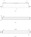
- Fig.8 shows a front view of the interior of the battery unit
- Fig.9 shows a schematic diagram of a state in which a D-D location is sectioned and the tab are not folded back in Fig.8 , at this time, the tab 11 is attached with the outer side faces of the supporting plates 52 and is perpendicular to the guiding plate 51.
- Fig.10 shows a D-D sectional view in Fig.8 and is a schematic diagram of a state in which the supporting plate 52 and the tab 11 are folded back.
- the supporting plate 52 is only arranged on one side of the guiding plate 51 along the width direction.
- the reinforcement portion includes a rib 511, the rib 511 extends along the height direction of the electrode assembly 1 or obliquely extends relative to the height direction, so as to increase the moment of inertia of a section of the guiding plate 51 perpendicular to the height direction of the electrode assembly 1 to the z axis, therefore the bending rigidity of the section of the guiding plate 51 perpendicular to the height direction of the electrode assembly 1 is increased.
- the rib 511 extending along the height direction can achieve a better reinforcement effect, and the rib 511 can adopt a continuous structure or a discontinuous structure.
- the reinforcement portion can also include a plurality of small projections arranged according to a preset rule, etc.
- the reinforcement portion includes one rib 511 or a plurality of ribs 511 arranged at intervals, all the ribs 511 are independently arranged, all the ribs 511 can be arranged in parallel along the vertical direction, so that the sectional bending rigidity of the current collecting member on the height direction is relatively uniform, the overall bending deformation amount can be reduced, and the processing difficulty is low.
- the guiding plate 51 is provided with three ribs 511 which are arranged in parallel along the vertical direction.
- the reinforcement portion includes a plurality groups of ribs 511, wherein the ribs 511 in each group are arranged at intervals, and at least two groups of ribs 511 are arranged staggered, for example, all the ribs 511 form transversely staggered or obliquely interlaced grid-like ribs.
- one side of the reinforcement portion such as the rib 511 away from the electrode assembly 1 protrudes outward relative to the guiding plate 51.
- This structure can reduce the space occupied by the reinforcement portion on one side towards the electrode assembly 1, and reduce the deformation amount of the current collecting member without reducing the energy density of the main body portion.
- the reinforcement portion can also protrude toward one side of the electrode assembly 1.
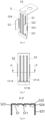
- Fig.13 is a front view of the current collecting member
- Fig.14 is an E-E section view of Fig.13
- one side of the rib 511 close to the electrode assembly 1 depresses inward relative to the guiding plate 51.
- the electrolyte generates a gas, after the gas is discharged from the both sides of the electrode assembly 1 along the length direction, the gas flows along a flow path formed by the depression portion of the rib 511 and is discharged from upper and lower locations of the current collecting member, and the depression portion can also buffer the gas discharged from the both sides of the electrode assembly 1, so that the gas in the electrolyte can smoothly escape, bubbles in the electrolyte can be reduced, and a lithium separation phenomenon of the battery unit is prevented.
- the reinforcement portion crosses the tab 11 along the height area.
- the top of the rib 511 is higher than the top of the tab 11, and the bottom of the rib 511 is lower than the bottom of the tab 11.
- This structure can increase the sectional bending rigidity of the guiding plate 51 as much as possible, and when the tab 11 and the supporting plate 52 are flattened by the flat plate structure, the deformation amount of the guiding plate 51 towards the main body portion 12 can be reduced as much as possible.
- the supporting plate 52 includes a connecting portion 521 and a bending portion 522, the bending portion 522 is connected with the guiding plate 51 and is bent into an arc shape, the tab 11 is connected to the connecting portion 521, and is entirely folded back to one side of the guiding plate 51 away from the main body portion 12 along the outer surfaces of the bending portion 522 and the connecting portion 521.
- the tab 11 bent inward the additional space occupied by the supporting plate 52 on the width direction of the electrode assembly 1 can be avoided, the width size of the battery unit depends on the width of the main body portion 12, so the width size of the battery unit is reduced.
- the rib 511 includes a first rib 511A , the first rib 511A is covered by the connecting portion 521 on the width direction, the first rib 511A has a first protruding height h 1 relative to the guiding plate 51, the bending portion has a third protruding height h 3 relative to the guiding plate 51, and the first protruding height h 1 is less than or equal to the third protruding height h 3 .
- This structure can prevent the connecting portion 521 from tilting up obliquely, so as to avoid the additional space occupied by the current collecting member on the side of the main body portion 12 along the length direction, thus the electrode assembly 1 can be conveniently installed in the shell 8, and an insulating plate can also be conveniently arranged on the outer side face of the tab 11.
- the rib 511 further includes a second rib 511B, the first rib 511A is provided with two segments, the two segments of first rib 511A are covered by different connecting portions 521, the second rib 511B is located between the two segments of first rib 511A, and the second rib 511B is located in an interval area of the two connecting portions 521.
- This structure can prevent the second rib 511B from overlapping with the connecting portion 521, and can reduce the occupied space.
- the second rib 511B has a second protruding height h 2 relative to the guiding plate 51, and the second protruding height h 2 is greater than or equal to the first protruding height.
- one first rib 511A, the second rib 511B and the other first rib 511A are arranged side by side along the width direction, the first protruding heights of the two first ribs 511A are 0 ⁇ h 1 ⁇ 2 mm, preferably 0.3 ⁇ h 1 ⁇ 0.9mm, the second protruding height of the second rib 511B is 0 ⁇ h 2 ⁇ 3mm, preferably 0.3 ⁇ h 2 ⁇ 2 mm, and it is necessary to consider both space and reinforcement effects during the design of the first protruding height and the second protruding height.
- the second rib 511B located in the interval area of the two supporting plates 52 is designed to have a greater protruding height, so that the bending rigidity of an intermediate area of the guiding plate 51 along the width direction can be increased as much as possible, thereby further reducing the deformation amount of the guiding plate 51, and also preventing the tab 11 from tilting up obliquely after being bent.
- the first rib 511A covered by the bent supporting plate 52 is designed to have a smaller protruding height, so that the size occupied by the current collecting member on the side of the electrode assembly 1 can be reduced as much as possible while ensuring the bending rigidity of the guiding plate 51, and in the case that the size of the battery unit is constant, the energy density of the electrode assembly can be increased.
- the first current collecting member 5 and the second current collecting member 6 are designed as different structures.
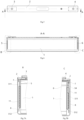
- Fig.5 is a top view of the battery unit of the present disclosure
- the sectional view as shown in Fig.6 is formed after being sectioned along an A-A section in Fig.5
- side view of the first current collecting member 5 and the second current collecting member 6 is illustrated.
- Fig.7A is an enlarged view of a location B of Fig.6 .
- the battery unit further includes a top cover plate 2 and an insulator 7, the electrode terminals are arranged on the top cover plate 2, and the insulator 7 is arranged between the top cover plate 2 and the electrode assembly 1.
- the two current collecting members include a first current collecting member 5 located on one side of the electrode assembly 1, the two electrode terminals include a negative terminal 3, the first current collecting member 5 connects the tab 11 on the same side with the negative terminal 3, the reinforcement portion of the first current collecting member 5 extends to the bottom of the insulator 7 along the height direction.
- This structure can lengthen the length of the reinforcement portion such as the rib 511 along the height direction as much as possible while ensuring that the reinforcement portion does not interfere with the insulator 7, thereby increasing the overall rigidity of the current collecting member along the height direction, and maximally reducing the deformation amount when the tab 11 is flattened.
- the supporting portion 52 partially covers the rib 511 on the height direction.
- the current collecting member further includes a clamping portion 512, the clamping portion 512 is arranged at the bottom of the guiding plate 51 and entirely protrudes toward the side away from the electrode assembly 1.
- the bottom end of the reinforcement portion extends downward to the top end of the clamping portion 512, and the bottom end of the clamping portion 512 is a free end and remains a protruding height.
- a tool can be arranged between the clamping portion 512 and the electrode assembly 1 to reduce the deformation amount of the guiding plate 51 towards the main body portion 12 when the tab 11 is flattened.
- the rib 511 protrudes towards one side away from the electrode assembly 1 relative to the plane of the guiding plate 51, the rib 511 extends along the height direction of the guiding plate 51, the top end of the rib 511 extends upward to the bottom surface of the insulator 7, and the bottom end of the rib 511 extends downward to be connected to the clamping portion 512.
- This structure can maximally increase the length of the rib 511 along the height direction, thereby increasing the rigidity of the first current collecting member 5 on the entire height direction, and maximally reducing the deformation amount when the tab 11 is flattened.
- the surface of the clamping portion 512 away from the guiding plate 51 is not higher than the surface of the tab 11 away from the guiding plate 51 after being folded back.
- This structure does not additionally increase the size of the battery unit along the length direction in the case that the clamping portion 512 is provided; and furthermore, when the insulating plate is arranged on the side of the electrode assembly 1 along the length direction, the insulating plate can also be attached with the tab 11, thereby improving the insulating reliability, and the insulating plate can be installed more firmly by increasing the fitting area of the insulating plate.
- the two current collecting members include a second current collecting member 6 located on the other side of the electrode assembly 1, the two electrode terminals include a positive terminal 4, the second current collecting member 6 connects the tab 11 on the same side to the positive terminal 4, the second current collecting member 6 further includes a heat dissipation portion 54, and the heat dissipation portion 54 is arranged in an area of the guiding plate 51 above the tab 11.
- the second current collecting member 6 and the positive terminal 4 are generally made of an aluminum material
- the first current collecting member 5 and the negative terminal 3 are generally made of a copper material
- the heat dissipation performance of aluminum is inferior to that of the copper
- the heat dissipation portion 54 the heat release can be accelerated, the situation that a local temperature of the second current collecting member 6 is too high to affect the battery performance is avoided, and the working safety of the battery unit is improved.
- the heat dissipation portion 54 the effect of improving the rigidity of the second current collecting member 6 can also be achieved.
- the heat dissipation portion 54 includes a thickened portion, and the thickened portion is arranged on the side of the guiding plate 51 away from the electrode assembly 1.
- a heat dissipation rib or the like can be arranged on the thickened portion to further optimize the heat dissipation effect by increasing the heat dissipation surface.
- the protruding direction of the reinforcement portion and the thickened portion is the same with respect to the guiding plate 51, so that the occupation space of the second current collecting member 6 on the length direction can be reduced to improve the energy density of the battery unit.
- the thickened portion can adopt a rectangular platy structure and is located in an upper area of the guiding plate 51, the width of the thickened portion is adapted to the width of the guiding plate 51 to optimize the heat dissipation effect by increasing the heat dissipation surface area.
- the thickened portion can be connected to the guiding plate 51 by welding, or the thickened portion can be attached and fixed with the guiding plate 51 by folding.
- the reinforcement portion of the second current collecting member 6 extends to the bottom surface of the heat dissipation portion 54 along the height direction.
- the top end of the rib 511 extends to the vicinity of the bottom of the thickened portion, and the bottom end of the rib 511 extends to the vicinity of the clamping portion 512.
- This structure can simultaneously consider the heat dissipation and rigidity of the second current collecting member 6, and on the basis of ensuring the heat dissipation effect, the length of the rib 511 along the height direction can be maximized, thereby improving the rigidity of the first current collecting member 5 and reducing the deformation amount when the tabs 11 are flattened.
- the bending portion 522 is provided with at least one of a slot 523 and a groove 524 extending along the height direction, the slot 523 is formed in an intermediate area of the bending portion 522 along the height direction, for example, an elongated rectangular groove extending along the height direction is adopted, since the stress area is reduced, the strength of the bending portion 522 can be reduced under a constant pressure, the stress generated during the bending is smaller, and the size of the slot 523 should not be too small to ensure the overflow requirements of the current collecting member.
- the groove 524 is formed on the inner side of the bending portion 522 and is located in at least one of an area above the slot 523 and an area below the slot 523, for example, the groove is a nick that is arranged on the inner side of the bending portion 522 and extend along the height direction, and the nick can assist in weakening the strength of the bent area and can accurately locate the bent location.
- Fig.17 is a front view of the current collecting member
- Fig.18 is an F-F section view in Fig.17 .
- This structure can reduce the strength of the supporting plate 52 in the bent area, so as to make the supporting plate 52 of the current collecting member can be fold back easily, and can prevent the stress applied to the bent area from being transferred to other areas of the current collecting member as much as possible in a folding back process, so as to protect the mechanical damage to the electrode assembly 1 and to improve the electrochemical performance in the battery unit.
- the advantages analyzed is made by comparing experimental data.
- the following experimental data are given for the embodiments in which the current collecting members are arranged on the both sides of the supporting plates 52.
- pre-folding and final folding are included, the pre-folding is to fold the supporting plates 52 perpendicular to the guiding plate 51 inward for partial angles, and the final folding is to continue to fold back the supporting plates 52 inward in place.
- the deformation amount of the intermediate area of the guiding plate 51 along the height direction is detected by using a dial indicator.
- a Base group the reinforcement portion is not arranged on the guiding plate 51 of the current collecting member, and only the clamping portions are arranged on the upper and lower areas of the tab 11; in a group A, three segments of ribs 511 are arranged on the outer side face of the guiding plate 51 along the height direction, and the ribs 511 extend to locations adjacent to the upper and lower clamping portions; a group B is compared with the A group and the difference lies in that the thickened portion is arranged on the outer side face of the top area of the guiding plate 51 to serve as the heat dissipation portion 54; and a group C is compared with the A group and the difference lies in that the slot 523 is formed in the bent area of the supporting plate 52.
- Table 1 shows deformation amounts of the first current collecting member 5 and the second current collecting member 6 toward the electrode assembly 1 after being folded back.
- Table 1 Deformation amount of the current collecting member in the folding back process
- First current collecting member 5 /mm Second current collecting member 6 /mm Pre-folding Final folding Pre-folding Final folding
- Base group 1.80 1.99 2.10 2.21
- Group A 1.17 1.32 1.30 1.35
- Group B 1.08 1.09 0.96 0.93
- Group C 0.71 0.31 0.49 0.35
- the deformation amount of the guiding plates 51 in the two current collecting members can be reduced by adding the ribs 511 in the group A; on the basis of the group A, the deformation amount of the guiding plates 51 can be further reduced by replacing the upper clamping portion with the heat dissipation portion 54 in the group B; and on the basis of the group A, the deformation amount of the guiding plates 51 can be further reduced by adding the slot 523 in the group C. It can be found by comparison that the ribs 511 have the most significant effect of reducing the deformation amount of the guiding plates 51.
- the ribs 511, the heat dissipation portion 54 and the slot 523 can be set at the same time to maximally reduce the deformation amount of the guiding plates 51; or, in other embodiments, one of the heat dissipation portion 54 and the slot 523 can be set on the basis of the rib 511.
- the variance of the deformation amount of the guiding plate 51 is given below by table 2 by testing the plurality of battery units.
- Table 2 Standard difference of the deformation amount of the guiding plate 51 of the current collecting member after being folded back Group First current collecting member 5 Second current collecting member 6 Base group 0.23 0.34 Group A 0.18 0.28 Group B 0.05 0.17 Group C 0.07 0.16
- the variance of the deformation amount of the guiding plates 51 in the two current collecting members can be reduced by adding the ribs 511 in the group A; on the basis of the group A, the variance of the deformation amount is further reduced by replacing the upper clamping portion by the heat dissipation portion 54 in the group B; and on the basis of the group A, the variance of the deformation amount is further reduced by adding the slot 523 in the group C. Therefore, by means of the structural improvement of the present disclosure, the deformation amount of the guiding plate 51 can be relatively stable, the precision requirements on a tool fixture can be reduced, and the stability of the batch production can be improved.
Landscapes
- Chemical & Material Sciences (AREA)
- Chemical Kinetics & Catalysis (AREA)
- Electrochemistry (AREA)
- General Chemical & Material Sciences (AREA)
- Connection Of Batteries Or Terminals (AREA)
- Secondary Cells (AREA)
Claims (15)
- Batteriemodul, umfassend:eine Elektrodenanordnung (1), umfassend einen Hauptkörperabschnitt (12) und eine Lasche (11), die sich von einem Ende des Hauptkörperabschnitts (12) entlang einer Längsrichtung der Elektrodenanordnung (1) erstreckt;zwei an der Oberseite der Elektrodenanordnung (1) angeordnete Elektrodenanschlüsse; undzwei Stromabnehmerelemente, die jeweils die Laschen (11) auf beiden Seiten des Hauptkörperabschnitts (12) mit dem jeweiligen Elektrodenanschluss auf der gleichen Seite elektrisch verbinden;wobei jedes Stromabnehmerelement eine Führungsplatte (51) und eine Stützplatte (52) umfasst, wobei die Führungsplatte (51) auf einer Seite des Hauptkörperabschnitts (12) entlang der Längsrichtung angeordnet ist und sich entlang einer Breitenrichtung der Elektrodenanordnung (1) erstreckt, ein Verstärkungsabschnitt auf der Führungsplatte (51) angeordnet und zum Verringern der Verformung der Führungsplatte (51) in Richtung des Hauptkörperabschnitts (12) konfiguriert ist; und die Stützplatte (52) entlang der Breitenrichtung mit einem Ende der Führungsplatte (51) verbunden ist und die Lasche (11) relativ zur Längsrichtung gebogen und mit der Stützplatte (52) verbunden ist.
- Batterieeinheit nach Anspruch 1, wobei der Verstärkungsabschnitt eine Rippe (511) umfasst und sich die Rippe (511) entlang einer Höhenrichtung der Elektrodenanordnung (1) erstreckt oder sich schräg zur Höhenrichtung erstreckt.
- Batterieeinheit nach Anspruch 2, wobei der Verstärkungsabschnitt eine Vielzahl von in Abständen angeordnete Rippen (511) umfasst; oder der Verstärkungsabschnitt eine Vielzahl von Gruppen von Rippen (511) umfasst, wobei die Rippen (511) in jeder Gruppe in Abständen angeordnet sind und mindestens zwei Gruppen von Rippen (511) versetzt angeordnet sind.
- Batterieeinheit nach Anspruch 2, wobei eine Seite der Rippe (511) neben der Elektrodenanordnung (1) relativ zur Führungsplatte (51) nach innen vertieft ist.
- Batterieeinheit nach Anspruch 1, wobei eine Seite des Verstärkungsabschnitts von der Elektrodenanordnung (1) weg relativ zur Führungsplatte (51) nach außen vorsteht.
- Batterieeinheit nach Anspruch 5, wobei die Stützplatte (52) einen Verbindungsabschnitt (521) und einen Biegeabschnitt (522) umfasst, wobei der Biegeabschnitt (522) mit der Führungsplatte (51) verbunden und in eine Bogenform gebogen ist, und die Lasche (11) mit dem Verbindungsabschnitt (521) verbunden und vollständig entlang der Oberfläche des Biegeabschnitts (522) zu einer Seite der Führungsplatte (51) weg vom Hauptkörperabschnitt (12) gefaltet ist.
- Batterieeinheit nach Anspruch 6, wobei der Verstärkungsabschnitt eine Rippe (511) umfasst, die Rippe (511) eine erste Rippe (511A) umfasst, die erste Rippe (511A) durch den Verbindungsabschnitt (521) in Breitenrichtung bedeckt ist, die erste Rippe (511A) eine erste Überstandshöhe h1 relativ zur Führungsplatte (51) aufweist, der Biegeabschnitt (522) eine dritte Überstandshöhe h3 relativ zur Führungsplatte (51) aufweist und die erste Überstandshöhe h1 kleiner oder gleich der dritten Überstandshöhe h3 ist.
- Batterieeinheit nach Anspruch 7, wobei zwei Stützplatten (52) jeweils mit den zwei Enden der Führungsplatte (51) entlang der Breitenrichtung verbunden und zueinander hin gebogen sind, und die Verbindungsabschnitte (521) der zwei Stützplatten (52) in Abständen entlang der Breitenrichtung angeordnet sind; und
die Rippen (511) ferner eine zweite Rippe (511B) umfassen, zwei Segmente der ersten Rippe (511A) von den zwei Verbindungsabschnitten (521) bedeckt sind, die zweite Rippe (511B) zwischen den zwei Segmenten der ersten Rippe (511A) angeordnet ist und sich die zweite Rippe (511B) in einem Intervallbereich der zwei Verbindungsabschnitte (521) befindet. - Batterieeinheit nach Anspruch 8, wobei die zweite Rippe (511B) eine zweite Überstandshöhe h2 relativ zur Führungsplatte (51) aufweist und die zweite Überstandshöhe h2 größer oder gleich der ersten Überstandshöhe h1 ist.
- Batterieeinheit nach einem der Ansprüche 6-9, wobei der Biegeabschnitt (522) mit mindestens einem von einem Schlitz (523) und einer Nut (524) versehen ist, die sich entlang einer Höhenrichtung der Elektrodenanordnung (1) erstrecken, der Schlitz (523) in einem Zwischenbereich des Biegeabschnitts (522) entlang der Höhenrichtung angeordnet ist und die Nut (524) auf einer Innenseite des Biegeabschnitts (522) angeordnet ist und sich in mindestens einem von einem Bereich über dem Schlitz (523) und einem Bereich unter dem Schlitz (523) befindet.
- Batterieeinheit nach einem der Ansprüche 1-10, wobei der Verstärkungsabschnitt die Stützplatte (52) entlang einer Höhenrichtung der Elektrodenanordnung (1) kreuzt.
- Batterieeinheit nach einem der Ansprüche 1-11, ferner umfassend eine obere Deckplatte (2) und einen Isolator (7), der zwischen der oberen Deckplatte (2) und der Elektrodenanordnung (1) angeordnet ist, wobei die Elektrodenanschlüsse auf der oberen Deckplatte (2) angeordnet sind; und
die zwei Stromabnehmerelemente ein erstes Stromabnehmerelement (5) umfassen, das sich auf einer Seite der Elektrodenanordnung (1) befindet, die zwei Elektrodenanschlüsse einen negativen Anschluss (3) umfassen, das erste Stromabnehmerelement (5) die Lasche (11) auf der gleichen Seite mit dem negativen Anschluss (3) verbindet und sich der Verstärkungsabschnitt des ersten Stromabnehmerelements (5) zum Boden des Isolators (7) entlang einer Höhenrichtung der Elektrodenanordnung (1) erstreckt. - Batterieeinheit nach einem der Ansprüche 1-12, wobei die zwei Stromabnehmerelemente ein zweites Stromabnehmerelement (6) umfassen, das sich auf einer Seite der Elektrodenanordnung (1) befindet, die zwei Elektrodenanschlüsse einen positiven Anschluss (4) umfassen, das zweite Stromabnehmerelement (6) die Lasche (11) auf der gleichen Seite mit dem positiven Anschluss (4) verbindet, das zweite Stromabnehmerelement (6) ferner einen Wärmeableitungsabschnitt (54) umfasst, der in einem Bereich der Führungsplatte (51) angeordnet ist, der sich über der Stützplatte (52) befindet;
wobei sich der Verstärkungsabschnitt des zweiten Stromabnehmerelements (6) entlang einer Höhenrichtung der Elektrodenanordnung (1) zum Boden des Wärmeableitungsabschnitts (54) erstreckt. - Batterieeinheit nach einem der Ansprüche 1-13, wobei das Stromabnehmerelement ferner einen Klemmabschnitt (512) umfasst und der Klemmabschnitt (512) an der Unterseite der Führungsplatte (51) angeordnet ist und von der Elektrodenanordnung (1) weg vollständig zu einer Seite hin vorsteht;
wobei die der Führungsplatte (51) ferne Oberfläche des Klemmabschnitts (512) entlang der Längsrichtung nicht höher als die der Führungsplatte (51) ferne Oberfläche der Lasche (11) nach dem Zurückfalten ist. - Batteriemodul, umfassend:
eine Vielzahl von Batterieeinheiten nach einem der Ansprüche 1-14, wobei die Batterieeinheiten entlang der Breitenrichtung Seite an Seite angeordnet sind.
Applications Claiming Priority (1)
| Application Number | Priority Date | Filing Date | Title |
|---|---|---|---|
| CN201910337415.0A CN111864172B (zh) | 2019-04-25 | 2019-04-25 | 电池单元和电池模组 |
Publications (2)
| Publication Number | Publication Date |
|---|---|
| EP3731318A1 EP3731318A1 (de) | 2020-10-28 |
| EP3731318B1 true EP3731318B1 (de) | 2023-07-05 |
Family
ID=69055780
Family Applications (1)
| Application Number | Title | Priority Date | Filing Date |
|---|---|---|---|
| EP19219899.2A Active EP3731318B1 (de) | 2019-04-25 | 2019-12-27 | Batterieeinheit und batteriemodul |
Country Status (7)
| Country | Link |
|---|---|
| US (1) | US11936049B2 (de) |
| EP (1) | EP3731318B1 (de) |
| JP (1) | JP7434350B2 (de) |
| CN (1) | CN111864172B (de) |
| HU (1) | HUE063147T2 (de) |
| PL (1) | PL3731318T3 (de) |
| WO (1) | WO2020215919A1 (de) |
Families Citing this family (21)
| Publication number | Priority date | Publication date | Assignee | Title |
|---|---|---|---|---|
| JP7304372B2 (ja) * | 2021-01-28 | 2023-07-06 | プライムプラネットエナジー&ソリューションズ株式会社 | 二次電池 |
| CN112803121B (zh) * | 2021-02-19 | 2024-04-26 | 大连中比动力电池有限公司 | 电芯的汇流组件和模组 |
| CN112563560B (zh) * | 2021-02-23 | 2021-05-18 | 江苏时代新能源科技有限公司 | 电池单体、电池、用电装置及电池单体的制造方法 |
| CN112701422B (zh) * | 2021-03-24 | 2022-01-07 | 江苏时代新能源科技有限公司 | 电池单体、电池及用电设备 |
| CN113851788A (zh) * | 2021-08-19 | 2021-12-28 | 湖北亿纬动力有限公司 | 连接结构及电池 |
| CN217134598U (zh) * | 2022-04-07 | 2022-08-05 | 远景动力技术(江苏)有限公司 | 一种转接片、电池单元及电子设备 |
| CN115064701B (zh) * | 2022-05-20 | 2025-02-11 | 远景动力技术(江苏)有限公司 | 一种集流构件和电池制造方法 |
| CN115241610A (zh) * | 2022-05-20 | 2022-10-25 | 远景动力技术(江苏)有限公司 | 一种集流构件、电池单元及电子设备 |
| CN114744373A (zh) * | 2022-05-20 | 2022-07-12 | 远景动力技术(江苏)有限公司 | 一种电池制造方法 |
| CN115064749B (zh) * | 2022-05-20 | 2026-03-31 | 远景动力技术(江苏)有限公司 | 一种电池装配方法及集流构件 |
| CN118451602B (zh) * | 2022-08-05 | 2025-12-12 | 宁德时代新能源科技股份有限公司 | 电池单体、电池以及用电装置 |
| JP7827588B2 (ja) * | 2022-08-31 | 2026-03-10 | トヨタバッテリー株式会社 | 電池 |
| CN115939688B (zh) * | 2022-12-28 | 2026-04-14 | 株式会社Aesc日本 | 电芯结构、电池模块及电池包 |
| US20240222806A1 (en) * | 2022-12-30 | 2024-07-04 | Aesc Japan Ltd. | Pin structure and battery cell assembly |
| CN116031580A (zh) * | 2023-01-31 | 2023-04-28 | 湖北亿纬动力有限公司 | 一种电池引脚及电池 |
| CN116231233A (zh) * | 2023-03-07 | 2023-06-06 | 湖北亿纬动力有限公司 | 一种引脚及电芯结构 |
| WO2024183126A1 (zh) * | 2023-03-07 | 2024-09-12 | 湖北亿纬动力有限公司 | 一种引脚及电芯结构 |
| SE2350757A1 (en) * | 2023-06-20 | 2024-12-21 | Northvolt Ab | Current collector for battery cell |
| CN117832772A (zh) * | 2023-12-29 | 2024-04-05 | 惠州亿纬动力电池有限公司 | 集流件及电池 |
| EP4589756A1 (de) * | 2024-01-17 | 2025-07-23 | Automotive Cells Company SE | Kollektorplatte für eine batteriezelle |
| WO2025234320A1 (ja) * | 2024-05-07 | 2025-11-13 | 株式会社Honda・GS Yuasa EV Battery R&D | 蓄電素子 |
Family Cites Families (31)
| Publication number | Priority date | Publication date | Assignee | Title |
|---|---|---|---|---|
| KR20030066172A (ko) * | 2002-02-05 | 2003-08-09 | 삼성에스디아이 주식회사 | 전극 탭 및 이를 구비한 밀폐전지 |
| US7718312B2 (en) * | 2002-05-27 | 2010-05-18 | Gs Yuasa Corporation | Battery |
| JP4514434B2 (ja) | 2003-11-06 | 2010-07-28 | 三洋電機株式会社 | 二次電池 |
| US8268478B2 (en) * | 2009-08-17 | 2012-09-18 | Sb Limotive Co., Ltd. | Rechargeable battery having anti-vibration member |
| WO2011046319A2 (ko) * | 2009-10-13 | 2011-04-21 | 주식회사 엘지화학 | 구조적 안정성이 우수한 전지모듈 |
| KR101222247B1 (ko) * | 2010-12-24 | 2013-01-16 | 로베르트 보쉬 게엠베하 | 이차전지 |
| JP5663415B2 (ja) | 2011-06-24 | 2015-02-04 | 日立オートモティブシステムズ株式会社 | 二次電池 |
| US9287550B2 (en) * | 2012-06-11 | 2016-03-15 | Samsung Sdi Co., Ltd. | Rechargeable battery |
| KR101675621B1 (ko) * | 2013-04-18 | 2016-11-11 | 삼성에스디아이 주식회사 | 이차 전지 |
| KR101675623B1 (ko) | 2013-10-17 | 2016-11-11 | 삼성에스디아이 주식회사 | 이차 전지 및 그 제조 방법 |
| KR102306495B1 (ko) * | 2013-12-04 | 2021-09-28 | 가부시키가이샤 한도오따이 에네루기 켄큐쇼 | 축전체 및 전자 기기 |
| KR102348679B1 (ko) * | 2015-02-24 | 2022-01-06 | 삼성에스디아이 주식회사 | 이차 전지 및 그 모듈 |
| KR102483338B1 (ko) * | 2015-05-15 | 2023-01-02 | 삼성에스디아이 주식회사 | 이차 전지 |
| CN108735957B (zh) | 2017-04-19 | 2021-05-04 | 宁德时代新能源科技股份有限公司 | 电池模组 |
| JP6872143B2 (ja) | 2017-04-28 | 2021-05-19 | トヨタ自動車株式会社 | 二次電池および集電端子 |
| KR102450146B1 (ko) | 2017-08-31 | 2022-10-04 | 삼성에스디아이 주식회사 | 이차 전지 |
| KR102571487B1 (ko) | 2017-08-31 | 2023-08-28 | 삼성에스디아이 주식회사 | 이차 전지 및 그 조립 방법 |
| KR102371196B1 (ko) | 2017-08-31 | 2022-03-07 | 삼성에스디아이 주식회사 | 이차 전지 |
| EP3451415B1 (de) | 2017-08-31 | 2020-03-25 | Samsung SDI Co., Ltd. | Sekundärbatterie |
| CN208014793U (zh) * | 2018-01-16 | 2018-10-26 | 宁德时代新能源科技股份有限公司 | 连接构件和充电电池 |
| CN108199072B (zh) | 2018-01-16 | 2020-06-23 | 宁德时代新能源科技股份有限公司 | 充电电池 |
| CN108258180B (zh) | 2018-01-16 | 2020-09-29 | 宁德时代新能源科技股份有限公司 | 集流构件和电池 |
| CN108198989B (zh) | 2018-01-16 | 2021-01-12 | 宁德时代新能源科技股份有限公司 | 连接构件和充电电池 |
| CN108598353B (zh) * | 2018-01-16 | 2020-10-23 | 宁德时代新能源科技股份有限公司 | 充电电池 |
| CN108428921A (zh) * | 2018-02-01 | 2018-08-21 | 宁德时代新能源科技股份有限公司 | 二次电池 |
| CN208507745U (zh) * | 2018-07-13 | 2019-02-15 | 宁德时代新能源科技股份有限公司 | 二次电池 |
| CN109360932B (zh) | 2018-11-19 | 2022-06-14 | 上海电气国轩新能源科技(苏州)有限公司 | 一种用于圆柱全极耳锂离子电池的集流盘 |
| CN111106300B (zh) * | 2019-01-30 | 2021-05-11 | 宁德时代新能源科技股份有限公司 | 电池单元及电池模组 |
| CN209658286U (zh) * | 2019-04-25 | 2019-11-19 | 宁德时代新能源科技股份有限公司 | 电池单元和电池模组 |
| CN111987340B (zh) * | 2019-05-24 | 2024-10-15 | 宁德时代新能源科技股份有限公司 | 电池单元及其制造方法、电池模组 |
| CN209658320U (zh) * | 2019-05-24 | 2019-11-19 | 宁德时代新能源科技股份有限公司 | 电池单元及电池模组 |
-
2019
- 2019-04-25 CN CN201910337415.0A patent/CN111864172B/zh active Active
- 2019-12-27 EP EP19219899.2A patent/EP3731318B1/de active Active
- 2019-12-27 PL PL19219899.2T patent/PL3731318T3/pl unknown
- 2019-12-27 HU HUE19219899A patent/HUE063147T2/hu unknown
-
2020
- 2020-01-02 US US16/732,615 patent/US11936049B2/en active Active
- 2020-03-11 JP JP2021555808A patent/JP7434350B2/ja active Active
- 2020-03-11 WO PCT/CN2020/078804 patent/WO2020215919A1/zh not_active Ceased
Also Published As
| Publication number | Publication date |
|---|---|
| US11936049B2 (en) | 2024-03-19 |
| US20200343559A1 (en) | 2020-10-29 |
| CN111864172A (zh) | 2020-10-30 |
| EP3731318A1 (de) | 2020-10-28 |
| WO2020215919A1 (zh) | 2020-10-29 |
| CN111864172B (zh) | 2025-01-17 |
| JP7434350B2 (ja) | 2024-02-20 |
| JP2022529883A (ja) | 2022-06-27 |
| PL3731318T3 (pl) | 2023-11-27 |
| HUE063147T2 (hu) | 2023-12-28 |
Similar Documents
| Publication | Publication Date | Title |
|---|---|---|
| EP3731318B1 (de) | Batterieeinheit und batteriemodul | |
| CN209658286U (zh) | 电池单元和电池模组 | |
| EP2849262B1 (de) | Batteriezelle mit unregelmassiger struktur und batteriemodul damit | |
| EP3890085A1 (de) | Batteriezellenanordnung, batteriemodul und batteriepack | |
| CN216850226U (zh) | 电池组 | |
| KR20200135847A (ko) | 셀, 파워 배터리 및 전기 자동차 | |
| WO2014137112A1 (ko) | 단차 구조를 포함하는 전지셀 | |
| US20070148542A1 (en) | Battery electrode design and a flat stack battery cell design and methods of making same | |
| EP3799182B1 (de) | Sekundärbatterie, batteriesatz und elektrische vorrichtung | |
| KR20140090459A (ko) | 이차전지 팩 | |
| CN216850253U (zh) | 电池及电池组 | |
| CN216850254U (zh) | 电池及电池组 | |
| KR101907213B1 (ko) | 리브 유니트가 형성된 케이스를 구비하는 배터리 팩 | |
| US9012059B2 (en) | Secondary battery | |
| CN120473620B (zh) | 一种下塑胶、端盖组件、储能装置及用电设备 | |
| CN217086828U (zh) | 电池及电池组 | |
| CN222463330U (zh) | 一种电连接片、电池包以及用电设备 | |
| CN217881827U (zh) | 电池 | |
| CN220627879U (zh) | 电池模组及电池包 | |
| CN217823030U (zh) | 电池盖板组件及电池 | |
| CN219917356U (zh) | 电池 | |
| CN217444461U (zh) | 电池单体、电池包、车辆 | |
| CN217933993U (zh) | 四棱柱型电池 | |
| CN217589368U (zh) | 电池 | |
| CN216980648U (zh) | 电芯单元及电池 |
Legal Events
| Date | Code | Title | Description |
|---|---|---|---|
| PUAI | Public reference made under article 153(3) epc to a published international application that has entered the european phase |
Free format text: ORIGINAL CODE: 0009012 |
|
| STAA | Information on the status of an ep patent application or granted ep patent |
Free format text: STATUS: THE APPLICATION HAS BEEN PUBLISHED |
|
| AK | Designated contracting states |
Kind code of ref document: A1 Designated state(s): AL AT BE BG CH CY CZ DE DK EE ES FI FR GB GR HR HU IE IS IT LI LT LU LV MC MK MT NL NO PL PT RO RS SE SI SK SM TR |
|
| AX | Request for extension of the european patent |
Extension state: BA ME |
|
| STAA | Information on the status of an ep patent application or granted ep patent |
Free format text: STATUS: REQUEST FOR EXAMINATION WAS MADE |
|
| 17P | Request for examination filed |
Effective date: 20210120 |
|
| RBV | Designated contracting states (corrected) |
Designated state(s): AL AT BE BG CH CY CZ DE DK EE ES FI FR GB GR HR HU IE IS IT LI LT LU LV MC MK MT NL NO PL PT RO RS SE SI SK SM TR |
|
| GRAP | Despatch of communication of intention to grant a patent |
Free format text: ORIGINAL CODE: EPIDOSNIGR1 |
|
| STAA | Information on the status of an ep patent application or granted ep patent |
Free format text: STATUS: GRANT OF PATENT IS INTENDED |
|
| RIC1 | Information provided on ipc code assigned before grant |
Ipc: H01M 50/536 20210101ALI20230111BHEP Ipc: H01M 50/20 20210101ALI20230111BHEP Ipc: H01M 4/75 19740701ALI20230111BHEP Ipc: H01M 4/70 19740701AFI20230111BHEP |
|
| INTG | Intention to grant announced |
Effective date: 20230127 |
|
| GRAS | Grant fee paid |
Free format text: ORIGINAL CODE: EPIDOSNIGR3 |
|
| GRAA | (expected) grant |
Free format text: ORIGINAL CODE: 0009210 |
|
| STAA | Information on the status of an ep patent application or granted ep patent |
Free format text: STATUS: THE PATENT HAS BEEN GRANTED |
|
| P01 | Opt-out of the competence of the unified patent court (upc) registered |
Effective date: 20230516 |
|
| AK | Designated contracting states |
Kind code of ref document: B1 Designated state(s): AL AT BE BG CH CY CZ DE DK EE ES FI FR GB GR HR HU IE IS IT LI LT LU LV MC MK MT NL NO PL PT RO RS SE SI SK SM TR |
|
| REG | Reference to a national code |
Ref country code: CH Ref legal event code: EP |
|
| REG | Reference to a national code |
Ref country code: AT Ref legal event code: REF Ref document number: 1585664 Country of ref document: AT Kind code of ref document: T Effective date: 20230715 |
|
| REG | Reference to a national code |
Ref country code: DE Ref legal event code: R096 Ref document number: 602019032074 Country of ref document: DE |
|
| REG | Reference to a national code |
Ref country code: IE Ref legal event code: FG4D |
|
| REG | Reference to a national code |
Ref country code: NL Ref legal event code: FP |
|
| REG | Reference to a national code |
Ref country code: SE Ref legal event code: TRGR |
|
| REG | Reference to a national code |
Ref country code: LT Ref legal event code: MG9D |
|
| REG | Reference to a national code |
Ref country code: AT Ref legal event code: MK05 Ref document number: 1585664 Country of ref document: AT Kind code of ref document: T Effective date: 20230705 |
|
| REG | Reference to a national code |
Ref country code: HU Ref legal event code: AG4A Ref document number: E063147 Country of ref document: HU |
|
| PG25 | Lapsed in a contracting state [announced via postgrant information from national office to epo] |
Ref country code: GR Free format text: LAPSE BECAUSE OF FAILURE TO SUBMIT A TRANSLATION OF THE DESCRIPTION OR TO PAY THE FEE WITHIN THE PRESCRIBED TIME-LIMIT Effective date: 20231006 |
|
| PG25 | Lapsed in a contracting state [announced via postgrant information from national office to epo] |
Ref country code: ES Free format text: LAPSE BECAUSE OF FAILURE TO SUBMIT A TRANSLATION OF THE DESCRIPTION OR TO PAY THE FEE WITHIN THE PRESCRIBED TIME-LIMIT Effective date: 20230705 |
|
| PG25 | Lapsed in a contracting state [announced via postgrant information from national office to epo] |
Ref country code: IS Free format text: LAPSE BECAUSE OF FAILURE TO SUBMIT A TRANSLATION OF THE DESCRIPTION OR TO PAY THE FEE WITHIN THE PRESCRIBED TIME-LIMIT Effective date: 20231105 |
|
| PG25 | Lapsed in a contracting state [announced via postgrant information from national office to epo] |
Ref country code: RS Free format text: LAPSE BECAUSE OF FAILURE TO SUBMIT A TRANSLATION OF THE DESCRIPTION OR TO PAY THE FEE WITHIN THE PRESCRIBED TIME-LIMIT Effective date: 20230705 Ref country code: PT Free format text: LAPSE BECAUSE OF FAILURE TO SUBMIT A TRANSLATION OF THE DESCRIPTION OR TO PAY THE FEE WITHIN THE PRESCRIBED TIME-LIMIT Effective date: 20231106 Ref country code: NO Free format text: LAPSE BECAUSE OF FAILURE TO SUBMIT A TRANSLATION OF THE DESCRIPTION OR TO PAY THE FEE WITHIN THE PRESCRIBED TIME-LIMIT Effective date: 20231005 Ref country code: LV Free format text: LAPSE BECAUSE OF FAILURE TO SUBMIT A TRANSLATION OF THE DESCRIPTION OR TO PAY THE FEE WITHIN THE PRESCRIBED TIME-LIMIT Effective date: 20230705 Ref country code: LT Free format text: LAPSE BECAUSE OF FAILURE TO SUBMIT A TRANSLATION OF THE DESCRIPTION OR TO PAY THE FEE WITHIN THE PRESCRIBED TIME-LIMIT Effective date: 20230705 Ref country code: IS Free format text: LAPSE BECAUSE OF FAILURE TO SUBMIT A TRANSLATION OF THE DESCRIPTION OR TO PAY THE FEE WITHIN THE PRESCRIBED TIME-LIMIT Effective date: 20231105 Ref country code: HR Free format text: LAPSE BECAUSE OF FAILURE TO SUBMIT A TRANSLATION OF THE DESCRIPTION OR TO PAY THE FEE WITHIN THE PRESCRIBED TIME-LIMIT Effective date: 20230705 Ref country code: GR Free format text: LAPSE BECAUSE OF FAILURE TO SUBMIT A TRANSLATION OF THE DESCRIPTION OR TO PAY THE FEE WITHIN THE PRESCRIBED TIME-LIMIT Effective date: 20231006 Ref country code: FI Free format text: LAPSE BECAUSE OF FAILURE TO SUBMIT A TRANSLATION OF THE DESCRIPTION OR TO PAY THE FEE WITHIN THE PRESCRIBED TIME-LIMIT Effective date: 20230705 Ref country code: ES Free format text: LAPSE BECAUSE OF FAILURE TO SUBMIT A TRANSLATION OF THE DESCRIPTION OR TO PAY THE FEE WITHIN THE PRESCRIBED TIME-LIMIT Effective date: 20230705 Ref country code: AT Free format text: LAPSE BECAUSE OF FAILURE TO SUBMIT A TRANSLATION OF THE DESCRIPTION OR TO PAY THE FEE WITHIN THE PRESCRIBED TIME-LIMIT Effective date: 20230705 |
|
| REG | Reference to a national code |
Ref country code: DE Ref legal event code: R097 Ref document number: 602019032074 Country of ref document: DE |
|
| PG25 | Lapsed in a contracting state [announced via postgrant information from national office to epo] |
Ref country code: SM Free format text: LAPSE BECAUSE OF FAILURE TO SUBMIT A TRANSLATION OF THE DESCRIPTION OR TO PAY THE FEE WITHIN THE PRESCRIBED TIME-LIMIT Effective date: 20230705 Ref country code: RO Free format text: LAPSE BECAUSE OF FAILURE TO SUBMIT A TRANSLATION OF THE DESCRIPTION OR TO PAY THE FEE WITHIN THE PRESCRIBED TIME-LIMIT Effective date: 20230705 Ref country code: EE Free format text: LAPSE BECAUSE OF FAILURE TO SUBMIT A TRANSLATION OF THE DESCRIPTION OR TO PAY THE FEE WITHIN THE PRESCRIBED TIME-LIMIT Effective date: 20230705 Ref country code: DK Free format text: LAPSE BECAUSE OF FAILURE TO SUBMIT A TRANSLATION OF THE DESCRIPTION OR TO PAY THE FEE WITHIN THE PRESCRIBED TIME-LIMIT Effective date: 20230705 Ref country code: CZ Free format text: LAPSE BECAUSE OF FAILURE TO SUBMIT A TRANSLATION OF THE DESCRIPTION OR TO PAY THE FEE WITHIN THE PRESCRIBED TIME-LIMIT Effective date: 20230705 Ref country code: SK Free format text: LAPSE BECAUSE OF FAILURE TO SUBMIT A TRANSLATION OF THE DESCRIPTION OR TO PAY THE FEE WITHIN THE PRESCRIBED TIME-LIMIT Effective date: 20230705 |
|
| PLBE | No opposition filed within time limit |
Free format text: ORIGINAL CODE: 0009261 |
|
| STAA | Information on the status of an ep patent application or granted ep patent |
Free format text: STATUS: NO OPPOSITION FILED WITHIN TIME LIMIT |
|
| PG25 | Lapsed in a contracting state [announced via postgrant information from national office to epo] |
Ref country code: IT Free format text: LAPSE BECAUSE OF FAILURE TO SUBMIT A TRANSLATION OF THE DESCRIPTION OR TO PAY THE FEE WITHIN THE PRESCRIBED TIME-LIMIT Effective date: 20230705 |
|
| 26N | No opposition filed |
Effective date: 20240408 |
|
| PG25 | Lapsed in a contracting state [announced via postgrant information from national office to epo] |
Ref country code: SI Free format text: LAPSE BECAUSE OF FAILURE TO SUBMIT A TRANSLATION OF THE DESCRIPTION OR TO PAY THE FEE WITHIN THE PRESCRIBED TIME-LIMIT Effective date: 20230705 |
|
| REG | Reference to a national code |
Ref country code: CH Ref legal event code: PL |
|
| REG | Reference to a national code |
Ref country code: DE Ref legal event code: R081 Ref document number: 602019032074 Country of ref document: DE Owner name: CONTEMPORARY AMPEREX TECHNOLOGY (HONG KONG) LI, HK Free format text: FORMER OWNER: CONTEMPORARY AMPEREX TECHNOLOGY CO., LTD., NINGDE CITY, FUJIAN, CN |
|
| PG25 | Lapsed in a contracting state [announced via postgrant information from national office to epo] |
Ref country code: LU Free format text: LAPSE BECAUSE OF NON-PAYMENT OF DUE FEES Effective date: 20231227 |
|
| PG25 | Lapsed in a contracting state [announced via postgrant information from national office to epo] |
Ref country code: MC Free format text: LAPSE BECAUSE OF FAILURE TO SUBMIT A TRANSLATION OF THE DESCRIPTION OR TO PAY THE FEE WITHIN THE PRESCRIBED TIME-LIMIT Effective date: 20230705 |
|
| REG | Reference to a national code |
Ref country code: NL Ref legal event code: PD Owner name: CONTEMPORARY AMPEREX TECHNOLOGY (HONG KONG) LIMITED; CN Free format text: DETAILS ASSIGNMENT: CHANGE OF OWNER(S), ASSIGNMENT; FORMER OWNER NAME: CONTEMPORARY AMPEREX TECHNOLOGY CO., LIMITED Effective date: 20240819 |
|
| REG | Reference to a national code |
Ref country code: BE Ref legal event code: MM Effective date: 20231231 |
|
| PG25 | Lapsed in a contracting state [announced via postgrant information from national office to epo] |
Ref country code: MC Free format text: LAPSE BECAUSE OF FAILURE TO SUBMIT A TRANSLATION OF THE DESCRIPTION OR TO PAY THE FEE WITHIN THE PRESCRIBED TIME-LIMIT Effective date: 20230705 Ref country code: LU Free format text: LAPSE BECAUSE OF NON-PAYMENT OF DUE FEES Effective date: 20231227 |
|
| REG | Reference to a national code |
Ref country code: GB Ref legal event code: 732E Free format text: REGISTERED BETWEEN 20240815 AND 20240821 |
|
| REG | Reference to a national code |
Ref country code: HU Ref legal event code: GB9C Owner name: CONTEMPORARY AMPEREX TECHNOLOGY (HONG KONG) LIMITED, HK Free format text: FORMER OWNER(S): CONTEMPORARY AMPEREX TECHNOLOGY CO., LIMITED, CN Ref country code: HU Ref legal event code: FH1C Free format text: FORMER REPRESENTATIVE(S): SBGK SZABADALMI UEGYVIVOEI IRODA, HU Representative=s name: DANUBIA SZABADALMI ES JOGI IRODA KFT., HU |
|
| REG | Reference to a national code |
Ref country code: IE Ref legal event code: MM4A |
|
| PG25 | Lapsed in a contracting state [announced via postgrant information from national office to epo] |
Ref country code: IE Free format text: LAPSE BECAUSE OF NON-PAYMENT OF DUE FEES Effective date: 20231227 |
|
| PG25 | Lapsed in a contracting state [announced via postgrant information from national office to epo] |
Ref country code: BE Free format text: LAPSE BECAUSE OF NON-PAYMENT OF DUE FEES Effective date: 20231231 |
|
| PG25 | Lapsed in a contracting state [announced via postgrant information from national office to epo] |
Ref country code: CH Free format text: LAPSE BECAUSE OF NON-PAYMENT OF DUE FEES Effective date: 20231231 |
|
| PG25 | Lapsed in a contracting state [announced via postgrant information from national office to epo] |
Ref country code: IE Free format text: LAPSE BECAUSE OF NON-PAYMENT OF DUE FEES Effective date: 20231227 Ref country code: CH Free format text: LAPSE BECAUSE OF NON-PAYMENT OF DUE FEES Effective date: 20231231 Ref country code: BE Free format text: LAPSE BECAUSE OF NON-PAYMENT OF DUE FEES Effective date: 20231231 |
|
| PG25 | Lapsed in a contracting state [announced via postgrant information from national office to epo] |
Ref country code: BG Free format text: LAPSE BECAUSE OF FAILURE TO SUBMIT A TRANSLATION OF THE DESCRIPTION OR TO PAY THE FEE WITHIN THE PRESCRIBED TIME-LIMIT Effective date: 20230705 |
|
| PG25 | Lapsed in a contracting state [announced via postgrant information from national office to epo] |
Ref country code: BG Free format text: LAPSE BECAUSE OF FAILURE TO SUBMIT A TRANSLATION OF THE DESCRIPTION OR TO PAY THE FEE WITHIN THE PRESCRIBED TIME-LIMIT Effective date: 20230705 |
|
| PG25 | Lapsed in a contracting state [announced via postgrant information from national office to epo] |
Ref country code: CY Free format text: LAPSE BECAUSE OF FAILURE TO SUBMIT A TRANSLATION OF THE DESCRIPTION OR TO PAY THE FEE WITHIN THE PRESCRIBED TIME-LIMIT; INVALID AB INITIO Effective date: 20191227 |
|
| PGFP | Annual fee paid to national office [announced via postgrant information from national office to epo] |
Ref country code: NL Payment date: 20251003 Year of fee payment: 7 |
|
| PG25 | Lapsed in a contracting state [announced via postgrant information from national office to epo] |
Ref country code: TR Free format text: LAPSE BECAUSE OF FAILURE TO SUBMIT A TRANSLATION OF THE DESCRIPTION OR TO PAY THE FEE WITHIN THE PRESCRIBED TIME-LIMIT Effective date: 20230705 |
|
| PGFP | Annual fee paid to national office [announced via postgrant information from national office to epo] |
Ref country code: DE Payment date: 20250930 Year of fee payment: 7 |
|
| PGFP | Annual fee paid to national office [announced via postgrant information from national office to epo] |
Ref country code: GB Payment date: 20251001 Year of fee payment: 7 |
|
| PGFP | Annual fee paid to national office [announced via postgrant information from national office to epo] |
Ref country code: HU Payment date: 20251127 Year of fee payment: 7 Ref country code: FR Payment date: 20251110 Year of fee payment: 7 |
|
| PGFP | Annual fee paid to national office [announced via postgrant information from national office to epo] |
Ref country code: SE Payment date: 20251001 Year of fee payment: 7 |
|
| PGFP | Annual fee paid to national office [announced via postgrant information from national office to epo] |
Ref country code: PL Payment date: 20251014 Year of fee payment: 7 |