EP3799182B1 - Sekundärbatterie, batteriesatz und elektrische vorrichtung - Google Patents
Sekundärbatterie, batteriesatz und elektrische vorrichtung Download PDFInfo
- Publication number
- EP3799182B1 EP3799182B1 EP20809286.6A EP20809286A EP3799182B1 EP 3799182 B1 EP3799182 B1 EP 3799182B1 EP 20809286 A EP20809286 A EP 20809286A EP 3799182 B1 EP3799182 B1 EP 3799182B1
- Authority
- EP
- European Patent Office
- Prior art keywords
- flow guiding
- guiding component
- secondary battery
- component
- plates
- Prior art date
- Legal status (The legal status is an assumption and is not a legal conclusion. Google has not performed a legal analysis and makes no representation as to the accuracy of the status listed.)
- Active
Links
Images


Classifications
-
- H—ELECTRICITY
- H01—ELECTRIC ELEMENTS
- H01M—PROCESSES OR MEANS, e.g. BATTERIES, FOR THE DIRECT CONVERSION OF CHEMICAL ENERGY INTO ELECTRICAL ENERGY
- H01M10/00—Secondary cells; Manufacture thereof
- H01M10/04—Construction or manufacture in general
- H01M10/0431—Cells with wound or folded electrodes
-
- H—ELECTRICITY
- H01—ELECTRIC ELEMENTS
- H01M—PROCESSES OR MEANS, e.g. BATTERIES, FOR THE DIRECT CONVERSION OF CHEMICAL ENERGY INTO ELECTRICAL ENERGY
- H01M10/00—Secondary cells; Manufacture thereof
- H01M10/05—Accumulators with non-aqueous electrolyte
- H01M10/052—Li-accumulators
-
- H—ELECTRICITY
- H01—ELECTRIC ELEMENTS
- H01M—PROCESSES OR MEANS, e.g. BATTERIES, FOR THE DIRECT CONVERSION OF CHEMICAL ENERGY INTO ELECTRICAL ENERGY
- H01M10/00—Secondary cells; Manufacture thereof
- H01M10/05—Accumulators with non-aqueous electrolyte
- H01M10/058—Construction or manufacture
- H01M10/0585—Construction or manufacture of accumulators having only flat construction elements, i.e. flat positive electrodes, flat negative electrodes and flat separators
-
- H—ELECTRICITY
- H01—ELECTRIC ELEMENTS
- H01M—PROCESSES OR MEANS, e.g. BATTERIES, FOR THE DIRECT CONVERSION OF CHEMICAL ENERGY INTO ELECTRICAL ENERGY
- H01M50/00—Constructional details or processes of manufacture of the non-active parts of electrochemical cells other than fuel cells, e.g. hybrid cells
- H01M50/10—Primary casings; Jackets or wrappings
- H01M50/102—Primary casings; Jackets or wrappings characterised by their shape or physical structure
- H01M50/103—Primary casings; Jackets or wrappings characterised by their shape or physical structure prismatic or rectangular
-
- H—ELECTRICITY
- H01—ELECTRIC ELEMENTS
- H01M—PROCESSES OR MEANS, e.g. BATTERIES, FOR THE DIRECT CONVERSION OF CHEMICAL ENERGY INTO ELECTRICAL ENERGY
- H01M50/00—Constructional details or processes of manufacture of the non-active parts of electrochemical cells other than fuel cells, e.g. hybrid cells
- H01M50/10—Primary casings; Jackets or wrappings
- H01M50/147—Lids or covers
-
- H—ELECTRICITY
- H01—ELECTRIC ELEMENTS
- H01M—PROCESSES OR MEANS, e.g. BATTERIES, FOR THE DIRECT CONVERSION OF CHEMICAL ENERGY INTO ELECTRICAL ENERGY
- H01M50/00—Constructional details or processes of manufacture of the non-active parts of electrochemical cells other than fuel cells, e.g. hybrid cells
- H01M50/50—Current conducting connections for cells or batteries
- H01M50/531—Electrode connections inside a battery casing
- H01M50/533—Electrode connections inside a battery casing characterised by the shape of the leads or tabs
-
- H—ELECTRICITY
- H01—ELECTRIC ELEMENTS
- H01M—PROCESSES OR MEANS, e.g. BATTERIES, FOR THE DIRECT CONVERSION OF CHEMICAL ENERGY INTO ELECTRICAL ENERGY
- H01M50/00—Constructional details or processes of manufacture of the non-active parts of electrochemical cells other than fuel cells, e.g. hybrid cells
- H01M50/70—Arrangements for stirring or circulating the electrolyte
-
- H—ELECTRICITY
- H01—ELECTRIC ELEMENTS
- H01M—PROCESSES OR MEANS, e.g. BATTERIES, FOR THE DIRECT CONVERSION OF CHEMICAL ENERGY INTO ELECTRICAL ENERGY
- H01M10/00—Secondary cells; Manufacture thereof
- H01M10/05—Accumulators with non-aqueous electrolyte
- H01M10/058—Construction or manufacture
- H01M10/0587—Construction or manufacture of accumulators having only wound construction elements, i.e. wound positive electrodes, wound negative electrodes and wound separators
-
- Y—GENERAL TAGGING OF NEW TECHNOLOGICAL DEVELOPMENTS; GENERAL TAGGING OF CROSS-SECTIONAL TECHNOLOGIES SPANNING OVER SEVERAL SECTIONS OF THE IPC; TECHNICAL SUBJECTS COVERED BY FORMER USPC CROSS-REFERENCE ART COLLECTIONS [XRACs] AND DIGESTS
- Y02—TECHNOLOGIES OR APPLICATIONS FOR MITIGATION OR ADAPTATION AGAINST CLIMATE CHANGE
- Y02E—REDUCTION OF GREENHOUSE GAS [GHG] EMISSIONS, RELATED TO ENERGY GENERATION, TRANSMISSION OR DISTRIBUTION
- Y02E60/00—Enabling technologies; Technologies with a potential or indirect contribution to GHG emissions mitigation
- Y02E60/10—Energy storage using batteries
-
- Y—GENERAL TAGGING OF NEW TECHNOLOGICAL DEVELOPMENTS; GENERAL TAGGING OF CROSS-SECTIONAL TECHNOLOGIES SPANNING OVER SEVERAL SECTIONS OF THE IPC; TECHNICAL SUBJECTS COVERED BY FORMER USPC CROSS-REFERENCE ART COLLECTIONS [XRACs] AND DIGESTS
- Y02—TECHNOLOGIES OR APPLICATIONS FOR MITIGATION OR ADAPTATION AGAINST CLIMATE CHANGE
- Y02P—CLIMATE CHANGE MITIGATION TECHNOLOGIES IN THE PRODUCTION OR PROCESSING OF GOODS
- Y02P70/00—Climate change mitigation technologies in the production process for final industrial or consumer products
- Y02P70/50—Manufacturing or production processes characterised by the final manufactured product
Definitions
- the present application relates to the technical field of energy storage devices, and in particular, to a secondary battery, a battery pack and an electric device.
- a secondary battery includes a case and an electrode assembly, and an electrolyte is accommodated in the case, and the electrolyte can infiltrate the electrode assembly, thereby prolonging a service life of the secondary battery.
- the electrode assembly includes a body and a tab. For a structure where the tab extends from a side portion of the body, it is difficult for the electrolyte to infiltrate the electrode assembly from bottom. After the secondary battery works for a long time, an interior of the electrode assembly lacks the electrolyte, and electrolyte wettability of the secondary battery is poor, and a lithium precipitation phenomenon is prone to occur, which affects the service life of the secondary battery.
- embodiments of the present application provide a secondary battery, a battery pack, and an electric device.
- the secondary battery is used to solve a problem in the prior art that poor electrolyte wettability of the secondary battery leads to a low service life of the secondary battery.
- the embodiments of the present application provide a secondary battery, and the secondary battery includes:
- each of the tabs includes a body portion and an extension portion, the body portion extends from the corresponding side portion, and the extension portion is bent relative to the body portion.
- At least part of the body portion is located in the avoiding portion.
- the flow guiding component is a plate-shaped structure.
- one end of the flow guiding component is fixedly connected to the connecting component, and the other end is attached to the side portion.
- a width of the flow guiding component is smaller than a width of the connecting components.
- a height of the flow guiding component is greater than or equal to a height of the electrode assembly.
- Each of the connecting components includes a first connecting portion and a second connecting portion, the first connecting portion is configured to connect to the cap assembly, and the second connecting portion is configured to connect to a tab, and the first connecting portion is bent relative to the second connecting portion.
- one end of the flow guiding component extends to a position where the first connecting portion and the second connecting portion are bent relative to each other, and the other end of the flow guiding component abuts against a bottom of the case; or the secondary battery further includes an insulating membrane located between the case and the electrode assembly, and along the height direction, one end of the flow guiding component extends to the position where the first connecting portion and the second connecting portion are bent relative to each other, and the other end of the flow guiding component abuts against a bottom of the insulating membrane.
- the electrode assembly includes a plurality of anodic plates, a plurality of cathodic plates and a plurality of separators, and the separators are located between the anodic plates and the cathodic plates that are adjacent.
- each of the separators includes first end portions that extend beyond the anodic plates and the cathodic plates.
- a thickness of the flow guiding component is greater than or equal to a distance between the first end portion and the connecting component.
- the flow guiding component includes an anode flow guiding component and a cathode flow guiding component, where the anode flow guiding component and the cathode flow guiding component are respectively located on two sides of the electrode assembly along the width direction.
- each of the cathodic plates includes a third end portion that extends beyond the anodic plates, and along the width direction, the third end portion is located between a first end portion and the anodic plates.
- a first thickness D 1 of the cathode flow guiding component satisfies D 1 ⁇ d 1 + d 2 ; where d 1 is a distance between the first end portion and the connecting component, and d 2 is a distance between the first end portion and the third end portion.
- the flow guiding component includes an anode flow guiding component and a cathode flow guiding component, where the anode flow guiding component and the cathode flow guiding component are respectively located on two sides of the electrode assembly along the width direction.
- each of the anode plates includes a second end portion that extends beyond the cathodic plates, and along the width direction, the second end portion is located between the cathodic plates and the first end portion.
- a second thickness D 2 of the anode flow guiding component satisfies D 2 ⁇ d 1 + d 3 , where d 1 is a distance between the first end portion and the connecting component, and d 3 is a distance between the first end portion and the second end portion.
- L 1 is a total length of the anodic plates or a total length of the cathodic plates
- W 1 is a width of an active material layer of the anodic plates or a width of an active material layer of the cathodic plates
- the avoiding portion is a recess.
- the recess includes a first side wall and a second side wall disposed oppositely, and the first side wall and the second side wall abut against the body portion, respectively.
- the recess includes a third side wall, and the third side wall abuts against the body portion.
- Embodiments of the present application also provide a battery pack including a secondary battery as described above.
- Embodiments of the present application also provide an electric device, including a secondary battery as described above.
- part of the electrolyte injected into the accommodating cavity of the case could be absorbed by the flow guiding component, and the electrolyte could diffuse in the flow guiding component. Since the flow guiding component is in contact with the electrode unit of the electrode assembly, the electrolyte in the flow guiding component which is in contact with the electrode unit enters the electrode unit as the electrolyte inside the electrode unit is consumed, and thus the electrolyte in the accommodating cavity is continuously passed into the electrode unit, the electrolyte wettability in the electrode assembly is improved, the risk of lithium precipitation for the electrode assembly is reduced, and the service life of the secondary battery is improved.
- the electrode assembly and the case could compress the flow guiding component, so that the flow guiding component could release the electrolyte stored therein, the liquid retention capacity of the secondary battery is improved and the service life of the secondary battery is further improved.
- the tab could be avoided, that is, the tab could extend through the avoiding portion, so as to realize fixed connection between the tab and the connecting component.
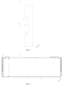
- FIG. 1 is a top view of a secondary battery provided by the present application in a specific embodiment
- FIG. 2 is an exploded diagram of FIG. 1
- FIG. 3 is a schematic structural diagram of an electrode assembly in FIG. 2
- FIG. 4 is a schematic structural diagram showing a connection between a connecting component and a flow guiding component in FIG. 2
- FIG. 5 is a schematic structural diagram of the flow guiding component in FIG. 4
- FIG. 6 is a sectional view taken along a line A-A of FIG. 1
- FIG. 7 is a partial enlarged diagram of part I in FIG. 6
- FIG. 8 is a schematic diagram of a cathodic plate, an anodic plate and a separator in FIG. 3
- FIG. 9 is a sectional view taken along a line B-B of FIG. 8 .
- the secondary battery includes an electrode assembly 1, a cap assembly 4, and a case 6.
- the case 6 may be a hexahedral shape or other shapes, and the case 6 forms an accommodating cavity configured to accommodate the electrode assembly 1 and an electrolyte.
- One end of the case 6 is provided with an opening so that the electrode assembly 1 could be placed into the accommodating cavity of the case 6 through the opening.
- the case 6 may include a metal material, such as aluminum or aluminum alloy, and may also include an insulating material, such as plastic.
- the electrode assembly 1 includes an electrode unit 11 and tabs 12.
- the electrode unit 11 includes two side portions 114 disposed oppositely along a length direction X.
- the two tabs 12 extend from the two side portions 114 of the electrode unit 11, respectively.
- the electrode unit 11 includes an anodic plate 111, a cathodic plate 112, and a separator 113, where the separator 113 is located between the adjacent anodic plate 111 and the cathodic plate 112 to space the anodic plate 111 from the cathodic plate 112.
- the anodic plate 111, the separator 113, and the cathodic plate 112 are sequentially stacked and wound to form the electrode unit 11 of the electrode assembly 1. That is, the electrode unit 11 has a winding structure.
- the anodic plate 111, the separator 113, and the cathodic plate 112 are sequentially stacked to form the electrode unit 11 of the electrode assembly 1, and the electrode unit 11 has a laminated structure. At the same time, there are gaps after the electrode unit 11 is formed, and the electrolyte could enter the electrode unit 11 through the gaps to infiltrate the anodic plate 111 and the cathodic plate 112.
- the anodic plate 111 includes an anode current collector (e.g., copper foil) and an anode active material layer (e.g., graphite, carbon or silicon) coated on a surface of the anode current collector.
- the cathodic plate 112 includes a cathode current collector (e.g., aluminum foil) and a cathode active material layer (e.g., a ternary material, lithium iron phosphate, or lithium cobaltate) coated on a surface of the cathode current collector.
- the tab 12 is connected to the anodic plate 111 and extends from the electrode unit 11, and the tab 12 may be directly formed from the anode current collector by cutting.
- the tab 12 is connected to the cathodic plate 112 and extends from the electrode unit 11, and the tab 12 may be directly formed from the cathode current collector by cutting.
- the cap assembly 4 includes a cap plate 41 and electrode terminals 42, the cap plate 41 is fixed to the opening of the case 6, thereby sealing the electrode assembly 1 and the electrolyte in the accommodating cavity of the case 6.
- the electrode terminals are arranged on the cap plate 41 and include an anode electrode terminal and a cathode electrode terminal.
- the anode electrode terminal and the cathode electrode terminal are respectively electrically connected to a corresponding tab 12 through a connecting component 3, and the cap plate 41 is provided with an explosion-proof opening 411.
- the secondary battery further includes a flow guiding component 2 located in the accommodating cavity of the case 6.
- the flow guiding component 2 can absorb the electrolyte and includes an anode flow guiding component 21 and a cathode flow guiding component 22. At least part of the flow guiding component 2 is in contact with a corresponding side portion 114, and the two flow guiding components 2 are in contact with the electrolyte.
- the two flow guiding components 2 of the secondary battery have a split structure, and there is no connecting part between the two.
- the flow guiding component 2 is provided with an avoiding portion 23, and the avoiding portion 23 is configured to avoid the tab 12.
- part of the electrolyte injected into the accommodating cavity of the case 6 could be absorbed by the flow guiding component 2, and the electrolyte could diffuse in the flow guiding component 2. Since the flow guiding component 2 is in contact with the electrode unit 11 of the electrode assembly 1, the electrolyte in the flow guiding component 2 which is in contact with the electrode unit 11 enters the electrode unit 11 as the electrolyte in the electrode unit 11 is consumed, and thus the electrolyte in the accommodating cavity is continuously passed into the electrode unit 11, the electrolyte wettability in the electrode assembly 1 is improved, the risk of lithium precipitation for the electrode assembly 1 is reduced, and the service life of the secondary battery is increased.
- the electrode assembly 1 and the case 6 could compress the flow guiding component 2, so that the flow guiding component 2 could release the electrolyte stored therein, the liquid retention capacity of the secondary battery is improved, and the service life of secondary battery is further improved.
- the tab 12 could be avoided, that is, the tab 12 could extend through the avoiding portion 23, so as to realize fixed connection between the tab 12 and the connecting component 3.
- the connection between the tab 12 and the connecting component 3 is a welded connection
- the arrangement of the avoiding portion 23 could also reduce a risk of damaging the flow guiding component 2 by heat during a welding process, and improve the service life of the flow guiding component 2 and the secondary battery.
- the connecting component 3 includes a first connecting portion 31 and a second connecting portion 32, where the first connecting portion 31 extends to a top of the electrode assembly 1 for connecting to the cap assembly 4.
- the second connecting portion 32 extends to a side portion of the electrode assembly 1 for connecting to the tab 12.
- the tab 12 includes a body portion 121 and an extension portion 122, where the body portion 121 extends from the side portion 114 of the electrode unit 11, and the extension portion 122 extends from the electrode unit 11 and then bends, that is, the extension portion 122 is bent relative to the body portion 121, where the body portion 121 and the cap assembly 4 are connected by the connecting component 3. At the same time, at least part of the body portion 121 is located in the avoiding portion 23.
- the body portion 121 is attached to the side portion 114, and there is a gap between the extension portion 122 and the body portion 121 along the length direction X. Therefore, when the flow guiding component 2 abuts against the side portion 114, there is a risk of interference between the flow guiding component 2 and the body portion 121 of the tab 12.
- the body portion 121 could be avoided, so that the flow guiding component 2 could be attached to the side portion 114 without being affected by the body portion 121, and thus the wettability of the flow guiding component 2 is improved by the electrode assembly 1, and at the same time, the flow guiding component 2 does not interfere with the body portion 121, a size of the secondary battery in a length direction could be reduced, and energy density of the secondary battery could be increased.
- the secondary battery is formed, at least part of the body portion 121 is located in the avoiding portion 23.
- the avoiding portion 23 includes a recess provided on the flow guiding component 2.
- the recess includes a first side wall 231 and a second side wall 232 disposed oppositely, and at least part of the body portion 121 is located in the recess. And along the height direction Z, the first side wall 231 and the second side wall 232 abut against the body portion 121, respectively.
- the position of the flow guiding component 2 could be restricted along the height direction Z by the body portion 121 of the tab 12, thereby preventing the flow guiding component 2 from moving along the height direction Z relative to the tab 12, and improving stability of the flow guiding component 2 in the secondary battery.
- the recess includes a third side wall 233 along a width direction Y, and the third side wall 233 abuts against the body portion 121.
- the position of the flow guiding component 2 could be restricted along the width direction Y by the body portion 121 of the tab 12, thereby preventing the flow guiding component 2 from moving along the width direction Y relative to the tab 12, and further improving the stability of flow guiding component 2 in the secondary battery.
- the body portion 121 may extend beyond the recess along a side far away from the third side wall 233, or the body portion may also be all located in the recess. Therefore, at least part of the body portion 121 is located in the recess.
- the flow guiding component 2 has a plate-shaped structure, and along the width direction Y, one end surface of the flow guiding component 2 is attached to the side portion 114 of the electrode unit 11, and the other end surface is fixedly connected to the connecting component 3.
- contact area between the flow guiding component 2 of the plate-shaped structure and the side portion 114 is relatively large, so that a capability of the flow guiding component 2 to transport the electrolyte into the electrode assembly 1 could be improved, thereby further improving the service life of the secondary battery.
- the flow guiding component 2 could be fixed in the case 6, where the flow guiding component 2 and the connecting component 3 may be connected by gluing.
- a width of the flow guiding component 2 is smaller than a width of the connecting component 3, and at the same time, the width of the flow guiding component 2 is also smaller than a width of the corresponding side portion 114.
- the width of the flow guiding component 2 could not exceed the width of the connecting component 3. In this embodiment, the width of the flow guiding component 2 needs be as large as possible to increase the contact area between the flow guiding component 2 and the side portion 114 but avoid occupying too much space.
- a height of the flow guiding component 2 is greater than or equal to a height of the electrode assembly 1, so as to ensure that the electrolyte at the bottom of the case 6 could be transported to the electrode assembly 1 through the flow guiding component 2, and when the height of the flow guiding component 2 is equal to the height of the electrode assembly 1, the volume of the flow guiding component 2 could be reduced and the energy density of the secondary battery could be increased while the flow guiding component 2 is ensured to have a high capability to transport the electrolyte.
- the first connecting portion 31 and the second connecting portion 32 of the connecting component 3 are bent relative to each other.
- the first connecting portion 31 is configured to connect to the cap assembly 4, and the second connecting portion 32 is configured to connect to the tab 12 Therefore, the first connecting portion 31 and the second connecting portion 32 are bent at the top of the electrode assembly 1. Therefore, along the height direction Z, one end (upper end) of the flow guiding component 2 extends to a position where the first connecting portion 31 and the second connecting portion 32 are bent relative to each other, and the other end (lower end) abuts against the bottom of the case 6.
- the insulating membrane 5 is located in the inner cavity of the case 6; and, along the height direction Z, the upper end of the flow guiding component 2 extends to the position where the first connecting portion 31 and the second connecting portion 32 are bent relative to each other, and the lower end abuts against the bottom of the insulating membrane 5.
- the electrode unit 11 includes a plurality of anodic plates 111, a plurality of cathodic plates 112, and a plurality of separators 113.
- the separator 113 is located between adjacent anodic plate 111 and cathodic plate 112.
- the separator 113 is used to isolate the anodic plate 111 from the cathodic plate 112.
- a size of the separator 113 is larger than a size of the anodic plate 111 and a size of the cathodic plate 112. As shown in FIG.
- the separator 113 has first end portions 113a extending beyond the anodic plate 111 and the cathodic plate 112, and a thickness of the flow guiding component 2 is greater than or equal to a distance between the first end portion 113a and the connecting component 3.
- the first end portions 113a of the separator 113 extend beyond the anodic plate 111 and the cathodic plate 112, for the electrode unit 11, the first end portions 113a of the separator 113 are the most outer end along the width direction Y, and therefore, when the flow guiding component 2 is connected to the connecting component 3 and abuts against the electrode assembly 1, the flow guiding component 2 first contacts the first end portion 113a.
- the thickness of the flow guiding component 2 is too small (less than the distance between the connecting component 3 and the first end portion 113a), the flow guiding component 2 cannot abut against the electrode assembly 1, or cannot be fixedly connected to the connecting component portion 3. Therefore, in order to achieve fixing the flow guiding component 2 in the secondary battery and transporting the electrolyte to the electrode unit 11, the thickness of the flow guiding component 2 is greater than or equal to the distance between the first end portion 113 a and the connecting component 3.
- the electrode unit 11 includes a cathode and an anode
- the flow guiding component 2 includes an anode flow guiding component 21 and a cathode flow guiding component 22, and the anode flow guiding component 21 is located on the anode side of the electrode unit 11, while the cathode flow guiding component 22 is located on the cathode side of the electrode unit 11.
- the cathodic plate 112 On the cathode side of the electrode unit 11, the cathodic plate 112 includes a third end portion 112a extending beyond the anodic plate 111, and along the width direction Y, the third end portion 112a portion is located between the first end portion 113a and the anodic plate 111, that is, the third end portion 112a extends beyond the anodic plate 111, but does not extend beyond the first end portion 113a of the separator 113.
- a first thickness D 1 of the cathode flow guiding component 22 satisfies D 1 ⁇ d 1 + d 2 , where d 1 is the distance between the first end portion 113a and the connecting component 3, and d 2 is a distance between the first end portion 113a and the third end portion 112a. That is, the first thickness of the cathode flow guiding component 22 satisfies: d 1 ⁇ D 1 ⁇ d 1 + d 2 .
- the cathode flow guiding component 22 when the first thickness D 1 of the cathode flow guiding component 22 is smaller than d 1 , the cathode flow guiding component 22 cannot contact with the electrode unit 11, and when the first thickness D 1 of the cathode flow guiding component 22 is greater than d 1 , the cathode flow guiding component 22 contacts with the electrode unit 11 and then squeezes the separator 113, and when the first thickness D 1 of the cathode flow guiding component is too large ( D 1 > d 1 + d 2 ), the cathode flow guiding component 22 not only squeezes the separator 113, but also squeezes the third end portion 112a of the cathodic plate 112, causing that the cathodic plate 112 is bent inward (toward a center of the electrode assembly 1 ), which leads to that the cathodic plate 112 contacts with the anodic plate 111, thereby causing the cathode and anode of the electrode unit 11 to be short-circuited.
- the anode plate 111 includes a second end portion 111a extending beyond the cathodic plate 112, and along the width direction Y, the second end portion 111a is located between the cathodic plate 112 and the first end portion 113a, that is, the first end 113a extends beyond the cathodic plate 112, but does not extend beyond the first end portion 113a of the separator 113.
- a second thickness D 2 of the anode flow guiding component 21 satisfies D 2 ⁇ d 1 + d 3 , where d 1 is the distance between the first end portion 113a and the connecting component 3, and d 3 is a distance between the first end portion 113a and the second end portion 111a.
- the cathode flow guiding component 21 Similar to the cathode flow guiding component 22, when the second thickness of the anode flow guiding component 21 satisfies d 1 ⁇ D 2 ⁇ d 1 + d 2 , the anodic plate 111 on the anode side and the cathodic plate 112 could be prevented from being short-circuited, and it could be ensured that the anode flow guiding component 21 abuts against the anode side of the electrode unit 11.
- the second thickness D 2 of the anode flow guiding component 21 and the first thickness D 1 of the cathode flow guiding component 22 may be the same or different, and specific values of D 1 and D 2 can be determined according to parameters of the anode side and the cathode side of the electrode unit.
- L 1 is a total length of the anodic plates 111, or a total length of the cathodic plates 112
- the total length of the anodic plates 111 refers to the total length of the anodic plates 111 after the electrode assembly 1 is spread, that is, a sum of the lengths of the anodic plates 111
- W 1 is a width of an active material layer on the anodic plates 111 or a width of an active material layer on the cathodic plates 112, as shown in FIG.
- G is a distance between adjacent anodic plates 111, or a distance between adjacent cathodic plates 112;
- L 2 is a total length of the separators 113, which represent, the total length of the separators 113 after the electrode assembly 1 is spread, that is a sum of the lengths of the separators 113;
- W 2 is a width of the separators 113, as shown in FIG. 8 ;
- H 3 is a height of the electrode assembly 1, as shown in FIG. 6 ;
- W 3 is a width of the connecting component 3, as shown in FIG. 4 ;
- ⁇ 1 is a liquid retention coefficient of the separators 113;
- ⁇ 2 is a liquid retention coefficient of the flow guiding component 2.
- each parameter in formula (1) is a measurable parameter or a known parameter, and the thickness d of the flow guiding component 2 can be calculated by this formula.
- Embodiments of the present application also provide a battery pack, including a secondary battery described in a foregoing embodiment.
- Embodiments of the present application also provide an electric device, including a secondary battery described in a foregoing embodiment, where the secondary battery is used to provide electrical energy, and the device may be a vehicle or an energy storage device.
Landscapes
- Chemical & Material Sciences (AREA)
- Chemical Kinetics & Catalysis (AREA)
- Electrochemistry (AREA)
- General Chemical & Material Sciences (AREA)
- Engineering & Computer Science (AREA)
- Manufacturing & Machinery (AREA)
- Secondary Cells (AREA)
- Connection Of Batteries Or Terminals (AREA)
Claims (12)
- Sekundärbatterie, wobei die Sekundärbatterie umfasst:ein Gehäuse (6), das eine Öffnung und einen inneren Hohlraum umfasst,wobei ein Elektrolyt in dem inneren Hohlraum umfasst ist;eine Kappenanordnung (4), welche die Öffnung abdeckt;eine Elektrodenanordnung (1), die in dem inneren Hohlraum angeordnet ist und eine Elektrodeneinheit (11) und Laschen (12) umfasst; wobei entlang einer Längsrichtung die Elektrodeneinheit (11) zwei gegenüberliegend angeordnete Seitenabschnitte (114) umfasst und sich die Laschen (12) von den Seitenabschnitten (114) aus erstrecken, wobei die Längsrichtung senkrecht zu einer Abdeckungsrichtung ist, in der die Kappenanordnung (4) die Öffnung des Gehäuses (6) abdeckt;Verbindungskomponenten (3), die so konfiguriert sind, dass sie die Laschen (12) und die Kappenanordnung (4) miteinander verbinden; undeine Strömungsführungskomponente, die zwischen einer entsprechenden Verbindungskomponente und einem entsprechenden Seitenabschnitt angeordnet und mit der Verbindungskomponente (3) verbunden ist, wobei mindestens ein Teil der Strömungsführungskomponente (2) in Kontakt mit dem entsprechenden Seitenabschnitt (114) steht und die Strömungsführungskomponente (2) in Kontakt mit dem Elektrolyt steht und die Strömungsführungskomponente (2) den Elektrolyt absorbiert;wobei die Strömungsführungskomponente (2) mit einem Ausweichabschnitt (23) versehen ist, der so konfiguriert ist, dass er die Laschen (12) vermeidet.
- Sekundärbatterie nach Anspruch 1, wobei:
jede der Laschen (12) einen Körperabschnitt (121) und einen Verlängerungsabschnitt (122) umfasst, wobei sich der Körperabschnitt (121) von dem entsprechenden Seitenabschnitt (114) aus erstreckt und der Verlängerungsabschnitt (122) relativ zu dem Körperabschnitt (121) gebogen ist; und mindestens ein Teil des Körperabschnitts (121) in dem Ausweichabschnitt (23) angeordnet ist. - Sekundärbatterie nach Anspruch 1 oder 2, wobei:die Strömungsführungskomponente (2) eine plattenförmige Struktur ist; undentlang einer Breitenrichtung ein Ende der Strömungsführungskomponente (2) fest mit der Verbindungskomponente (3) verbunden ist und das andere Ende an dem Seitenabschnitt (114) angebracht ist, wobei die Breitenrichtung senkrecht zu der Längsrichtung und einer Höhenrichtung ist und die Höhenrichtung entgegengesetzt zu der Abdeckungsrichtung ist.
- Sekundärbatterie nach einem der Ansprüche 1 bis 3, wobei:
entlang einer Breitenrichtung eine Breite der Strömungsführungskomponente (2) kleiner ist als eine Breite der Verbindungskomponenten (3). - Sekundärbatterie nach einem der Ansprüche 1 bis 4, wobei:entlang einer Höhenrichtung eine Höhe der Strömungsführungskomponente (2) größer oder gleich einer Höhe der Elektrodenanordnung (1) ist;jede der Verbindungskomponenten (3) einen ersten Verbindungsabschnitt (31) und einen zweiten Verbindungsabschnitt (32) umfasst, wobei der erste Verbindungsabschnitt (31) so konfiguriert ist, dass er mit der Kappenanordnung (4) verbunden wird, der zweite Verbindungsabschnitt (32) so konfiguriert ist, dass er mit einer Lasche (12) verbunden wird, und der erste Verbindungsabschnitt (31) relativ zum zweiten Verbindungsabschnitt (32) gebogen ist;sich entlang einer Höhenrichtung ein Ende der Strömungsführungskomponente (2) in eine Position erstreckt, in welcher der erste Verbindungsabschnitt (31) und der zweite Verbindungsabschnitt (32) relativ zueinander gebogen sind, und das andere Ende der Strömungsführungskomponente (2) an einem Boden des Gehäuses anliegt; oder,die Sekundärbatterie ferner eine isolierende Membran umfasst, die zwischen dem Gehäuse und der Elektrodenanordnung (1) angeordnet ist, und sich entlang einer Höhenrichtung ein Ende der Strömungsführungskomponente (2) in eine Position erstreckt, in welcher der erste Verbindungsabschnitt und der zweite Verbindungsabschnitt (32) relativ zueinander gebogen sind, und das andere Ende der Strömungsführungskomponente (2) an einem Boden der isolierenden Membran anliegt.
- Sekundärbatterie nach einem der Ansprüche 1 bis 5, wobei:die Elektrodenanordnung (1) eine Vielzahl von anodischen Platten (111), eine Vielzahl von kathodischen Platten (112) und eine Vielzahl von Separatoren (113) umfasst, und die Separatoren (113) zwischen den anodischen Platten (111) und den kathodischen Platten (112), die benachbart sind, angeordnet sind;entlang einer Breitenrichtung jeder der Separatoren (113) erste Endabschnitte (113a) umfasst, die sich über die anodischen Platten (111) und die kathodischen Platten (112) hinaus erstrecken; undeine Dicke der Strömungsführungskomponente (2) größer oder gleich einer Entfernung zwischen dem ersten Endabschnitt (113) und der Verbindungskomponente (3) ist.
- Sekundärbatterie nach Anspruch 6, wobei:die Strömungsführungskomponente (2) eine Anodenströmungsführungskomponente (21) und eine Kathodenströmungsführungskomponente (22) umfasst, wobei die Anodenströmungsführungskomponente (21) und die Kathodenströmungsführungskomponente (22) jeweils auf zwei Seiten der Elektrodenanordnung (1) entlang der Breitenrichtung angeordnet sind;an einer Kathode der Elektrodenanordnung (1) jede der kathodischen Platten (112) einen dritten Endabschnitt (112a) umfasst, der sich über die anodischen Platten (111) hinaus erstreckt, und entlang der Breitenrichtung der dritte Endabschnitt (112a) zwischen einem ersten Endabschnitt (113) und den anodischen Platten (111) angeordnet ist;eine erste Dicke D 1 der Kathodenströmungsführungskomponente (22) D 1 ≤ d 1 + d 2 erfüllt;wobei d 1 eine Entfernung zwischen dem ersten Endabschnitt (113) und der Verbindungskomponente (3) ist, und d 2 eine Entfernung zwischen dem ersten Endabschnitt (113) und dem dritten Endabschnitt (112a) ist.
- Sekundärbatterie nach Anspruch 6 oder 7, wobei:die Strömungsführungskomponente (2) eine Anodenströmungsführungskomponente (21) und eine Kathodenströmungsführungskomponente (22) umfasst, wobei die Anodenströmungsführungskomponente (21) und die Kathodenströmungsführungskomponente (22) jeweils auf zwei Seiten der Elektrodenanordnung (1) entlang der Breitenrichtung angeordnet sind;an einer Anode der Elektrodenanordnung (1) jede der anodischen Platten (111) einen zweiten Endabschnitt (111a) umfasst, der sich über die kathodischen Platten (112) hinaus erstreckt, und entlang der Breitenrichtung der zweite Endabschnitt (111a) zwischen den kathodischen Platten (112) und dem ersten Endabschnitt (113) angeordnet ist;eine zweite Dicke D 2 der Anodenströmungsführungskomponente (21) D 2 ≤ d 1 + d 3 erfüllt;wobei d 1 eine Entfernung zwischen dem ersten Endabschnitt (113) und der Verbindungskomponente (3) ist, und d 3 eine Entfernung zwischen dem ersten Endabschnitt (113) und dem zweiten Endabschnitt (111a) ist.
- Sekundärbatterie nach einem der Ansprüche 6 bis 8, wobei:eine Dicke d der Strömungsführungskomponente (2) eine folgende Formel erfüllt:
 wobei L 1 eine Gesamtlänge der anodischen Platten (111) oder eine Gesamtlänge der kathodischen Platten (112) ist; W 1 eine Breite einer aktiven Materialschicht der anodischen Platten (111) oder eine Breite einer aktiven Materialschicht der kathodischen Platten (112) ist;G eine Entfernung zwischen den anodischen Platten (111), die benachbart sind, oder eine Entfernung zwischen den kathodischen Platten (112), die benachbart sind, ist;L 2 eine Gesamtlänge der Separatoren (113) ist; W 2 eine Breite der Separatoren (113) ist;H 3 eine Höhe der Elektrodenanordnung (1) ist; W 3 eine Breite der Verbindungskomponenten (3) ist;ρ 1 ein Flüssigkeitsrückhaltekoeffizient der Separatoren (113) ist; ρ 2 ein Flüssigkeitsrückhaltekoeffizient der Strömungsführungskomponente (2) ist.
 - Sekundärbatterie nach einem der Ansprüche 2 bis 9, wobei:der Ausweichabschnitt (23) eine Aussparung ist;entlang einer Höhenrichtung die Aussparung eine erste Seitenwand (231) und eine zweite Seitenwand (232) umfasst, die gegenüberliegend angeordnet sind, und die erste Seitenwand und die zweite Seitenwand jeweils an dem Körperabschnitt (121) anliegen; undentlang einer Breitenrichtung die Aussparung eine dritte Seitenwand (233) umfasst und die dritte Seitenwand (233) an dem Körperabschnitt (121) anliegt.
- Batteriesatz, umfassend: eine Sekundärbatterie nach einem der Ansprüche 1 bis 10.
- Elektrische Vorrichtung, umfassend: eine Sekundärbatterie nach einem der Ansprüche 1 bis 10, wobei die Sekundärbatterie zur Bereitstellung elektrischer Energie verwendet wird.
Applications Claiming Priority (2)
| Application Number | Priority Date | Filing Date | Title |
|---|---|---|---|
| CN201920735006.1U CN209675429U (zh) | 2019-05-21 | 2019-05-21 | 一种二次电池 |
| PCT/CN2020/085486 WO2020233302A1 (zh) | 2019-05-21 | 2020-04-19 | 一种二次电池、电池组及用电装置 |
Publications (4)
| Publication Number | Publication Date |
|---|---|
| EP3799182A1 EP3799182A1 (de) | 2021-03-31 |
| EP3799182A4 EP3799182A4 (de) | 2021-09-08 |
| EP3799182C0 EP3799182C0 (de) | 2025-01-22 |
| EP3799182B1 true EP3799182B1 (de) | 2025-01-22 |
Family
ID=68575310
Family Applications (1)
| Application Number | Title | Priority Date | Filing Date |
|---|---|---|---|
| EP20809286.6A Active EP3799182B1 (de) | 2019-05-21 | 2020-04-19 | Sekundärbatterie, batteriesatz und elektrische vorrichtung |
Country Status (6)
| Country | Link |
|---|---|
| US (1) | US12155094B2 (de) |
| EP (1) | EP3799182B1 (de) |
| CN (1) | CN209675429U (de) |
| ES (1) | ES3024483T3 (de) |
| HU (1) | HUE070999T2 (de) |
| WO (1) | WO2020233302A1 (de) |
Families Citing this family (6)
| Publication number | Priority date | Publication date | Assignee | Title |
|---|---|---|---|---|
| CN209675429U (zh) | 2019-05-21 | 2019-11-22 | 宁德时代新能源科技股份有限公司 | 一种二次电池 |
| CN212277344U (zh) * | 2020-06-28 | 2021-01-01 | 比亚迪股份有限公司 | 电芯引出片、电池及电动汽车 |
| HUE067564T2 (hu) * | 2021-02-09 | 2024-10-28 | Contemporary Amperex Technology Hong Kong Ltd | Elektródaszerelvény és ahhoz tartozó akkumulátor, berendezés, elõállítási eljárás és elõállító-berendezés |
| CN114142181A (zh) * | 2021-11-30 | 2022-03-04 | 蜂巢能源科技有限公司 | 电芯、电芯装配方法及电池 |
| EP4435953A4 (de) * | 2022-03-18 | 2025-09-03 | Contemporary Amperex Technology Hong Kong Ltd | Batteriezelle und herstellungsverfahren und herstellungssystem dafür, batterie und elektrische vorrichtung |
| CN117096514B (zh) * | 2023-10-20 | 2024-03-29 | 江苏时代新能源科技有限公司 | 顶盖组件、电池及用电设备 |
Family Cites Families (11)
| Publication number | Priority date | Publication date | Assignee | Title |
|---|---|---|---|---|
| KR20110037943A (ko) * | 2008-07-02 | 2011-04-13 | 가부시키가이샤 지에스 유아사 코포레이션 | 전지 및 그 제조 방법 |
| KR101147171B1 (ko) * | 2009-04-21 | 2012-05-25 | 에스비리모티브 주식회사 | 이차 전지 |
| WO2012023392A1 (ja) * | 2010-08-19 | 2012-02-23 | 株式会社Gsユアサ | 集電部材を備える蓄電素子及び集電部材の製造方法 |
| CN102683735B (zh) * | 2011-03-16 | 2017-03-01 | 株式会社杰士汤浅国际 | 蓄电元件 |
| US8748034B2 (en) * | 2011-04-14 | 2014-06-10 | Gs Yuasa International Ltd. | Battery including baffling member including one of projecting portion and recessed portion extending from lid plate |
| US9005793B2 (en) * | 2012-05-23 | 2015-04-14 | General Electric Company | Energy storage article and method |
| JP2017059509A (ja) * | 2015-09-18 | 2017-03-23 | リチウム エナジー アンド パワー ゲゼルシャフト ミット ベシュレンクテル ハフッング ウント コンパニー コマンディトゲゼルシャフトLithium Energy and Power GmbH & Co. KG | 蓄電素子 |
| JP2018092814A (ja) * | 2016-12-05 | 2018-06-14 | 株式会社Gsユアサ | 蓄電素子 |
| CN206574809U (zh) * | 2017-02-07 | 2017-10-20 | 山东衡远新能源科技有限公司 | 一种铝壳电芯结构 |
| CN208819970U (zh) * | 2018-10-26 | 2019-05-03 | 宁德时代新能源科技股份有限公司 | 二次电池 |
| CN209675429U (zh) * | 2019-05-21 | 2019-11-22 | 宁德时代新能源科技股份有限公司 | 一种二次电池 |
-
2019
- 2019-05-21 CN CN201920735006.1U patent/CN209675429U/zh active Active
-
2020
- 2020-04-19 EP EP20809286.6A patent/EP3799182B1/de active Active
- 2020-04-19 ES ES20809286T patent/ES3024483T3/es active Active
- 2020-04-19 WO PCT/CN2020/085486 patent/WO2020233302A1/zh not_active Ceased
- 2020-04-19 HU HUE20809286A patent/HUE070999T2/hu unknown
-
2021
- 2021-01-11 US US17/145,613 patent/US12155094B2/en active Active
Also Published As
| Publication number | Publication date |
|---|---|
| EP3799182C0 (de) | 2025-01-22 |
| WO2020233302A1 (zh) | 2020-11-26 |
| HUE070999T2 (hu) | 2025-07-28 |
| US12155094B2 (en) | 2024-11-26 |
| EP3799182A4 (de) | 2021-09-08 |
| US20210135325A1 (en) | 2021-05-06 |
| CN209675429U (zh) | 2019-11-22 |
| ES3024483T3 (en) | 2025-06-04 |
| EP3799182A1 (de) | 2021-03-31 |
Similar Documents
| Publication | Publication Date | Title |
|---|---|---|
| EP3799182B1 (de) | Sekundärbatterie, batteriesatz und elektrische vorrichtung | |
| EP2002495B1 (de) | Lithiumsekundärbatterie mit erhöhter sicherheit und kapazität | |
| KR101233573B1 (ko) | 이차 전지 | |
| EP1901365B1 (de) | Batteriezelle mit schmaler Nut auf der Oberfläche und Batteriesatz damit | |
| EP2388847B1 (de) | Sekundärbatterie mit ersten und zweiten Stromsammelplatten, die ineinander verstrickt sind | |
| KR101147207B1 (ko) | 전극군과 이를 적용한 이차 전지 | |
| EP2515362B1 (de) | Sekundärbatterie | |
| KR101222369B1 (ko) | 배터리 및 이를 포함한 배터리 팩 | |
| EP3890085A1 (de) | Batteriezellenanordnung, batteriemodul und batteriepack | |
| CN216120651U (zh) | 一种电池的电芯及电池 | |
| KR20130132231A (ko) | 단차를 갖는 전극 조립체 및 이를 포함하는 전지셀, 전지팩 및 디바이스 | |
| US12224405B2 (en) | Electrode assembly, secondary battery, and battery-powered apparatus | |
| EP3852166A1 (de) | Stromabnehmerelement, sekundärbatterie und herstellungsverfahren | |
| US8785037B2 (en) | Secondary battery with stepped cap plate | |
| US20220200110A1 (en) | Secondary battery | |
| KR101233514B1 (ko) | 이차 전지 | |
| US11387495B2 (en) | Non-aqueous electrolyte secondary battery | |
| CN209401731U (zh) | 二次电池 | |
| EP2477257B1 (de) | Sekundärbatterie | |
| US20240380074A1 (en) | Battery and electronic device including the same | |
| KR101118700B1 (ko) | 이차전지 | |
| US12469904B2 (en) | Flat secondary battery | |
| KR20180130800A (ko) | 이차 전지 | |
| KR20150000672A (ko) | 만입형 그루브가 형성되어 있는 전지 케이스를 포함하는 전지셀 | |
| EP4664598A1 (de) | Sekundärbatterie |
Legal Events
| Date | Code | Title | Description |
|---|---|---|---|
| STAA | Information on the status of an ep patent application or granted ep patent |
Free format text: STATUS: THE INTERNATIONAL PUBLICATION HAS BEEN MADE |
|
| PUAI | Public reference made under article 153(3) epc to a published international application that has entered the european phase |
Free format text: ORIGINAL CODE: 0009012 |
|
| STAA | Information on the status of an ep patent application or granted ep patent |
Free format text: STATUS: REQUEST FOR EXAMINATION WAS MADE |
|
| 17P | Request for examination filed |
Effective date: 20201222 |
|
| AK | Designated contracting states |
Kind code of ref document: A1 Designated state(s): AL AT BE BG CH CY CZ DE DK EE ES FI FR GB GR HR HU IE IS IT LI LT LU LV MC MK MT NL NO PL PT RO RS SE SI SK SM TR |
|
| AX | Request for extension of the european patent |
Extension state: BA ME |
|
| A4 | Supplementary search report drawn up and despatched |
Effective date: 20210805 |
|
| RIC1 | Information provided on ipc code assigned before grant |
Ipc: H01M 50/531 20210101ALI20210730BHEP Ipc: H01M 10/058 20100101ALI20210730BHEP Ipc: H01M 10/052 20100101AFI20210730BHEP |
|
| DAV | Request for validation of the european patent (deleted) | ||
| DAX | Request for extension of the european patent (deleted) | ||
| REG | Reference to a national code |
Ref legal event code: R079 Ref country code: DE Ref legal event code: R079 Ref document number: 602020045237 Country of ref document: DE Free format text: PREVIOUS MAIN CLASS: H01M0010052000 Ipc: H01M0010040000 |
|
| RIC1 | Information provided on ipc code assigned before grant |
Ipc: H01M 10/052 20100101ALI20240726BHEP Ipc: H01M 50/70 20210101ALI20240726BHEP Ipc: H01M 50/533 20210101ALI20240726BHEP Ipc: H01M 50/103 20210101ALI20240726BHEP Ipc: H01M 10/0587 20100101ALI20240726BHEP Ipc: H01M 10/04 20060101AFI20240726BHEP |
|
| GRAP | Despatch of communication of intention to grant a patent |
Free format text: ORIGINAL CODE: EPIDOSNIGR1 |
|
| STAA | Information on the status of an ep patent application or granted ep patent |
Free format text: STATUS: GRANT OF PATENT IS INTENDED |
|
| RAP1 | Party data changed (applicant data changed or rights of an application transferred) |
Owner name: CONTEMPORARY AMPEREX TECHNOLOGY(HONG KONG) LIMITED |
|
| INTG | Intention to grant announced |
Effective date: 20240923 |
|
| GRAS | Grant fee paid |
Free format text: ORIGINAL CODE: EPIDOSNIGR3 |
|
| GRAA | (expected) grant |
Free format text: ORIGINAL CODE: 0009210 |
|
| STAA | Information on the status of an ep patent application or granted ep patent |
Free format text: STATUS: THE PATENT HAS BEEN GRANTED |
|
| AK | Designated contracting states |
Kind code of ref document: B1 Designated state(s): AL AT BE BG CH CY CZ DE DK EE ES FI FR GB GR HR HU IE IS IT LI LT LU LV MC MK MT NL NO PL PT RO RS SE SI SK SM TR |
|
| REG | Reference to a national code |
Ref country code: GB Ref legal event code: FG4D |
|
| REG | Reference to a national code |
Ref country code: CH Ref legal event code: EP |
|
| REG | Reference to a national code |
Ref country code: IE Ref legal event code: FG4D |
|
| REG | Reference to a national code |
Ref country code: DE Ref legal event code: R096 Ref document number: 602020045237 Country of ref document: DE |
|
| U01 | Request for unitary effect filed |
Effective date: 20250212 |
|
| U07 | Unitary effect registered |
Designated state(s): AT BE BG DE DK EE FI FR IT LT LU LV MT NL PT RO SE SI Effective date: 20250219 |
|
| U20 | Renewal fee for the european patent with unitary effect paid |
Year of fee payment: 6 Effective date: 20250422 |
|
| REG | Reference to a national code |
Ref country code: ES Ref legal event code: FG2A Ref document number: 3024483 Country of ref document: ES Kind code of ref document: T3 Effective date: 20250604 |
|
| PG25 | Lapsed in a contracting state [announced via postgrant information from national office to epo] |
Ref country code: RS Free format text: LAPSE BECAUSE OF FAILURE TO SUBMIT A TRANSLATION OF THE DESCRIPTION OR TO PAY THE FEE WITHIN THE PRESCRIBED TIME-LIMIT Effective date: 20250422 |
|
| PG25 | Lapsed in a contracting state [announced via postgrant information from national office to epo] |
Ref country code: PL Free format text: LAPSE BECAUSE OF FAILURE TO SUBMIT A TRANSLATION OF THE DESCRIPTION OR TO PAY THE FEE WITHIN THE PRESCRIBED TIME-LIMIT Effective date: 20250122 |
|
| PGFP | Annual fee paid to national office [announced via postgrant information from national office to epo] |
Ref country code: GB Payment date: 20250417 Year of fee payment: 6 Ref country code: ES Payment date: 20250506 Year of fee payment: 6 |
|
| PG25 | Lapsed in a contracting state [announced via postgrant information from national office to epo] |
Ref country code: NO Free format text: LAPSE BECAUSE OF FAILURE TO SUBMIT A TRANSLATION OF THE DESCRIPTION OR TO PAY THE FEE WITHIN THE PRESCRIBED TIME-LIMIT Effective date: 20250422 Ref country code: IS Free format text: LAPSE BECAUSE OF FAILURE TO SUBMIT A TRANSLATION OF THE DESCRIPTION OR TO PAY THE FEE WITHIN THE PRESCRIBED TIME-LIMIT Effective date: 20250522 |
|
| PGFP | Annual fee paid to national office [announced via postgrant information from national office to epo] |
Ref country code: HU Payment date: 20250320 Year of fee payment: 6 |
|
| PG25 | Lapsed in a contracting state [announced via postgrant information from national office to epo] |
Ref country code: HR Free format text: LAPSE BECAUSE OF FAILURE TO SUBMIT A TRANSLATION OF THE DESCRIPTION OR TO PAY THE FEE WITHIN THE PRESCRIBED TIME-LIMIT Effective date: 20250122 |
|
| PG25 | Lapsed in a contracting state [announced via postgrant information from national office to epo] |
Ref country code: GR Free format text: LAPSE BECAUSE OF FAILURE TO SUBMIT A TRANSLATION OF THE DESCRIPTION OR TO PAY THE FEE WITHIN THE PRESCRIBED TIME-LIMIT Effective date: 20250423 |
|
| REG | Reference to a national code |
Ref country code: HU Ref legal event code: AG4A Ref document number: E070999 Country of ref document: HU |
|
| PG25 | Lapsed in a contracting state [announced via postgrant information from national office to epo] |
Ref country code: SM Free format text: LAPSE BECAUSE OF FAILURE TO SUBMIT A TRANSLATION OF THE DESCRIPTION OR TO PAY THE FEE WITHIN THE PRESCRIBED TIME-LIMIT Effective date: 20250122 |
|
| PG25 | Lapsed in a contracting state [announced via postgrant information from national office to epo] |
Ref country code: CZ Free format text: LAPSE BECAUSE OF FAILURE TO SUBMIT A TRANSLATION OF THE DESCRIPTION OR TO PAY THE FEE WITHIN THE PRESCRIBED TIME-LIMIT Effective date: 20250122 |
|
| PG25 | Lapsed in a contracting state [announced via postgrant information from national office to epo] |
Ref country code: SK Free format text: LAPSE BECAUSE OF FAILURE TO SUBMIT A TRANSLATION OF THE DESCRIPTION OR TO PAY THE FEE WITHIN THE PRESCRIBED TIME-LIMIT Effective date: 20250122 |
|
| REG | Reference to a national code |
Ref country code: CH Ref legal event code: H13 Free format text: ST27 STATUS EVENT CODE: U-0-0-H10-H13 (AS PROVIDED BY THE NATIONAL OFFICE) Effective date: 20251125 |
|
| PLBE | No opposition filed within time limit |
Free format text: ORIGINAL CODE: 0009261 |
|
| STAA | Information on the status of an ep patent application or granted ep patent |
Free format text: STATUS: NO OPPOSITION FILED WITHIN TIME LIMIT |
|
| PG25 | Lapsed in a contracting state [announced via postgrant information from national office to epo] |
Ref country code: MC Free format text: LAPSE BECAUSE OF FAILURE TO SUBMIT A TRANSLATION OF THE DESCRIPTION OR TO PAY THE FEE WITHIN THE PRESCRIBED TIME-LIMIT Effective date: 20250122 |
|
| 26N | No opposition filed |
Effective date: 20251023 |
|
| PG25 | Lapsed in a contracting state [announced via postgrant information from national office to epo] |
Ref country code: CH Free format text: LAPSE BECAUSE OF NON-PAYMENT OF DUE FEES Effective date: 20250430 |