EP3730004B1 - Porte-pot pour la culture de plantes - Google Patents
Porte-pot pour la culture de plantes Download PDFInfo
- Publication number
- EP3730004B1 EP3730004B1 EP20171160.3A EP20171160A EP3730004B1 EP 3730004 B1 EP3730004 B1 EP 3730004B1 EP 20171160 A EP20171160 A EP 20171160A EP 3730004 B1 EP3730004 B1 EP 3730004B1
- Authority
- EP
- European Patent Office
- Prior art keywords
- wall
- plant
- pot holder
- pot
- holder according
- Prior art date
- Legal status (The legal status is an assumption and is not a legal conclusion. Google has not performed a legal analysis and makes no representation as to the accuracy of the status listed.)
- Active
Links
- XLYOFNOQVPJJNP-UHFFFAOYSA-N water Substances O XLYOFNOQVPJJNP-UHFFFAOYSA-N 0.000 claims description 24
- 125000006850 spacer group Chemical group 0.000 claims description 6
- 239000011248 coating agent Substances 0.000 claims description 5
- 238000000576 coating method Methods 0.000 claims description 5
- 238000005580 one pot reaction Methods 0.000 claims description 4
- 238000003466 welding Methods 0.000 claims description 4
- 229910052782 aluminium Inorganic materials 0.000 claims description 3
- XAGFODPZIPBFFR-UHFFFAOYSA-N aluminium Chemical compound [Al] XAGFODPZIPBFFR-UHFFFAOYSA-N 0.000 claims description 3
- 229910052751 metal Inorganic materials 0.000 claims description 2
- 239000002184 metal Substances 0.000 claims description 2
- 239000003973 paint Substances 0.000 claims description 2
- 239000000843 powder Substances 0.000 claims description 2
- 239000004411 aluminium Substances 0.000 claims 1
- 239000002966 varnish Substances 0.000 claims 1
- 239000000758 substrate Substances 0.000 description 9
- 235000008216 herbs Nutrition 0.000 description 6
- 239000007788 liquid Substances 0.000 description 5
- 239000000463 material Substances 0.000 description 5
- 238000003973 irrigation Methods 0.000 description 3
- 230000002262 irrigation Effects 0.000 description 3
- 238000005192 partition Methods 0.000 description 3
- 239000004033 plastic Substances 0.000 description 3
- 229920003023 plastic Polymers 0.000 description 3
- 230000015572 biosynthetic process Effects 0.000 description 2
- 238000001816 cooling Methods 0.000 description 2
- 238000001704 evaporation Methods 0.000 description 2
- 230000008020 evaporation Effects 0.000 description 2
- 239000003337 fertilizer Substances 0.000 description 2
- 238000009413 insulation Methods 0.000 description 2
- 238000000034 method Methods 0.000 description 2
- 238000012986 modification Methods 0.000 description 2
- 230000004048 modification Effects 0.000 description 2
- 238000001556 precipitation Methods 0.000 description 2
- 210000001015 abdomen Anatomy 0.000 description 1
- 230000003187 abdominal effect Effects 0.000 description 1
- 230000002745 absorbent Effects 0.000 description 1
- 239000002250 absorbent Substances 0.000 description 1
- 230000001154 acute effect Effects 0.000 description 1
- 239000000654 additive Substances 0.000 description 1
- 230000000996 additive effect Effects 0.000 description 1
- 230000000844 anti-bacterial effect Effects 0.000 description 1
- 238000005452 bending Methods 0.000 description 1
- 239000004927 clay Substances 0.000 description 1
- 230000007797 corrosion Effects 0.000 description 1
- 238000005260 corrosion Methods 0.000 description 1
- 230000001419 dependent effect Effects 0.000 description 1
- 238000011161 development Methods 0.000 description 1
- 230000018109 developmental process Effects 0.000 description 1
- 238000001035 drying Methods 0.000 description 1
- 235000013399 edible fruits Nutrition 0.000 description 1
- 230000002349 favourable effect Effects 0.000 description 1
- 235000013305 food Nutrition 0.000 description 1
- 239000008187 granular material Substances 0.000 description 1
- 238000003306 harvesting Methods 0.000 description 1
- 238000007654 immersion Methods 0.000 description 1
- NLYAJNPCOHFWQQ-UHFFFAOYSA-N kaolin Chemical compound O.O.O=[Al]O[Si](=O)O[Si](=O)O[Al]=O NLYAJNPCOHFWQQ-UHFFFAOYSA-N 0.000 description 1
- 238000004519 manufacturing process Methods 0.000 description 1
- 235000015097 nutrients Nutrition 0.000 description 1
- 230000002028 premature Effects 0.000 description 1
- 230000005855 radiation Effects 0.000 description 1
- 239000002689 soil Substances 0.000 description 1
- 239000007921 spray Substances 0.000 description 1
- 239000004575 stone Substances 0.000 description 1
- 238000009423 ventilation Methods 0.000 description 1
Images

Classifications
-
- A—HUMAN NECESSITIES
- A47—FURNITURE; DOMESTIC ARTICLES OR APPLIANCES; COFFEE MILLS; SPICE MILLS; SUCTION CLEANERS IN GENERAL
- A47F—SPECIAL FURNITURE, FITTINGS, OR ACCESSORIES FOR SHOPS, STOREHOUSES, BARS, RESTAURANTS OR THE LIKE; PAYING COUNTERS
- A47F7/00—Show stands, hangers, or shelves, adapted for particular articles or materials
- A47F7/0071—Show stands, hangers, or shelves, adapted for particular articles or materials for perishable goods
- A47F7/0078—Show stands, hangers, or shelves, adapted for particular articles or materials for perishable goods for plants or flowers
-
- A—HUMAN NECESSITIES
- A01—AGRICULTURE; FORESTRY; ANIMAL HUSBANDRY; HUNTING; TRAPPING; FISHING
- A01G—HORTICULTURE; CULTIVATION OF VEGETABLES, FLOWERS, RICE, FRUIT, VINES, HOPS OR SEAWEED; FORESTRY; WATERING
- A01G27/00—Self-acting watering devices, e.g. for flower-pots
- A01G27/02—Self-acting watering devices, e.g. for flower-pots having a water reservoir, the main part thereof being located wholly around or directly beside the growth substrate
-
- A—HUMAN NECESSITIES
- A01—AGRICULTURE; FORESTRY; ANIMAL HUSBANDRY; HUNTING; TRAPPING; FISHING
- A01G—HORTICULTURE; CULTIVATION OF VEGETABLES, FLOWERS, RICE, FRUIT, VINES, HOPS OR SEAWEED; FORESTRY; WATERING
- A01G9/00—Cultivation in receptacles, forcing-frames or greenhouses; Edging for beds, lawn or the like
- A01G9/02—Receptacles, e.g. flower-pots or boxes; Glasses for cultivating flowers
- A01G9/022—Pots for vertical horticulture
- A01G9/025—Containers and elements for greening walls
-
- A—HUMAN NECESSITIES
- A47—FURNITURE; DOMESTIC ARTICLES OR APPLIANCES; COFFEE MILLS; SPICE MILLS; SUCTION CLEANERS IN GENERAL
- A47F—SPECIAL FURNITURE, FITTINGS, OR ACCESSORIES FOR SHOPS, STOREHOUSES, BARS, RESTAURANTS OR THE LIKE; PAYING COUNTERS
- A47F7/00—Show stands, hangers, or shelves, adapted for particular articles or materials
- A47F7/28—Show stands, hangers, or shelves, adapted for particular articles or materials for containers, e.g. flasks, bottles, tins, milk packs
- A47F7/283—Show stands or the like having a compartment for each container
-
- Y—GENERAL TAGGING OF NEW TECHNOLOGICAL DEVELOPMENTS; GENERAL TAGGING OF CROSS-SECTIONAL TECHNOLOGIES SPANNING OVER SEVERAL SECTIONS OF THE IPC; TECHNICAL SUBJECTS COVERED BY FORMER USPC CROSS-REFERENCE ART COLLECTIONS [XRACs] AND DIGESTS
- Y02—TECHNOLOGIES OR APPLICATIONS FOR MITIGATION OR ADAPTATION AGAINST CLIMATE CHANGE
- Y02P—CLIMATE CHANGE MITIGATION TECHNOLOGIES IN THE PRODUCTION OR PROCESSING OF GOODS
- Y02P60/00—Technologies relating to agriculture, livestock or agroalimentary industries
- Y02P60/20—Reduction of greenhouse gas [GHG] emissions in agriculture, e.g. CO2
Definitions
- the present disclosure relates to a plant pot holder for holding one or more plant pots.
- Plants, especially kitchen herbs and smaller ornamental plants, are often commercially available in a plant pot that has a simple design.
- the plant pot often has an essentially cylindrical outer shape and consists of a thin deep-drawn plastic material. In some cases, plant pots with other basic shapes are also available.
- the plant pots usually have a round collar on the upper edge.
- the purchaser will typically remove the plant from the plant pot and transplant it into another vessel of higher quality.
- the buyer can place the plant together with the simple plastic plant pot in a higher-quality and attractive cachepot.
- the cachepot or the higher-quality planter is then usually placed on a flat surface, in the case of kitchen herbs in particular on the kitchen worktop, a window sill or a balcony or terrace table.
- the previously known plant pot holders are not optimally designed.
- a crate is known in which a plurality of plant pots can be used in a grid arrangement.
- the crate has to be parked in a large open area and does not offer an attractive overall aesthetic impression.
- the crate is not suitable for use in the private sector.
- WO 2007/073843 A1 discloses another embodiment of a crate with several troughs for holding plant pots.
- the crate here is formed from a foamed plastics material and has an unpleasing appearance.
- the crate in which a plurality of plant pots are arranged in a grid, for example, has to be placed on a large area.
- cover pots and sleeves for receiving a single plant pot and for producing a more attractive appearance are known, for example from EP 1 790 212 B1 , DE 81 18 605 U1 as EP 2 753 167 B1 .
- a planting device for forming a so-called "green wall” comprises a plurality of planting device units which can be plugged one above the other and which each have a plurality of inclined screens with openings into which plant pots can be inserted.
- Below the planter units is a separate water reservoir provided, in which a pump can be arranged.
- a pump can be arranged below the planter units.
- the water from the water reservoir is pumped up to the planter units via hoses and delivered to the plants via drip lines or spray devices. Excess water drains down within the planter units and is collected centrally in the water reservoir.
- the planter units have a closed box structure.
- CN106069266A discloses a plant pot holder with a reservoir.
- CN102640674A discloses a plant pot holder for drip irrigation.
- the invention solves this problem with the features of the main claim.
- the plant pot holder according to the present disclosure is designed to hold one or preferably several plant pots.
- the plant pot holder has a base body that can be fastened to a substantially vertical object surface in the area of a rear wall.
- the base body therefore does not need to be placed on a flat or horizontal surface. Rather, it is possible to attach it, for example, to a free wall surface in the kitchen, or, for example, to a parapet or railing on the balcony, or to a side wall of a building or a piece of furniture.
- the plant pot holder is designed and intended to be attached to an external window sill.
- a customer can place the plant pot holder in particular on the outside of his kitchen window. Herbs or other kitchen plants can then be used in the plant pot holder together with the purchased plant pot and are therefore always directly accessible.
- the base body has a uniform cross-sectional shape with a wall pointing upwards in the intended fastening position (hereinafter referred to as the upper wall), a wall pointing downwards in the fastening position (hereinafter referred to as the lower wall) and a front intermediate wall (hereinafter referred to as the front wall).
- the front wall extends between the top wall and the bottom wall.
- the top wall and the bottom wall may each have a front end, preferably with the front wall extending between those ends.
- the top wall, front wall and bottom wall are connected to one another in one piece.
- the top wall slopes downward toward the front.
- One, two or more openings are provided in the inclined top wall, each of which forms a pot receptacle for a plant pot.
- a pot holder for holding two or more plant pots, in particular for a group of plant pots, can be provided.
- the inclined arrangement of the top wall in the fastening position has several advantages.
- the top of the plant pot is tilted towards the front, i.e. towards the customer / user, so that the plant is more visible and therefore presented in a more aesthetically pleasing way.
- accessibility to the plant is improved, which is particularly helpful for quickly harvesting leaves, stems, flowers, roots or other plant parts.
- the bottom wall is also inclined downwards towards the front.
- end walls are arranged at the end ends of the main body (ie, at the outer ends in the longitudinal direction) between the inclined bottom wall and the front wall.
- the end walls preferably run essentially transversely to the bottom wall and to the front wall thus essentially vertical in the fastening position.
- an inclined course can be provided.
- a trough is thus formed between the end walls, the inclined lower wall and the front wall.
- the front wall, the bottom wall and the end walls are arranged and connected to one another in such a way that they form a liquid-tight trough in the intended attachment position, in particular a liquid-tight trough at the bottom and to the side.
- An inserted plant pot preferably protrudes at least partially into this trough.
- the tub can be filled with water and possibly a fertilizer additive.
- a plant pot that is inserted into the plant pot holder preferably protrudes (only) with a lower section into the tub.
- the plant located in the plant pot or the surrounding plant substrate can thus dip a little into the water contained in the tub, so that the plant contained in a plant pot is supplied with water and nutrients in a simple manner.
- the trough can be partially or completely filled with a moistening substrate, for example with an absorbent sponge, expanded clay, water-storing granules or some other suitable liquid-storing material.
- a moistening substrate for example with an absorbent sponge, expanded clay, water-storing granules or some other suitable liquid-storing material.
- the tub can be filled in such a way that sufficient contact between the one hand, the plant pot or the plant substrate contained therein (soil) or the Plant and on the other hand the humidification substrate is guaranteed.
- the front wall of the plant pot holder can preferably be inclined downwards towards the rear. This achieves a slim and space-saving structure.
- the plant pot holder can be attached in any way.
- a suitable fastening structure for example a screw receptacle, is preferably arranged at the rear end of the top wall.
- a fastening structure can also include a one-piece or multi-piece fixing means, with which it can be fixed, for example, to a window sill, a window reveal, a railing or a parapet.
- a first bar which connects essentially vertically upwards is arranged at the rear end of the inclined upper wall.
- the first bar can be part of the base body.
- the fastening structure can preferably be accommodated on or in this first bar.
- FIG. 1 A preferred embodiment of the plant pot holder according to the present disclosure is in figure 1 shown.
- the illustration shows a perspective view of a plant pot holder (1) which is fastened to a balustrade of a balcony as an example here.
- the plant pot holder (1) can be attached to any other external object (11) and in particular to an essentially vertical object surface (20).
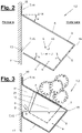
- figure 3 shows a side view of the plant pot holder (1) with an inserted plant pot (21), which protrudes into the trough (9) with a lower section.
- a water filling is present here as an example.
- the water level (S) is here at a higher level in the vertical direction than the lower edge of the plant pot (21) used.
- the plant pot holder (1) is shown in the intended mounting position. It is attached to an object surface (20), which preferably has a vertical orientation.
- the side that is in contact with the surface of the object in the intended attachment position represents the back of the plant pot holder (1).
- the opposite side in the horizontal direction represents the front.
- a longitudinal direction of the plant pot holder extends essentially horizontally along the object surface.
- the longitudinal direction runs essentially parallel to the front edge and rear edges of the top wall (3).
- the plant pot holder (1) has a uniform cross-sectional shape along this longitudinal direction.
- the base body (2) of the plant pot holder (1) comprises an upper wall (3) (wall pointing upwards), a lower wall (4) (wall pointing downwards), a front wall (front intermediate wall (5)) and at least two end walls (6), between which the trough (9) is formed.
- a preferred variant provides that the bottom wall (4) and the front wall (5) are designed to be essentially flat or planar, which enables simple manufacture.
- the lower wall (4) and the front wall (5) can alternatively have a different design. You can particular a uniaxial or have multi-axial curvature or other crowned shape.
- the top wall is preferably flat, at least in the area of the receiving openings (8), so that an annular contact is achieved between a collar on the plant pot (21) and the edge of the receiving opening (8).
- the top wall (4) slopes downwards towards the front and the bottom wall (5) also slopes downwards towards the front. It is therefore an inclined upper wall and an inclined lower wall. Furthermore, according to the example shown, in the fastening position, the front wall (5) slopes downwards towards the rear.
- the angles of inclination (a, b, c) of the top wall, the front wall and/or the bottom wall can be chosen to match an outer contour of the plant pots (21) to be used.
- the angle of inclination can be selected in particular in such a way that essentially uniform distances are achieved between the front wall (5) and a front contour of a plant pot (21) and on the other hand between the lower wall (4) and a bottom contour of the plant pot (21). This is an example in figure 2 shown.
- the inclination of the top wall (3) also has the advantage that any precipitation falling on it (rain, snow, etc.) can run off or slide off towards the front. The precipitation is thus transported away from the object surface (20), which counteracts the formation of moisture damage at the attachment point.
- figure 2 shows a cross-sectional view of the plant pot holder (1) or its base body (2).
- the angles of inclination (a, b, c) of the top wall (3), the bottom wall (4) and the front wall (5) can be selected at will.
- the first angle of inclination (a) of the inclined top wall (4) with respect to a horizontal plane (H) is essentially 30° (angular degrees).
- the first angle of inclination (a) can preferably be between 20° and 50° (angular degrees) relative to a horizontal plane (H).
- the second angle of inclination (b) relative to a horizontal plane (H′) is also essentially 30° (angular degrees) in the examples shown. In other embodiments, it can also preferably be between 20° and 50° (angular degrees) relative to a horizontal plane (H′).
- the first angle of inclination (a) and the second angle of inclination (b) can have essentially the same amount.
- the top wall (3) and the bottom wall (4) can preferably run essentially parallel in the intended fastening position.
- the included angle (belly angle, not marked in the drawings) between the top wall and the front wall is preferably an acute angle.
- the abdominal angle can in particular be between 75° and 90° (angular degrees).
- the angle included between the bottom wall and the front wall is preferably an obtuse angle.
- the ground angle can in particular be between 90° and 115° (angular degrees). Alternatively, other angular amounts are possible.
- figure 2 shows the plant pot holder figure 1 in a cross-sectional view.
- the angles of inclination (a, b, c) of the upper wall (3), the lower wall (4) and the front wall (5) are illustrated again here.
- the inclined front wall (5) preferably has a third angle of inclination (c) to a horizontal plane (H') which is substantially 50° (angular degrees).
- the angle of inclination (c) relative to a horizontal plane (H') can be between 30° and 70° (angular degrees).
- a second strip (15) adjoining essentially vertically upwards (in the fastening position) can be arranged at the rear end of the inclined lower wall (4).
- the second bar (15) can have one or more functions.
- at least one spacer or damper (13) can be arranged on the second strip (15), for example in figure 2 is shown.
- the spacer or damper (13) is preferably attached to the rear-facing surface of the second bar (15).
- a Spacers or dampers (13) can be arranged at a different location or side of the second strip (15) or directly on the rear wall (7).
- a spacer or damper (13) can be dispensed with, which is exemplified in figure 3 is shown.
- the second bar (15) can have any shape and size. According to the preferred embodiment variant in the figures, the second bar (15) ends (in the fastening position) substantially at the level of the front edge (19) between the front wall (5) and the top wall (3), i.e. the height extension of the second bar ( 15) is essentially defined in the fastening position by the height of the front edge (19). Alternatively, a different height profile can be provided.
- the rear wall (7) can be designed in two or more parts and in particular can comprise the first strip (14) and/or the second strip (15).
- the rear wall (7) can be provided between the rear edge of the top wall (3) and the rear edge of the bottom wall (4) at least one bar (15) and also an opening.
- the opening can in particular extend over the entire horizontal length (in the longitudinal direction) of the base body (2). This is advantageous because then the base body (2), which includes the top wall (3), the front wall (5) and the bottom wall (4) and possibly the first and / or the second bar (14, 15), completely in one bending process is producible.
- a rear opening also has advantages for ventilation of the plant pots (21) used in the plant pot holder (1) or the plants and plant substrate contained therein. In particular, the opening prevents a build-up of heat inside the base body, which could otherwise be caused by solar radiation.
- the second bar (15) can form a (partial) delimitation of the trough (9). This case is preferred and shown in the figures.
- the end walls (6) are then preferably connected to the second strip (15), which Figures 2 and 3 is clearly visible.
- the upper edge of the end walls (6) can preferably run at the level of the front edge (19) between the front wall (5) and the top wall (3). Accordingly, it can end essentially flush with the top edge of the second strip (15) on the rear side.
- the front edge (19) between the top wall (3) and the front wall (5), the top edges of the end walls (9) and the top edge of the second strip (15) are provided as the top boundary edges of the trough (9).
- the plant pot holder (1) On the end faces of the base body (2), an area between at least one of the end walls (6) and the upper wall (4) above it can be correspondingly open.
- the plant pot holder (1) preferably has at least one lateral access opening to the trough (9) or to the space enclosed between the top wall, front wall and bottom wall.
- the side opening can advantageously be used to liquid and/or to replenish a fertilizer and/or to act on the above-mentioned moisture-retaining substrate (not shown).
- the at least one side opening promotes air exchange through the interior of the plant pot holder (2). This is particularly advantageous if the plant pot holder (2) is hung outside in the summer and/or is exposed to strong sunlight.
- a wind passing through the side openings can bring about cooling, which is also promoted by the evaporation of liquid from the tub (9) and/or the moisture-storing substrate.
- the wind and/or evaporation-related cooling reduces or prevents premature drying out of the plants used and promotes vegetation.
- the diameter can be, in particular, 10 cm, 11 cm or 12 cm, which is currently the usual collar circumference of plant pots for kitchen herbs and short-lived ornamental plants.
- At least one further opening (17) can be provided in the upper wall (4) (cf. figure 1 ).
- the at least one further opening (17) is preferably considerably smaller than the one or more pot receptacles (8). It can also be used in particular as a pouring opening and/or as a tool holder.
- the plant pot holder (1) can have a water or liquid reservoir (22). This can be of any size and arrangement. According to the example of figure 3 the water reservoir (22) can be arranged one or more times and in particular in an area between the upper wall (3) and the lower wall (4) and to the rear behind at least one pot holder (8).
- the at least one water reservoir (22) can be accessible in particular through one of the further openings (17) mentioned above, in particular in order to fill up and/or clean the water reservoir (22).
- the water reservoir (22) can have a humidification system or irrigation system through which liquid or moisture is released into the tub (9) or the moisture-storing substrate in suitable quantities and at suitable time intervals.
- the delivery can preferably be controllable and/or adjustable.
- separate troughs and/or moistening substrates and/or water reservoirs (22) can be provided for individual pot receptacles (8) and/or groups of pot receptacles (8).
- one or more intermediate walls can be provided, the design and shape of which can be chosen to be the same as or similar to the end walls (6).
- An intermediate wall can be arranged in particular in the longitudinal direction of the plant pot holder (1) between two pot receptacles (8) or between at least one pot receptacle (8) and an adjacent group of pot receptacles (8) or between two adjacent groups of pot receptacles (8).
- a separate water reservoir (22) can be provided for some or all of the tub parts.
- the plant pot holder (1) can include at least one ring-shaped adapter insert (18).
- the adapter insert (18) is preferably provided and adapted to be used in a pot holder (8).
- the outer circumference of the adapter insert (18) can be adapted to the corresponding size of the cup holder (8).
- circular pot receptacles (8) are provided.
- the adapter insert (18) shown has an annular outer circumference.
- the adapter insert (18) can correspondingly have an outer circumference in the shape of a square ring or a circumference in the shape of a rectangular ring.
- the inner circumference of the adapter insert can also be adjusted accordingly to a different cross-sectional contour of a plant pot (21). be adjusted.
- the inner contour can have a round shape, a square shape, a rectangular shape or any other suitable shape.
- the adapter insert (18) can also be used to create a receiving contour that is offset further outwards or inwards than the top wall (3), so that higher or lower plant pots (21) can be used and/or so that the immersion depth of a plant pot (21) in the interior of the plant pot holder (1) and in particular in the tub (9) can be adjustable.
- An overflow opening (10) can be arranged on at least one end wall (6).
- the overflow opening (10) can have any configuration, shape and arrangement.
- the end wall (6) preferably has an upper edge that runs essentially horizontally in the fastening position.
- an overflow opening (10) can be formed by an incision which extends essentially perpendicularly downwards from the upper edge.
- an overflow opening (10) can also be provided in one of the above-mentioned partitions for dividing the tub (9).
- the overflow opening(s) (10) ensure that, for example, rainwater or excess water that has been poured in can drain off in a controlled manner and at a predetermined point.
- water can be distributed into all sections of the trough (9) by introducing water into the trough (9) on one side. It is also avoided that excess water escapes in an uncontrolled manner, for example in the direction of the back, where it could lead to the formation of spots on the object surface (10).
- the plant pot holder (1) and in particular its base (2) can be made of any material.
- a preferred embodiment provides that the top wall, the front wall and the bottom wall and possibly the first and/or second strip (14, 15) are made from a continuous piece of material.
- the base body (2) can preferably be made of a metal, in particular an aluminum sheet. The aluminum sheet can be bent one or more times to form the various wall parts described.
- the end walls (6) can be arranged in any way. They can be connected to at least one edge in one piece with the front wall (5), the bottom wall (6) or the second strip (15). Alternatively, an end wall (6) can be used as a separate wall and attached, for example, by welding. In the examples shown, the end walls (6) are connected by welding to the bottom wall (4), the front wall (5) and possibly the second bar (15).
- the welding tank is preferably designed to be liquid-tight.
- the base body (2) is coated.
- a powder coating and/or a paint finish is particularly suitable for this purpose.
- the coating can serve different purposes. On the one hand, a higher surface load capacity and/or an antibacterial effect can be achieved. The cleanability can also be improved by a coating. On the other hand, the coating can be used to match the color and/or to protect against corrosion.
- the top wall (3), the front wall (5) and the bottom wall (6) are essentially flat.
- At least one of these walls can be crowned. It is also possible, for example, for the front wall (5) and the lower wall (6) to be formed by a plurality of sections which can be connected to one another in an angled or curved manner. Again alternatively, the front wall (5) and the lower wall (6) can be connected, for example, to form a common shell-shaped element, in particular in the form of a semi-cylindrical shell.
- the one or more side openings and/or the rear opening can be omitted.
- the upper edge of the side walls (6) and/or the upper edge of the second strip (15) can be extended upwards to such an extent that they end with the upper wall (3).
- one or more additional covers may be provided to close the side and/or rear opening. This can be indicated, for example, in the winter months in order to better protect the plant pots (21) or the plants contained therein against cold or frost.
- Insulation in particular thermal insulation, can be provided on at least one of the walls (3,4,5,6) mentioned, which in turn can serve as protection against frost or excessive heat in summer.
- the plant pot holder (1) can include one or more attachment adapters so that it can be attached, for example, to a window sill on the outside of the building, a balcony parapet, a railing or a garden fence.
- the at least one fastening adapter is preferably designed for tool-free assembly.
- the plant pot holder (1) can comprise at least one stand, by means of which an object surface (20) is produced according to the examples mentioned above, to which the plant pot holder (1) can be fastened.
- the plant pot holder (1) may be integral with a be connected to such a stand so that it can be set up on the floor or on a tabletop etc.
- two or more pot receptacles (8) and in particular all pot receptacles (8) are arranged in rows on the top wall (3).
- the alignment of the row of pot receptacles is preferably parallel to the longitudinal direction.
- Exactly one row of pot receptacles is preferably provided (cf. figure 1 ).
- two or more rows of cup receptacles can be provided, which in particular can be aligned parallel to one another.
- an arrangement of several pot receptacles in a grid is possible, for example in a square or rectangular grid or in a honeycomb grid.
Landscapes
- Life Sciences & Earth Sciences (AREA)
- Environmental Sciences (AREA)
- Engineering & Computer Science (AREA)
- Water Supply & Treatment (AREA)
- Cultivation Receptacles Or Flower-Pots, Or Pots For Seedlings (AREA)
Claims (15)
- Support de pots de plantes pour la réception d'un ou de plusieurs pots de plantes (21), le support de pots de plantes (1) présentant un corps de base (2) comprenant une paroi supérieure (3), une paroi inférieure (4) et une paroi avant (5), la paroi supérieure (3), la paroi avant (5) et la paroi inférieure (4) étant reliées entre elles d'un seul tenant, et le support de pots de plantes (1) ayant une forme de section transversale (Q) essentiellement uniforme et pouvant être fixé dans la zone d'une paroi côté arrière (7) sur une surface d'objet (20) essentiellement verticale, et la paroi supérieure (3) étant une paroi orientée vers le haut dans la position de fixation et étant inclinée vers le bas en direction du côté avant, et une, deux ou davantage d'ouvertures (8) étant prévues dans la paroi supérieure inclinée (3), lesquelles forment chacune un réceptacle de pot pour un pot de plante (21), et la paroi avant (5) étant une paroi intermédiaire côté avant, qui s'étend entre l'extrémité avant de la paroi supérieure (3) et l'extrémité avant de la paroi inférieure (4), caractérisé en ce que- la paroi inférieure (4) est une paroi orientée vers le bas dans la position de fixation et est inclinée vers le bas en direction du côté avant, et dans lequel- des parois frontales (6) sont agencées aux extrémités frontales du corps de base (2) au moins entre la paroi inférieure inclinée (4) et la paroi avant (5), et dans lequel- une cuve (9) étanche aux liquides est formée entre les parois frontales (6), la paroi inférieure (4) et la paroi avant (5).
- Support de pots de plantes selon la revendication 1, dans lequel, sur les côtés frontaux du corps de base (2), une zone est ouverte entre au moins une paroi frontale (6) et la paroi supérieure (4) située au-dessus.
- Support de pots de plantes selon la revendication 1 ou 2, dans lequel- la paroi supérieure inclinée (3), dans la position de fixation, a un premier angle d'inclinaison (a) par rapport à un plan horizontal (H) compris entre 20° et 50°, notamment d'essentiellement 30° ; ET/OU- la paroi inférieure inclinée (4), dans la position de fixation, a un deuxième angle d'inclinaison (b) par rapport à un plan horizontal (H') compris entre 20° et 50°, notamment d'essentiellement 30° ; ET/OU dans lequel- la paroi avant inclinée a un troisième angle d'inclinaison (c) par rapport à un plan horizontal (H') compris entre 30° et 70°, notamment d'essentiellement 50°.
- Support de pots de plantes selon l'une quelconque des revendications précédentes, dans lequel- une première baguette (14) se raccordant essentiellement verticalement vers le haut est agencée à l'extrémité côté arrière de la paroi supérieure inclinée (4) ; ET/OU dans lequel- une deuxième baguette (15) se raccordant essentiellement verticalement vers le haut est agencée à l'extrémité côté arrière de la paroi inférieure (4).
- Support de pots de plantes selon la revendication précédente, dans lequel la deuxième baguette (15) se termine essentiellement au niveau du bord côté avant (19) entre la paroi avant (5) et la paroi supérieure (3) et dans lequel, notamment, les parois frontales (6) sont reliées à la deuxième baguette (15) et un bord supérieur des parois frontales (6) s'étend essentiellement au niveau du bord côté avant (19) entre la paroi avant (5) et la paroi supérieure (3).
- Support de pots de plantes selon l'une quelconque des revendications précédentes, dans lequel la paroi côté arrière (7) est configurée en deux parties ou plus et comprend notamment la première baguette (14) et/ou la deuxième baguette (15).
- Support de pots de plantes selon l'une quelconque des revendications précédentes, dans lequel- une structure de fixation (16) est agencée à l'extrémité côté arrière de la paroi supérieure (4) ou sur la première baguette (14) ; ET/OU dans lequel- au moins un espaceur ou un amortisseur (13) est agencé sur la paroi côté arrière (7), notamment sur la deuxième baguette (15).
- Support de pots de plantes selon l'une quelconque des revendications précédentes, dans lequel au moins une ouverture supplémentaire (17) est prévue dans la paroi supérieure (4), laquelle est notamment nettement plus petite qu'un réceptacle de pot (8) et sert en outre notamment d'ouverture d'arrosage et/ou de réceptacle d'outil.
- Support de pots de plantes selon l'une quelconque des revendications précédentes, dans lequel au moins un réceptacle de pot (8) et notamment tous les réceptacles de pot (8)- a/ont une forme ronde, ou- a/ont une forme carrée, ou- a/ont une forme rectangulaire.
- Support de pots de plantes selon l'une quelconque des revendications précédentes, dans lequel le support de pots de plantes comprend au moins un insert adaptateur annulaire (18) qui peut être inséré dans un réceptacle de pot (8), la circonférence extérieure de l'insert adaptateur étant adaptée à la taille du réceptacle de pot.
- Support de pots de plantes selon l'une quelconque des revendications précédentes, dans lequel- le corps de base est fabriqué en un métal, notamment en une tôle d'aluminium ; ET/OU dans lequel- le corps de base est revêtu, et notamment comprend un revêtement en poudre ou un vernissage.
- Support de pots de plantes selon l'une quelconque des revendications précédentes, dans lequel- une paroi frontale (6) présente un bord supérieur s'étendant essentiellement horizontalement dans la position de fixation ; ET/OU dans lequel- une ouverture de trop-plein (10) est agencée sur au moins une paroi frontale (6) ; ET/OU dans lequel- les parois frontales (6) sont reliées à la paroi inférieure (4), à la paroi avant (5) et éventuellement à la deuxième baguette (15) de manière étanche aux liquides, notamment par soudage.
- Support de pots de plantes selon l'une quelconque des revendications précédentes, dans lequel le support de pots de plantes présente au moins un réservoir d'eau (22) .
- Support de pots de plantes selon l'une quelconque des revendications précédentes, dans lequel le support de pots de plantes présente au moins une paroi intermédiaire qui divise notamment le bac (9) dans la direction longitudinale.
- Support de pots de plantes selon l'une quelconque des revendications précédentes, dans lequel une paroi intermédiaire est agencée entre deux réceptacles de pots (8) dans la direction longitudinale du support de pots de plantes (1).
Applications Claiming Priority (1)
| Application Number | Priority Date | Filing Date | Title |
|---|---|---|---|
| DE202019102283.3U DE202019102283U1 (de) | 2019-04-23 | 2019-04-23 | Pflanztopfhalter |
Publications (2)
| Publication Number | Publication Date |
|---|---|
| EP3730004A1 EP3730004A1 (fr) | 2020-10-28 |
| EP3730004B1 true EP3730004B1 (fr) | 2022-04-06 |
Family
ID=70470781
Family Applications (1)
| Application Number | Title | Priority Date | Filing Date |
|---|---|---|---|
| EP20171160.3A Active EP3730004B1 (fr) | 2019-04-23 | 2020-04-23 | Porte-pot pour la culture de plantes |
Country Status (2)
| Country | Link |
|---|---|
| EP (1) | EP3730004B1 (fr) |
| DE (1) | DE202019102283U1 (fr) |
Families Citing this family (2)
| Publication number | Priority date | Publication date | Assignee | Title |
|---|---|---|---|---|
| DE102020134776B4 (de) * | 2020-12-22 | 2023-05-25 | urbanhive GmbH | Modulares System für Hydrokulturen für den Einsatz im Innenraum |
| CN115530063A (zh) * | 2022-09-28 | 2022-12-30 | 曹艳 | 一种使用无土栽培机制的西洋参栽培设备 |
Family Cites Families (11)
| Publication number | Priority date | Publication date | Assignee | Title |
|---|---|---|---|---|
| DE8118605U1 (de) | 1981-06-26 | 1981-11-12 | TWL International Hydrokultur GmbH, 6090 Rüsselsheim | "einsatzeinheit aus pflanztopf und manschette" |
| DE29601114U1 (de) | 1996-01-24 | 1996-04-04 | Hausmann Hermann | Variabel verstellbarer Pflanztopfhalter |
| US20020157308A1 (en) * | 2001-04-26 | 2002-10-31 | Hanis John A. | Display case |
| DE202005018519U1 (de) | 2005-11-26 | 2007-04-05 | Geobra Brandstätter GmbH & Co. KG | Pflanztopf-Anordnung |
| DE202005020177U1 (de) | 2005-12-24 | 2007-05-10 | Pöppelmann Holding GmbH & Co. KG | Steige und Pflanztopf |
| FR2951906B1 (fr) * | 2009-10-30 | 2012-07-13 | Santos Jose Dos | Dispositif pour un agencement vertical ou incline de culture hors sol de vegetaux |
| WO2011136842A1 (fr) * | 2010-04-26 | 2011-11-03 | Baker Richard L | Jardinière verticale |
| EP2564690A1 (fr) | 2011-09-05 | 2013-03-06 | Plastia s.r.o. | Agencement de pot à plante doté d'une partie supérieure et d'un pot d'insertion pouvant être inséré dans et retiré de la partie supérieure |
| CN102640674A (zh) * | 2012-04-06 | 2012-08-22 | 东莞长欣电子科技有限公司 | 一种环保绿化墙架结构 |
| CN106069266A (zh) * | 2016-06-14 | 2016-11-09 | 深圳市雅茵园花木中心 | 一种智能种植系统及立体种植装置 |
| TW201824992A (zh) | 2017-01-03 | 2018-07-16 | 譽蒼生物科技股份有限公司 | 植栽盆體及植栽端盤 |
-
2019
- 2019-04-23 DE DE202019102283.3U patent/DE202019102283U1/de active Active
-
2020
- 2020-04-23 EP EP20171160.3A patent/EP3730004B1/fr active Active
Also Published As
| Publication number | Publication date |
|---|---|
| DE202019102283U1 (de) | 2020-07-31 |
| EP3730004A1 (fr) | 2020-10-28 |
Similar Documents
| Publication | Publication Date | Title |
|---|---|---|
| EP2274971B1 (fr) | Dispositif de tuteurage et d'irrigation | |
| EP3481736B1 (fr) | Récipient empilable comprenant des moyens d'évacuation de liquide du côté du fond | |
| EP3730004B1 (fr) | Porte-pot pour la culture de plantes | |
| DE202011111001U1 (de) | Ein Pflanzenbewässerungssystem | |
| DE2043199A1 (de) | Blumenkasten | |
| EP0201548A1 (fr) | Agencement de plantes | |
| DE202004000438U1 (de) | Anordnung zur Fassadenbegrünung | |
| DE102013112980B4 (de) | Vorrichtung zum Kultivieren und Halten von Pflanzen in einem organischen oder anorganischen Substrat für Pflanzgefäße zur Herstellung eines Vegetationsraums | |
| DE602005005696T2 (de) | Pflanzentopf | |
| EP1895061A2 (fr) | Récipient de collecte d'eau de pluie | |
| DE102009026513B4 (de) | Topfanordnung für Pflanzen, insbesondere für Orchideen | |
| DE102014107465B3 (de) | Behälter für Wasserpflanzen | |
| DE202013009914U1 (de) | Vorrichtung zum Kultivieren und Halten von Pflanzen in einem organischen oder anorganischen Substrat für Pflanzgefäße zur Herstellung eines Vegetationsraums | |
| DE202006013388U1 (de) | Pflanzenbehälter | |
| AT523730B1 (de) | Pflanzungsvorrichtung | |
| AT257255B (de) | Einrichtung für hydroponische Pflanzenzucht, insbesodere des Grünfutters | |
| DE102012020379B4 (de) | Mehrfachfunktionsgefäß, insbesondere zum gleichzeitigen Anordnen von Pflanzen und Nisthöhlen, Tränken und Futterstellen für Wildvögel | |
| DE102015209344B3 (de) | Pflanzgefäß mit Wassermanagementsystem | |
| DE202022106208U1 (de) | Hochbeet-Anlage und diesbezügliches Hochbeet-Anlagensystem | |
| AT412139B (de) | Modulares behältersystem | |
| WO2004030444A1 (fr) | Systeme de bacs modulaire pour la culture de plantes | |
| WO2023126093A1 (fr) | Structure de couche surélevée et système de couche surélevée correspondant | |
| EP3050427A1 (fr) | Jardinière | |
| DE4233620C2 (de) | Pflanzenversorgungsvorrichtung | |
| EP1287734A2 (fr) | Grands conteneurs à plantes pour façades de bâtiments |
Legal Events
| Date | Code | Title | Description |
|---|---|---|---|
| PUAI | Public reference made under article 153(3) epc to a published international application that has entered the european phase |
Free format text: ORIGINAL CODE: 0009012 |
|
| STAA | Information on the status of an ep patent application or granted ep patent |
Free format text: STATUS: THE APPLICATION HAS BEEN PUBLISHED |
|
| AK | Designated contracting states |
Kind code of ref document: A1 Designated state(s): AL AT BE BG CH CY CZ DE DK EE ES FI FR GB GR HR HU IE IS IT LI LT LU LV MC MK MT NL NO PL PT RO RS SE SI SK SM TR |
|
| AX | Request for extension of the european patent |
Extension state: BA ME |
|
| STAA | Information on the status of an ep patent application or granted ep patent |
Free format text: STATUS: REQUEST FOR EXAMINATION WAS MADE |
|
| 17P | Request for examination filed |
Effective date: 20210426 |
|
| RBV | Designated contracting states (corrected) |
Designated state(s): AL AT BE BG CH CY CZ DE DK EE ES FI FR GB GR HR HU IE IS IT LI LT LU LV MC MK MT NL NO PL PT RO RS SE SI SK SM TR |
|
| GRAP | Despatch of communication of intention to grant a patent |
Free format text: ORIGINAL CODE: EPIDOSNIGR1 |
|
| RIC1 | Information provided on ipc code assigned before grant |
Ipc: A01G 27/02 20060101ALI20210920BHEP Ipc: A01G 9/02 20180101ALI20210920BHEP Ipc: A47F 7/28 20060101ALI20210920BHEP Ipc: A47F 7/00 20060101AFI20210920BHEP |
|
| STAA | Information on the status of an ep patent application or granted ep patent |
Free format text: STATUS: GRANT OF PATENT IS INTENDED |
|
| INTG | Intention to grant announced |
Effective date: 20211028 |
|
| GRAS | Grant fee paid |
Free format text: ORIGINAL CODE: EPIDOSNIGR3 |
|
| GRAA | (expected) grant |
Free format text: ORIGINAL CODE: 0009210 |
|
| STAA | Information on the status of an ep patent application or granted ep patent |
Free format text: STATUS: THE PATENT HAS BEEN GRANTED |
|
| AK | Designated contracting states |
Kind code of ref document: B1 Designated state(s): AL AT BE BG CH CY CZ DE DK EE ES FI FR GB GR HR HU IE IS IT LI LT LU LV MC MK MT NL NO PL PT RO RS SE SI SK SM TR |
|
| REG | Reference to a national code |
Ref country code: GB Ref legal event code: FG4D Free format text: NOT ENGLISH |
|
| REG | Reference to a national code |
Ref country code: CH Ref legal event code: EP |
|
| REG | Reference to a national code |
Ref country code: AT Ref legal event code: REF Ref document number: 1480489 Country of ref document: AT Kind code of ref document: T Effective date: 20220415 |
|
| REG | Reference to a national code |
Ref country code: IE Ref legal event code: FG4D Free format text: LANGUAGE OF EP DOCUMENT: GERMAN |
|
| REG | Reference to a national code |
Ref country code: DE Ref legal event code: R096 Ref document number: 502020000894 Country of ref document: DE |
|
| REG | Reference to a national code |
Ref country code: LT Ref legal event code: MG9D |
|
| REG | Reference to a national code |
Ref country code: NL Ref legal event code: MP Effective date: 20220406 |
|
| PG25 | Lapsed in a contracting state [announced via postgrant information from national office to epo] |
Ref country code: NL Free format text: LAPSE BECAUSE OF FAILURE TO SUBMIT A TRANSLATION OF THE DESCRIPTION OR TO PAY THE FEE WITHIN THE PRESCRIBED TIME-LIMIT Effective date: 20220406 |
|
| PG25 | Lapsed in a contracting state [announced via postgrant information from national office to epo] |
Ref country code: SE Free format text: LAPSE BECAUSE OF FAILURE TO SUBMIT A TRANSLATION OF THE DESCRIPTION OR TO PAY THE FEE WITHIN THE PRESCRIBED TIME-LIMIT Effective date: 20220406 Ref country code: PT Free format text: LAPSE BECAUSE OF FAILURE TO SUBMIT A TRANSLATION OF THE DESCRIPTION OR TO PAY THE FEE WITHIN THE PRESCRIBED TIME-LIMIT Effective date: 20220808 Ref country code: NO Free format text: LAPSE BECAUSE OF FAILURE TO SUBMIT A TRANSLATION OF THE DESCRIPTION OR TO PAY THE FEE WITHIN THE PRESCRIBED TIME-LIMIT Effective date: 20220706 Ref country code: LT Free format text: LAPSE BECAUSE OF FAILURE TO SUBMIT A TRANSLATION OF THE DESCRIPTION OR TO PAY THE FEE WITHIN THE PRESCRIBED TIME-LIMIT Effective date: 20220406 Ref country code: HR Free format text: LAPSE BECAUSE OF FAILURE TO SUBMIT A TRANSLATION OF THE DESCRIPTION OR TO PAY THE FEE WITHIN THE PRESCRIBED TIME-LIMIT Effective date: 20220406 Ref country code: GR Free format text: LAPSE BECAUSE OF FAILURE TO SUBMIT A TRANSLATION OF THE DESCRIPTION OR TO PAY THE FEE WITHIN THE PRESCRIBED TIME-LIMIT Effective date: 20220707 Ref country code: FI Free format text: LAPSE BECAUSE OF FAILURE TO SUBMIT A TRANSLATION OF THE DESCRIPTION OR TO PAY THE FEE WITHIN THE PRESCRIBED TIME-LIMIT Effective date: 20220406 Ref country code: ES Free format text: LAPSE BECAUSE OF FAILURE TO SUBMIT A TRANSLATION OF THE DESCRIPTION OR TO PAY THE FEE WITHIN THE PRESCRIBED TIME-LIMIT Effective date: 20220406 Ref country code: BG Free format text: LAPSE BECAUSE OF FAILURE TO SUBMIT A TRANSLATION OF THE DESCRIPTION OR TO PAY THE FEE WITHIN THE PRESCRIBED TIME-LIMIT Effective date: 20220706 |
|
| PG25 | Lapsed in a contracting state [announced via postgrant information from national office to epo] |
Ref country code: RS Free format text: LAPSE BECAUSE OF FAILURE TO SUBMIT A TRANSLATION OF THE DESCRIPTION OR TO PAY THE FEE WITHIN THE PRESCRIBED TIME-LIMIT Effective date: 20220406 Ref country code: PL Free format text: LAPSE BECAUSE OF FAILURE TO SUBMIT A TRANSLATION OF THE DESCRIPTION OR TO PAY THE FEE WITHIN THE PRESCRIBED TIME-LIMIT Effective date: 20220406 Ref country code: LV Free format text: LAPSE BECAUSE OF FAILURE TO SUBMIT A TRANSLATION OF THE DESCRIPTION OR TO PAY THE FEE WITHIN THE PRESCRIBED TIME-LIMIT Effective date: 20220406 Ref country code: IS Free format text: LAPSE BECAUSE OF FAILURE TO SUBMIT A TRANSLATION OF THE DESCRIPTION OR TO PAY THE FEE WITHIN THE PRESCRIBED TIME-LIMIT Effective date: 20220806 |
|
| REG | Reference to a national code |
Ref country code: BE Ref legal event code: MM Effective date: 20220430 |
|
| REG | Reference to a national code |
Ref country code: DE Ref legal event code: R097 Ref document number: 502020000894 Country of ref document: DE |
|
| PG25 | Lapsed in a contracting state [announced via postgrant information from national office to epo] |
Ref country code: SM Free format text: LAPSE BECAUSE OF FAILURE TO SUBMIT A TRANSLATION OF THE DESCRIPTION OR TO PAY THE FEE WITHIN THE PRESCRIBED TIME-LIMIT Effective date: 20220406 Ref country code: SK Free format text: LAPSE BECAUSE OF FAILURE TO SUBMIT A TRANSLATION OF THE DESCRIPTION OR TO PAY THE FEE WITHIN THE PRESCRIBED TIME-LIMIT Effective date: 20220406 Ref country code: RO Free format text: LAPSE BECAUSE OF FAILURE TO SUBMIT A TRANSLATION OF THE DESCRIPTION OR TO PAY THE FEE WITHIN THE PRESCRIBED TIME-LIMIT Effective date: 20220406 Ref country code: MC Free format text: LAPSE BECAUSE OF FAILURE TO SUBMIT A TRANSLATION OF THE DESCRIPTION OR TO PAY THE FEE WITHIN THE PRESCRIBED TIME-LIMIT Effective date: 20220406 Ref country code: LU Free format text: LAPSE BECAUSE OF NON-PAYMENT OF DUE FEES Effective date: 20220423 Ref country code: EE Free format text: LAPSE BECAUSE OF FAILURE TO SUBMIT A TRANSLATION OF THE DESCRIPTION OR TO PAY THE FEE WITHIN THE PRESCRIBED TIME-LIMIT Effective date: 20220406 Ref country code: DK Free format text: LAPSE BECAUSE OF FAILURE TO SUBMIT A TRANSLATION OF THE DESCRIPTION OR TO PAY THE FEE WITHIN THE PRESCRIBED TIME-LIMIT Effective date: 20220406 Ref country code: CZ Free format text: LAPSE BECAUSE OF FAILURE TO SUBMIT A TRANSLATION OF THE DESCRIPTION OR TO PAY THE FEE WITHIN THE PRESCRIBED TIME-LIMIT Effective date: 20220406 |
|
| PLBE | No opposition filed within time limit |
Free format text: ORIGINAL CODE: 0009261 |
|
| STAA | Information on the status of an ep patent application or granted ep patent |
Free format text: STATUS: NO OPPOSITION FILED WITHIN TIME LIMIT |
|
| PG25 | Lapsed in a contracting state [announced via postgrant information from national office to epo] |
Ref country code: BE Free format text: LAPSE BECAUSE OF NON-PAYMENT OF DUE FEES Effective date: 20220430 |
|
| 26N | No opposition filed |
Effective date: 20230110 |
|
| PG25 | Lapsed in a contracting state [announced via postgrant information from national office to epo] |
Ref country code: AL Free format text: LAPSE BECAUSE OF FAILURE TO SUBMIT A TRANSLATION OF THE DESCRIPTION OR TO PAY THE FEE WITHIN THE PRESCRIBED TIME-LIMIT Effective date: 20220406 |
|
| PG25 | Lapsed in a contracting state [announced via postgrant information from national office to epo] |
Ref country code: IE Free format text: LAPSE BECAUSE OF NON-PAYMENT OF DUE FEES Effective date: 20220423 |
|
| PG25 | Lapsed in a contracting state [announced via postgrant information from national office to epo] |
Ref country code: SI Free format text: LAPSE BECAUSE OF FAILURE TO SUBMIT A TRANSLATION OF THE DESCRIPTION OR TO PAY THE FEE WITHIN THE PRESCRIBED TIME-LIMIT Effective date: 20220406 |
|
| PGFP | Annual fee paid to national office [announced via postgrant information from national office to epo] |
Ref country code: FR Payment date: 20230424 Year of fee payment: 4 Ref country code: DE Payment date: 20230426 Year of fee payment: 4 Ref country code: CH Payment date: 20230502 Year of fee payment: 4 |
|
| PG25 | Lapsed in a contracting state [announced via postgrant information from national office to epo] |
Ref country code: IT Free format text: LAPSE BECAUSE OF FAILURE TO SUBMIT A TRANSLATION OF THE DESCRIPTION OR TO PAY THE FEE WITHIN THE PRESCRIBED TIME-LIMIT Effective date: 20220406 |
|
| PG25 | Lapsed in a contracting state [announced via postgrant information from national office to epo] |
Ref country code: MK Free format text: LAPSE BECAUSE OF FAILURE TO SUBMIT A TRANSLATION OF THE DESCRIPTION OR TO PAY THE FEE WITHIN THE PRESCRIBED TIME-LIMIT Effective date: 20220406 Ref country code: CY Free format text: LAPSE BECAUSE OF FAILURE TO SUBMIT A TRANSLATION OF THE DESCRIPTION OR TO PAY THE FEE WITHIN THE PRESCRIBED TIME-LIMIT Effective date: 20220406 |