EP3730004B1 - Plant pot holder - Google Patents
Plant pot holder Download PDFInfo
- Publication number
- EP3730004B1 EP3730004B1 EP20171160.3A EP20171160A EP3730004B1 EP 3730004 B1 EP3730004 B1 EP 3730004B1 EP 20171160 A EP20171160 A EP 20171160A EP 3730004 B1 EP3730004 B1 EP 3730004B1
- Authority
- EP
- European Patent Office
- Prior art keywords
- wall
- plant
- pot holder
- pot
- holder according
- Prior art date
- Legal status (The legal status is an assumption and is not a legal conclusion. Google has not performed a legal analysis and makes no representation as to the accuracy of the status listed.)
- Active
Links
- XLYOFNOQVPJJNP-UHFFFAOYSA-N water Substances O XLYOFNOQVPJJNP-UHFFFAOYSA-N 0.000 claims description 24
- 125000006850 spacer group Chemical group 0.000 claims description 6
- 239000011248 coating agent Substances 0.000 claims description 5
- 238000000576 coating method Methods 0.000 claims description 5
- 238000005580 one pot reaction Methods 0.000 claims description 4
- 238000003466 welding Methods 0.000 claims description 4
- 229910052782 aluminium Inorganic materials 0.000 claims description 3
- XAGFODPZIPBFFR-UHFFFAOYSA-N aluminium Chemical compound [Al] XAGFODPZIPBFFR-UHFFFAOYSA-N 0.000 claims description 3
- 229910052751 metal Inorganic materials 0.000 claims description 2
- 239000002184 metal Substances 0.000 claims description 2
- 239000003973 paint Substances 0.000 claims description 2
- 239000000843 powder Substances 0.000 claims description 2
- 239000004411 aluminium Substances 0.000 claims 1
- 239000002966 varnish Substances 0.000 claims 1
- 239000000758 substrate Substances 0.000 description 9
- 235000008216 herbs Nutrition 0.000 description 6
- 239000007788 liquid Substances 0.000 description 5
- 239000000463 material Substances 0.000 description 5
- 238000003973 irrigation Methods 0.000 description 3
- 230000002262 irrigation Effects 0.000 description 3
- 238000005192 partition Methods 0.000 description 3
- 239000004033 plastic Substances 0.000 description 3
- 229920003023 plastic Polymers 0.000 description 3
- 230000015572 biosynthetic process Effects 0.000 description 2
- 238000001816 cooling Methods 0.000 description 2
- 238000001704 evaporation Methods 0.000 description 2
- 230000008020 evaporation Effects 0.000 description 2
- 239000003337 fertilizer Substances 0.000 description 2
- 238000009413 insulation Methods 0.000 description 2
- 238000000034 method Methods 0.000 description 2
- 238000012986 modification Methods 0.000 description 2
- 230000004048 modification Effects 0.000 description 2
- 238000001556 precipitation Methods 0.000 description 2
- 210000001015 abdomen Anatomy 0.000 description 1
- 230000003187 abdominal effect Effects 0.000 description 1
- 230000002745 absorbent Effects 0.000 description 1
- 239000002250 absorbent Substances 0.000 description 1
- 230000001154 acute effect Effects 0.000 description 1
- 239000000654 additive Substances 0.000 description 1
- 230000000996 additive effect Effects 0.000 description 1
- 230000000844 anti-bacterial effect Effects 0.000 description 1
- 238000005452 bending Methods 0.000 description 1
- 239000004927 clay Substances 0.000 description 1
- 230000007797 corrosion Effects 0.000 description 1
- 238000005260 corrosion Methods 0.000 description 1
- 230000001419 dependent effect Effects 0.000 description 1
- 238000011161 development Methods 0.000 description 1
- 230000018109 developmental process Effects 0.000 description 1
- 238000001035 drying Methods 0.000 description 1
- 235000013399 edible fruits Nutrition 0.000 description 1
- 230000002349 favourable effect Effects 0.000 description 1
- 235000013305 food Nutrition 0.000 description 1
- 239000008187 granular material Substances 0.000 description 1
- 238000003306 harvesting Methods 0.000 description 1
- 238000007654 immersion Methods 0.000 description 1
- NLYAJNPCOHFWQQ-UHFFFAOYSA-N kaolin Chemical compound O.O.O=[Al]O[Si](=O)O[Si](=O)O[Al]=O NLYAJNPCOHFWQQ-UHFFFAOYSA-N 0.000 description 1
- 238000004519 manufacturing process Methods 0.000 description 1
- 235000015097 nutrients Nutrition 0.000 description 1
- 230000002028 premature Effects 0.000 description 1
- 230000005855 radiation Effects 0.000 description 1
- 239000002689 soil Substances 0.000 description 1
- 239000007921 spray Substances 0.000 description 1
- 239000004575 stone Substances 0.000 description 1
- 238000009423 ventilation Methods 0.000 description 1
Images

Classifications
-
- A—HUMAN NECESSITIES
- A47—FURNITURE; DOMESTIC ARTICLES OR APPLIANCES; COFFEE MILLS; SPICE MILLS; SUCTION CLEANERS IN GENERAL
- A47F—SPECIAL FURNITURE, FITTINGS, OR ACCESSORIES FOR SHOPS, STOREHOUSES, BARS, RESTAURANTS OR THE LIKE; PAYING COUNTERS
- A47F7/00—Show stands, hangers, or shelves, adapted for particular articles or materials
- A47F7/0071—Show stands, hangers, or shelves, adapted for particular articles or materials for perishable goods
- A47F7/0078—Show stands, hangers, or shelves, adapted for particular articles or materials for perishable goods for plants or flowers
-
- A—HUMAN NECESSITIES
- A01—AGRICULTURE; FORESTRY; ANIMAL HUSBANDRY; HUNTING; TRAPPING; FISHING
- A01G—HORTICULTURE; CULTIVATION OF VEGETABLES, FLOWERS, RICE, FRUIT, VINES, HOPS OR SEAWEED; FORESTRY; WATERING
- A01G27/00—Self-acting watering devices, e.g. for flower-pots
- A01G27/02—Self-acting watering devices, e.g. for flower-pots having a water reservoir, the main part thereof being located wholly around or directly beside the growth substrate
-
- A—HUMAN NECESSITIES
- A01—AGRICULTURE; FORESTRY; ANIMAL HUSBANDRY; HUNTING; TRAPPING; FISHING
- A01G—HORTICULTURE; CULTIVATION OF VEGETABLES, FLOWERS, RICE, FRUIT, VINES, HOPS OR SEAWEED; FORESTRY; WATERING
- A01G9/00—Cultivation in receptacles, forcing-frames or greenhouses; Edging for beds, lawn or the like
- A01G9/02—Receptacles, e.g. flower-pots or boxes; Glasses for cultivating flowers
- A01G9/022—Pots for vertical horticulture
- A01G9/025—Containers and elements for greening walls
-
- A—HUMAN NECESSITIES
- A47—FURNITURE; DOMESTIC ARTICLES OR APPLIANCES; COFFEE MILLS; SPICE MILLS; SUCTION CLEANERS IN GENERAL
- A47F—SPECIAL FURNITURE, FITTINGS, OR ACCESSORIES FOR SHOPS, STOREHOUSES, BARS, RESTAURANTS OR THE LIKE; PAYING COUNTERS
- A47F7/00—Show stands, hangers, or shelves, adapted for particular articles or materials
- A47F7/28—Show stands, hangers, or shelves, adapted for particular articles or materials for containers, e.g. flasks, bottles, tins, milk packs
- A47F7/283—Show stands or the like having a compartment for each container
-
- Y—GENERAL TAGGING OF NEW TECHNOLOGICAL DEVELOPMENTS; GENERAL TAGGING OF CROSS-SECTIONAL TECHNOLOGIES SPANNING OVER SEVERAL SECTIONS OF THE IPC; TECHNICAL SUBJECTS COVERED BY FORMER USPC CROSS-REFERENCE ART COLLECTIONS [XRACs] AND DIGESTS
- Y02—TECHNOLOGIES OR APPLICATIONS FOR MITIGATION OR ADAPTATION AGAINST CLIMATE CHANGE
- Y02P—CLIMATE CHANGE MITIGATION TECHNOLOGIES IN THE PRODUCTION OR PROCESSING OF GOODS
- Y02P60/00—Technologies relating to agriculture, livestock or agroalimentary industries
- Y02P60/20—Reduction of greenhouse gas [GHG] emissions in agriculture, e.g. CO2
Definitions
- the present disclosure relates to a plant pot holder for holding one or more plant pots.
- Plants, especially kitchen herbs and smaller ornamental plants, are often commercially available in a plant pot that has a simple design.
- the plant pot often has an essentially cylindrical outer shape and consists of a thin deep-drawn plastic material. In some cases, plant pots with other basic shapes are also available.
- the plant pots usually have a round collar on the upper edge.
- the purchaser will typically remove the plant from the plant pot and transplant it into another vessel of higher quality.
- the buyer can place the plant together with the simple plastic plant pot in a higher-quality and attractive cachepot.
- the cachepot or the higher-quality planter is then usually placed on a flat surface, in the case of kitchen herbs in particular on the kitchen worktop, a window sill or a balcony or terrace table.
- the previously known plant pot holders are not optimally designed.
- a crate is known in which a plurality of plant pots can be used in a grid arrangement.
- the crate has to be parked in a large open area and does not offer an attractive overall aesthetic impression.
- the crate is not suitable for use in the private sector.
- WO 2007/073843 A1 discloses another embodiment of a crate with several troughs for holding plant pots.
- the crate here is formed from a foamed plastics material and has an unpleasing appearance.
- the crate in which a plurality of plant pots are arranged in a grid, for example, has to be placed on a large area.
- cover pots and sleeves for receiving a single plant pot and for producing a more attractive appearance are known, for example from EP 1 790 212 B1 , DE 81 18 605 U1 as EP 2 753 167 B1 .
- a planting device for forming a so-called "green wall” comprises a plurality of planting device units which can be plugged one above the other and which each have a plurality of inclined screens with openings into which plant pots can be inserted.
- Below the planter units is a separate water reservoir provided, in which a pump can be arranged.
- a pump can be arranged below the planter units.
- the water from the water reservoir is pumped up to the planter units via hoses and delivered to the plants via drip lines or spray devices. Excess water drains down within the planter units and is collected centrally in the water reservoir.
- the planter units have a closed box structure.
- CN106069266A discloses a plant pot holder with a reservoir.
- CN102640674A discloses a plant pot holder for drip irrigation.
- the invention solves this problem with the features of the main claim.
- the plant pot holder according to the present disclosure is designed to hold one or preferably several plant pots.
- the plant pot holder has a base body that can be fastened to a substantially vertical object surface in the area of a rear wall.
- the base body therefore does not need to be placed on a flat or horizontal surface. Rather, it is possible to attach it, for example, to a free wall surface in the kitchen, or, for example, to a parapet or railing on the balcony, or to a side wall of a building or a piece of furniture.
- the plant pot holder is designed and intended to be attached to an external window sill.
- a customer can place the plant pot holder in particular on the outside of his kitchen window. Herbs or other kitchen plants can then be used in the plant pot holder together with the purchased plant pot and are therefore always directly accessible.
- the base body has a uniform cross-sectional shape with a wall pointing upwards in the intended fastening position (hereinafter referred to as the upper wall), a wall pointing downwards in the fastening position (hereinafter referred to as the lower wall) and a front intermediate wall (hereinafter referred to as the front wall).
- the front wall extends between the top wall and the bottom wall.
- the top wall and the bottom wall may each have a front end, preferably with the front wall extending between those ends.
- the top wall, front wall and bottom wall are connected to one another in one piece.
- the top wall slopes downward toward the front.
- One, two or more openings are provided in the inclined top wall, each of which forms a pot receptacle for a plant pot.
- a pot holder for holding two or more plant pots, in particular for a group of plant pots, can be provided.
- the inclined arrangement of the top wall in the fastening position has several advantages.
- the top of the plant pot is tilted towards the front, i.e. towards the customer / user, so that the plant is more visible and therefore presented in a more aesthetically pleasing way.
- accessibility to the plant is improved, which is particularly helpful for quickly harvesting leaves, stems, flowers, roots or other plant parts.
- the bottom wall is also inclined downwards towards the front.
- end walls are arranged at the end ends of the main body (ie, at the outer ends in the longitudinal direction) between the inclined bottom wall and the front wall.
- the end walls preferably run essentially transversely to the bottom wall and to the front wall thus essentially vertical in the fastening position.
- an inclined course can be provided.
- a trough is thus formed between the end walls, the inclined lower wall and the front wall.
- the front wall, the bottom wall and the end walls are arranged and connected to one another in such a way that they form a liquid-tight trough in the intended attachment position, in particular a liquid-tight trough at the bottom and to the side.
- An inserted plant pot preferably protrudes at least partially into this trough.
- the tub can be filled with water and possibly a fertilizer additive.
- a plant pot that is inserted into the plant pot holder preferably protrudes (only) with a lower section into the tub.
- the plant located in the plant pot or the surrounding plant substrate can thus dip a little into the water contained in the tub, so that the plant contained in a plant pot is supplied with water and nutrients in a simple manner.
- the trough can be partially or completely filled with a moistening substrate, for example with an absorbent sponge, expanded clay, water-storing granules or some other suitable liquid-storing material.
- a moistening substrate for example with an absorbent sponge, expanded clay, water-storing granules or some other suitable liquid-storing material.
- the tub can be filled in such a way that sufficient contact between the one hand, the plant pot or the plant substrate contained therein (soil) or the Plant and on the other hand the humidification substrate is guaranteed.
- the front wall of the plant pot holder can preferably be inclined downwards towards the rear. This achieves a slim and space-saving structure.
- the plant pot holder can be attached in any way.
- a suitable fastening structure for example a screw receptacle, is preferably arranged at the rear end of the top wall.
- a fastening structure can also include a one-piece or multi-piece fixing means, with which it can be fixed, for example, to a window sill, a window reveal, a railing or a parapet.
- a first bar which connects essentially vertically upwards is arranged at the rear end of the inclined upper wall.
- the first bar can be part of the base body.
- the fastening structure can preferably be accommodated on or in this first bar.
- FIG. 1 A preferred embodiment of the plant pot holder according to the present disclosure is in figure 1 shown.
- the illustration shows a perspective view of a plant pot holder (1) which is fastened to a balustrade of a balcony as an example here.
- the plant pot holder (1) can be attached to any other external object (11) and in particular to an essentially vertical object surface (20).
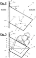
- figure 3 shows a side view of the plant pot holder (1) with an inserted plant pot (21), which protrudes into the trough (9) with a lower section.
- a water filling is present here as an example.
- the water level (S) is here at a higher level in the vertical direction than the lower edge of the plant pot (21) used.
- the plant pot holder (1) is shown in the intended mounting position. It is attached to an object surface (20), which preferably has a vertical orientation.
- the side that is in contact with the surface of the object in the intended attachment position represents the back of the plant pot holder (1).
- the opposite side in the horizontal direction represents the front.
- a longitudinal direction of the plant pot holder extends essentially horizontally along the object surface.
- the longitudinal direction runs essentially parallel to the front edge and rear edges of the top wall (3).
- the plant pot holder (1) has a uniform cross-sectional shape along this longitudinal direction.
- the base body (2) of the plant pot holder (1) comprises an upper wall (3) (wall pointing upwards), a lower wall (4) (wall pointing downwards), a front wall (front intermediate wall (5)) and at least two end walls (6), between which the trough (9) is formed.
- a preferred variant provides that the bottom wall (4) and the front wall (5) are designed to be essentially flat or planar, which enables simple manufacture.
- the lower wall (4) and the front wall (5) can alternatively have a different design. You can particular a uniaxial or have multi-axial curvature or other crowned shape.
- the top wall is preferably flat, at least in the area of the receiving openings (8), so that an annular contact is achieved between a collar on the plant pot (21) and the edge of the receiving opening (8).
- the top wall (4) slopes downwards towards the front and the bottom wall (5) also slopes downwards towards the front. It is therefore an inclined upper wall and an inclined lower wall. Furthermore, according to the example shown, in the fastening position, the front wall (5) slopes downwards towards the rear.
- the angles of inclination (a, b, c) of the top wall, the front wall and/or the bottom wall can be chosen to match an outer contour of the plant pots (21) to be used.
- the angle of inclination can be selected in particular in such a way that essentially uniform distances are achieved between the front wall (5) and a front contour of a plant pot (21) and on the other hand between the lower wall (4) and a bottom contour of the plant pot (21). This is an example in figure 2 shown.
- the inclination of the top wall (3) also has the advantage that any precipitation falling on it (rain, snow, etc.) can run off or slide off towards the front. The precipitation is thus transported away from the object surface (20), which counteracts the formation of moisture damage at the attachment point.
- figure 2 shows a cross-sectional view of the plant pot holder (1) or its base body (2).
- the angles of inclination (a, b, c) of the top wall (3), the bottom wall (4) and the front wall (5) can be selected at will.
- the first angle of inclination (a) of the inclined top wall (4) with respect to a horizontal plane (H) is essentially 30° (angular degrees).
- the first angle of inclination (a) can preferably be between 20° and 50° (angular degrees) relative to a horizontal plane (H).
- the second angle of inclination (b) relative to a horizontal plane (H′) is also essentially 30° (angular degrees) in the examples shown. In other embodiments, it can also preferably be between 20° and 50° (angular degrees) relative to a horizontal plane (H′).
- the first angle of inclination (a) and the second angle of inclination (b) can have essentially the same amount.
- the top wall (3) and the bottom wall (4) can preferably run essentially parallel in the intended fastening position.
- the included angle (belly angle, not marked in the drawings) between the top wall and the front wall is preferably an acute angle.
- the abdominal angle can in particular be between 75° and 90° (angular degrees).
- the angle included between the bottom wall and the front wall is preferably an obtuse angle.
- the ground angle can in particular be between 90° and 115° (angular degrees). Alternatively, other angular amounts are possible.
- figure 2 shows the plant pot holder figure 1 in a cross-sectional view.
- the angles of inclination (a, b, c) of the upper wall (3), the lower wall (4) and the front wall (5) are illustrated again here.
- the inclined front wall (5) preferably has a third angle of inclination (c) to a horizontal plane (H') which is substantially 50° (angular degrees).
- the angle of inclination (c) relative to a horizontal plane (H') can be between 30° and 70° (angular degrees).
- a second strip (15) adjoining essentially vertically upwards (in the fastening position) can be arranged at the rear end of the inclined lower wall (4).
- the second bar (15) can have one or more functions.
- at least one spacer or damper (13) can be arranged on the second strip (15), for example in figure 2 is shown.
- the spacer or damper (13) is preferably attached to the rear-facing surface of the second bar (15).
- a Spacers or dampers (13) can be arranged at a different location or side of the second strip (15) or directly on the rear wall (7).
- a spacer or damper (13) can be dispensed with, which is exemplified in figure 3 is shown.
- the second bar (15) can have any shape and size. According to the preferred embodiment variant in the figures, the second bar (15) ends (in the fastening position) substantially at the level of the front edge (19) between the front wall (5) and the top wall (3), i.e. the height extension of the second bar ( 15) is essentially defined in the fastening position by the height of the front edge (19). Alternatively, a different height profile can be provided.
- the rear wall (7) can be designed in two or more parts and in particular can comprise the first strip (14) and/or the second strip (15).
- the rear wall (7) can be provided between the rear edge of the top wall (3) and the rear edge of the bottom wall (4) at least one bar (15) and also an opening.
- the opening can in particular extend over the entire horizontal length (in the longitudinal direction) of the base body (2). This is advantageous because then the base body (2), which includes the top wall (3), the front wall (5) and the bottom wall (4) and possibly the first and / or the second bar (14, 15), completely in one bending process is producible.
- a rear opening also has advantages for ventilation of the plant pots (21) used in the plant pot holder (1) or the plants and plant substrate contained therein. In particular, the opening prevents a build-up of heat inside the base body, which could otherwise be caused by solar radiation.
- the second bar (15) can form a (partial) delimitation of the trough (9). This case is preferred and shown in the figures.
- the end walls (6) are then preferably connected to the second strip (15), which Figures 2 and 3 is clearly visible.
- the upper edge of the end walls (6) can preferably run at the level of the front edge (19) between the front wall (5) and the top wall (3). Accordingly, it can end essentially flush with the top edge of the second strip (15) on the rear side.
- the front edge (19) between the top wall (3) and the front wall (5), the top edges of the end walls (9) and the top edge of the second strip (15) are provided as the top boundary edges of the trough (9).
- the plant pot holder (1) On the end faces of the base body (2), an area between at least one of the end walls (6) and the upper wall (4) above it can be correspondingly open.
- the plant pot holder (1) preferably has at least one lateral access opening to the trough (9) or to the space enclosed between the top wall, front wall and bottom wall.
- the side opening can advantageously be used to liquid and/or to replenish a fertilizer and/or to act on the above-mentioned moisture-retaining substrate (not shown).
- the at least one side opening promotes air exchange through the interior of the plant pot holder (2). This is particularly advantageous if the plant pot holder (2) is hung outside in the summer and/or is exposed to strong sunlight.
- a wind passing through the side openings can bring about cooling, which is also promoted by the evaporation of liquid from the tub (9) and/or the moisture-storing substrate.
- the wind and/or evaporation-related cooling reduces or prevents premature drying out of the plants used and promotes vegetation.
- the diameter can be, in particular, 10 cm, 11 cm or 12 cm, which is currently the usual collar circumference of plant pots for kitchen herbs and short-lived ornamental plants.
- At least one further opening (17) can be provided in the upper wall (4) (cf. figure 1 ).
- the at least one further opening (17) is preferably considerably smaller than the one or more pot receptacles (8). It can also be used in particular as a pouring opening and/or as a tool holder.
- the plant pot holder (1) can have a water or liquid reservoir (22). This can be of any size and arrangement. According to the example of figure 3 the water reservoir (22) can be arranged one or more times and in particular in an area between the upper wall (3) and the lower wall (4) and to the rear behind at least one pot holder (8).
- the at least one water reservoir (22) can be accessible in particular through one of the further openings (17) mentioned above, in particular in order to fill up and/or clean the water reservoir (22).
- the water reservoir (22) can have a humidification system or irrigation system through which liquid or moisture is released into the tub (9) or the moisture-storing substrate in suitable quantities and at suitable time intervals.
- the delivery can preferably be controllable and/or adjustable.
- separate troughs and/or moistening substrates and/or water reservoirs (22) can be provided for individual pot receptacles (8) and/or groups of pot receptacles (8).
- one or more intermediate walls can be provided, the design and shape of which can be chosen to be the same as or similar to the end walls (6).
- An intermediate wall can be arranged in particular in the longitudinal direction of the plant pot holder (1) between two pot receptacles (8) or between at least one pot receptacle (8) and an adjacent group of pot receptacles (8) or between two adjacent groups of pot receptacles (8).
- a separate water reservoir (22) can be provided for some or all of the tub parts.
- the plant pot holder (1) can include at least one ring-shaped adapter insert (18).
- the adapter insert (18) is preferably provided and adapted to be used in a pot holder (8).
- the outer circumference of the adapter insert (18) can be adapted to the corresponding size of the cup holder (8).
- circular pot receptacles (8) are provided.
- the adapter insert (18) shown has an annular outer circumference.
- the adapter insert (18) can correspondingly have an outer circumference in the shape of a square ring or a circumference in the shape of a rectangular ring.
- the inner circumference of the adapter insert can also be adjusted accordingly to a different cross-sectional contour of a plant pot (21). be adjusted.
- the inner contour can have a round shape, a square shape, a rectangular shape or any other suitable shape.
- the adapter insert (18) can also be used to create a receiving contour that is offset further outwards or inwards than the top wall (3), so that higher or lower plant pots (21) can be used and/or so that the immersion depth of a plant pot (21) in the interior of the plant pot holder (1) and in particular in the tub (9) can be adjustable.
- An overflow opening (10) can be arranged on at least one end wall (6).
- the overflow opening (10) can have any configuration, shape and arrangement.
- the end wall (6) preferably has an upper edge that runs essentially horizontally in the fastening position.
- an overflow opening (10) can be formed by an incision which extends essentially perpendicularly downwards from the upper edge.
- an overflow opening (10) can also be provided in one of the above-mentioned partitions for dividing the tub (9).
- the overflow opening(s) (10) ensure that, for example, rainwater or excess water that has been poured in can drain off in a controlled manner and at a predetermined point.
- water can be distributed into all sections of the trough (9) by introducing water into the trough (9) on one side. It is also avoided that excess water escapes in an uncontrolled manner, for example in the direction of the back, where it could lead to the formation of spots on the object surface (10).
- the plant pot holder (1) and in particular its base (2) can be made of any material.
- a preferred embodiment provides that the top wall, the front wall and the bottom wall and possibly the first and/or second strip (14, 15) are made from a continuous piece of material.
- the base body (2) can preferably be made of a metal, in particular an aluminum sheet. The aluminum sheet can be bent one or more times to form the various wall parts described.
- the end walls (6) can be arranged in any way. They can be connected to at least one edge in one piece with the front wall (5), the bottom wall (6) or the second strip (15). Alternatively, an end wall (6) can be used as a separate wall and attached, for example, by welding. In the examples shown, the end walls (6) are connected by welding to the bottom wall (4), the front wall (5) and possibly the second bar (15).
- the welding tank is preferably designed to be liquid-tight.
- the base body (2) is coated.
- a powder coating and/or a paint finish is particularly suitable for this purpose.
- the coating can serve different purposes. On the one hand, a higher surface load capacity and/or an antibacterial effect can be achieved. The cleanability can also be improved by a coating. On the other hand, the coating can be used to match the color and/or to protect against corrosion.
- the top wall (3), the front wall (5) and the bottom wall (6) are essentially flat.
- At least one of these walls can be crowned. It is also possible, for example, for the front wall (5) and the lower wall (6) to be formed by a plurality of sections which can be connected to one another in an angled or curved manner. Again alternatively, the front wall (5) and the lower wall (6) can be connected, for example, to form a common shell-shaped element, in particular in the form of a semi-cylindrical shell.
- the one or more side openings and/or the rear opening can be omitted.
- the upper edge of the side walls (6) and/or the upper edge of the second strip (15) can be extended upwards to such an extent that they end with the upper wall (3).
- one or more additional covers may be provided to close the side and/or rear opening. This can be indicated, for example, in the winter months in order to better protect the plant pots (21) or the plants contained therein against cold or frost.
- Insulation in particular thermal insulation, can be provided on at least one of the walls (3,4,5,6) mentioned, which in turn can serve as protection against frost or excessive heat in summer.
- the plant pot holder (1) can include one or more attachment adapters so that it can be attached, for example, to a window sill on the outside of the building, a balcony parapet, a railing or a garden fence.
- the at least one fastening adapter is preferably designed for tool-free assembly.
- the plant pot holder (1) can comprise at least one stand, by means of which an object surface (20) is produced according to the examples mentioned above, to which the plant pot holder (1) can be fastened.
- the plant pot holder (1) may be integral with a be connected to such a stand so that it can be set up on the floor or on a tabletop etc.
- two or more pot receptacles (8) and in particular all pot receptacles (8) are arranged in rows on the top wall (3).
- the alignment of the row of pot receptacles is preferably parallel to the longitudinal direction.
- Exactly one row of pot receptacles is preferably provided (cf. figure 1 ).
- two or more rows of cup receptacles can be provided, which in particular can be aligned parallel to one another.
- an arrangement of several pot receptacles in a grid is possible, for example in a square or rectangular grid or in a honeycomb grid.
Description
Die vorliegende Offenbarung betrifft einen Pflanztopfhalter zur Aufnahme eines oder mehrerer Pflanztöpfe.The present disclosure relates to a plant pot holder for holding one or more plant pots.
Pflanzen, insbesondere Küchenkräuter und kleinere Ziergewächse, werden häufig im Handel in einem Pflanztopf angeboten, der eine einfache Ausbildung hat. Der Pflanztopf hat häufig eine im Wesentlichen zylindrische Außenform und besteht aus einem dünnen tiefgezogenen Kunststoffmaterial. Teilweise werden auch Pflanztöpfe mit anderen Grundformen angeboten. Die Pflanztöpfe haben zumeist einen runden Kragen an der Oberkante.Plants, especially kitchen herbs and smaller ornamental plants, are often commercially available in a plant pot that has a simple design. The plant pot often has an essentially cylindrical outer shape and consists of a thin deep-drawn plastic material. In some cases, plant pots with other basic shapes are also available. The plant pots usually have a round collar on the upper edge.
Um eine gekaufte Pflanze in einer ästhetisch ansprechenden Weise anzuordnen, wird der Käufer üblicherweise die Pflanze aus dem Pflanztopf entnehmen und in ein anderes höherwertiges Gefäß umpflanzen. Alternativ kann der Käufer die Pflanze mitsamt des einfachen Kunststoff-Pflanztopfs in einen höherwertigen und ansprechenden Übertopf stellen. Der Übertopf oder das höherwertige Pflanzgefäß werden dann in der Regel auf einer ebenen Fläche abgestellt, im Fall von Küchenkräutern insbesondere auf der Küchenplatte, einem Fensterbrett oder einem Balkon- oder Terrassentisch.In order to arrange a purchased plant in an aesthetically pleasing manner, the purchaser will typically remove the plant from the plant pot and transplant it into another vessel of higher quality. Alternatively, the buyer can place the plant together with the simple plastic plant pot in a higher-quality and attractive cachepot. The cachepot or the higher-quality planter is then usually placed on a flat surface, in the case of kitchen herbs in particular on the kitchen worktop, a window sill or a balcony or terrace table.
Es hat sich gezeigt, dass dieses Vorgehen mit gekauften Pflanzen, insbesondere bei Küchenkräutern und kurzlebigen Ziergewächsen, für die Kunden umständlich und nicht befriedigend ist. Einerseits kauft der Kunde in der Regel nach und nach jeweils unterschiedlich aussehende Übertöpfe, so dass sich ein ästhetisch wenig ansprechendes Sammelsurium bildet und unnötig viel Platz für das Aufstellen der Pflanzen verwendet wird. Andererseits sind im Zuge der immer dichteren Besiedlung in den Städten die Wohnungen und damit auch die Küchen und Küchenarbeitsflächen immer kleiner, so dass oft nur wenig Platz zur Verfügung steht, um verschiedene Küchenkräuter aufzustellen.It has been shown that this procedure with purchased plants, especially with kitchen herbs and short-lived ornamental plants, which is inconvenient and unsatisfactory for customers. On the one hand, the customer usually buys different-looking cachepots one after the other, so that an aesthetically unappealing hodgepodge is formed and an unnecessarily large amount of space is used to set up the plants. On the other hand, in the course of the ever denser settlement in the cities, the apartments and thus also the kitchens and kitchen worktops are getting smaller, so that there is often only little space available to set up different kitchen herbs.
Gleichzeitig steigt aktuell die Wertschätzung der Kunden für frisch zubereitete Nahrungsmittel, in denen direkt von der Pflanze geerntete Blätter, Stängel, Früchte oder sonstige Pflanzenteile verarbeitet werden.At the same time, customers' appreciation of freshly prepared foods in which leaves, stalks, fruits or other plant parts harvested directly from the plant are processed is increasing.
Es besteht somit das Bedürfnis, mit möglichst wenig Zusatzaufwand eine oder mehrere gekaufte Pflanzen, insbesondere Küchen- oder Kräuterpflanzen und kurzlebige Ziergewächse, platzsparend so unterzubringen, dass deren weiteres Wachstum gefördert wird und gleichzeitig ein insgesamt ästhetisch ansprechendes Bild entsteht.There is therefore a need to accommodate one or more purchased plants, in particular kitchen or herb plants and short-lived ornamental plants, with as little additional effort as possible in a space-saving manner so that their further growth is promoted and at the same time an overall aesthetically pleasing picture is created.
Gemäß der vorliegenden Offenbarung wird vorgeschlagen, hierfür einen zweckdienlichen Pflanztopfhalter vorzusehen.According to the present disclosure, it is proposed to provide a suitable plant pot holder for this purpose.
Die bisher bekannten Pflanztopfhalter sind nicht optimal ausgebildet. Beispielsweise ist aus der
Verschiedene Varianten von Übertöpfen und Manschetten zur Aufnahme jeweils eines einzelnen Pflanztopfs und zur Herstellung eines ansprechenderen Erscheinungsbilds sind beispielsweise bekannt aus
Aus
Aus
Es ist Aufgabe der vorliegenden Erfindung, einen verbesserten Pflanztopfhalter aufzuzeigen, der mindestens eines der oben genannten Kundenbedürfnisse in besserer Weise erfüllt.It is an object of the present invention to provide an improved plant pot holder that better meets at least one of the above customer needs.
Die Erfindung löst diese Aufgabe durch die Merkmale des Hauptanspruchs.The invention solves this problem with the features of the main claim.
Der Pflanztopfhalter gemäß der vorliegenden Offenbarung ist zur Aufnahme eines oder bevorzugt mehrerer Pflanztöpfe ausgebildet.The plant pot holder according to the present disclosure is designed to hold one or preferably several plant pots.
Der Pflanztopfhalter hat einen Grundkörper, der im Bereich einer rückseitigen Wandung an einer im Wesentlichen senkrechten Objektfläche befestigbar ist. Der Grundkörper braucht also nicht auf einer ebenen bzw. waagrechten Fläche abgestellt zu werden. Es ist vielmehr möglich, ihn beispielsweise in der Küche an einer freien Wandfläche, oder beispielsweise auf dem Balkon an einer Brüstung oder einem Geländer, oder an einer Seitenwand eines Gebäudes oder eines Möbelstücks zu befestigen.The plant pot holder has a base body that can be fastened to a substantially vertical object surface in the area of a rear wall. The base body therefore does not need to be placed on a flat or horizontal surface. Rather, it is possible to attach it, for example, to a free wall surface in the kitchen, or, for example, to a parapet or railing on the balcony, or to a side wall of a building or a piece of furniture.
Gemäß einer bevorzugten Ausführungsvariante ist der Pflanztopfhalter dazu ausgebildet und vorgesehen, an einem außen liegenden Fensterbrett befestigt zu werden. So kann ein Kunde den Pflanztopfhalter insbesondere außenseitig an seinem Küchenfenster platzieren. In dem Pflanztopfhalter können dann Kräuterpflanzen oder andere Küchenpflanzen mitsamt des gekauft Pflanztopfes eingesetzt werden und befinden sich damit jederzeit im direkten Zugriff.According to a preferred embodiment variant, the plant pot holder is designed and intended to be attached to an external window sill. A customer can place the plant pot holder in particular on the outside of his kitchen window. Herbs or other kitchen plants can then be used in the plant pot holder together with the purchased plant pot and are therefore always directly accessible.
Der Grundkörper hat eine einheitliche Querschnittsform mit einer in der vorgesehenen Befestigungsposition nach oben weisenden Wandung (nachfolgend als Oberwand bezeichnet), einer in der Befestigungsposition nach unten weisenden Wandung (nachfolgend als Unterwand bezeichnet) sowie einer vorderseitigen Zwischenwandung (nachfolgend als Vorderwand bezeichnet). Die Vorderwand erstreckt sich zwischen der Oberwand und der Unterwand. Die Oberwand und die Unterwand können jeweils ein vorderseitiges Ende aufweisen, wobei sich die Vorderwand bevorzugt zwischen diesen Enden erstreckt.The base body has a uniform cross-sectional shape with a wall pointing upwards in the intended fastening position (hereinafter referred to as the upper wall), a wall pointing downwards in the fastening position (hereinafter referred to as the lower wall) and a front intermediate wall (hereinafter referred to as the front wall). The front wall extends between the top wall and the bottom wall. The top wall and the bottom wall may each have a front end, preferably with the front wall extending between those ends.
Oberwand, Vorderwand und Unterwand sind einstückig miteinander verbunden.The top wall, front wall and bottom wall are connected to one another in one piece.
Die Oberwand ist zur Vorderseite hin nach unten geneigt. In der geneigten Oberwand sind eine, zwei oder mehr Öffnungen vorgesehen, die jeweils eine Topfaufnahme für einen Pflanztopf bilden. Für jeden Pflanztopf kann eine separate Topfaufnahme vorgesehen sein. Alternativ kann eine Topfaufnahme für die Aufnahme von zwei oder mehr Pflanztöpfen, insbesondere für eine Gruppe von Pflanztöpfen vorgesehen sein.The top wall slopes downward toward the front. One, two or more openings are provided in the inclined top wall, each of which forms a pot receptacle for a plant pot. One can be used for each plant pot separate pot holder can be provided. Alternatively, a pot holder for holding two or more plant pots, in particular for a group of plant pots, can be provided.
Die in der Befestigungsposition geneigte Anordnung der Oberwand hat verschiedene Vorteile. Zum einen wird die Oberseite des Pflanztopfs zur Vorderseite, d.h. zum Kunden / Nutzer hin geneigt, so dass die Pflanze besser sichtbar und damit ästhetisch ansprechender präsentiert ist. Andererseits wird die Zugänglichkeit zur Pflanze verbessert, was insbesondere für das schnelle Abernten von Blättern, Stängeln, Blüten, Wurzeln oder sonstigen Pflanzenteilen hilfreich ist.The inclined arrangement of the top wall in the fastening position has several advantages. On the one hand, the top of the plant pot is tilted towards the front, i.e. towards the customer / user, so that the plant is more visible and therefore presented in a more aesthetically pleasing way. On the other hand, accessibility to the plant is improved, which is particularly helpful for quickly harvesting leaves, stems, flowers, roots or other plant parts.
Durch die Unterwand und die Vorderwand wird ein eingesetzter Pflanztopf nach unten hin umschlossen. Etwaig an der Unterseite des Pflanztopfes herauswachsende Wurzeln oder abtropfendes Wasser sind somit durch die Unterwand sowie die Vorderwand abgeschirmt. Dadurch wird einerseits ein sauberes Gesamterscheinungsbild erzeugt und andererseits verhindert, dass Flüssigkeiten oder Pflanzenteile unkontrolliert in die Umgebung abgegeben werden und beispielsweise Flecken verursachen.An inserted plant pot is enclosed at the bottom by the lower wall and the front wall. Any roots growing out on the underside of the plant pot or dripping water are thus shielded by the bottom wall and the front wall. On the one hand, this creates a clean overall appearance and, on the other hand, prevents liquids or plant parts from being released into the environment in an uncontrolled manner and causing stains, for example.
Erfindungsgemäß ist auch die Unterwand zur Vorderseite hin nach unten geneigt. Ferner sind an den Stirnenden des Grundkörpers (d.h. an den in Längsrichtung außen liegende Enden) zwischen der geneigten Unterwand und der Vorderwand Stirnwände angeordnet. Die Stirnwände verlaufen bevorzugt im Wesentlichen quer zur Unterwand und zur Vorderwand und somit in der Befestigungsposition im Wesentlichen senkrecht. Alternativ kann ein schräger Verlauf vorgesehen sein. Zwischen den Stirnwänden, der geneigten Unterwand und der Vorderwand wird somit eine Wanne gebildet. Mit anderen Worten sind die Vorderwand, die Unterwand sowie die Stirnwände derart angeordnet und miteinander verbunden, dass sie in der vorgesehenen Befestigungsposition eine flüssigkeitsdichte Wanne bilden, insbesondere eine nach unten und zur Seite hin flüssigkeitsdichte Wanne.According to the invention, the bottom wall is also inclined downwards towards the front. Furthermore, end walls are arranged at the end ends of the main body (ie, at the outer ends in the longitudinal direction) between the inclined bottom wall and the front wall. The end walls preferably run essentially transversely to the bottom wall and to the front wall thus essentially vertical in the fastening position. Alternatively, an inclined course can be provided. A trough is thus formed between the end walls, the inclined lower wall and the front wall. In other words, the front wall, the bottom wall and the end walls are arranged and connected to one another in such a way that they form a liquid-tight trough in the intended attachment position, in particular a liquid-tight trough at the bottom and to the side.
Ein eingesetzter Pflanztopf ragt bevorzugt zumindest teilweise in diese Wanne hinein. Die Wanne kann mit Wasser und etwaig einem Düngezusatz befüllt werden. In der vorgesehenen Befestigungsposition ragt ein Pflanztopf, der in den Pflanztopfhalter eingesetzt ist, bevorzugt (nur) mit einem unteren Abschnitt in die Wanne hinein. Die in dem Pflanztopf befindliche Pflanze oder das umgebende Pflanzsubstrat kann somit ein Stück weit in das in der Wanne enthaltene Wasser eintauchen, so dass die in einem Pflanztopf enthaltene Pflanze auf einfache Weise mit Wasser und Nährstoffen versorgt wird.An inserted plant pot preferably protrudes at least partially into this trough. The tub can be filled with water and possibly a fertilizer additive. In the intended fastening position, a plant pot that is inserted into the plant pot holder preferably protrudes (only) with a lower section into the tub. The plant located in the plant pot or the surrounding plant substrate can thus dip a little into the water contained in the tub, so that the plant contained in a plant pot is supplied with water and nutrients in a simple manner.
Die Wanne kann teilweise oder vollständig mit einem Befeuchtungs-Substrat befüllt sein, beispielsweise mit einem saugfähigen Schwamm, Blähton, einem wasserspeichernden Granulat oder einem in sonstiger Weise geeigneten flüssigkeitsspeichernden Material. Die Wanne kann in einer solchen Weise befüllt sein, dass ein ausreichender Kontakt zwischen einerseits dem Pflanztopf bzw. dem darin enthaltenen Pflanzsubstrat (Erde) oder der Pflanze und andererseits dem Befeuchtungs-Substrat gewährleistet wird.The trough can be partially or completely filled with a moistening substrate, for example with an absorbent sponge, expanded clay, water-storing granules or some other suitable liquid-storing material. The tub can be filled in such a way that sufficient contact between the one hand, the plant pot or the plant substrate contained therein (soil) or the Plant and on the other hand the humidification substrate is guaranteed.
Die Vorderwand des Pflanztopfhalters kann bevorzugt zur Rückseite hin nach unten geneigt sein. Hierdurch wird ein schlanker und platzsparender Aufbau erreicht.The front wall of the plant pot holder can preferably be inclined downwards towards the rear. This achieves a slim and space-saving structure.
Der Pflanztopfhalter kann auf beliebige Weise befestigt werden. Bevorzugt ist am rückseitigen Ende der Oberwand eine geeignete Befestigungsstruktur angeordnet, beispielsweise eine Schraubenaufnahme. Eine Befestigungsstruktur kann auch ein einteiliges oder mehrteiliges Fixiermittel umfassen, mit dem es beispielsweise an einem Fensterbrett, einer Fensterlaibung, einem Geländer oder einer Brüstung fixierbar ist.The plant pot holder can be attached in any way. A suitable fastening structure, for example a screw receptacle, is preferably arranged at the rear end of the top wall. A fastening structure can also include a one-piece or multi-piece fixing means, with which it can be fixed, for example, to a window sill, a window reveal, a railing or a parapet.
Bevorzugt ist am rückseitigen Ende der geneigten Oberwand eine im Wesentlichen vertikal nach oben anschließende erste Leiste angeordnet. Die erste Leiste kann ein Bestandteil des Grundkörpers sein. Die Befestigungsstruktur kann bevorzugt an oder in dieser ersten Leiste untergebracht sein.Preferably, a first bar which connects essentially vertically upwards is arranged at the rear end of the inclined upper wall. The first bar can be part of the base body. The fastening structure can preferably be accommodated on or in this first bar.
Weitere vorteilhafte Ausbildungen der Erfindung sind in den Unteransprüchen, der nachfolgenden Beschreibung sowie den beigefügten Zeichnungen angegeben.Further advantageous developments of the invention are specified in the dependent claims, the following description and the accompanying drawings.
Die Erfindung ist in den Zeichnungen beispielhaft und schematisch dargestellt. Diese zeigen:
- Figur 1:
- eine beispielhafte Ausführung des Pflanztopfhalters gemäß der vorliegenden Offenbarung in der Befestigungsposition;
- Figur 2:
- eine Querschnittsdarstellung des Pflanztopfhalters aus
Figur 1 gemäß Schnittlinie II-II; - Figur 3:
- eine seitliche Außenansicht eines Pflanztopfhalters gemäß einer zweiten Ausführungsvariante und mit einem eingesetzten Pflanztopf.
- Figure 1:
- an exemplary embodiment of the plant pot holder according to the present disclosure in the mounting position;
- Figure 2:
- a cross-sectional view of the plant pot holder
figure 1 according to section line II-II; - Figure 3:
- a lateral external view of a plant pot holder according to a second embodiment and with a plant pot used.
Eine bevorzugte Ausführungsvariante des Pflanztopfhalters gemäß der vorliegenden Offenbarung ist in
In den Figuren ist der Pflanztopfhalter (1) in der vorgesehenen Befestigungsposition dargestellt. Dabei ist er an einer Objektfläche (20) befestigt, die bevorzugt eine senkrechte Ausrichtung hat. Diejenige Seite, die in der vorgesehenen Befestigungsposition an der Objektfläche anliegt, stellt die Rückseite des Pflanztopfhalters (1) dar. Die in Horizontalrichtung entgegengesetzte Seite stellt die Vorderseite dar.In the figures, the plant pot holder (1) is shown in the intended mounting position. It is attached to an object surface (20), which preferably has a vertical orientation. The side that is in contact with the surface of the object in the intended attachment position represents the back of the plant pot holder (1). The opposite side in the horizontal direction represents the front.
Eine Längsrichtung des Pflanztopfhalters erstreckt sich in der vorgesehenen Befestigungsposition im Wesentlichen horizontal entlang der Objektfläche. Die Längsrichtung verläuft in der Befestigungsposition im Wesentlichen parallel zur Vorderkante und rückwärtigen Katen der Oberwand (3). Entlang dieser Längsrichtung hat der Pflanztopfhalter (1) eine einheitliche Querschnittsform.In the intended fastening position, a longitudinal direction of the plant pot holder extends essentially horizontally along the object surface. In the fastening position, the longitudinal direction runs essentially parallel to the front edge and rear edges of the top wall (3). The plant pot holder (1) has a uniform cross-sectional shape along this longitudinal direction.
Der Grundkörper (2) des Pflanztopfhalters (1) umfasst eine Oberwand (3) (nach oben weisende Wandung), eine Unterwand (4) (nach unten weisende Wandung), eine Vorderwand (vorderseitige Zwischenwandung (5)) sowie mind. zwei endseitige Stirnwände (6), zwischen denen die Wanne (9) gebildet ist. Eine bevorzugte Variante sieht vor, dass die Unterwand (4) und die Vorderwand (5) im Wesentlichen flach oder eben ausgebildet sind, was eine einfache Herstellung ermöglicht. Die Unterwand (4) und die Vorderwand (5) können alternativ eine andere Ausbildung haben. Sie können insbesondere eine einachsige oder mehrachsige Krümmung oder sonstige ballige Form haben. Die Oberwand ist bevorzugt zumindest im Bereich der Aufnahmeöffnungen (8) flach ausgebildet, sodass eine ringförmige Anlage zwischen einem Kragen am Pflanztopf (21) und dem Rand der Aufnahmeöffnung (8) erzielt wird.The base body (2) of the plant pot holder (1) comprises an upper wall (3) (wall pointing upwards), a lower wall (4) (wall pointing downwards), a front wall (front intermediate wall (5)) and at least two end walls (6), between which the trough (9) is formed. A preferred variant provides that the bottom wall (4) and the front wall (5) are designed to be essentially flat or planar, which enables simple manufacture. The lower wall (4) and the front wall (5) can alternatively have a different design. You can particular a uniaxial or have multi-axial curvature or other crowned shape. The top wall is preferably flat, at least in the area of the receiving openings (8), so that an annular contact is achieved between a collar on the plant pot (21) and the edge of the receiving opening (8).
In dem gezeigten Beispiel ist die Oberwand (4) zur Vorderseite hin nach unten geneigt und es ist ebenfalls die Unterwand (5) zur Vorderseite hin nach unten geneigt. Es handelt sich somit um eine geneigte Oberwand sowie eine geneigte Unterwand. Darüber hinaus ist gemäß dem gezeigten Beispiel in der Befestigungsposition die Vorderwand (5) zur Rückseite hin nach unten geneigt.In the example shown, the top wall (4) slopes downwards towards the front and the bottom wall (5) also slopes downwards towards the front. It is therefore an inclined upper wall and an inclined lower wall. Furthermore, according to the example shown, in the fastening position, the front wall (5) slopes downwards towards the rear.
Wenn der Pflanztopfhalter wie in dem dargestellten Beispiel in etwa auf Hüfthöhe an einer Wand aufgehängt wird, wird durch die zur Rückseite hin nach unten geneigte Vorderwand (5) zusätzliche Beinfreiheit gewährt.If the plant pot holder is hung on a wall at about hip height, as in the example shown, additional legroom is provided by the front wall (5) sloping downwards towards the back.
Die Neigungswinkel (a, b, c) der Oberwand, der Vorderwand und/oder der Unterwand können in Anpassung an eine Außenkontur der zu verwendenden Pflanztöpfe (21) gewählt sein. Die Wahl der Neigungswinkel kann insbesondere derart erfolgen, dass im Wesentlichen einheitliche Abstände zwischen der Vorderwand (5) und ein vorderseitigen Kontur eines Pflanztopfs (21) und andererseits zwischen der Unterwand (4) und einer Bodenkontur des Pflanztopfs (21) erzielt wird. Dies ist beispielhaft in
Wenn der Pflanztopfhalter (1) im Freien befestigt wird, hat die Neigung der Oberwand (3) auch den Vorteil, dass etwaig darauf fallender Niederschlag (Regen, Schnee etc.) zur Vorderseite hin ablaufen bzw. abrutschen kann. Der Niederschlag wird also von der Objektfläche (20) weg transportiert, was der Bildung von Nässeschäden an der Befestigungsstelle entgegenwirkt.If the plant pot holder (1) is attached outdoors, the inclination of the top wall (3) also has the advantage that any precipitation falling on it (rain, snow, etc.) can run off or slide off towards the front. The precipitation is thus transported away from the object surface (20), which counteracts the formation of moisture damage at the attachment point.
Der zweite Neigungswinkel (b) gegenüber einer Horizontalebene (H') beträgt in den gezeigten Beispielen ebenfalls im Wesentlichen 30° (Winkelgrad). Er kann bevorzugt in anderen Ausführungen ebenfalls zwischen 20° und 50° (Winkelgrad) gegenüber einer Horizontalebene (H') betragen.The second angle of inclination (b) relative to a horizontal plane (H′) is also essentially 30° (angular degrees) in the examples shown. In other embodiments, it can also preferably be between 20° and 50° (angular degrees) relative to a horizontal plane (H′).
Besonders bevorzugt können der erste Neigungswinkel (a) und der zweite Neigungswinkel (b) im Wesentlichen den gleichen Betrag haben. Anders ausgedrückt können die Oberwand (3) und die Unterwand (4) in der vorgesehenen Befestigungsposition bevorzugt im Wesentlichen parallel verlaufen.Particularly preferably, the first angle of inclination (a) and the second angle of inclination (b) can have essentially the same amount. In other words, the top wall (3) and the bottom wall (4) can preferably run essentially parallel in the intended fastening position.
Der zwischen der Oberwand und der Vorderwand eingeschlossene Winkel (Bauchwinkel, in den Zeichnungen nicht gekennzeichnet) ist bevorzugt ein spitzer Winkel. Der Bauchwinkel kann insbesondere zwischen 75° und 90° (Winkelgrad) betragen. Der zwischen der Unterwand und der Vorderwand eingeschlossene Winkel (Bodenwinkel, in den Zeichnungen nicht gekennzeichnet) ist bevorzugt ein stumpfer Winkel. Der Bodenwinkel kann insbesondere zwischen 90° und 115° (Winkelgrad) betragen. Alternativ sind andere Winkelbeträge möglich.The included angle (belly angle, not marked in the drawings) between the top wall and the front wall is preferably an acute angle. The abdominal angle can in particular be between 75° and 90° (angular degrees). The angle included between the bottom wall and the front wall (floor angle, not marked in the drawings) is preferably an obtuse angle. The ground angle can in particular be between 90° and 115° (angular degrees). Alternatively, other angular amounts are possible.
Am rückseitigen Ende der geneigten Unterwand (4) kann gemäß einer bevorzugten Ausführung eine (in der Befestigungsposition) im Wesentlichen vertikal nach oben anschließende zweite Leiste (15) angeordnet sein. Die zweite Leiste (15) kann eine oder mehrere Funktionen haben. Beispielsweise kann an der zweiten Leiste (15) mind. ein Abstandhalter oder Dämpfer (13) angeordnet sein, der beispielhaft in
Die zweite Leiste (15) kann eine beliebige Form und Größe haben. Gemäß der bevorzugten Ausführungsvariante in den Figuren endet die zweite Leiste (15) (in der Befestigungsposition) im Wesentlichen auf dem Höhenniveau der vorderseitigen Kante (19) zwischen der Vorderwand (5) und der Oberwand (3), d.h. die Höhenerstreckung der zweiten Leiste (15) ist in der Befestigungsposition im Wesentlichen durch die Höhe der vorderseitigen Kante (19) festgelegt. Alternativ kann ein anderer Höhenverlauf vorgesehen sein.The second bar (15) can have any shape and size. According to the preferred embodiment variant in the figures, the second bar (15) ends (in the fastening position) substantially at the level of the front edge (19) between the front wall (5) and the top wall (3), i.e. the height extension of the second bar ( 15) is essentially defined in the fastening position by the height of the front edge (19). Alternatively, a different height profile can be provided.
Wie sich aus den Figuren ergibt, kann die rückseitige Wandung (7) zwei- oder mehrteilig ausgebildet sein und insbesondere die erste Leiste (14) und/oder die zweite Leiste (15) umfassen. Mit anderen Worten kann die rückseitige Wandung (7) zwischen der rückseitigen Kante der Oberwand (3) und der rückseitigen Kante der Unterwand (4) mindestens eine Leiste (15) und weiterhin eine Öffnung vorgesehen sein. Die Öffnung kann sich insbesondere über die gesamte horizontale Länge (in Längsrichtung) des Grundkörpers (2) erstrecken kann. Dies ist vorteilhaft, weil dann der Grundkörper (2), der die Oberwand (3), die Vorderwand (5) und die Unterwand (4) sowie etwaig die erste und/oder die zweite Leiste (14, 15) umfasst, vollständig in einem Biegeverfahren herstellbar ist. Eine rückseitige Öffnung hat ferner Vorteile für eine Belüftung der in den Pflanztopfhalter (1) eingesetzten Pflanztöpfe (21) bzw. enthaltene Pflanzen und Pflanzsubstrat. Die Öffnung beugt insbesondere einem Hitzestau innerhalb des Grundkörpers vor, der sonst etwaig durch Sonneneinstrahlung hervorgerufen werden könnte.As can be seen from the figures, the rear wall (7) can be designed in two or more parts and in particular can comprise the first strip (14) and/or the second strip (15). In other words, the rear wall (7) can be provided between the rear edge of the top wall (3) and the rear edge of the bottom wall (4) at least one bar (15) and also an opening. The opening can in particular extend over the entire horizontal length (in the longitudinal direction) of the base body (2). This is advantageous because then the base body (2), which includes the top wall (3), the front wall (5) and the bottom wall (4) and possibly the first and / or the second bar (14, 15), completely in one bending process is producible. A rear opening also has advantages for ventilation of the plant pots (21) used in the plant pot holder (1) or the plants and plant substrate contained therein. In particular, the opening prevents a build-up of heat inside the base body, which could otherwise be caused by solar radiation.
Die zweite Leiste (15) kann eine (Teil-) Begrenzung der Wanne (9) bilden. Dieser Fall ist bevorzugt und in den Figuren gezeigt. Die Stirnwände (6) sind dann bevorzugt mit der zweiten Leiste (15) verbunden, was in
An den Stirnseiten des Grundkörpers (2) kann ein Bereich zwischen mind. einer der Stirnwände (6) und der darüber liegenden Oberwand (4) entsprechend geöffnet sein. Mit anderen Worten weist der Pflanztopfhalter (1) bevorzugt mind. eine seitliche Zugangsöffnung zur Wanne (9) bzw. zu dem zwischen Oberwand, Vorderwand und Unterwand eingeschlossenen Raum auf. Die seitliche Öffnung kann vorteilhafter Weise dazu genutzt werden, Flüssigkeit und/oder ein Düngemittel nachzufüllen und/oder auf das oben erwähnte feuchtigkeitsspeichernde Substrat (nicht dargestellt) einzuwirken.On the end faces of the base body (2), an area between at least one of the end walls (6) and the upper wall (4) above it can be correspondingly open. In other words, the plant pot holder (1) preferably has at least one lateral access opening to the trough (9) or to the space enclosed between the top wall, front wall and bottom wall. The side opening can advantageously be used to liquid and/or to replenish a fertilizer and/or to act on the above-mentioned moisture-retaining substrate (not shown).
Die mind. eine seitliche Öffnung begünstigt einen Luftaustausch durch den Innenraum des Pflanztopfhalters (2). Dies ist insbesondere dann vorteilhaft, wenn der Pflanztopfhalter (2) im Sommer im Außenbereich aufgehängt ist und/oder starker Sonneneinstrahlung ausgesetzt ist. Ein durch die seitlichen Öffnungen durchtretender Wind kann eine Kühlung herbeiführen, die auch durch das Verdunsten von Flüssigkeit aus der Wanne (9) und/oder dem feuchtigkeitsspeichernden Substrat begünstigt wird. Die wind- und/oder verdunstungsbedingte Kühlung vermindert oder verhindert ein vorzeitiges Austrocken der eingesetzten Pflanzen und fördert die Vegetation.The at least one side opening promotes air exchange through the interior of the plant pot holder (2). This is particularly advantageous if the plant pot holder (2) is hung outside in the summer and/or is exposed to strong sunlight. A wind passing through the side openings can bring about cooling, which is also promoted by the evaporation of liquid from the tub (9) and/or the moisture-storing substrate. The wind and/or evaporation-related cooling reduces or prevents premature drying out of the plants used and promotes vegetation.
Die eine oder mehreren Topfaufnahmen (8) können eine beliebige Anordnung, Ausbildung und Größe haben. Bevorzugt sind in Längsrichtung des Pflanztopfhalters (1) zwei oder mehr Topfaufnahmen hintereinander angeordnet. Die Topfaufnahmen (8) können gleich oder unterschiedlich geformt und angeordnet sein. Die mind. eine Topfaufnahme (8) und insbesondere alle Topfaufnahmen (8) können je nach Einsatzzweck
- eine runde Form haben, oder
- eine quadratische Form haben, oder
- eine rechteckige Form haben.
- have a round shape, or
- have a square shape, or
- have a rectangular shape.
Als besonders günstig hat es sich erwiesen, alle Topfaufnahmen (8) mit einer runden Grundform vorzusehen, wobei die Topfaufnahmen (8) einen einheitlichen Durchmesser haben. Der Durchmesser kann insbesondere 10 cm, 11 cm oder 12 cm betragen, was derzeit in der Praxis übliche Kragenumfänge von Pflanztöpfen für Küchenkräuter und kurzlebige Zierpflanzen sind.It has proven to be particularly favorable to provide all pot holders (8) with a round basic shape, wherein the pot receptacles (8) have a uniform diameter. The diameter can be, in particular, 10 cm, 11 cm or 12 cm, which is currently the usual collar circumference of plant pots for kitchen herbs and short-lived ornamental plants.
Gemäß einer weiteren bevorzugten Variante kann in der Oberwand (4) mind. eine weitere Öffnung (17) vorgesehen sein (vgl.
Der Pflanztopfhalter (1) kann einen Wasser- oder Flüssigkeitsspeicher (22) aufweisen. Dieser kann eine beliebige Größe und Anordnung haben. Gemäß dem Beispiel von
Gemäß einer bevorzugten Ausführungsvariante können für einzelne Topfaufnahmen (8) und/oder Gruppen von Topfaufnahmen (8) jeweils separate Wannen und/oder Befeuchtungs-Substrate und/oder Wasserspeicher (22) vorgesehen sein. Dementsprechend können bedarfsweise eine oder mehrere Zwischenwände vorgesehen sein, deren Ausbildung und Form insbesondere gleich oder ähnlich zu den Stirnwänden (6) gewählt sein kann. Eine Zwischenwand kann insbesondere in Längsrichtung des Pflanztopfhalters (1) zwischen zwei Topfaufnahmen (8) bzw. zwischen mind. einer Topfaufnahme (8) und einer benachbarten Gruppe von Topfaufnahmen (8) bzw. zwischen zwei benachbarten Gruppen von Topfaufnahmen (8) angeordnet sein.According to a preferred embodiment variant, separate troughs and/or moistening substrates and/or water reservoirs (22) can be provided for individual pot receptacles (8) and/or groups of pot receptacles (8). Accordingly, if required, one or more intermediate walls can be provided, the design and shape of which can be chosen to be the same as or similar to the end walls (6). An intermediate wall can be arranged in particular in the longitudinal direction of the plant pot holder (1) between two pot receptacles (8) or between at least one pot receptacle (8) and an adjacent group of pot receptacles (8) or between two adjacent groups of pot receptacles (8).
Für einige oder alle Wannenteile kann ein jeweils separater Wasserspeicher (22) vorgesehen sein.A separate water reservoir (22) can be provided for some or all of the tub parts.
Wie in
Durch den Adaptereinsatz (18) kann auch eine gegenüber der Oberwand (3) weiter nach außen oder nach innen versetzte Aufnahmekontur geschaffen werden, so dass höhere oder niedrigere Pflanztöpfe (21) verwendet werden können und/oder so dass die Eintauchtiefe eines Pflanztopfs (21) in den Innenraum des Pflanztopfhalters (1) und insbesondere in die Wanne (9) einstellbar sein kann.The adapter insert (18) can also be used to create a receiving contour that is offset further outwards or inwards than the top wall (3), so that higher or lower plant pots (21) can be used and/or so that the immersion depth of a plant pot (21) in the interior of the plant pot holder (1) and in particular in the tub (9) can be adjustable.
An mind. einer Stirnwand (6) kann eine Überlauföffnung (10) angeordnet sein. Die Überlauföffnung (10) kann eine beliebige Ausbildung, Form und Anordnung haben. Bevorzugt weist die Stirnwand (6) eine in der Befestigungsposition im Wesentlichen horizontal verlaufende Oberkante auf. In diesem Fall kann eine Überlauföffnung (10) durch einen Einschnitt gebildet sein, der sich von der Oberkante her im Wesentlichen senkrecht nach unten erstreckt.An overflow opening (10) can be arranged on at least one end wall (6). The overflow opening (10) can have any configuration, shape and arrangement. The end wall (6) preferably has an upper edge that runs essentially horizontally in the fastening position. In this case, an overflow opening (10) can be formed by an incision which extends essentially perpendicularly downwards from the upper edge.
Mind. eine Überlauföffnung (10) kann ebenso in einer der oben erwähnten Zwischenwände zur Unterteilung der Wanne (9) vorgesehen sein.min. an overflow opening (10) can also be provided in one of the above-mentioned partitions for dividing the tub (9).
Durch die Überlauföffnung(en) (10) wird erreicht, dass beispielsweise durch Regenwasser oder durch über Gießen eingebrachtes überschüssiges Wasser in kontrollierter Weise und an einer vorgegebenen Stelle abläuft.The overflow opening(s) (10) ensure that, for example, rainwater or excess water that has been poured in can drain off in a controlled manner and at a predetermined point.
Ferner kann durch eine oder mehrere Überlauföffnungen in den Zwischenwänden erreicht werden, dass durch das einseitige Einbringen von Wasser in die Wanne (9) eine Verteilung bis in alle Teilabschnitte der Wanne (9) erreicht wird. Es wird weiterhin vermieden, dass überschüssiges Wasser unkontrolliert beispielsweise in Richtung der Rückseite austritt, wo es zu einer Fleckenbildung an der Objektfläche (10) führen könnte.Furthermore, by means of one or more overflow openings in the partition walls, water can be distributed into all sections of the trough (9) by introducing water into the trough (9) on one side. It is also avoided that excess water escapes in an uncontrolled manner, for example in the direction of the back, where it could lead to the formation of spots on the object surface (10).
Der Pflanztopfhalter (1) und insbesondere dessen Grundkörper (2) können aus einem beliebigen Material gefertigt sein. Eine bevorzugte Ausführung sieht vor, dass die Oberwand, die Vorderwand und die Unterwand sowie etwaig die erste und/oder zweite Leiste (14,15) aus einem durchgehenden Materialstück gefertigt sind. Weiterhin kann der Grundkörper (2) bevorzugt aus einem Metall gefertigt sein, insbesondere aus einem Aluminiumblech. Das Aluminiumblech kann ein oder mehrmals gebogen werden, um die verschiedenen beschriebenen Wandungsteile zu bilden.The plant pot holder (1) and in particular its base (2) can be made of any material. A preferred embodiment provides that the top wall, the front wall and the bottom wall and possibly the first and/or second strip (14, 15) are made from a continuous piece of material. Furthermore, the base body (2) can preferably be made of a metal, in particular an aluminum sheet. The aluminum sheet can be bent one or more times to form the various wall parts described.
Die Stirnwände (6) können auf beliebige Weise angeordnet sein. Sie können an zumindest einer Kante einstückig mit der Vorderwand (5) der Unterwand (6) oder der zweiten Leiste (15) verbunden sein. Alternativ kann eine Stirnwand (6) als separate Wandung eingesetzt und beispielsweise durch Schweißen angebunden sein. In den gezeigten Beispielen sind die Stirnwände (6) durch Schweißen mit der Unterwand (4), der Vorderwand (5) und etwaig der zweiten Leiste (15) verbunden. Die Schweißwanne ist bevorzugt flüssigkeitsdicht ausgeführt.The end walls (6) can be arranged in any way. They can be connected to at least one edge in one piece with the front wall (5), the bottom wall (6) or the second strip (15). Alternatively, an end wall (6) can be used as a separate wall and attached, for example, by welding. In the examples shown, the end walls (6) are connected by welding to the bottom wall (4), the front wall (5) and possibly the second bar (15). The welding tank is preferably designed to be liquid-tight.
Gemäß einer weiteren bevorzugten Ausbildung ist der Grundkörper (2) beschichtet. Hierfür kommt insbesondere eine Pulverbeschichtung und/oder eine Lackierung in Frage. Die Beschichtung kann verschiedenen Zwecken dienen. Einerseits kann eine höhere Oberflächenbelastbarkeit und/oder eine antibakterielle Wirkung erreicht werden. Auch die Reinigbarkeit kann durch eine Beschichtung verbessert sein. Andererseits kann durch die Beschichtung eine farbliche Anpassung und/oder ein Korrosionsschutz erreicht werden.According to a further preferred embodiment, the base body (2) is coated. A powder coating and/or a paint finish is particularly suitable for this purpose. The coating can serve different purposes. On the one hand, a higher surface load capacity and/or an antibacterial effect can be achieved. The cleanability can also be improved by a coating. On the other hand, the coating can be used to match the color and/or to protect against corrosion.
Abwandlungen der Erfindung sind in verschiedener Weise möglich. Insbesondere können die zu den Ausführungsbeispielen gezeigten, beschriebenen oder beanspruchten Merkmale in beliebiger Weise miteinander kombiniert oder untereinander ersetzt werden.Various modifications of the invention are possible. In particular, the features shown, described or claimed for the exemplary embodiments can be combined with one another or replaced with one another in any desired manner.
In den gezeigten Beispielen sind die Oberwand (3), die Vorderwand (5) und die Unterwand (6) im Wesentlichen flach bzw. eben ausgebildet.In the examples shown, the top wall (3), the front wall (5) and the bottom wall (6) are essentially flat.
Alternativ kann mindestens eine dieser Wandungen ballig ausgeformt sein. Ferner ist es möglich, dass beispielsweise die Vorderwand (5) und die Unterwand (6) durch mehrere Teilstücke gebildet sind, die insbesondere untereinander abgewinkelt oder gekrümmt verbunden sein können. Wiederum alternativ können die Vorderwand (5) und die Unterwand (6) beispielsweise zu einem gemeinsamen schalenförmigen Element verbunden sein, insbesondere in Form einer Halbzylinderschale.Alternatively, at least one of these walls can be crowned. It is also possible, for example, for the front wall (5) and the lower wall (6) to be formed by a plurality of sections which can be connected to one another in an angled or curved manner. Again alternatively, the front wall (5) and the lower wall (6) can be connected, for example, to form a common shell-shaped element, in particular in the form of a semi-cylindrical shell.
Auf die ein oder mehreren seitlichen Öffnungen und/oder auf die rückseitige Öffnung kann verzichtet werden. So können die Oberkante der Seitenwände (6) und/oder die Oberkante der zweiten Leiste (15) soweit nach oben hin verlängert werden, dass sie mit der Oberwand (3) abschließen. Alternativ können eine oder mehrere zusätzliche Abdeckungen vorgesehen sein, um die seitlichen und/oder die rückseitige Öffnung zu verschließen. Dies kann beispielsweise in Wintermonaten angezeigt sein, um die Pflanztöpfe (21) bzw. die darin enthaltenen Pflanzen besser gegen Kälte oder Frost zu schützen.The one or more side openings and/or the rear opening can be omitted. The upper edge of the side walls (6) and/or the upper edge of the second strip (15) can be extended upwards to such an extent that they end with the upper wall (3). Alternatively, one or more additional covers may be provided to close the side and/or rear opening. This can be indicated, for example, in the winter months in order to better protect the plant pots (21) or the plants contained therein against cold or frost.
An mindestens einer der genannten Wandungen (3,4,5,6) kann eine Isolierung, insbesondere eine thermische Isolierung vorgesehen sein, was wiederum den Schutz gegen Frost oder übermäßige Hitze im Sommer dienen kann.Insulation, in particular thermal insulation, can be provided on at least one of the walls (3,4,5,6) mentioned, which in turn can serve as protection against frost or excessive heat in summer.
Der Pflanztopfhalter (1) kann einen oder mehrere Befestigungsadapter umfassen, damit er beispielsweise an einem Fensterbrett an der Gebäudeaußenseite, einer Balkonbrüstung, einem Geländer oder einem Gartenzaun befestigt werden kann. Der mindestens eine Befestigungsadapter ist bevorzugt zur werkzeugfreien Montage ausgebildet.The plant pot holder (1) can include one or more attachment adapters so that it can be attached, for example, to a window sill on the outside of the building, a balcony parapet, a railing or a garden fence. The at least one fastening adapter is preferably designed for tool-free assembly.
Ferner kann der Pflanztopfhalter (1) mindestens einen Ständer umfassen, durch den eine Objektfläche (20) gemäß den oben erwähnten Beispielen erzeugt wird, an welcher der Pflanztopfhalter (1) befestigbar ist. Der Pflanztopfhalter (1) kann etwaig einstückig mit einem solchen Ständer verbunden sein, so dass er auf dem Boden oder auf einer Tischfläche etc. aufstellbar ist.Furthermore, the plant pot holder (1) can comprise at least one stand, by means of which an object surface (20) is produced according to the examples mentioned above, to which the plant pot holder (1) can be fastened. The plant pot holder (1) may be integral with a be connected to such a stand so that it can be set up on the floor or on a tabletop etc.
Gemäß einer bevorzugten Ausführung sind zwei oder mehr Topfaufnahmen (8) und insbesondere alle Topfaufnahmen (8) in Reihenform an der Oberwand (3) angeordnet. Die Ausrichtung der Reihe an Topfaufnahmen ist dabei bevorzugt parallel zur Längsrichtung. Bevorzugt ist genau eine Reihe an Topfaufnahmen vorgesehen (vgl.
- 11
- Pflanztopfhalterplant pot holder
- 22
- Grundkörperbody
- 33
- Nach oben weisende Wandung / OberwandUpward facing wall / top wall
- 44
- Nach unten weisende Wandung / UnterwandDownward facing wall / lower wall
- 55
- Vorderseitige Zwischenwandung / VorderwandFront partition / front wall
- 66
- Stirnwändeend walls
- 77
- Rückseitige Wandung / RückwandRear wall / rear wall
- 88th
- Topfaufnahme / ÖffnungPot intake / opening
- 99
- Wannetub
- 1010
- Überlauföffnungoverflow opening
- 1111
- Externes Objekt / Geländer / BrüstungExternal object / railing / parapet
- 1212
- Befestigungsmittel / Schraubefasteners / screw
- 1313
- Abstandhalter / Dämpferspacers / dampers
- 1414
- Leistestrip
- 1515
- Leistestrip
- 1616
- Befestigungsstruktur / SchraubenaufnahmeFastening structure / screw mount
- 1717
- Öffnung / Gießöffnung / WerkzeugaufnahmeOpening / pouring opening / tool holder
- 1818
- Adaptereinsatzadapter insert
- 1919
- Vorderseitige KanteFront edge
- 2020
- Objektflächeobject surface
- 2121
- Pflanztopfplant pot
- 2222
- Wasserspeicherwater-tank
- aa
- Erster NeigungswinkelFirst angle of inclination
- bb
- Zweiter NeigungswinkelSecond angle of inclination
- cc
- Dritter NeigungswinkelThird angle of inclination
- H, H'H, H'
- Horizontalebenehorizontal plane
- Querschnittsformcross-sectional shape
- SS
- Wasserspiegelwater level
Claims (15)
- Plant-pot holder for holding one or more plant pots (21), wherein the plant-pot holder (1) has a main body (2) with an upper wall (3), a lower wall (4) and a front wall (5), wherein the upper wall (3), front wall (5) and lower wall (4) are connected to one another in one piece, and wherein the plant-pot holder (1) has an essentially consistent cross-sectional shape (Q) and, in the region of a rear-side wall (7), can be fastened on an essentially vertical object surface (20), and wherein the upper wall (3) is a wall which, in the fastening position, is oriented upwards, and it is inclined downwards in the direction of the front side, and wherein the inclined upper wall (3) contains one, two or more openings (8), each forming a pot mount for a plant pot (21), and wherein the front wall (5) is a front-side intermediate wall, which runs between the front end of the upper wall (3) and the front end of the lower wall (4),
characterized in that- the lower wall (4) is a wall which, in the fastening position, is oriented downwards, and it is inclined downwards in the direction of the front side, and wherein- end walls (6) are arranged at the ends of the main body (2), at least between the inclined lower wall (4) and the front wall (5), and wherein- a liquid-tight tray (9) is formed between the end walls (6), the lower wall (4) and the front wall (5) . - Plant-pot holder according to Claim 1, wherein a region between at least one end wall (6) and the upper wall (4) located above the same is open on the end sides of the main body (2).
- Plant-pot holder according to Claim 1 or 2, wherein- in the fastening position, the inclined upper wall (3) is at a first angle of inclination (a) of between 20° and 50°, in particular essentially 30°, in relation to a horizontal plane (H); AND/OR- in the fastening position, the inclined lower wall (4) is at a second angle of inclination (b) of between 20° and 50°, in particular essentially 30°, in relation to a horizontal plane (H'); AND/OR wherein- the inclined front wall is at a third angle of inclination (c) of between 30° and 70°, in particular essentially 50°, in relation to a horizontal plane (H').
- Plant-pot holder according to one of the preceding claims, wherein- the rear end of the inclined upper wall (4) has an essentially vertically upwardly adjoining first strip (14) arranged on it; AND/OR wherein- the rear end of the lower wall (4) has an essentially vertically upwardly adjoining second strip (15) arranged on it.
- Plant-pot holder according to the preceding claim, wherein the second strip (15) terminates essentially level with the front-side edge (19) between the front wall (5) and the upper wall (3), and wherein in particular the end walls (6) are connected to the second strip (15), and an upper edge of the end walls (6) runs essentially level with the front-side edge (19) between the front wall (5) and the upper wall (3).
- Plant-pot holder according to one of the preceding claims, wherein the rear-side wall (7) is formed in two or more parts and comprises, in particular, the first strip (14) and/or the second strip (15).
- Plant-pot holder according to one of the preceding claims, wherein- a fastening structure (16) is arranged at the rear end of the upper wall (4) or on the first strip (14); AND/OR wherein- at least one spacer or damper (13) is arranged on the rear-side wall (7), in particular on the second strip (15).
- Plant-pot holder according to one of the preceding claims, wherein the upper wall (4) contains at least one further opening (17), which is, in particular, considerably smaller than a pot mount (8) and, furthermore, serves, in particular, as a pouring opening and/or tool mount.
- Plant-pot holder according to one of the preceding claims, wherein at least one pot mount (8) and, in particular, all the pot mounts (8) is/are- round or- square or- rectangular.
- Plant-pot holder according to one of the preceding claims, wherein the plant-pot holder comprises at least one annular adapter insert (18), which can be inserted into a pot mount (8), wherein the outer circumference of the adapter insert is adapted to the size of the pot mount.
- Plant-pot holder according to one of the preceding claims, wherein- the main body is produced from a metal, in particular from an aluminium sheet; AND/OR wherein- the main body is coated and, in particular, has a powder coating or a coat of paint or varnish.
- Plant-pot holder according to one of the preceding claims, wherein- in the fastening position, an end wall (6) has an essentially horizontally running upper edge; AND/OR wherein- an overflow opening (10) is arranged on at least one end wall (6); AND/OR wherein- the end walls (6) are connected in a liquid-tight manner, in particular by welding, to the lower wall (4) the front wall (5) and possibly the second strip (15).
- Plant-pot holder according to one of the preceding claims, wherein the plant-pot holder has at least one water reservoir (22).
- Plant-pot holder according to one of the preceding claims, wherein the plant-pot holder has at least one intermediate wall which subdivides in particular the tray (9) in the longitudinal direction.
- Plant-pot holder according to one of the preceding claims, wherein an intermediate wall is arranged between two pot mounts (8), as seen in the longitudinal direction of the plant-pot holder (1).
Applications Claiming Priority (1)
| Application Number | Priority Date | Filing Date | Title |
|---|---|---|---|
| DE202019102283.3U DE202019102283U1 (en) | 2019-04-23 | 2019-04-23 | Plant pot holder |
Publications (2)
| Publication Number | Publication Date |
|---|---|
| EP3730004A1 EP3730004A1 (en) | 2020-10-28 |
| EP3730004B1 true EP3730004B1 (en) | 2022-04-06 |
Family
ID=70470781
Family Applications (1)
| Application Number | Title | Priority Date | Filing Date |
|---|---|---|---|
| EP20171160.3A Active EP3730004B1 (en) | 2019-04-23 | 2020-04-23 | Plant pot holder |
Country Status (2)
| Country | Link |
|---|---|
| EP (1) | EP3730004B1 (en) |
| DE (1) | DE202019102283U1 (en) |
Families Citing this family (2)
| Publication number | Priority date | Publication date | Assignee | Title |
|---|---|---|---|---|
| DE102020134776B4 (en) * | 2020-12-22 | 2023-05-25 | urbanhive GmbH | Modular hydroponic system for indoor use |
| CN115530063A (en) * | 2022-09-28 | 2022-12-30 | 曹艳 | American ginseng cultivation equipment using soilless cultivation mechanism |
Family Cites Families (11)
| Publication number | Priority date | Publication date | Assignee | Title |
|---|---|---|---|---|
| DE8118605U1 (en) | 1981-06-26 | 1981-11-12 | TWL International Hydrokultur GmbH, 6090 Rüsselsheim | "INSERT UNIT FROM PLANT POT AND CUFF" |
| DE29601114U1 (en) | 1996-01-24 | 1996-04-04 | Hausmann Hermann | Variably adjustable plant pot holder |
| US20020157308A1 (en) * | 2001-04-26 | 2002-10-31 | Hanis John A. | Display case |
| DE202005018519U1 (en) | 2005-11-26 | 2007-04-05 | Geobra Brandstätter GmbH & Co. KG | Plant pot arrangement |
| DE202005020177U1 (en) | 2005-12-24 | 2007-05-10 | Pöppelmann Holding GmbH & Co. KG | Crates and plant pot |
| FR2951906B1 (en) * | 2009-10-30 | 2012-07-13 | Santos Jose Dos | DEVICE FOR A VERTICAL OR INCLINED ARRANGEMENT OF GROUND CULTIVATION OF PLANTS |
| US20110258925A1 (en) * | 2010-04-26 | 2011-10-27 | Baker Richard L | Vertical planter |
| EP2564690A1 (en) | 2011-09-05 | 2013-03-06 | Plastia s.r.o. | Plant pot assembly with a cachepot and an insertable pot which can be inserted in the cachepot and removed from the cachepot |
| CN102640674A (en) * | 2012-04-06 | 2012-08-22 | 东莞长欣电子科技有限公司 | Environment-friendly greening wall frame structure |
| CN106069266A (en) * | 2016-06-14 | 2016-11-09 | 深圳市雅茵园花木中心 | A kind of intelligence implant system and multidecker cultivating device |
| TW201824992A (en) | 2017-01-03 | 2018-07-16 | 譽蒼生物科技股份有限公司 | Planting pot and planting holding plate |
-
2019
- 2019-04-23 DE DE202019102283.3U patent/DE202019102283U1/en active Active
-
2020
- 2020-04-23 EP EP20171160.3A patent/EP3730004B1/en active Active
Also Published As
| Publication number | Publication date |
|---|---|
| EP3730004A1 (en) | 2020-10-28 |
| DE202019102283U1 (en) | 2020-07-31 |
Similar Documents
| Publication | Publication Date | Title |
|---|---|---|
| EP2274971B1 (en) | Plant support and irrigation device | |
| EP3481736B1 (en) | Stackable container having means for removing liquid at the bottom | |
| EP3730004B1 (en) | Plant pot holder | |
| DE202011111001U1 (en) | A plant irrigation system | |
| DE2043199A1 (en) | Flower box | |
| DE102015005912A1 (en) | Snail-safe plant frame | |
| EP0201548A1 (en) | Plant arrangement | |
| DE202004000438U1 (en) | Assembly for application of plants to vertical and inclined wall and facade with wall-side protection layer with adjacent container filled with plant growing substrate, held by separating layer of textile web, through which roots can pass | |
| DE102013112980B4 (en) | Device for cultivating and maintaining plants in an organic or inorganic substrate for plant containers for producing a vegetation area | |
| DE602005005696T2 (en) | plant pot | |
| EP1895061A2 (en) | Rainwater tank | |
| DE102009026513B4 (en) | Pot arrangement for plants, in particular for orchids | |
| DE102014107465B3 (en) | Container for aquatic plants | |
| DE202013009914U1 (en) | Device for cultivating and maintaining plants in an organic or inorganic substrate for plant containers for producing a vegetation area | |
| DE202006013388U1 (en) | Plant container comprises outer sleeve which tapers upwards and fits over water tray with spacers between to produce air gap, lattice pot with watering tube being inserted into sleeve | |
| AT523730B1 (en) | Planting device | |
| AT257255B (en) | Facility for hydroponic plant cultivation, especially green fodder | |
| DE102012020379B4 (en) | Multi-function vessel, in particular for the simultaneous arrangement of plants and nesting cavities, drinking troughs and feeding stations for wild birds | |
| DE102015209344B3 (en) | Planter with water management system | |
| DE202022106208U1 (en) | Raised bed plant and related raised bed plant system | |
| AT412139B (en) | MODULAR CONTAINER SYSTEM | |
| WO2004030444A1 (en) | Modular container system for cultivating plants | |
| WO2023126093A1 (en) | Raised-bed structure and corresponding raised-bed system | |
| EP3050427A1 (en) | Plant container | |
| DE202012009958U1 (en) | Device for planters, in particular flower boxes with nesting, bird bath and feeding place |
Legal Events
| Date | Code | Title | Description |
|---|---|---|---|
| PUAI | Public reference made under article 153(3) epc to a published international application that has entered the european phase |
Free format text: ORIGINAL CODE: 0009012 |
|
| STAA | Information on the status of an ep patent application or granted ep patent |
Free format text: STATUS: THE APPLICATION HAS BEEN PUBLISHED |
|
| AK | Designated contracting states |
Kind code of ref document: A1 Designated state(s): AL AT BE BG CH CY CZ DE DK EE ES FI FR GB GR HR HU IE IS IT LI LT LU LV MC MK MT NL NO PL PT RO RS SE SI SK SM TR |
|
| AX | Request for extension of the european patent |
Extension state: BA ME |
|
| STAA | Information on the status of an ep patent application or granted ep patent |
Free format text: STATUS: REQUEST FOR EXAMINATION WAS MADE |
|
| 17P | Request for examination filed |
Effective date: 20210426 |
|
| RBV | Designated contracting states (corrected) |
Designated state(s): AL AT BE BG CH CY CZ DE DK EE ES FI FR GB GR HR HU IE IS IT LI LT LU LV MC MK MT NL NO PL PT RO RS SE SI SK SM TR |
|
| GRAP | Despatch of communication of intention to grant a patent |
Free format text: ORIGINAL CODE: EPIDOSNIGR1 |
|
| RIC1 | Information provided on ipc code assigned before grant |
Ipc: A01G 27/02 20060101ALI20210920BHEP Ipc: A01G 9/02 20180101ALI20210920BHEP Ipc: A47F 7/28 20060101ALI20210920BHEP Ipc: A47F 7/00 20060101AFI20210920BHEP |
|
| STAA | Information on the status of an ep patent application or granted ep patent |
Free format text: STATUS: GRANT OF PATENT IS INTENDED |
|
| INTG | Intention to grant announced |
Effective date: 20211028 |
|
| GRAS | Grant fee paid |
Free format text: ORIGINAL CODE: EPIDOSNIGR3 |
|
| GRAA | (expected) grant |
Free format text: ORIGINAL CODE: 0009210 |
|
| STAA | Information on the status of an ep patent application or granted ep patent |
Free format text: STATUS: THE PATENT HAS BEEN GRANTED |
|
| AK | Designated contracting states |
Kind code of ref document: B1 Designated state(s): AL AT BE BG CH CY CZ DE DK EE ES FI FR GB GR HR HU IE IS IT LI LT LU LV MC MK MT NL NO PL PT RO RS SE SI SK SM TR |
|
| REG | Reference to a national code |
Ref country code: GB Ref legal event code: FG4D Free format text: NOT ENGLISH |
|
| REG | Reference to a national code |
Ref country code: CH Ref legal event code: EP |
|
| REG | Reference to a national code |
Ref country code: AT Ref legal event code: REF Ref document number: 1480489 Country of ref document: AT Kind code of ref document: T Effective date: 20220415 |
|
| REG | Reference to a national code |
Ref country code: IE Ref legal event code: FG4D Free format text: LANGUAGE OF EP DOCUMENT: GERMAN |
|
| REG | Reference to a national code |
Ref country code: DE Ref legal event code: R096 Ref document number: 502020000894 Country of ref document: DE |
|
| REG | Reference to a national code |
Ref country code: LT Ref legal event code: MG9D |
|
| REG | Reference to a national code |
Ref country code: NL Ref legal event code: MP Effective date: 20220406 |
|
| PG25 | Lapsed in a contracting state [announced via postgrant information from national office to epo] |
Ref country code: NL Free format text: LAPSE BECAUSE OF FAILURE TO SUBMIT A TRANSLATION OF THE DESCRIPTION OR TO PAY THE FEE WITHIN THE PRESCRIBED TIME-LIMIT Effective date: 20220406 |
|
| PG25 | Lapsed in a contracting state [announced via postgrant information from national office to epo] |
Ref country code: SE Free format text: LAPSE BECAUSE OF FAILURE TO SUBMIT A TRANSLATION OF THE DESCRIPTION OR TO PAY THE FEE WITHIN THE PRESCRIBED TIME-LIMIT Effective date: 20220406 Ref country code: PT Free format text: LAPSE BECAUSE OF FAILURE TO SUBMIT A TRANSLATION OF THE DESCRIPTION OR TO PAY THE FEE WITHIN THE PRESCRIBED TIME-LIMIT Effective date: 20220808 Ref country code: NO Free format text: LAPSE BECAUSE OF FAILURE TO SUBMIT A TRANSLATION OF THE DESCRIPTION OR TO PAY THE FEE WITHIN THE PRESCRIBED TIME-LIMIT Effective date: 20220706 Ref country code: LT Free format text: LAPSE BECAUSE OF FAILURE TO SUBMIT A TRANSLATION OF THE DESCRIPTION OR TO PAY THE FEE WITHIN THE PRESCRIBED TIME-LIMIT Effective date: 20220406 Ref country code: HR Free format text: LAPSE BECAUSE OF FAILURE TO SUBMIT A TRANSLATION OF THE DESCRIPTION OR TO PAY THE FEE WITHIN THE PRESCRIBED TIME-LIMIT Effective date: 20220406 Ref country code: GR Free format text: LAPSE BECAUSE OF FAILURE TO SUBMIT A TRANSLATION OF THE DESCRIPTION OR TO PAY THE FEE WITHIN THE PRESCRIBED TIME-LIMIT Effective date: 20220707 Ref country code: FI Free format text: LAPSE BECAUSE OF FAILURE TO SUBMIT A TRANSLATION OF THE DESCRIPTION OR TO PAY THE FEE WITHIN THE PRESCRIBED TIME-LIMIT Effective date: 20220406 Ref country code: ES Free format text: LAPSE BECAUSE OF FAILURE TO SUBMIT A TRANSLATION OF THE DESCRIPTION OR TO PAY THE FEE WITHIN THE PRESCRIBED TIME-LIMIT Effective date: 20220406 Ref country code: BG Free format text: LAPSE BECAUSE OF FAILURE TO SUBMIT A TRANSLATION OF THE DESCRIPTION OR TO PAY THE FEE WITHIN THE PRESCRIBED TIME-LIMIT Effective date: 20220706 |
|
| PG25 | Lapsed in a contracting state [announced via postgrant information from national office to epo] |
Ref country code: RS Free format text: LAPSE BECAUSE OF FAILURE TO SUBMIT A TRANSLATION OF THE DESCRIPTION OR TO PAY THE FEE WITHIN THE PRESCRIBED TIME-LIMIT Effective date: 20220406 Ref country code: PL Free format text: LAPSE BECAUSE OF FAILURE TO SUBMIT A TRANSLATION OF THE DESCRIPTION OR TO PAY THE FEE WITHIN THE PRESCRIBED TIME-LIMIT Effective date: 20220406 Ref country code: LV Free format text: LAPSE BECAUSE OF FAILURE TO SUBMIT A TRANSLATION OF THE DESCRIPTION OR TO PAY THE FEE WITHIN THE PRESCRIBED TIME-LIMIT Effective date: 20220406 Ref country code: IS Free format text: LAPSE BECAUSE OF FAILURE TO SUBMIT A TRANSLATION OF THE DESCRIPTION OR TO PAY THE FEE WITHIN THE PRESCRIBED TIME-LIMIT Effective date: 20220806 |
|
| REG | Reference to a national code |
Ref country code: BE Ref legal event code: MM Effective date: 20220430 |
|
| REG | Reference to a national code |
Ref country code: DE Ref legal event code: R097 Ref document number: 502020000894 Country of ref document: DE |
|
| PG25 | Lapsed in a contracting state [announced via postgrant information from national office to epo] |
Ref country code: SM Free format text: LAPSE BECAUSE OF FAILURE TO SUBMIT A TRANSLATION OF THE DESCRIPTION OR TO PAY THE FEE WITHIN THE PRESCRIBED TIME-LIMIT Effective date: 20220406 Ref country code: SK Free format text: LAPSE BECAUSE OF FAILURE TO SUBMIT A TRANSLATION OF THE DESCRIPTION OR TO PAY THE FEE WITHIN THE PRESCRIBED TIME-LIMIT Effective date: 20220406 Ref country code: RO Free format text: LAPSE BECAUSE OF FAILURE TO SUBMIT A TRANSLATION OF THE DESCRIPTION OR TO PAY THE FEE WITHIN THE PRESCRIBED TIME-LIMIT Effective date: 20220406 Ref country code: MC Free format text: LAPSE BECAUSE OF FAILURE TO SUBMIT A TRANSLATION OF THE DESCRIPTION OR TO PAY THE FEE WITHIN THE PRESCRIBED TIME-LIMIT Effective date: 20220406 Ref country code: LU Free format text: LAPSE BECAUSE OF NON-PAYMENT OF DUE FEES Effective date: 20220423 Ref country code: EE Free format text: LAPSE BECAUSE OF FAILURE TO SUBMIT A TRANSLATION OF THE DESCRIPTION OR TO PAY THE FEE WITHIN THE PRESCRIBED TIME-LIMIT Effective date: 20220406 Ref country code: DK Free format text: LAPSE BECAUSE OF FAILURE TO SUBMIT A TRANSLATION OF THE DESCRIPTION OR TO PAY THE FEE WITHIN THE PRESCRIBED TIME-LIMIT Effective date: 20220406 Ref country code: CZ Free format text: LAPSE BECAUSE OF FAILURE TO SUBMIT A TRANSLATION OF THE DESCRIPTION OR TO PAY THE FEE WITHIN THE PRESCRIBED TIME-LIMIT Effective date: 20220406 |
|
| PLBE | No opposition filed within time limit |
Free format text: ORIGINAL CODE: 0009261 |
|
| STAA | Information on the status of an ep patent application or granted ep patent |
Free format text: STATUS: NO OPPOSITION FILED WITHIN TIME LIMIT |
|
| PG25 | Lapsed in a contracting state [announced via postgrant information from national office to epo] |
Ref country code: BE Free format text: LAPSE BECAUSE OF NON-PAYMENT OF DUE FEES Effective date: 20220430 |
|
| 26N | No opposition filed |
Effective date: 20230110 |
|
| PG25 | Lapsed in a contracting state [announced via postgrant information from national office to epo] |
Ref country code: AL Free format text: LAPSE BECAUSE OF FAILURE TO SUBMIT A TRANSLATION OF THE DESCRIPTION OR TO PAY THE FEE WITHIN THE PRESCRIBED TIME-LIMIT Effective date: 20220406 |
|
| PG25 | Lapsed in a contracting state [announced via postgrant information from national office to epo] |
Ref country code: IE Free format text: LAPSE BECAUSE OF NON-PAYMENT OF DUE FEES Effective date: 20220423 |
|
| PG25 | Lapsed in a contracting state [announced via postgrant information from national office to epo] |
Ref country code: SI Free format text: LAPSE BECAUSE OF FAILURE TO SUBMIT A TRANSLATION OF THE DESCRIPTION OR TO PAY THE FEE WITHIN THE PRESCRIBED TIME-LIMIT Effective date: 20220406 |
|
| PGFP | Annual fee paid to national office [announced via postgrant information from national office to epo] |
Ref country code: FR Payment date: 20230424 Year of fee payment: 4 Ref country code: DE Payment date: 20230426 Year of fee payment: 4 Ref country code: CH Payment date: 20230502 Year of fee payment: 4 |
|
| PG25 | Lapsed in a contracting state [announced via postgrant information from national office to epo] |
Ref country code: IT Free format text: LAPSE BECAUSE OF FAILURE TO SUBMIT A TRANSLATION OF THE DESCRIPTION OR TO PAY THE FEE WITHIN THE PRESCRIBED TIME-LIMIT Effective date: 20220406 |