EP3729418B1 - Minimierung von unerwünschten antworten in haptischen systemen - Google Patents
Minimierung von unerwünschten antworten in haptischen systemen Download PDFInfo
- Publication number
- EP3729418B1 EP3729418B1 EP18833495.7A EP18833495A EP3729418B1 EP 3729418 B1 EP3729418 B1 EP 3729418B1 EP 18833495 A EP18833495 A EP 18833495A EP 3729418 B1 EP3729418 B1 EP 3729418B1
- Authority
- EP
- European Patent Office
- Prior art keywords
- path
- transducer
- phase
- amplitude
- drive
- Prior art date
- Legal status (The legal status is an assumption and is not a legal conclusion. Google has not performed a legal analysis and makes no representation as to the accuracy of the status listed.)
- Active
Links
Images


Classifications
-
- G—PHYSICS
- G08—SIGNALLING
- G08B—SIGNALLING OR CALLING SYSTEMS; ORDER TELEGRAPHS; ALARM SYSTEMS
- G08B6/00—Tactile signalling systems, e.g. personal calling systems
-
- G—PHYSICS
- G10—MUSICAL INSTRUMENTS; ACOUSTICS
- G10K—SOUND-PRODUCING DEVICES; METHODS OR DEVICES FOR PROTECTING AGAINST, OR FOR DAMPING, NOISE OR OTHER ACOUSTIC WAVES IN GENERAL; ACOUSTICS NOT OTHERWISE PROVIDED FOR
- G10K11/00—Methods or devices for transmitting, conducting or directing sound in general; Methods or devices for protecting against, or for damping, noise or other acoustic waves in general
- G10K11/18—Methods or devices for transmitting, conducting or directing sound
- G10K11/26—Sound-focusing or directing, e.g. scanning
- G10K11/34—Sound-focusing or directing, e.g. scanning using electrical steering of transducer arrays, e.g. beam steering
- G10K11/341—Circuits therefor
- G10K11/346—Circuits therefor using phase variation
-
- H—ELECTRICITY
- H04—ELECTRIC COMMUNICATION TECHNIQUE
- H04R—LOUDSPEAKERS, MICROPHONES, GRAMOPHONE PICK-UPS OR LIKE ACOUSTIC ELECTROMECHANICAL TRANSDUCERS; DEAF-AID SETS; PUBLIC ADDRESS SYSTEMS
- H04R1/00—Details of transducers, loudspeakers or microphones
- H04R1/20—Arrangements for obtaining desired frequency or directional characteristics
- H04R1/32—Arrangements for obtaining desired frequency or directional characteristics for obtaining desired directional characteristic only
- H04R1/40—Arrangements for obtaining desired frequency or directional characteristics for obtaining desired directional characteristic only by combining a number of identical transducers
Definitions
- the present disclosure relates generally to improved techniques for minimizing unwanted responses in haptic feedback systems.
- a continuous distribution of sound energy which we will refer to as an "acoustic field" can be used for a range of applications including haptic feedback in mid-air.
- Haptic curve reproduction involves the rapid translation of focal points in an ultrasonic phased array configuration in order to create a haptic sensation.
- Human skin is not sensitive to ultrasound frequencies alone, but can be stimulated by modulating ultrasound by a low frequency ( ⁇ 100 Hz) signal.
- An alternative to modulation in pressure amplitude is spatiotemporal modulation-moving a focal point along a repeatable path produces a similar modulated pressure at any one point along that path to that of simple amplitude modulation. This pressure profile produces a sensation on the skin and therefore can be used for haptic feedback. This can be used to create shapes, volumes, and other haptic effects.
- haptics from ultrasound requires large pressure amplitudes, it is susceptible to the generation of parametric audio. This is an effect whereby the nonlinearity of soundwaves in air can create audible sound.
- the modulation splits the 40 kHz carrier into two side-bands at 39.8 kHz and 40.2 kHz.
- the resulting frequencies can mix to form 200 Hz and 400 Hz.
- FIG. 1 is a graph 100 of an example using a pure cosine as the phase modulation function showing a frequency power spectrum of cos ( ⁇ c t + 2 ⁇ cos (2 ⁇ 200 t )).
- the x-axis 110 is frequency in kHz.
- the y-axis 120 is in dB.
- the plot 130 shows the resulting power spectrum that is the interplay of the multiple frequencies produced by increasing powers in the exponent with the decreased magnitude from the factorial denominator.
- the banding is spaced at 200 Hz (modulation frequency) and largely contained within 2 kHz of the 40 kHz carrier.
- the sidebands continue indefinitely, of course, but are beyond the precision of this simulation and at those amplitudes, unimportant.
- phase functions presented here can be implemented as driving signals to transducers but also can be implemented as physical displacement. If the transducer is moved one carrier wavelength relative to others towards or away from the path, that represents a 2 ⁇ phase shift, and can be interpolated in between. Smoothing methods presented here can be applied to this displacement-generated phase function equally well.
- high-Q resonant systems have a narrow frequency response but as a result, a long impulse response. Energy takes many cycles to leave the system and at any particular moment the current state is highly dependent on driving history.
- a typical solution to this problem involves using a drive amplitude (or width in the case of pulse-width-modulation (PWM)) which results in the correct steady-state result. The desired output will only be generated after sufficient cycles have elapsed related to the ring up time. While this results in the ideal solution when full amplitude is desired, headroom in the driving circuit is unused when less than full amplitude is needed.
- PWM pulse-width-modulation
- Patent document WO 2016/132144 discloses a sound system provided which utilizes finite amplitude ultrasonic sources. These sources may be used alone or in combination with finite amplitude sonic sources. A controller manipulates the phase, frequency and amplitude parameters of the sources so that they interact with each other and create combinatorial and differential frequencies in particular locations of the acoustic field. These frequencies further interact with their by-products, as well as with sonic frequencies to create a complex multi-dimensional acoustic field. The audible portion of this complex multi-dimensional acoustic field is what the human auditory system detects and perceives as sound.
- Patent document EP3616033A1 discloses algorithm techniques which may be used for superior operation of haptic-based systems.
- An eigensystem may be used to determine for a given spatial distribution of control points with specified output the set of wave phases that are the most efficiently realizable.
- Reconstructing a modulated pressure field may use emitters firing at different frequencies.
- An acoustic phased-array device uses a comprehensive reflexive simulation technique. There may be an exchange of information between the users and the transducer control processors having the ability to use that information for optimal haptic generation shadows and the like. Applying mid -air haptic sensations to objects of arbitrary 3D geometry requires that sensation of the object on the user's hand is as close as possible to a realistic depiction of that object.
- a given curve to be traced with spatiotemporal modulation does not define a unique phase function (f(t)) solution. For instance, when tracing a line, more time could be spent on one half of the line than the other. Compared to an equal-time line this will create a different phase functions, yet the entire line is traced in both cases.
- a given curve (repeated with a specific frequency) does not define a unique haptic experience. For a given carrier frequency, diffraction will limit the focusing resolution, and therefore some small deviations in the focus position can be made for a given curve and not create a discernible effect.
- the goal of this disclosure is to present methods with which to create a requested spatiotemporal haptic effect by adjusting the curve to be traced and the phase function(s) to trace that curve in a way which produces minimal parametric audio.
- Figure 2 is a graph 200 of an example of a phase modulation function with high frequency components. It is a frequency power spectrum of cos ( ⁇ c t + 2 ⁇ triangle (2 ⁇ 200 t )).
- the x-axis 220 is frequency in kHz.
- the y-axis 210 is dB.
- the banding is spaced at 400 Hz instead of 200 Hz except at two small clusters around +/- 800 Hz. This is due to some coincidental cancellation of various terms when using a perfect triangle wave.
- Sharp features in the phase modulation function arise from sharp features in the curve being traced by the array. This includes both sharp features in space (hard angles, changes in direction) but also sharp features in time (sudden stops or starts).
- a common path in airborne haptics is a line parallel to the array at a fixed height. The array traces the line from one end to the other and back again at a frequency selected to maximize sensitivity.
- Figure 3 shows a graph 300 of the resulting phase function for a transducer directly below one end of the line which in this case is 3 cm in length.
- the x-axis 310 is time in seconds.
- the y-axis 320 is the phase value.
- the phase function value is related to the distance of the focal point to the transducer. On one end of the line (the closest point) the phase function is smooth because the distance versus time is also smooth. If the line were to be extended past this point, the distance to the transducer would start to extend again. It is this minimum distance which causes the smooth inflection point. The far point, however, represents an abrupt stop and reverse of the phase function.
- FIG. 4 is a graph 400 of a plot 430 showing a frequency power spectrum resulting from the phase function shown in Figure 3 .
- the x-axis 410 is frequency in kHz.
- the y-axis 420 is dB.
- the goal of the methods presented below is to provide a framework to make arbitrary haptic curves with smooth phase functions to reduce undesired parametric audio. These do not represent all solutions but merely give some specific examples on how it may be done. Solutions may include subdividing an input curve into discrete points, but this is not necessary for all methods. Any solution which provides a continuous solution can also be sampled to produce a discrete solution.
- phase function for a given transducer is directly proportional to the distance that transducer is from the focus. Therefore, we can smooth this function directly by choosing a path parameterization which gives a smooth distance versus time from a given transducer.
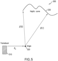
- Figure 5 shows a schematic 500 of geometry for an arbitrary TPS curve and radius smoothing.
- Figure 5 includes a transducer 510, an origin point 520 and a haptic curve 530.
- R t e 0 x + f x t 2 + e 0 y + f y t 2 + e 0 z + f z t 2 .
- mapping function g(t) which smooths the radius function.
- one transducer ( e 0 ) 510 would have a perfect, single-frequency phase function. Other transducers would get increasingly less-perfect as their distances increase from the solved transducer. This method works well if the perfect-transducer for the solver is the farthest one from the haptic interaction.
- Figure 6 shows a graph 600 of the results of applying method 1 smoothing for a line extending from 8 cm to 11 cm in the x-axis extending from the center of an array.
- the x-axis 610 is time in seconds.
- the y-axis 620 is the x value in cm.
- the plot shows a fixed velocity 630 and smooth radius 640 lines. Because the fixed velocity line 630 is already at a spatiotemporal minimum at the start, it is not affected. The far end of the fixed velocity line 630 receives most of the adjustment.
- Shown in Figure 7 is a graph 700 of a phase function for a transducer directly below one end of the line given in Figure 6 .
- the x-axis 710 is time in seconds.
- the y-axis 720 is phase value.
- the plot shows a fixed velocity 740 and smooth radius 730 lines.
- Shown in Figure 8 is a graph 700 of a frequency power spectrum for the two curves shown in Figure 6 .
- the x-axis 810 is frequency in kHz.
- the y-axis 820 is dB.
- the plot shows a fixed velocity 830 and smooth radius 840 lines.
- this method can be implemented in real-time with a sample buffer where points are redistributed in blocks, dividing the curve into increasing and decreasing distance.
- a sufficiently large buffer would be needed so as to always include enough points to divide the space into distinct sections. This would be a function of the update rate and the size of the possible interaction regions.
- An approximation of the previous method may be achieved by manipulating traversal rate on the path so that it has minimum velocity at sharp points which might cause noise.
- P ⁇ t represents a fixed-velocity parametrized TPS curve which starts and stops at a hard location (such as a line)
- a minimum-velocity curve would be,
- P ⁇ smooth t P ⁇ .5 ⁇ .5 cos ⁇ t t f where t f is the time representing the end of the curve.
- the phase functions can be run in reverse. This results in a low-spread power spectrum.
- Figure 9 is a graph 900 showing the application of this method smoothing to a line extending from 8 cm to 11 cm in the x-axis extending from the center of an array.
- the x-axis 910 is time in seconds.
- the y-axis 920 is x-value in cm.
- the plot shows a fixed velocity 930 and temporally radius 640 lines.
- Shown in Figure 10 is a graph 1000 of a phase function for a transducer directly below one end of the line given in Figure 6 .
- the x-axis 1010 is time in seconds.
- the y-axis 1020 is phase value.
- the plot shows a fixed velocity 1030 and temporally smooth 730 lines.
- Shown in Figure 11 is a graph 1100 of a frequency power spectrum for the two curves shown in Figure 6 .
- the x-axis 1110 is frequency in kHz.
- the y-axis 1120 is dB.
- the plot shows a fixed velocity 1130 and smooth radius 1140 lines.
- a sample buffer would have to look ahead for sharp transitions and redistribute to first accelerate to get ahead in space and then decelerate into those points.
- Sub-sampling would be done by assuming each point is itself a "sharp" transition and distributions would follow a smooth function (like above) in between on a direct-line path. This should be especially effective if the accepted point rate is at 400 Hz or less with an update rate of 40 kHz or higher.
- R t e 0 x + f x t 2 + e 0 y + f y t 2 + e 0 z + f z t 2 . From this equation, it is clear that spatial functions ( f x ( t ), etc) with high-frequency content will directly translate to high-frequency content in R(t). If we filter the spatial functions directly, R(t) and therefore the phase function for the curve, will have a minimum of high-frequency content.
- Frequency filtering approaches fall into two categories: ones involving feedback/feedforward called infinite impulse response (IIR) and ones without feedback called finite impulse response (FIR).
- IIR filtering requires less buffering and computation cost but often introduces phase delay.
- FIR filtering can be phase-perfect but requires a buffer equal to the size of the coefficients which can get large for low-frequency filtering.
- Figure 12 shows a graph 1200 of 3 cm 200-point square curve 1230 filtered by a 2 nd order Butterworth (IIR) filter at sampled at 400 Hz (200 Hz).
- the x-axis 1210 is x in cm.
- the y-axis 1220 is y in cm. Shown is one loop of the steady-state response.
- the resulting curve 1240 while not identical to the input curve, is largely indistinguishable using 40 kHz ultrasound due to focusing resolution.
- Figure 13 shows a graph 1300 of the frequency power spectrum for the two curves shown in Figure 12 .
- the x-axis 1310 is frequency in kHz.
- the y-axis 1320 is in dB.
- the plot shows a perfect square 1330 and a filtered square 1340. This is the absolute sum of the output of 256 individual transducers located at 1 cm pitch in a 16 x 16 array. In this case, the data presented represents the sum of all the transducers placed at 1 cm pitch in a 16 x 16 square array.
- Figure 14 shows a graph 1400 of the phase function for a transducer located near the origin in Figure 12 .
- the x-axis 1410 is time in seconds.
- the y-axis 1420 is phase value in dB.
- the plot shows a perfect square 1430 and a filtered square 1440. The smoothing of the phase function for a transducer located under one corner of the square is shown in Figure 14 .
- Filtering can be adjusted to achieve the desired balance between path reproduction accuracy and audio reduction.
- Any input path or series of points representing a path can be approximated with smooth path using curve fitting techniques.
- a haptic path is often repeated several times in order to create a haptic sensation. If a complete loop is buffered in advance, this nicely encapsulates a repetitive sequence and can be expressed as a Fourier series. Being directly related to the frequency domain, increasing orders of approximation directly relates to the trade-off between accuracy and unwanted audio.
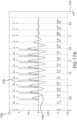
- Figure 15 is a graph 1500 showing an example of a 3 cm square with increasing orders of Fourier series expansion.
- the x-axis 1510 is x in cm.
- the y-axis 1520 is y in cm.
- the plots 1530, 1540, 1550, 1560, 1570 respectfully represent the maximum order included in each expansion of perfect, 1, 3, 5 and 7.
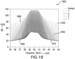
- Figure 16 shows a graph 1600 of the frequency power spectrum for the curves shown in Figure 15 .
- This is the absolute sum of the output of 256 individual transducers located at 1 cm pitch in a 16 x 16 array.
- the x-axis 1610 is frequency in kHz.
- the y-axis 1620 is dB.
- the resulting power spectrums 1630, 1640, 1650, 1660, 1670 show how increasing the order of the approximation (respectively perfect, 7, 5, 3, 1) yields more sidebands and more audio as a result of better path reproduction.
- the approximation would need to be updated every time the haptic loop is updated. Transitioning between them would need another method discussed in this document to avoid high-frequency jumps.
- Polynomial fits are another class of smooth functions which can easily be fit to a set of input points.
- Critical points can be chosen in advance or in a buffered or sub-sampled signal and a fitting routine such as least-squares can be used to fit a low-order polynomial. Selecting critical points with sudden stops or high curvature will likely be the most effective. The higher-order used, the more accurate the curve will be to the input points, but the higher curvature will allow for higher frequency content. Essentially non-oscillatory (ENO) polynomials may also be used to counter this through the weighted selection of high-order polynomial interpolations which are representative yet minimize unwanted high-frequency content.
- ENO non-oscillatory
- the number of critical points could relate to the order of the polynomial fit in order to include those points exactly (a determinate system). If implemented real-time, the fit would need to update smoothly as new critical points are determined.
- Splines offer yet another curve approximation system which can emphasize smoothness and low curvature.
- the input could be critical points from a sub-sampled system or chosen algorithmically from an input buffer.
- V out t V in t ⁇ h t
- V out (t) the output of the system
- V in (t) is the driving signal
- h(t) is the system's impulse response
- * is the convolution operator.
- One way to organize a system is to divide the past of the system into segments each with fixed time interval T. Past drive signals are grouped into equal-time segments and designated by the number of periods in the past they represent.
- V 0 t D 0 t ⁇ h t + D 1 t ⁇ h t ⁇ T + D 2 t ⁇ h t ⁇ 2 T + ⁇
- V 0 and D 0 represent the output and drive of next cycle to be produced and all other terms encapsulate the history of the system.
- This solution may be expanded to an array of coupled systems by measuring the impulse response of one element when another is driven. Take, for example, two elements A and B.
- the impulse response of A when B is driven is defined as h BA and the opposite case of response of B when A is driven as h AB .
- the traditional impulse response in this notation would be h AA and h BB respectively.
- V A 0 D A 0 ⁇ h AA 0 + D A ⁇ h AA + D B 0 ⁇ h BA 0 + D B ⁇ h BA
- V B 0 D B 0 ⁇ h BB 0 + D B ⁇ h BB + D A 0 ⁇ h AB 0 + D A ⁇ h AB
- D a and D B are the vectors of time-series driving data analogous to D above
- V A0 and V B0 are the output of each element.
- V A0 and V B0 When V A0 and V B0 are specified this reduces to an indeterminate system in which a solution can be approximated.
- This technique can be expanded to an arbitrarily sized array of elements. This is the most general form of the invention.
- This formula calculates the necessary drive (D 0 ) for a desired output (V 0 ) given the history of the drive contained in D * h. Presented below are methods to simplify the deconvolution process under certain conditions.
- both the output ( V 0 ), drive ( D 0 ), and first-period impulse response ( h 0 ) would be complex numbers representing the Fourier component at the resonant frequency.
- D and h are vectors containing the time shifted impulse response and drive Fourier components respectively.
- the number of historical data points to include in any one timestep is dependent on the desired accuracy of the drive as well as the computational power available.
- the complex output is relatively easy to realize in practice and will be covered below.
- the impulse response function can be approximate by purely exponential decay.
- ⁇ is an experimentally derived constant.
- Each cycle the previous contribution is multiplied by a and summed with the new cycle. In this way, only one multiplication is necessary each cycle to calculate the complete historical contribution.
- This simplification works very well for systems well described by a damped harmonic oscillator.
- a hybrid recursive filter can be made by including a fixed number of cycles using the previous explicit method and then lumping the remainder into a recursive term. If the bulk of the ringing behavior can be captured in the fixed cycles which are explicitly calculated, the remainder should be well described by a recursive approach.
- D n and A n are the drive and amplitude at n periods in the past and h n is the time-shifted impulse response for that amplitude. In our notation, for the next timestep, this would be incremented to A 1 and used within the historical term in equation 5 above.
- the methods presented above rely on an accurate impulse response. In a real system, this can change under various environmental conditions including temperature, altitude, age, and many others. Accuracy of the methods depend on tracking the most important factors and adjusting the impulse responses accordingly. This can be implemented using a large store of recorded impulse responses which are then accessed based on external sensors or clocks. Alternatively, a different resonant driving frequency can be used which could restore accuracy to the impulse response as most decay and cross talk mechanisms will remain largely similar even if the resonant frequency of the system changes. In another arrangement, a mathematical model of the change in impulse response can be implemented in the system to change the stored impulse response over time and function.
- the device can be setup to measure the impulse response at certain times such as start-up or during periods of minimal output to re-adjust the internal tables. This could be accomplished electrically via an impedance sweep or with some other electrical measuring method. Alternatively, feedback from an external measurement device (such as a microphone for an ultrasonic transducer system) could be used to update tables.
- an external measurement device such as a microphone for an ultrasonic transducer system
- the feed-forward control scheme can introduce some high-frequency components to the drive which could be detrimental in certain applications (high-power airborne ultrasound for instance).
- high-power airborne ultrasound for instance.
- One simple method is to simply apply IIR low-pass filters to the output drive coefficients of equation 1 (one for each of the real and imaginary components). For each cycle, the previous cycle's output is the output of the filter, then a new drive term is calculated with equation 1, and that is filtered, and so on.
- Another option is a simple comparison of the change of D from one cycle to the next and limit this to a certain magnitude (point by point), this limited D is the input to the history term in the next cycle. This is effectively a low-order low-pass filter.
- the filter can adapt to the input, by analyzing the bandwidth of the input and applying a filter which starts to attenuate based on that value.
- a filter which starts to attenuate based on that value.
- a running max change from the previous n input samples could be stored and that could be used as the limiting change. In that way if the input is requesting high-frequency changes, high-frequency changes are passed, but if the input is slow and smooth, the output coefficients are also limited in their rate of change.
- the input signal could be analyzed for frequency content (say with a series of band filters) and an adjustable IIR filter applied to each driving term based upon the input frequency analysis. The exact relationship between the content of the input and filtered output can be adjusted to optimize accuracy (by passing all frequencies) versus noise (heavily filtering).
- Examples shown in the figures are generated using a 2-level PWM interpretation of the coefficient output equation 1. This is done simply by matching the Fourier component of PWM to the desired output by adjusting the phase and width of the pulse. When an amplitude requested exceeds what is possible by the drive, phase can still be preserved by amplitude is kept at maximum duty cycle (50%). This clipping of amplitude does not impede the method and is implemented in the simulations above.
- the invention presented here is not limited to a 2-level PWM drive. Any drive system will work from PWM to analogue. The only requirement is that the drive for each resonant-frequency-period have a Fourier component at that frequency which matches in the output from equation 1. The cleaner the drive is from a frequency perspective, the better the system will perform. This can be achieved by switching many times per cycle, many different voltage levels available, or a full high-bandwidth analogue drive.
- Feed-forward drive allows for the precise control of resonant systems.
- Figures 17A and 17B show a pair of graphs 1700, 1750 that are a simple model demonstration of a basic drive versus feed-forward control (this invention).
- the x-axis 1710, 1760 are unitless scale values.
- the y-axes 1720, 1770 are unitless scale values.
- the curved plot lines 1740, 1790 represent the motion of the system and the straight plot lines 1730, 1780 are the drive.
- Vertical lines denote resonant periods of the model system.
- the system has a rise-time of about 5 cycles.
- the numbers above the curves are the input amplitude and phase and the lower numbers are the resulting output amplitude and phase.
- the drive is only related to the input and the straight plot lines 1730 are the same every cycle.
- the drive uses information about the history of the transducer drive and drives in such a way to both drive harder (at the start) and drive in such a say to damp the motion (at the end). This results in output closer to the input at all points in the control period.
- Figure 18 show a pair of graphs 1800, 1850 showing amplitude and phase accuracy of amplitude-modulated input using regular and feed-forward drive applied to a real-world 40 kHz transducer model.
- the x-axes 1810, 1860 are the 40 kHz period number.
- the y-axis 1820 of the first graph 1800 is output-input magnitude.
- the y-axis 1870 of the second graph 1850 is output-input phase.
- the plot shows normal 1830, 1880 and feed forward 1840, 1890 drive.
- the feed-forward system in all the simulations presented here uses 60 terms in the impulse response. Amplitude modulation desired is 200 Hz and full modulation amplitude.
- Input coefficients are converted to a PWM signal with 100 steps per period to simulate real-world digital drive.
- the first graph 1800 shows the difference of the output to input over 800 periods.
- the second graph 1850 shows the difference in phase between the output to input.
- the feed-forward control 1890 is able to hold the system to better than 2% amplitude accuracy and less than 0.1 radians except near zeros of the amplitude.
- the traditional drive 1880 has more than 10% amplitude error and drifts up to 0.3 radians off target even at non-zero amplitudes.
- Figure 19 shows graphs 1900, 1950 of amplitude and phase accuracy of phase-modulated input using regular and feed-forward drive applied to a real-world 40 kHz transducer model.
- the x-axes 1910, 1960 are the 40 kHz period number.
- the y-axis 1920 of the first graph 1900 is output-input magnitude.
- the y-axis 1970 of the second graph 1950 is output-input phase.
- the plot shows normal 1930, 1980 and feed forward 1940, 1990 drive.
- the input drive is 90% amplitude and 0.7*pi radians amplitude at 200 Hz.
- the transducer is physically not capable of following the requested phase shift as neither system is able to fully match both the amplitude and phase of the requested input.
- Figure 20A are graphs 2000, 2020 that use regular drive
- Figure 20B are graphs 2040, 2060 that use feed-forward drive.
- the x-axes 2005, 2025, 2045, 2065 are the 40 kHz period number.
- the y-axes 2010, 2050 for the magnitude error graphs 2000, 2040 are output-input magnitude.
- the y-axes 2030, 2070 for the phase error graphs 2020, 2060 are output-input phase.
- the plots show results for transducer 1 2015, 2035, 2055, 2075 and for transducer 2 2018, 2038, 2058, 2078.
- These graphs are examples of cross-talk performance showing amplitude and phase accuracy of two strongly-coupled phase-modulated transducers with transducer 2 at 90 degrees out of phase with transducer 1.
- the mathematical model uses the same real-world 40 kHz transducer model as the previous figures with an added coupling losses spring. Input coefficients are converted to a PWM signal with 100 steps per period to emulate real-world digital drive.
- the input drive is 80% amplitude with 0.5*pi radians of modulation at 200 Hz, with transducer 2 at 90 degrees out of phase with transducer 1.
- the graphs 2000, 2020 show the large errors introduced by coupling with the amplitude dropping by as much as 15%.
- the graphs 2040, 2060 show the control possible with feed-forward coupled control, with amplitude and phase accuracy on the order of 2%.
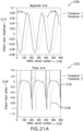
- Figure 21A are graphs 2100, 2120 that use regular drive
- Figure 20B are graphs 2140, 2160 that use feed-forward drive.
- the x-axes 2105, 2125, 2145, 2165 are the 40 kHz period number.
- the y-axes 2110, 2150 for the magnitude error graphs 2100, 2140 are output-input magnitude.
- the y-axes 2130, 2170 for the phase error graphs 2120, 2160 are output-input phase.
- the plots show results for transducer 1 2115, 2135, 2155, 2175 and for transducer 2 2118, 2138, 2158, 2178.
- the mathematical model uses the same real-world 40 kHz transducer model as the previous figures with an added coupling losses spring. Input coefficients are converted to a PWM signal with 100 steps per period to simulate real-world digital drive.
- the input drive is 50% amplitude depth at 200 Hz, with transducer 2 at 90 degrees out of phase with transducer 1.
- the graphs 2100, 2120 show the large errors introduced by coupling: the amplitude is out of phase with drive input in graph 2100 and causes massive phase errors in graph 2120.
- the graphs 2150, 2170 show the control possible with feed-forward coupled control, with amplitude accuracy better than 1% in graph 2140 and phase under tight control except near zero-output in graph 2160.
- Figure 22 shows a graph 2200 of simulations of a nonlinear response for impulse response amplitude of a standard damped oscillator and a damped harmonic oscillator with a nonlinear damping term.
- the x-axis 2210 is n.
- the y-axis 2220 is magnitude.
- the plots 2230, 2240 represent the amplitude decay of a resonant system starting at the amplitude given at the start of the curve (x-axis 2210 value 1).
- the scaled small impulse plot 2230 show a response where decay is exponential (simply proportional to amplitude) and hence is a straight line on a semi-log plot which is expected from a simple damped oscillator. In this case the impulse response can simply be scaled by the starting value.
- the real response plot 2240 show the response of a nonlinear system where the decay of the amplitude is a stronger with higher amplitude and thus deviates more from the simple system when drive is high.
- the method presented in equation 2 uses the full range of impulse response curves produced by different starting amplitudes to work out a correct historical term and more accurately drive the system.
- Figure 23 show graphs 2300, 2350 of amplitude and phase accuracy of amplitude-modulated input using regular and feed-forward drive applied to a real-world 40 kHz transducer model including a nonlinear damping term.
- the x-axes 2310, 2360 are the 40 kHz period number.
- the y-axis 2320 of the first graph 2300 is output-input magnitude.
- the y-axis 2370 of the second graph 2350 is output-input phase.
- the plot shows normal 2330, 2380 and feed forward 2340, 2390 drive.
- Amplitude modulation desired is 200 Hz and full modulation amplitude.
- Input coefficients are converted to a PWM signal with 100 steps per period to simulate real-world digital drive.
- the input amplitude is adjusted to match the nonlinear response curve in the steady state, and this corrected response is what is used to calculate the difference from output.
- the input signal was scaled so that an input of 1 corresponded to the maximum the transducer model was capable of producing (in this case ⁇ 0.77).
- Information regarding the shape of the nonlinearity is contained in the impulse response functions and will automatically fix the curve shape.
- the feed-forward control is able to control the system with better accuracy than traditional methods.
- One inventive step lies in recognizing that the impulse response for a highly-resonant system can be approximated by Fourier components at the resonant frequency (equation 2). This key simplification reduces the deconvolution operator to matrix algebra. Beyond this, manipulating the impulse response to be a function of drive amplitude to compensate for amplitude non-linearities is novel. Also, adapting this to a coupled resonant-system array and solving for the necessary drive as a matrix inversion is new.
Landscapes
- Physics & Mathematics (AREA)
- Engineering & Computer Science (AREA)
- Acoustics & Sound (AREA)
- Health & Medical Sciences (AREA)
- Otolaryngology (AREA)
- Multimedia (AREA)
- Signal Processing (AREA)
- General Physics & Mathematics (AREA)
- Apparatuses For Generation Of Mechanical Vibrations (AREA)
- Transducers For Ultrasonic Waves (AREA)
Claims (13)
- Verfahren, umfassend:
Erzeugen von haptischem Feedback in der Luft unter Verwendung von Ultraschall, umfassend die Schritte:Erzeugen eines akustischen Felds von einem Wandlerarray, das bekannte relative Positionen und Ausrichtungen aufweist,Definieren eines Fokuspunkts, der eine bekannte räumliche Beziehung relativ zum Wandlerarray aufweist, die einen Pfad definiert, der mindestens eine erste Pfaddimension und eine zweite Pfaddimension aufweist und der eine bekannte räumliche Beziehung relativ zum Wandlerarray aufweist, in dem sich der Fokuspunkt bewegen wird,Bewegen des Fokuspunkts in die Nähe des Pfads, so das wenig hörbarer Ton erzeugt wird,wobei der Pfad durch eine Näherungsfunktion unter Verwendung von Kurvenanpassungstechniken angenähert wird,Filtern der Näherungsfunktion in der ersten Pfaddimension und in der zweiten Pfaddimension, so dass der Hochfrequenzgehalt reduziert wird. - Verfahren nach Anspruch 1, ferner umfassend:
Bewegen des Fokuspunkts in die Nähe des Pfads in einer Methode, die ausgewählt ist, so dass eine glatte Phasenfunktion für einen Wandler erzeugt wird. - Verfahren nach Anspruch 1, wobei sich der Fokuspunkt in die Nähe des Pfads bewegt, so dass eine Phasenfunktion mit reduziertem Hochfrequenzgehalt für einen Wandler erzeugt wird.
- Verfahren nach Anspruch 1, wobei sich der Fokuspunkt in die Nähe des Pfads bewegt, so dass ein gleichmäßiger Radius versus Zeit von einem Wandler erzeugt wird.
- Verfahren nach Anspruch 1, wobei sich der Fokuspunkt so bewegt, dass er mehr Zeit in der Nähe von Stellen in der Kurve mit enger Krümmung oder Endpunkten verbringt.
- Verfahren nach Anspruch 1, wobei der Pfad auch eine dritte Pfaddimension aufweist, und Filtern der Näherungsfunktion in der dritten Pfaddimension.
- Verfahren nach Anspruch 1, wobei der Filter ein Filter mit unendlicher Impulsantwort ist.
- Verfahren nach Anspruch 1, wobei der Pfad in mehrere Fokuspunkte unterteilt ist.
- Verfahren nach einem der Ansprüche 1 oder 8, wobei der Filter ein Filter mit endlicher Impulsantwort ist.
- Verfahren nach einem der Ansprüche 8 oder 9, wobei die mehreren Fokuspunkte entlang des Pfads verteilt sind, so dass eine gleichmäßige Phasenfunktion für einen Wandler erzeugt wird.
- Verfahren nach einem der Ansprüche 8 oder 9, wobei die mehreren Fokuspunkte entlang des Pfads verteilt sind, so dass ein gleichmäßiger Radius versus Zeit von einem Wandler erzeugt wird.
- Verfahren nach einem der Ansprüche 8 oder 9, wobei die mehreren Fokuspunkte entlang des Pfads verteilt sind, so dass die mehreren Fokuspunkte an Stellen mit enger Krümmung oder Endpunkten enger verteilt sind.
- Verfahren nach einem der Ansprüche 8 oder 9, wobei räumliche Positionen der mehreren Fokuspunkte gefiltert werden, so dass hochfrequente Inhalte entfernt werden.
Applications Claiming Priority (3)
| Application Number | Priority Date | Filing Date | Title |
|---|---|---|---|
| US201762609429P | 2017-12-22 | 2017-12-22 | |
| US201862777770P | 2018-12-11 | 2018-12-11 | |
| PCT/GB2018/053739 WO2019122916A1 (en) | 2017-12-22 | 2018-12-21 | Minimizing unwanted responses in haptic systems |
Publications (3)
| Publication Number | Publication Date |
|---|---|
| EP3729418A1 EP3729418A1 (de) | 2020-10-28 |
| EP3729418B1 true EP3729418B1 (de) | 2024-11-20 |
| EP3729418C0 EP3729418C0 (de) | 2024-11-20 |
Family
ID=65013724
Family Applications (1)
| Application Number | Title | Priority Date | Filing Date |
|---|---|---|---|
| EP18833495.7A Active EP3729418B1 (de) | 2017-12-22 | 2018-12-21 | Minimierung von unerwünschten antworten in haptischen systemen |
Country Status (4)
| Country | Link |
|---|---|
| US (2) | US11704983B2 (de) |
| EP (1) | EP3729418B1 (de) |
| JP (1) | JP7483610B2 (de) |
| WO (1) | WO2019122916A1 (de) |
Families Citing this family (31)
| Publication number | Priority date | Publication date | Assignee | Title |
|---|---|---|---|---|
| GB2513884B (en) | 2013-05-08 | 2015-06-17 | Univ Bristol | Method and apparatus for producing an acoustic field |
| GB2530036A (en) | 2014-09-09 | 2016-03-16 | Ultrahaptics Ltd | Method and apparatus for modulating haptic feedback |
| ES2908299T3 (es) | 2015-02-20 | 2022-04-28 | Ultrahaptics Ip Ltd | Mejoras del algoritmo en un sistema háptico |
| KR102515997B1 (ko) | 2015-02-20 | 2023-03-29 | 울트라햅틱스 아이피 엘티디 | 햅틱 시스템에서의 인식 |
| US10818162B2 (en) | 2015-07-16 | 2020-10-27 | Ultrahaptics Ip Ltd | Calibration techniques in haptic systems |
| US11189140B2 (en) | 2016-01-05 | 2021-11-30 | Ultrahaptics Ip Ltd | Calibration and detection techniques in haptic systems |
| US10268275B2 (en) | 2016-08-03 | 2019-04-23 | Ultrahaptics Ip Ltd | Three-dimensional perceptions in haptic systems |
| US10943578B2 (en) * | 2016-12-13 | 2021-03-09 | Ultrahaptics Ip Ltd | Driving techniques for phased-array systems |
| US11531395B2 (en) | 2017-11-26 | 2022-12-20 | Ultrahaptics Ip Ltd | Haptic effects from focused acoustic fields |
| EP3729418B1 (de) | 2017-12-22 | 2024-11-20 | Ultrahaptics Ip Ltd | Minimierung von unerwünschten antworten in haptischen systemen |
| WO2019122912A1 (en) | 2017-12-22 | 2019-06-27 | Ultrahaptics Limited | Tracking in haptic systems |
| WO2019211616A1 (en) | 2018-05-02 | 2019-11-07 | Ultrahaptics Limited | Blocking plate structure for improved acoustic transmission efficiency |
| US11098951B2 (en) | 2018-09-09 | 2021-08-24 | Ultrahaptics Ip Ltd | Ultrasonic-assisted liquid manipulation |
| US11378997B2 (en) | 2018-10-12 | 2022-07-05 | Ultrahaptics Ip Ltd | Variable phase and frequency pulse-width modulation technique |
| WO2020141330A2 (en) | 2019-01-04 | 2020-07-09 | Ultrahaptics Ip Ltd | Mid-air haptic textures |
| US12373033B2 (en) | 2019-01-04 | 2025-07-29 | Ultrahaptics Ip Ltd | Mid-air haptic textures |
| US11842517B2 (en) | 2019-04-12 | 2023-12-12 | Ultrahaptics Ip Ltd | Using iterative 3D-model fitting for domain adaptation of a hand-pose-estimation neural network |
| US11374586B2 (en) | 2019-10-13 | 2022-06-28 | Ultraleap Limited | Reducing harmonic distortion by dithering |
| CA3154040A1 (en) * | 2019-10-13 | 2021-04-22 | Benjamin John Oliver LONG | Dynamic capping with virtual microphones |
| WO2021090028A1 (en) | 2019-11-08 | 2021-05-14 | Ultraleap Limited | Tracking techniques in haptics systems |
| US11715453B2 (en) | 2019-12-25 | 2023-08-01 | Ultraleap Limited | Acoustic transducer structures |
| US11816267B2 (en) | 2020-06-23 | 2023-11-14 | Ultraleap Limited | Features of airborne ultrasonic fields |
| US11886639B2 (en) | 2020-09-17 | 2024-01-30 | Ultraleap Limited | Ultrahapticons |
| US12032770B2 (en) | 2020-11-23 | 2024-07-09 | Toyota Motor Engineering & Manufacturing North America, Inc. | Haptic array device and control of focus point height and focus point direction |
| US12383066B2 (en) | 2022-04-26 | 2025-08-12 | Toyota Motor Engineering & Manufacturing North America, Inc. | Chair with shape memory material-based movement synchronized with visual content |
| WO2023220445A2 (en) * | 2022-05-12 | 2023-11-16 | Light Field Lab, Inc. | Haptic devices |
| US12270386B2 (en) | 2023-02-16 | 2025-04-08 | Toyota Motor Engineering & Manufacturing North America, Inc. | Shape memory material member-based actuator |
| US12241458B2 (en) | 2023-02-16 | 2025-03-04 | Toyota Motor Engineering & Manufacturing North America, Inc. | Actuator with contracting member |
| US12152570B2 (en) | 2023-02-22 | 2024-11-26 | Toyota Motor Engineering & Manufacturing North America, Inc. | Shape memory material member-based actuator with electrostatic clutch preliminary class |
| US12163507B2 (en) | 2023-02-22 | 2024-12-10 | Toyota Motor Engineering & Manufacturing North America, Inc. | Contracting member-based actuator with clutch |
| US12234811B1 (en) | 2023-08-21 | 2025-02-25 | Toyota Motor Engineering & Manufacturing North America, Inc. | Monitoring a state of a shape memory material member |
Citations (1)
| Publication number | Priority date | Publication date | Assignee | Title |
|---|---|---|---|---|
| EP3616033A1 (de) * | 2017-04-24 | 2020-03-04 | Ultrahaptics IP Ltd | Algorithmuserweiterungen für haptikbasierte phasengesteuerte phasenarraysysteme |
Family Cites Families (370)
| Publication number | Priority date | Publication date | Assignee | Title |
|---|---|---|---|---|
| US1218921A (en) | 1916-06-27 | 1917-03-13 | Dudley James Barnard | Grab. |
| US4218921A (en) | 1979-07-13 | 1980-08-26 | The United States Of America As Represented By The Administrator Of The National Aeronautics And Space Administration | Method and apparatus for shaping and enhancing acoustical levitation forces |
| CA1175359A (en) | 1981-01-30 | 1984-10-02 | John G. Martner | Arrayed ink jet apparatus |
| FR2551611B1 (fr) | 1983-08-31 | 1986-10-24 | Labo Electronique Physique | Nouvelle structure de transducteur ultrasonore et appareil d'examen de milieux par echographie ultrasonore comprenant une telle structure |
| EP0309003B1 (de) | 1984-02-15 | 1994-12-07 | Trw Inc. | Akustischer Oberflächenwellen-Spektrumanalysator |
| JPS62258597A (ja) | 1986-04-25 | 1987-11-11 | Yokogawa Medical Syst Ltd | 超音波トランスデユ−サ |
| US4760525A (en) | 1986-06-10 | 1988-07-26 | The United States Of America As Represented By The Secretary Of The Air Force | Complex arithmetic vector processor for performing control function, scalar operation, and set-up of vector signal processing instruction |
| US5226000A (en) | 1988-11-08 | 1993-07-06 | Wadia Digital Corporation | Method and system for time domain interpolation of digital audio signals |
| JPH02234600A (ja) | 1989-03-07 | 1990-09-17 | Mitsubishi Mining & Cement Co Ltd | 圧電変換素子 |
| US5235986A (en) | 1990-02-12 | 1993-08-17 | Acuson Corporation | Variable origin-variable angle acoustic scanning method and apparatus for a curved linear array |
| WO1991018486A1 (en) | 1990-05-14 | 1991-11-28 | Commonwealth Scientific And Industrial Research Organisation | A coupling device |
| DE59100463D1 (de) | 1991-02-07 | 1993-11-11 | Siemens Ag | Verfahren zur Herstellung von Ultraschallwandlern. |
| US5243344A (en) | 1991-05-30 | 1993-09-07 | Koulopoulos Michael A | Digital-to-analog converter--preamplifier apparatus |
| JP3243821B2 (ja) | 1992-02-27 | 2002-01-07 | ヤマハ株式会社 | 電子楽器 |
| US5371834A (en) | 1992-08-28 | 1994-12-06 | The United States Of America As Represented By The Administrator Of The National Aeronautics And Space Administration | Adaptive neuron model--an architecture for the rapid learning of nonlinear topological transformations |
| US6216538B1 (en) | 1992-12-02 | 2001-04-17 | Hitachi, Ltd. | Particle handling apparatus for handling particles in fluid by acoustic radiation pressure |
| US5426388A (en) | 1994-02-15 | 1995-06-20 | The Babcock & Wilcox Company | Remote tone burst electromagnetic acoustic transducer pulser |
| US5477736A (en) | 1994-03-14 | 1995-12-26 | General Electric Company | Ultrasonic transducer with lens having electrorheological fluid therein for dynamically focusing and steering ultrasound energy |
| US5511296A (en) | 1994-04-08 | 1996-04-30 | Hewlett Packard Company | Method for making integrated matching layer for ultrasonic transducers |
| CA2155818C (en) | 1994-08-11 | 1998-09-01 | Masahiro Sai | Automatic door opening and closing system |
| AU6162596A (en) | 1995-06-05 | 1996-12-24 | Christian Constantinov | Ultrasonic sound system and method for producing virtual sou nd |
| US5729694A (en) * | 1996-02-06 | 1998-03-17 | The Regents Of The University Of California | Speech coding, reconstruction and recognition using acoustics and electromagnetic waves |
| US7225404B1 (en) | 1996-04-04 | 2007-05-29 | Massachusetts Institute Of Technology | Method and apparatus for determining forces to be applied to a user through a haptic interface |
| US5859915A (en) | 1997-04-30 | 1999-01-12 | American Technology Corporation | Lighted enhanced bullhorn |
| US6193936B1 (en) | 1998-11-09 | 2001-02-27 | Nanogram Corporation | Reactant delivery apparatuses |
| US6029518A (en) | 1997-09-17 | 2000-02-29 | The United States Of America As Represented By The Administrator Of The National Aeronautics And Space Administration | Manipulation of liquids using phased array generation of acoustic radiation pressure |
| US7391872B2 (en) | 1999-04-27 | 2008-06-24 | Frank Joseph Pompei | Parametric audio system |
| US6647359B1 (en) | 1999-07-16 | 2003-11-11 | Interval Research Corporation | System and method for synthesizing music by scanning real or simulated vibrating object |
| US6307302B1 (en) | 1999-07-23 | 2001-10-23 | Measurement Specialities, Inc. | Ultrasonic transducer having impedance matching layer |
| CN100358393C (zh) | 1999-09-29 | 2007-12-26 | 1...有限公司 | 定向声音的方法和设备 |
| US6771294B1 (en) | 1999-12-29 | 2004-08-03 | Petri Pulli | User interface |
| US20010053204A1 (en) | 2000-02-10 | 2001-12-20 | Nassir Navab | Method and apparatus for relative calibration of a mobile X-ray C-arm and an external pose tracking system |
| US6925187B2 (en) | 2000-03-28 | 2005-08-02 | American Technology Corporation | Horn array emitter |
| US6503204B1 (en) | 2000-03-31 | 2003-01-07 | Acuson Corporation | Two-dimensional ultrasonic transducer array having transducer elements in a non-rectangular or hexagonal grid for medical diagnostic ultrasonic imaging and ultrasound imaging system using same |
| US7284027B2 (en) | 2000-05-15 | 2007-10-16 | Qsigma, Inc. | Method and apparatus for high speed calculation of non-linear functions and networks using non-linear function calculations for digital signal processing |
| DE10026077B4 (de) | 2000-05-25 | 2007-03-22 | Siemens Ag | Strahlformungsverfahren |
| JP4822634B2 (ja) | 2000-08-31 | 2011-11-24 | シーメンス アクチエンゲゼルシヤフト | 対象物の案内のための座標変換を求める方法 |
| DE10051133A1 (de) | 2000-10-16 | 2002-05-02 | Siemens Ag | Strahlformungsverfahren |
| US6768921B2 (en) | 2000-12-28 | 2004-07-27 | Z-Tech (Canada) Inc. | Electrical impedance method and apparatus for detecting and diagnosing diseases |
| US7463249B2 (en) | 2001-01-18 | 2008-12-09 | Illinois Tool Works Inc. | Acoustic wave touch actuated switch with feedback |
| US7058147B2 (en) | 2001-02-28 | 2006-06-06 | At&T Corp. | Efficient reduced complexity windowed optimal time domain equalizer for discrete multitone-based DSL modems |
| WO2002100480A2 (en) | 2001-06-13 | 2002-12-19 | Apple Marc G | Brachytherapy device and method |
| US6436051B1 (en) | 2001-07-20 | 2002-08-20 | Ge Medical Systems Global Technology Company, Llc | Electrical connection system for ultrasonic receiver array |
| US7154928B2 (en) | 2004-06-23 | 2006-12-26 | Cymer Inc. | Laser output beam wavefront splitter for bandwidth spectrum control |
| US6758094B2 (en) | 2001-07-31 | 2004-07-06 | Koninklijke Philips Electronics, N.V. | Ultrasonic transducer wafer having variable acoustic impedance |
| WO2003019125A1 (en) | 2001-08-31 | 2003-03-06 | Nanyang Techonological University | Steering of directional sound beams |
| US7623114B2 (en) | 2001-10-09 | 2009-11-24 | Immersion Corporation | Haptic feedback sensations based on audio output from computer devices |
| WO2003050511A1 (en) | 2001-12-13 | 2003-06-19 | The University Of Wyoming Research Corporation Doing Business As Western Research Institute | Volatile organic compound sensor system |
| AU2003217234A1 (en) | 2002-01-18 | 2003-09-02 | American Technology Corporation | Modulator- amplifier |
| US6800987B2 (en) | 2002-01-22 | 2004-10-05 | Measurement Specialties, Inc. | Protective housing for ultrasonic transducer apparatus |
| US20030182647A1 (en) | 2002-03-19 | 2003-09-25 | Radeskog Mattias Dan | Automatic interactive component placement for electronics-CAD software through the use of force simulations |
| FI20020865A7 (fi) * | 2002-05-07 | 2003-11-08 | Genelec Oy | Menetelmä matalataajuisen modaalisen ekvalisaattorin suunnittelemiseksi erityisesti lähekkäin sijaitsevia moodeja varten |
| WO2003101150A1 (de) | 2002-05-27 | 2003-12-04 | Sonicemotion Ag | Verfahren und vorrichtung zur erzeugung von daten über die gegenseitige lage von mindestens drei schallwandlern |
| US20040052387A1 (en) | 2002-07-02 | 2004-03-18 | American Technology Corporation. | Piezoelectric film emitter configuration |
| US7720229B2 (en) | 2002-11-08 | 2010-05-18 | University Of Maryland | Method for measurement of head related transfer functions |
| GB0301093D0 (en) | 2003-01-17 | 2003-02-19 | 1 Ltd | Set-up method for array-type sound systems |
| JP4192672B2 (ja) | 2003-05-16 | 2008-12-10 | 株式会社日本自動車部品総合研究所 | 超音波センサ |
| WO2005010623A2 (en) | 2003-07-24 | 2005-02-03 | Zebra Imaging, Inc. | Enhanced environment visualization using holographic stereograms |
| WO2005017965A2 (en) | 2003-08-06 | 2005-02-24 | Measurement Specialities, Inc. | Ultrasonic air transducer arrays using polymer piezoelectric films and impedance matching structures for ultrasonic polymer transducer arrays |
| DE10342263A1 (de) | 2003-09-11 | 2005-04-28 | Infineon Technologies Ag | Optoelektronisches Bauelement und optoelektronische Anordnung mit einem optoelektronischen Bauelement |
| US20050148874A1 (en) | 2003-12-19 | 2005-07-07 | Brock-Fisher George A. | Ultrasonic imaging aberration correction with microbeamforming |
| EP1698086A2 (de) | 2003-12-27 | 2006-09-06 | Electronics and Telecommunications Research Institute | Mimo-ofdm-system mit eigenstrahlformungs-verfahren |
| US20050212760A1 (en) | 2004-03-23 | 2005-09-29 | Marvit David L | Gesture based user interface supporting preexisting symbols |
| CA2600196A1 (en) | 2004-03-29 | 2005-10-20 | Peter T. German | Systems and methods to determine elastic properties of materials |
| JP5243025B2 (ja) | 2004-05-17 | 2013-07-24 | エポス ディベロップメント リミテッド | 音響測位システムのための頑健な音響同期シグナリング |
| US7689639B2 (en) | 2004-06-04 | 2010-03-30 | Telefonaktiebolaget Lm Ericsson (Publ) | Complex logarithmic ALU |
| WO2006044868A1 (en) | 2004-10-20 | 2006-04-27 | Nervonix, Inc. | An active electrode, bio-impedance based, tissue discrimination system and methods and use |
| US7138620B2 (en) | 2004-10-29 | 2006-11-21 | Silicon Light Machines Corporation | Two-dimensional motion sensor |
| US20060090955A1 (en) | 2004-11-04 | 2006-05-04 | George Cardas | Microphone diaphragms defined by logarithmic curves and microphones for use therewith |
| US7692661B2 (en) | 2005-01-26 | 2010-04-06 | Pixar | Method of creating and evaluating bandlimited noise for computer graphics |
| WO2006086743A2 (en) | 2005-02-09 | 2006-08-17 | American Technology Corporation | In-band parametric sound generation system |
| US7345600B1 (en) | 2005-03-09 | 2008-03-18 | Texas Instruments Incorporated | Asynchronous sampling rate converter |
| GB0508194D0 (en) | 2005-04-22 | 2005-06-01 | The Technology Partnership Plc | Pump |
| US8398541B2 (en) | 2006-06-06 | 2013-03-19 | Intuitive Surgical Operations, Inc. | Interactive user interfaces for robotic minimally invasive surgical systems |
| WO2015006467A1 (en) | 2013-07-09 | 2015-01-15 | Coactive Drive Corporation | Synchronized array of vibration actuators in an integrated module |
| US9459632B2 (en) | 2005-06-27 | 2016-10-04 | Coactive Drive Corporation | Synchronized array of vibration actuators in a network topology |
| GB2427918B (en) | 2005-07-01 | 2009-01-28 | David Richard Andrews | A monitoring system |
| US7233722B2 (en) | 2005-08-15 | 2007-06-19 | General Display, Ltd. | System and method for fiber optics based direct view giant screen flat panel display |
| CN101461254B (zh) | 2005-09-20 | 2017-11-07 | 皇家飞利浦电子股份有限公司 | 具有长端口的带通换能器系统 |
| EP1775989B1 (de) | 2005-10-12 | 2008-12-10 | Yamaha Corporation | Lautsprecher- und Mikrofonanordnung |
| US20070094317A1 (en) | 2005-10-25 | 2007-04-26 | Broadcom Corporation | Method and system for B-spline interpolation of a one-dimensional signal using a fractional interpolation ratio |
| US8312479B2 (en) | 2006-03-08 | 2012-11-13 | Navisense | Application programming interface (API) for sensory events |
| US20070216711A1 (en) | 2006-03-14 | 2007-09-20 | Microsoft Corporation Microsoft Patent Group | Abstracting transform representations in a graphics API |
| US8405618B2 (en) | 2006-03-24 | 2013-03-26 | Northwestern University | Haptic device with indirect haptic feedback |
| DE102007020593A1 (de) | 2006-05-01 | 2007-11-08 | Ident Technology Ag | Eingabeeinrichtung |
| CN101466432A (zh) | 2006-06-14 | 2009-06-24 | 皇家飞利浦电子股份有限公司 | 用于经皮给药的设备和操作这种设备的方法 |
| US7425874B2 (en) | 2006-06-30 | 2008-09-16 | Texas Instruments Incorporated | All-digital phase-locked loop for a digital pulse-width modulator |
| US7497662B2 (en) | 2006-07-31 | 2009-03-03 | General Electric Company | Methods and systems for assembling rotatable machines |
| US20100030076A1 (en) | 2006-08-01 | 2010-02-04 | Kobi Vortman | Systems and Methods for Simultaneously Treating Multiple Target Sites |
| JP2008074075A (ja) | 2006-09-25 | 2008-04-03 | Canon Inc | 画像形成装置及びその制御方法 |
| EP1911530B1 (de) | 2006-10-09 | 2009-07-22 | Baumer Electric AG | Ultraschallwandler mit akustischer Impedanzanpassung |
| WO2008064230A2 (en) | 2006-11-20 | 2008-05-29 | Personics Holdings Inc. | Methods and devices for hearing damage notification and intervention ii |
| US8351646B2 (en) | 2006-12-21 | 2013-01-08 | Honda Motor Co., Ltd. | Human pose estimation and tracking using label assignment |
| KR100889726B1 (ko) | 2007-02-02 | 2009-03-24 | 한국전자통신연구원 | 촉각 자극 장치 및 이를 응용한 장치 |
| FR2912817B1 (fr) | 2007-02-21 | 2009-05-22 | Super Sonic Imagine Sa | Procede d'optimisation de la focalisation d'ondes au travers d'un element introducteur d'aberations. |
| DE102007018266A1 (de) | 2007-04-10 | 2008-10-16 | Seereal Technologies S.A. | Holographisches Projektionssystem mit einer optischen Wellennachführung und Mitteln zum Korrigieren der holographischen Rekonstruktion |
| US8269168B1 (en) | 2007-04-30 | 2012-09-18 | Physical Logic Ag | Meta materials integration, detection and spectral analysis |
| US9100748B2 (en) | 2007-05-04 | 2015-08-04 | Bose Corporation | System and method for directionally radiating sound |
| KR100919236B1 (ko) | 2007-05-22 | 2009-09-30 | 한국전자통신연구원 | 병렬 프로세서를 이용한 3차원 그래픽 기하 변환 방법 |
| US9317110B2 (en) | 2007-05-29 | 2016-04-19 | Cfph, Llc | Game with hand motion control |
| WO2009050990A1 (ja) | 2007-10-16 | 2009-04-23 | Murata Manufacturing Co., Ltd. | 圧電マイクロブロア |
| FR2923612B1 (fr) | 2007-11-12 | 2011-05-06 | Super Sonic Imagine | Dispositif d'insonification comprenant un reseau tridimensionnel d'emetteurs disposes en spirale apte a generer un faisceau d'ondes focalisees de grande intensite |
| FI20075879A0 (fi) | 2007-12-05 | 2007-12-05 | Valtion Teknillinen | Laite paineen, äänenpaineen vaihtelun, magneettikentän, kiihtyvyyden, tärinän ja kaasun koostumuksen mittaamiseksi |
| US20100262008A1 (en) | 2007-12-13 | 2010-10-14 | Koninklijke Philips Electronics N.V. | Robotic ultrasound system with microadjustment and positioning control using feedback responsive to acquired image data |
| GB0804739D0 (en) | 2008-03-14 | 2008-04-16 | The Technology Partnership Plc | Pump |
| US20090251421A1 (en) | 2008-04-08 | 2009-10-08 | Sony Ericsson Mobile Communications Ab | Method and apparatus for tactile perception of digital images |
| US8369973B2 (en) | 2008-06-19 | 2013-02-05 | Texas Instruments Incorporated | Efficient asynchronous sample rate conversion |
| US8731851B2 (en) | 2008-07-08 | 2014-05-20 | Bruel & Kjaer Sound & Vibration Measurement A/S | Method for reconstructing an acoustic field |
| US20100013613A1 (en) | 2008-07-08 | 2010-01-21 | Jonathan Samuel Weston | Haptic feedback projection system |
| US8162840B2 (en) | 2008-07-16 | 2012-04-24 | Syneron Medical Ltd | High power ultrasound transducer |
| WO2010015086A1 (en) | 2008-08-06 | 2010-02-11 | Creaform Inc. | System for adaptive three-dimensional scanning of surface characteristics |
| GB2464117B (en) | 2008-10-03 | 2015-01-28 | Hiwave Technologies Uk Ltd | Touch sensitive device |
| JP2010109579A (ja) | 2008-10-29 | 2010-05-13 | Nippon Telegr & Teleph Corp <Ntt> | 音響出力素子アレイ及び音響出力方法 |
| US8199953B2 (en) | 2008-10-30 | 2012-06-12 | Avago Technologies Wireless Ip (Singapore) Pte. Ltd. | Multi-aperture acoustic horn |
| US9769003B2 (en) * | 2011-12-12 | 2017-09-19 | John W. Bogdan | Direct synthesis of OFDM receiver clock |
| US9569001B2 (en) | 2009-02-03 | 2017-02-14 | Massachusetts Institute Of Technology | Wearable gestural interface |
| US10564721B2 (en) | 2009-03-12 | 2020-02-18 | Immersion Corporation | Systems and methods for using multiple actuators to realize textures |
| JP5477736B2 (ja) | 2009-03-25 | 2014-04-23 | 独立行政法人放射線医学総合研究所 | 粒子線照射装置 |
| US20120031193A1 (en) * | 2009-04-01 | 2012-02-09 | Purdue Research Foundation | Identification of loads acting on an object |
| WO2010125797A1 (ja) | 2009-04-28 | 2010-11-04 | パナソニック株式会社 | 補聴装置、及び補聴方法 |
| US8009022B2 (en) | 2009-05-29 | 2011-08-30 | Microsoft Corporation | Systems and methods for immersive interaction with virtual objects |
| JP2012528980A (ja) | 2009-06-03 | 2012-11-15 | ザ テクノロジー パートナーシップ ピーエルシー | 流体ディスクポンプ |
| US7920078B2 (en) | 2009-06-19 | 2011-04-05 | Conexant Systems, Inc. | Systems and methods for variable rate conversion |
| EP2271129A1 (de) | 2009-07-02 | 2011-01-05 | Nxp B.V. | Wandler mit resonantem Hohlraum |
| KR20110005587A (ko) | 2009-07-10 | 2011-01-18 | 삼성전자주식회사 | 휴대 단말의 진동 발생 방법 및 장치 |
| US20110010958A1 (en) | 2009-07-16 | 2011-01-20 | Wayne Clark | Quiet hair dryer |
| US9177543B2 (en) | 2009-08-26 | 2015-11-03 | Insightec Ltd. | Asymmetric ultrasound phased-array transducer for dynamic beam steering to ablate tissues in MRI |
| GB0916707D0 (en) | 2009-09-23 | 2009-11-04 | Elliptic Laboratories As | Acoustic motion determination |
| US8027224B2 (en) | 2009-11-11 | 2011-09-27 | Brown David A | Broadband underwater acoustic transducer |
| US9084045B2 (en) | 2009-12-11 | 2015-07-14 | Sorama Holding B.V. | Acoustic transducer assembly |
| RU2563061C2 (ru) | 2009-12-28 | 2015-09-20 | Конинклейке Филипс Электроникс Н.В. | Оптимизация преобразователя сфокусированного ультразвука высокой интенсивности |
| KR20110093379A (ko) | 2010-02-12 | 2011-08-18 | 주식회사 팬택 | 채널상태정보 피드백 장치와 그 방법, 기지국, 그 기지국의 전송방법 |
| US20110199342A1 (en) | 2010-02-16 | 2011-08-18 | Harry Vartanian | Apparatus and method for providing elevated, indented or texturized sensations to an object near a display device or input detection using ultrasound |
| JP5457874B2 (ja) | 2010-02-19 | 2014-04-02 | 日本電信電話株式会社 | 局所再生装置とその方法と、プログラム |
| US9357280B2 (en) | 2010-04-20 | 2016-05-31 | Nokia Technologies Oy | Apparatus having an acoustic display |
| WO2011138784A1 (en) | 2010-05-05 | 2011-11-10 | Technion Research & Development Foundation Ltd. | Method and system of operating a multi focused acoustic wave source |
| US8519982B2 (en) * | 2010-06-21 | 2013-08-27 | Sony Corporation | Active acoustic touch location for electronic devices |
| NZ587483A (en) | 2010-08-20 | 2012-12-21 | Ind Res Ltd | Holophonic speaker system with filters that are pre-configured based on acoustic transfer functions |
| JP5343946B2 (ja) | 2010-08-25 | 2013-11-13 | 株式会社デンソー | 触覚提示装置 |
| US8782109B2 (en) | 2010-09-10 | 2014-07-15 | Texas Instruments Incorporated | Asynchronous sample rate conversion using a polynomial interpolator with minimax stopband attenuation |
| US8607922B1 (en) | 2010-09-10 | 2013-12-17 | Harman International Industries, Inc. | High frequency horn having a tuned resonant cavity |
| US8422721B2 (en) | 2010-09-14 | 2013-04-16 | Frank Rizzello | Sound reproduction systems and method for arranging transducers therein |
| US20120113223A1 (en) | 2010-11-05 | 2012-05-10 | Microsoft Corporation | User Interaction in Augmented Reality |
| KR101221513B1 (ko) | 2010-12-13 | 2013-01-21 | 가천대학교 산학협력단 | 시각 장애인에게 시각 정보를 촉각 정보로 전달하는 그래픽 햅틱전자보드 및 방법 |
| DE102011017250B4 (de) | 2011-01-07 | 2022-12-01 | Maxim Integrated Products, Inc. | Berührungs-Feedbacksystem, haptisches Feedbacksystem und Verfahren zum Bereitstellen eines haptischen Feedbacks |
| CA2824865A1 (en) | 2011-01-18 | 2012-07-26 | Bayer Intellectual Property Gmbh | Flexure apparatus, system, and method |
| US9076429B2 (en) | 2011-01-31 | 2015-07-07 | Wayne State University | Acoustic metamaterials |
| GB201101870D0 (en) | 2011-02-03 | 2011-03-23 | The Technology Partnership Plc | Pump |
| BR112013023981A2 (pt) | 2011-03-22 | 2016-12-13 | Koninkl Philips Nv | conjunto de células cmut de um transdutor ultrassônico |
| JP5367001B2 (ja) | 2011-03-24 | 2013-12-11 | ツインバード工業株式会社 | ドライヤー |
| US10061387B2 (en) | 2011-03-31 | 2018-08-28 | Nokia Technologies Oy | Method and apparatus for providing user interfaces |
| WO2012135378A1 (en) | 2011-04-01 | 2012-10-04 | Analog Devices, Inc. | Method and apparatus for haptic vibration response profiling and feedback |
| CN103608749B (zh) | 2011-04-26 | 2016-12-07 | 加利福尼亚大学董事会 | 用于记录和重现感觉的系统和装置 |
| US8833510B2 (en) | 2011-05-05 | 2014-09-16 | Massachusetts Institute Of Technology | Phononic metamaterials for vibration isolation and focusing of elastic waves |
| US9421291B2 (en) | 2011-05-12 | 2016-08-23 | Fifth Third Bank | Hand dryer with sanitizing ionization assembly |
| US20120299853A1 (en) | 2011-05-26 | 2012-11-29 | Sumit Dagar | Haptic interface |
| KR101290763B1 (ko) | 2011-06-08 | 2013-07-29 | 가천대학교 산학협력단 | 햅틱전자보드 기반의 시각 장애인용 학습정보 제공 시스템 및 방법 |
| JP5594435B2 (ja) | 2011-08-03 | 2014-09-24 | 株式会社村田製作所 | 超音波トランスデューサ |
| US9417754B2 (en) | 2011-08-05 | 2016-08-16 | P4tents1, LLC | User interface system, method, and computer program product |
| US20150209564A1 (en) | 2011-09-02 | 2015-07-30 | Drexel University | Ultrasound device and therapeutic methods |
| KR20190133080A (ko) | 2011-09-19 | 2019-11-29 | 아이사이트 모빌 테크놀로지 엘티디 | 증강 현실 시스템용 터치프리 인터페이스 |
| JP2014531589A (ja) | 2011-09-22 | 2014-11-27 | コーニンクレッカ フィリップス エヌ ヴェ | 多方向測定のための超音波測定アセンブリ |
| US9143879B2 (en) | 2011-10-19 | 2015-09-22 | James Keith McElveen | Directional audio array apparatus and system |
| US20130100008A1 (en) | 2011-10-19 | 2013-04-25 | Stefan J. Marti | Haptic Response Module |
| PL2663575T3 (pl) | 2011-10-28 | 2015-03-31 | Regeneron Pharma | Humanizowane IL-6 i receptor IL-6 |
| KR101355532B1 (ko) | 2011-11-21 | 2014-01-24 | 알피니언메디칼시스템 주식회사 | 고강도 집속 초음파용 트랜스듀서 |
| US9269037B2 (en) | 2011-12-29 | 2016-02-23 | Mighty Cast, Inc. | Interactive base and token capable of communicating with computing device |
| US9513053B2 (en) | 2013-03-14 | 2016-12-06 | Revive Electronics, LLC | Methods and apparatuses for drying electronic devices |
| US8493354B1 (en) | 2012-08-23 | 2013-07-23 | Immersion Corporation | Interactivity model for shared feedback on mobile devices |
| US20120223880A1 (en) | 2012-02-15 | 2012-09-06 | Immersion Corporation | Method and apparatus for producing a dynamic haptic effect |
| US8711118B2 (en) | 2012-02-15 | 2014-04-29 | Immersion Corporation | Interactivity model for shared feedback on mobile devices |
| KR102046102B1 (ko) | 2012-03-16 | 2019-12-02 | 삼성전자주식회사 | 메타물질의 코일 기반 인공원자, 이를 포함하는 메타물질 및 소자 |
| US9448635B2 (en) | 2012-04-16 | 2016-09-20 | Qualcomm Incorporated | Rapid gesture re-engagement |
| US8570296B2 (en) | 2012-05-16 | 2013-10-29 | Immersion Corporation | System and method for display of multiple data channels on a single haptic display |
| GB201208853D0 (en) | 2012-05-18 | 2012-07-04 | Hiwave Technologies Uk Ltd | Panel for use in vibratory panel device |
| EP2855034B1 (de) | 2012-05-31 | 2020-09-09 | Koninklijke Philips N.V. | Ultraschallwandleranordnung und verfahren zum ansteuern eines ultraschallwandlerkopfes |
| CA2876175C (en) | 2012-06-08 | 2021-07-27 | A.L.M. Holding Company | Biodiesel emulsion for cleaning bituminous coated equipment |
| WO2014011727A1 (en) | 2012-07-10 | 2014-01-16 | President And Fellows Of Harvard College | Articulated character fabrication |
| EP2702935A1 (de) | 2012-08-29 | 2014-03-05 | Agfa HealthCare N.V. | System und Verfahren zur optischen Kohärenztomographie sowie Positionierelement |
| US9552673B2 (en) | 2012-10-17 | 2017-01-24 | Microsoft Technology Licensing, Llc | Grasping virtual objects in augmented reality |
| IL223086A (en) | 2012-11-18 | 2017-09-28 | Noveto Systems Ltd | System and method for creating sonic fields |
| US8947387B2 (en) | 2012-12-13 | 2015-02-03 | Immersion Corporation | System and method for identifying users and selecting a haptic response |
| US9459697B2 (en) | 2013-01-15 | 2016-10-04 | Leap Motion, Inc. | Dynamic, free-space user interactions for machine control |
| US12453853B2 (en) | 2013-01-21 | 2025-10-28 | Cala Health, Inc. | Multi-modal stimulation for treating tremor |
| US9202313B2 (en) | 2013-01-21 | 2015-12-01 | Microsoft Technology Licensing, Llc | Virtual interaction with image projection |
| US9323397B2 (en) | 2013-03-11 | 2016-04-26 | The Regents Of The University Of California | In-air ultrasonic rangefinding and angle estimation |
| US9208664B1 (en) | 2013-03-11 | 2015-12-08 | Amazon Technologies, Inc. | Adjusting structural characteristics of a device |
| EP2973538B1 (de) | 2013-03-13 | 2019-05-22 | BAE SYSTEMS plc | Ein metamaterial |
| US9436282B2 (en) | 2013-03-14 | 2016-09-06 | Immersion Corporation | Contactor-based haptic feedback generation |
| US10181314B2 (en) | 2013-03-15 | 2019-01-15 | Elwha Llc | Portable electronic device directed audio targeted multiple user system and method |
| US20140269207A1 (en) | 2013-03-15 | 2014-09-18 | Elwha Llc | Portable Electronic Device Directed Audio Targeted User System and Method |
| US10531190B2 (en) | 2013-03-15 | 2020-01-07 | Elwha Llc | Portable electronic device directed audio system and method |
| US10291983B2 (en) | 2013-03-15 | 2019-05-14 | Elwha Llc | Portable electronic device directed audio system and method |
| US9886941B2 (en) | 2013-03-15 | 2018-02-06 | Elwha Llc | Portable electronic device directed audio targeted user system and method |
| US9647464B2 (en) | 2013-03-15 | 2017-05-09 | Fujifilm Sonosite, Inc. | Low noise power sources for portable electronic systems |
| US20170238807A9 (en) | 2013-03-15 | 2017-08-24 | LX Medical, Inc. | Tissue imaging and image guidance in luminal anatomic structures and body cavities |
| US9367136B2 (en) | 2013-04-12 | 2016-06-14 | Microsoft Technology Licensing, Llc | Holographic object feedback |
| EP3575941A1 (de) | 2013-04-26 | 2019-12-04 | Immersion Corporation | Haptische ausgabevorrichtungen mit passiver steifheit und aktiver verformung für flexible anzeigevorrichtungen und entsprechendes verfahren |
| GB2513884B (en) | 2013-05-08 | 2015-06-17 | Univ Bristol | Method and apparatus for producing an acoustic field |
| JP6505089B2 (ja) | 2013-06-12 | 2019-04-24 | アトラス・コプコ・インダストリアル・テクニーク・アクチボラグ | 動力工具で実行したファスナーの伸びを超音波で測定する方法及び動力工具 |
| JP2015028766A (ja) | 2013-06-24 | 2015-02-12 | パナソニックIpマネジメント株式会社 | 触感呈示装置および触感呈示方法 |
| US8884927B1 (en) | 2013-06-27 | 2014-11-11 | Elwha Llc | Tactile feedback generated by phase conjugation of ultrasound surface acoustic waves |
| US9804675B2 (en) | 2013-06-27 | 2017-10-31 | Elwha Llc | Tactile feedback generated by non-linear interaction of surface acoustic waves |
| US20150006645A1 (en) | 2013-06-28 | 2015-01-01 | Jerry Oh | Social sharing of video clips |
| US9613456B2 (en) | 2013-06-28 | 2017-04-04 | Disney Enterprises, Inc. | Enhanced dual quaternion skinning with scale non-compensating joints and support joints |
| WO2014209405A1 (en) | 2013-06-29 | 2014-12-31 | Intel Corporation | System and method for adaptive haptic effects |
| GB2516820A (en) | 2013-07-01 | 2015-02-11 | Nokia Corp | An apparatus |
| US20150019299A1 (en) | 2013-07-12 | 2015-01-15 | Joseph Harvey | Method of Generating Golf Index Reports |
| US10408613B2 (en) | 2013-07-12 | 2019-09-10 | Magic Leap, Inc. | Method and system for rendering virtual content |
| US10359857B2 (en) | 2013-07-18 | 2019-07-23 | Immersion Corporation | Usable hidden controls with haptic feedback |
| KR101484230B1 (ko) | 2013-07-24 | 2015-01-16 | 현대자동차 주식회사 | 차량용 터치 디스플레이 장치 및 그 구동 방법 |
| JP2015035657A (ja) | 2013-08-07 | 2015-02-19 | 株式会社豊田中央研究所 | 報知装置及び入力装置 |
| US9576084B2 (en) | 2013-08-27 | 2017-02-21 | Halliburton Energy Services, Inc. | Generating a smooth grid for simulating fluid flow in a well system environment |
| US9576445B2 (en) | 2013-09-06 | 2017-02-21 | Immersion Corp. | Systems and methods for generating haptic effects associated with an envelope in audio signals |
| US20150078136A1 (en) | 2013-09-13 | 2015-03-19 | Mitsubishi Heavy Industries, Ltd. | Conformable Transducer With Self Position Sensing |
| WO2015039622A1 (en) | 2013-09-19 | 2015-03-26 | The Hong Kong University Of Science And Technology | Active control of membrane-type acoustic metamaterial |
| KR101550601B1 (ko) | 2013-09-25 | 2015-09-07 | 현대자동차 주식회사 | 촉감 피드백을 제공하는 곡면 터치 디스플레이 장치 및 그 방법 |
| EP2863654B1 (de) | 2013-10-17 | 2018-08-01 | Oticon A/s | Verfahren zur Wiedergabe eines akustischen Schallfeldes |
| EP2868277B1 (de) | 2013-11-04 | 2017-03-01 | Surgivisio | Verfahren zur rekonstruktion eines 3d-bildes aus 2d-röntgenbildern |
| GB201322103D0 (en) | 2013-12-13 | 2014-01-29 | The Technology Partnership Plc | Fluid pump |
| US9366588B2 (en) | 2013-12-16 | 2016-06-14 | Lifescan, Inc. | Devices, systems and methods to determine area sensor |
| US9612658B2 (en) | 2014-01-07 | 2017-04-04 | Ultrahaptics Ip Ltd | Method and apparatus for providing tactile sensations |
| US9543917B2 (en) * | 2014-01-24 | 2017-01-10 | Fabrice Gabriel Paumier | Software for manipulating equalization curves |
| JP6311197B2 (ja) | 2014-02-13 | 2018-04-18 | 本田技研工業株式会社 | 音響処理装置、及び音響処理方法 |
| US9945818B2 (en) | 2014-02-23 | 2018-04-17 | Qualcomm Incorporated | Ultrasonic authenticating button |
| US10203762B2 (en) | 2014-03-11 | 2019-02-12 | Magic Leap, Inc. | Methods and systems for creating virtual and augmented reality |
| US9679197B1 (en) | 2014-03-13 | 2017-06-13 | Leap Motion, Inc. | Biometric aware object detection and tracking |
| US9649558B2 (en) | 2014-03-14 | 2017-05-16 | Sony Interactive Entertainment Inc. | Gaming device with rotatably placed cameras |
| KR101464327B1 (ko) | 2014-03-27 | 2014-11-25 | 연세대학교 산학협력단 | 3차원 에어터치 피드백 장치, 시스템 및 방법 |
| KR20150118813A (ko) | 2014-04-15 | 2015-10-23 | 삼성전자주식회사 | 햅틱 정보 운용 방법 및 이를 지원하는 전자 장치 |
| US10013083B2 (en) | 2014-04-28 | 2018-07-03 | Qualcomm Incorporated | Utilizing real world objects for user input |
| WO2016022187A2 (en) | 2014-05-12 | 2016-02-11 | Chirp Microsystems | Time of flight range finding with an adaptive transmit pulse and adaptive receiver processing |
| US10579207B2 (en) | 2014-05-14 | 2020-03-03 | Purdue Research Foundation | Manipulating virtual environment using non-instrumented physical object |
| CN106687885B (zh) | 2014-05-15 | 2020-03-03 | 联邦快递公司 | 用于信使处理的可穿戴设备及其使用方法 |
| CN103984414B (zh) | 2014-05-16 | 2018-12-25 | 北京智谷睿拓技术服务有限公司 | 产生触感反馈的方法和设备 |
| WO2015191599A2 (en) | 2014-06-09 | 2015-12-17 | Terumo Bct, Inc. | Lyophilization |
| WO2015194510A1 (ja) | 2014-06-17 | 2015-12-23 | 国立大学法人名古屋工業大学 | 静音化した超音波集束装置 |
| KR101687017B1 (ko) | 2014-06-25 | 2016-12-16 | 한국과학기술원 | 머리 착용형 컬러 깊이 카메라를 활용한 손 위치 추정 장치 및 방법, 이를 이용한 맨 손 상호작용 시스템 |
| FR3023036A1 (fr) | 2014-06-27 | 2016-01-01 | Orange | Re-echantillonnage par interpolation d'un signal audio pour un codage / decodage a bas retard |
| WO2016007920A1 (en) | 2014-07-11 | 2016-01-14 | New York University | Three dimensional tactile feedback system |
| KR101659050B1 (ko) | 2014-07-14 | 2016-09-23 | 한국기계연구원 | 메타물질을 이용한 공기접합 초음파 탐촉자 |
| US9600083B2 (en) | 2014-07-15 | 2017-03-21 | Immersion Corporation | Systems and methods to generate haptic feedback for skin-mediated interactions |
| JP2016035646A (ja) | 2014-08-01 | 2016-03-17 | 株式会社デンソー | 触覚装置、および、それを有する触覚ディスプレイ |
| US9525944B2 (en) | 2014-08-05 | 2016-12-20 | The Boeing Company | Apparatus and method for an active and programmable acoustic metamaterial |
| EP3189520B1 (de) | 2014-09-05 | 2021-11-17 | The University of Washington | Beschränkung oder bewegung eines objekts unter verwendung fokussierter ultraschallwellen zur erzeugung einer ultraschallintensitätskavität |
| GB2530036A (en) | 2014-09-09 | 2016-03-16 | Ultrahaptics Ltd | Method and apparatus for modulating haptic feedback |
| US9936908B1 (en) | 2014-11-03 | 2018-04-10 | Verily Life Sciences Llc | In vivo analyte detection system |
| EP3216231B1 (de) | 2014-11-07 | 2019-08-21 | Chirp Microsystems, Inc. | Gehäusewellenleiter für akustischen sensor mit elektronischer verzögerungskompensation |
| US10427034B2 (en) | 2014-12-17 | 2019-10-01 | Igt Canada Solutions Ulc | Contactless tactile feedback on gaming terminal with 3D display |
| CA2875033C (en) | 2014-12-17 | 2022-07-26 | Fayez Idris | Contactless tactile feedback on gaming terminal with 3d display |
| KR101650821B1 (ko) | 2014-12-19 | 2016-08-24 | 주식회사 고영테크놀러지 | 옵티컬 트래킹 시스템 및 옵티컬 트래킹 시스템의 트래킹 방법 |
| NL2014025B1 (en) | 2014-12-19 | 2016-10-12 | Umc Utrecht Holding Bv | High intensity focused ultrasound apparatus. |
| US9779713B2 (en) | 2014-12-24 | 2017-10-03 | United Technologies Corporation | Acoustic metamaterial gate |
| EP3244804B1 (de) | 2015-01-13 | 2018-12-12 | Koninklijke Philips N.V. | Verfahren, vorrichtungen und systeme zur elektrischen verbindungskupplung mit einem interposer |
| GB2539368A (en) | 2015-02-09 | 2016-12-21 | Univ Erasmus Med Ct Rotterdam | Intravascular photoacoustic imaging |
| US9786092B2 (en) | 2015-02-18 | 2017-10-10 | The Regents Of The University Of California | Physics-based high-resolution head and neck biomechanical models |
| ES2908299T3 (es) | 2015-02-20 | 2022-04-28 | Ultrahaptics Ip Ltd | Mejoras del algoritmo en un sistema háptico |
| KR102515997B1 (ko) | 2015-02-20 | 2023-03-29 | 울트라햅틱스 아이피 엘티디 | 햅틱 시스템에서의 인식 |
| US9911232B2 (en) | 2015-02-27 | 2018-03-06 | Microsoft Technology Licensing, Llc | Molding and anchoring physically constrained virtual environments to real-world environments |
| EP3266224B1 (de) | 2015-04-08 | 2021-05-19 | Huawei Technologies Co., Ltd. | Vorrichtung und verfahren zur ansteuerung einer gruppe von lautsprechern |
| WO2016168117A2 (en) | 2015-04-14 | 2016-10-20 | John James Daniels | Wearable electric, multi-sensory, human/machine, human/human interfaces |
| AU2016100399B4 (en) | 2015-04-17 | 2017-02-02 | Apple Inc. | Contracting and elongating materials for providing input and output for an electronic device |
| WO2016171651A1 (en) | 2015-04-20 | 2016-10-27 | Hewlett-Packard Development Company, L.P. | Tunable filters |
| WO2016182832A1 (en) | 2015-05-08 | 2016-11-17 | Ut-Battelle, Llc | Dryer using high frequency vibration |
| KR20180036652A (ko) | 2015-05-24 | 2018-04-09 | 리보닉스 인코포레이티드 | 표면을 소독하기 위한 시스템 및 방법 |
| US11125866B2 (en) | 2015-06-04 | 2021-09-21 | Chikayoshi Sumi | Measurement and imaging instruments and beamforming method |
| US9711050B2 (en) | 2015-06-05 | 2017-07-18 | Bao Tran | Smart vehicle |
| US10210858B2 (en) | 2015-06-30 | 2019-02-19 | Pixie Dust Technologies, Inc. | System and method for manipulating objects in a computational acoustic-potential field |
| US10818162B2 (en) | 2015-07-16 | 2020-10-27 | Ultrahaptics Ip Ltd | Calibration techniques in haptic systems |
| US9865072B2 (en) | 2015-07-23 | 2018-01-09 | Disney Enterprises, Inc. | Real-time high-quality facial performance capture |
| US10313012B2 (en) | 2015-08-03 | 2019-06-04 | Phase Sensitive Innovations, Inc. | Distributed array for direction and frequency finding |
| US10416306B2 (en) | 2015-08-17 | 2019-09-17 | Texas Instruments Incorporated | Methods and apparatus to measure and analyze vibration signatures |
| US11334165B1 (en) | 2015-09-03 | 2022-05-17 | sigmund lindsay clements | Augmented reality glasses images in midair having a feel when touched |
| US11106273B2 (en) | 2015-10-30 | 2021-08-31 | Ostendo Technologies, Inc. | System and methods for on-body gestural interfaces and projection displays |
| US10318008B2 (en) | 2015-12-15 | 2019-06-11 | Purdue Research Foundation | Method and system for hand pose detection |
| US20170181725A1 (en) | 2015-12-25 | 2017-06-29 | General Electric Company | Joint ultrasound imaging system and method |
| CN105511514B (zh) * | 2015-12-31 | 2019-03-15 | 歌尔股份有限公司 | 一种智能终端的触觉振动控制系统和方法 |
| US11189140B2 (en) | 2016-01-05 | 2021-11-30 | Ultrahaptics Ip Ltd | Calibration and detection techniques in haptic systems |
| US9818294B2 (en) | 2016-01-06 | 2017-11-14 | Honda Motor Co., Ltd. | System for indicating vehicle presence and method thereof |
| EP3207817A1 (de) | 2016-02-17 | 2017-08-23 | Koninklijke Philips N.V. | Ultraschalltrocknen und -formen von haaren |
| CN107179826B (zh) | 2016-03-11 | 2021-08-31 | 松下知识产权经营株式会社 | 姿势输入系统和姿势输入方法 |
| US10091344B2 (en) | 2016-03-28 | 2018-10-02 | International Business Machines Corporation | Displaying virtual target window on mobile device based on user intent |
| US10877559B2 (en) | 2016-03-29 | 2020-12-29 | Intel Corporation | System to provide tactile feedback during non-contact interaction |
| US9936324B2 (en) | 2016-04-04 | 2018-04-03 | Pixie Dust Technologies, Inc. | System and method for generating spatial sound using ultrasound |
| US9667173B1 (en) | 2016-04-26 | 2017-05-30 | Turtle Beach Corporation | Electrostatic parametric transducer and related methods |
| US10228758B2 (en) | 2016-05-20 | 2019-03-12 | Disney Enterprises, Inc. | System for providing multi-directional and multi-person walking in virtual reality environments |
| US10140776B2 (en) | 2016-06-13 | 2018-11-27 | Microsoft Technology Licensing, Llc | Altering properties of rendered objects via control points |
| US10531212B2 (en) | 2016-06-17 | 2020-01-07 | Ultrahaptics Ip Ltd. | Acoustic transducers in haptic systems |
| CN106127780B (zh) | 2016-06-28 | 2019-01-18 | 华南理工大学 | 一种曲面表面缺陷自动检测方法及其装置 |
| US10489927B2 (en) | 2016-07-18 | 2019-11-26 | King Abdullah University Of Science And Technology | System and method for three-dimensional image reconstruction using an absolute orientation sensor |
| US10268275B2 (en) | 2016-08-03 | 2019-04-23 | Ultrahaptics Ip Ltd | Three-dimensional perceptions in haptic systems |
| US10755538B2 (en) | 2016-08-09 | 2020-08-25 | Ultrahaptics ilP LTD | Metamaterials and acoustic lenses in haptic systems |
| CA3033852C (en) | 2016-08-15 | 2023-04-11 | Georgia Tech Research Corporation | Electronic device and method of controlling the same |
| US10394317B2 (en) | 2016-09-15 | 2019-08-27 | International Business Machines Corporation | Interaction with holographic image notification |
| US10945080B2 (en) | 2016-11-18 | 2021-03-09 | Stages Llc | Audio analysis and processing system |
| US10373452B2 (en) | 2016-11-29 | 2019-08-06 | Immersion Corporation | Targeted haptic projection |
| US10943578B2 (en) | 2016-12-13 | 2021-03-09 | Ultrahaptics Ip Ltd | Driving techniques for phased-array systems |
| EP3555812B1 (de) | 2016-12-15 | 2022-07-06 | Google LLC | Umwandlung von quelldomänenbildern in zieldomänenbilder |
| US10497358B2 (en) | 2016-12-23 | 2019-12-03 | Ultrahaptics Ip Ltd | Transducer driver |
| US10839591B2 (en) | 2017-01-04 | 2020-11-17 | Nvidia Corporation | Stereoscopic rendering using raymarching and a virtual view broadcaster for such rendering |
| US10289909B2 (en) | 2017-03-06 | 2019-05-14 | Xerox Corporation | Conditional adaptation network for image classification |
| JP7164078B2 (ja) | 2017-03-17 | 2022-11-01 | 国立大学法人東北大学 | トランスデューサアレイ、光音響プローブ、及び光音響計測装置 |
| JP6239796B1 (ja) | 2017-04-05 | 2017-11-29 | 京セラ株式会社 | 電子機器 |
| US20190197840A1 (en) * | 2017-04-24 | 2019-06-27 | Ultrahaptics Ip Ltd | Grouping and Optimization of Phased Ultrasonic Transducers for Multi-Field Solutions |
| US20180304310A1 (en) | 2017-04-24 | 2018-10-25 | Ultrahaptics Ip Ltd | Interference Reduction Techniques in Haptic Systems |
| US10469973B2 (en) | 2017-04-28 | 2019-11-05 | Bose Corporation | Speaker array systems |
| US11521060B2 (en) | 2017-05-31 | 2022-12-06 | Intel Corporation | Tensor-based computing system for quaternion operations |
| EP3409380A1 (de) | 2017-05-31 | 2018-12-05 | Nxp B.V. | Akustischer prozessor |
| US10168782B1 (en) | 2017-06-05 | 2019-01-01 | Rockwell Collins, Inc. | Ultrasonic haptic feedback control system and method |
| CN107340871A (zh) | 2017-07-25 | 2017-11-10 | 深识全球创新科技(北京)有限公司 | 集成手势识别与超声波触觉反馈的装置及其方法和用途 |
| US11048329B1 (en) | 2017-07-27 | 2021-06-29 | Emerge Now Inc. | Mid-air ultrasonic haptic interface for immersive computing environments |
| US10327974B2 (en) | 2017-08-02 | 2019-06-25 | Immersion Corporation | Haptic implants |
| US11693113B2 (en) | 2017-09-01 | 2023-07-04 | The Trustees Of Princeton University | Quantitative ultrasound imaging based on seismic full waveform inversion |
| US10535174B1 (en) | 2017-09-14 | 2020-01-14 | Electronic Arts Inc. | Particle-based inverse kinematic rendering system |
| US10512839B2 (en) | 2017-09-28 | 2019-12-24 | Igt | Interacting with three-dimensional game elements using gaze detection |
| US10593101B1 (en) | 2017-11-01 | 2020-03-17 | Facebook Technologies, Llc | Marker based tracking |
| US11531395B2 (en) | 2017-11-26 | 2022-12-20 | Ultrahaptics Ip Ltd | Haptic effects from focused acoustic fields |
| US11269047B2 (en) | 2017-12-06 | 2022-03-08 | Invensense, Inc. | Three dimensional object-localization and tracking using ultrasonic pulses with synchronized inertial position determination |
| US10559295B1 (en) * | 2017-12-08 | 2020-02-11 | Jonathan S. Abel | Artificial reverberator room size control |
| EP3729234B1 (de) | 2017-12-22 | 2023-06-07 | Ultrahaptics IP Ltd | Menschliche interaktionen mit haptischen systemen in der luft |
| EP3729418B1 (de) | 2017-12-22 | 2024-11-20 | Ultrahaptics Ip Ltd | Minimierung von unerwünschten antworten in haptischen systemen |
| WO2019122912A1 (en) * | 2017-12-22 | 2019-06-27 | Ultrahaptics Limited | Tracking in haptic systems |
| US11080874B1 (en) | 2018-01-05 | 2021-08-03 | Facebook Technologies, Llc | Apparatuses, systems, and methods for high-sensitivity active illumination imaging |
| US11175739B2 (en) | 2018-01-26 | 2021-11-16 | Immersion Corporation | Method and device for performing actuator control based on an actuator model |
| US10972643B2 (en) | 2018-03-29 | 2021-04-06 | Microsoft Technology Licensing, Llc | Camera comprising an infrared illuminator and a liquid crystal optical filter switchable between a reflection state and a transmission state for infrared imaging and spectral imaging, and method thereof |
| US20190310710A1 (en) | 2018-04-04 | 2019-10-10 | Ultrahaptics Limited | Dynamic Haptic Feedback Systems |
| WO2019204506A1 (en) | 2018-04-17 | 2019-10-24 | California Institute Of Technology | Cross amplitude modulation ultrasound pulse sequence |
| SE541717C2 (en) | 2018-04-27 | 2019-12-03 | Myvox Ab | A device, system and method for generating an acoustic-potential field of ultrasonic waves |
| WO2019211616A1 (en) | 2018-05-02 | 2019-11-07 | Ultrahaptics Limited | Blocking plate structure for improved acoustic transmission efficiency |
| CN112385142B (zh) | 2018-05-11 | 2024-04-05 | 纳诺塞米有限公司 | 用于非线性系统的数字补偿器 |
| GB201810711D0 (en) | 2018-06-29 | 2018-08-15 | King S College London | Ultrasound Method and Apparatus |
| CN109101111B (zh) | 2018-08-24 | 2021-01-29 | 吉林大学 | 融合静电力、空气压膜和机械振动的触觉再现方法与装置 |
| JP7014100B2 (ja) | 2018-08-27 | 2022-02-01 | 日本電信電話株式会社 | 拡張装置、拡張方法及び拡張プログラム |
| US10915792B2 (en) | 2018-09-06 | 2021-02-09 | Nec Corporation | Domain adaptation for instance detection and segmentation |
| US20200082804A1 (en) | 2018-09-09 | 2020-03-12 | Ultrahaptics Ip Ltd | Event Triggering in Phased-Array Systems |
| US11098951B2 (en) | 2018-09-09 | 2021-08-24 | Ultrahaptics Ip Ltd | Ultrasonic-assisted liquid manipulation |
| US10383694B1 (en) | 2018-09-12 | 2019-08-20 | Johnson & Johnson Innovation—Jjdc, Inc. | Machine-learning-based visual-haptic feedback system for robotic surgical platforms |
| US11378997B2 (en) | 2018-10-12 | 2022-07-05 | Ultrahaptics Ip Ltd | Variable phase and frequency pulse-width modulation technique |
| CN109523526B (zh) | 2018-11-08 | 2021-10-22 | 腾讯科技(深圳)有限公司 | 组织结节检测及其模型训练方法、装置、设备和系统 |
| US10599434B1 (en) | 2018-12-14 | 2020-03-24 | Raytheon Company | Providing touch gesture recognition to a legacy windowed software application |
| KR102756358B1 (ko) | 2018-12-18 | 2025-01-17 | 삼성전자주식회사 | 검출기, 객체 검출 방법, 학습기 및 도메인 변환을 위한 학습 방법 |
| KR102230421B1 (ko) | 2018-12-28 | 2021-03-22 | 한국과학기술원 | 가상 모델 제어 방법 및 장치 |
| WO2020141330A2 (en) | 2019-01-04 | 2020-07-09 | Ultrahaptics Ip Ltd | Mid-air haptic textures |
| US12373033B2 (en) | 2019-01-04 | 2025-07-29 | Ultrahaptics Ip Ltd | Mid-air haptic textures |
| KR102791242B1 (ko) | 2019-02-13 | 2025-04-09 | 현대자동차주식회사 | 자율주행차량의 제스처 인터페이스 시스템 및 그 동작 방법 |
| US20200285888A1 (en) | 2019-03-08 | 2020-09-10 | Myntra Designs Private Limited | Domain adaptation system and method for identification of similar images |
| US11475247B2 (en) | 2019-04-02 | 2022-10-18 | Synthesis Ai, Inc. | System and method for adaptive generation using feedback from a trained model |
| US11842517B2 (en) | 2019-04-12 | 2023-12-12 | Ultrahaptics Ip Ltd | Using iterative 3D-model fitting for domain adaptation of a hand-pose-estimation neural network |
| CA3154040A1 (en) | 2019-10-13 | 2021-04-22 | Benjamin John Oliver LONG | Dynamic capping with virtual microphones |
| US11374586B2 (en) | 2019-10-13 | 2022-06-28 | Ultraleap Limited | Reducing harmonic distortion by dithering |
| EP4042270B1 (de) | 2019-10-13 | 2025-03-19 | Ultraleap Limited | Hardware-algorithmus zur komplexwertigen potenzierung und logarithmus, der vereinfachte unterschritte verwendet |
| WO2021090028A1 (en) | 2019-11-08 | 2021-05-14 | Ultraleap Limited | Tracking techniques in haptics systems |
| US11715453B2 (en) | 2019-12-25 | 2023-08-01 | Ultraleap Limited | Acoustic transducer structures |
| WO2021202170A1 (en) | 2020-03-30 | 2021-10-07 | University Of Florida Research Foundation | Collaborative feature ensembling adaptation for domain adaptation in unsupervised optic disc and cup segmentation |
| US20210303758A1 (en) | 2020-03-31 | 2021-09-30 | Ultraleap Limited | Accelerated Hardware Using Dual Quaternions |
| US11669661B2 (en) | 2020-06-15 | 2023-06-06 | Palo Alto Research Center Incorporated | Automated design and optimization for accessibility in subtractive manufacturing |
| US11092491B1 (en) | 2020-06-22 | 2021-08-17 | Microsoft Technology Licensing, Llc | Switchable multi-spectrum optical sensor |
| US11816267B2 (en) | 2020-06-23 | 2023-11-14 | Ultraleap Limited | Features of airborne ultrasonic fields |
| US11937976B2 (en) | 2020-07-06 | 2024-03-26 | 1929803 Ontario Corp | Ultrasound patch with integrated flexible transducer assembly |
| US11301090B2 (en) | 2020-07-30 | 2022-04-12 | Ncr Corporation | Methods, system, and apparatus for touchless terminal interface interaction |
| US11886639B2 (en) | 2020-09-17 | 2024-01-30 | Ultraleap Limited | Ultrahapticons |
| WO2022101642A1 (en) | 2020-11-16 | 2022-05-19 | Ultraleap Limited | Intent driven dynamic gesture recognition system |
| US20220252550A1 (en) | 2021-01-26 | 2022-08-11 | Ultraleap Limited | Ultrasound Acoustic Field Manipulation Techniques |
| WO2022254205A1 (en) | 2021-06-02 | 2022-12-08 | Ultraleap Limited | Electromechanical transducer mount |
| US20230036123A1 (en) | 2021-07-15 | 2023-02-02 | Ultraleap Limited | Control Point Manipulation Techniques in Haptic Systems |
| US20230075917A1 (en) | 2021-08-29 | 2023-03-09 | Ultraleap Limited | Stimulating the Hairy Skin Through Ultrasonic Mid-Air Haptic Stimulation |
| US20230215248A1 (en) | 2022-01-02 | 2023-07-06 | Ultraleap Limited | Mid-Air Haptic Generation Analytic Techniques |
| US11830352B1 (en) | 2022-08-10 | 2023-11-28 | International Business Machines Corporation | Haptic vibration exposure control based on directional position of power recovery module |
| US20240056655A1 (en) | 2022-08-11 | 2024-02-15 | Ultraleap Limited | Visible Background Rejection Techniques for Shared-Camera Hardware |
| US20240129655A1 (en) | 2022-10-11 | 2024-04-18 | Ultraleap Limited | Acoustic Transducer Mounts |
-
2018
- 2018-12-21 EP EP18833495.7A patent/EP3729418B1/de active Active
- 2018-12-21 WO PCT/GB2018/053739 patent/WO2019122916A1/en not_active Ceased
- 2018-12-21 US US16/229,091 patent/US11704983B2/en active Active
- 2018-12-21 JP JP2020534353A patent/JP7483610B2/ja active Active
-
2023
- 2023-05-24 US US18/322,779 patent/US12347304B2/en active Active
Patent Citations (1)
| Publication number | Priority date | Publication date | Assignee | Title |
|---|---|---|---|---|
| EP3616033A1 (de) * | 2017-04-24 | 2020-03-04 | Ultrahaptics IP Ltd | Algorithmuserweiterungen für haptikbasierte phasengesteuerte phasenarraysysteme |
Also Published As
| Publication number | Publication date |
|---|---|
| JP7483610B2 (ja) | 2024-05-15 |
| WO2019122916A1 (en) | 2019-06-27 |
| EP3729418C0 (de) | 2024-11-20 |
| EP3729418A1 (de) | 2020-10-28 |
| JP2021508423A (ja) | 2021-03-04 |
| US20190197842A1 (en) | 2019-06-27 |
| US12347304B2 (en) | 2025-07-01 |
| US11704983B2 (en) | 2023-07-18 |
| US20230298444A1 (en) | 2023-09-21 |
Similar Documents
| Publication | Publication Date | Title |
|---|---|---|
| EP3729418B1 (de) | Minimierung von unerwünschten antworten in haptischen systemen | |
| US10164609B2 (en) | Fractional scaling digital signal processing | |
| Swanson | Signal processing for intelligent sensor systems with MATLAB | |
| TWI626566B (zh) | 觸覺裝置 | |
| KR101021895B1 (ko) | 음향 필드 표현을 처리하기 위한 방법 및 시스템 | |
| EP1766358B1 (de) | System und verfahren zur gleichzeitigen steuerung von spektrum und kurtosis einer nicht periodischen schwingung | |
| US9740662B2 (en) | Fractional scaling digital filters and the generation of standardized noise and synthetic data series | |
| KR20170116162A (ko) | 햅틱 시스템에서의 알고리즘 개선 | |
| JP2612697B2 (ja) | 振動制御装置 | |
| Bilbao et al. | Modeling continuous source distributions in wave-based virtual acoustics | |
| Mayrhofer et al. | A new method for sound generation based on digital sound reconstruction | |
| CN102543091A (zh) | 一种模拟音效的生成系统及方法 | |
| Tyurina et al. | Spectral modeling of difference-frequency generation in the case of two-frequency interaction of ultrasound waves | |
| KR101667481B1 (ko) | 탄성파 트레이스 내삽을 위한 방법 및 그 장치 | |
| Yang et al. | Beam Control of Parametric Array Loudspeakers | |
| JP7501010B2 (ja) | 設定支援装置 | |
| Eklund | Modulation Methods and Beamforming Techniques on a Steerable Parametric Acoustic Array Loudspeaker | |
| Vorländer | Signal Processing for Auralization | |
| Norton et al. | Time domain modeling of pulse propagation in non-isotropic dispersive media | |
| Demi et al. | Modeling nonlinear medical ultrasound via a linearized contrast source method | |
| Lamoureux et al. | Minimum phase and attenuation models in continuous time | |
| Hughes et al. | Bio-Inspired Approach to Quantify | |
| Zajner | MATLAB Model of the Echoplex EP-4 Tape Delay | |
| Zambon | Accurate sound synthesis of 3D object collisions in interactive virtual scenarios | |
| Verweij et al. | Performance study of the iterative nonlinear contrast source method |
Legal Events
| Date | Code | Title | Description |
|---|---|---|---|
| STAA | Information on the status of an ep patent application or granted ep patent |
Free format text: STATUS: UNKNOWN |
|
| STAA | Information on the status of an ep patent application or granted ep patent |
Free format text: STATUS: THE INTERNATIONAL PUBLICATION HAS BEEN MADE |
|
| PUAI | Public reference made under article 153(3) epc to a published international application that has entered the european phase |
Free format text: ORIGINAL CODE: 0009012 |
|
| STAA | Information on the status of an ep patent application or granted ep patent |
Free format text: STATUS: REQUEST FOR EXAMINATION WAS MADE |
|
| 17P | Request for examination filed |
Effective date: 20200720 |
|
| AK | Designated contracting states |
Kind code of ref document: A1 Designated state(s): AL AT BE BG CH CY CZ DE DK EE ES FI FR GB GR HR HU IE IS IT LI LT LU LV MC MK MT NL NO PL PT RO RS SE SI SK SM TR |
|
| AX | Request for extension of the european patent |
Extension state: BA ME |
|
| DAV | Request for validation of the european patent (deleted) | ||
| DAX | Request for extension of the european patent (deleted) | ||
| RIN1 | Information on inventor provided before grant (corrected) |
Inventor name: KAPPUS, BRIAN Inventor name: LONG, BENJAMIN JOHN OLIVER |
|
| STAA | Information on the status of an ep patent application or granted ep patent |
Free format text: STATUS: EXAMINATION IS IN PROGRESS |
|
| 17Q | First examination report despatched |
Effective date: 20230309 |
|
| GRAP | Despatch of communication of intention to grant a patent |
Free format text: ORIGINAL CODE: EPIDOSNIGR1 |
|
| STAA | Information on the status of an ep patent application or granted ep patent |
Free format text: STATUS: GRANT OF PATENT IS INTENDED |
|
| INTG | Intention to grant announced |
Effective date: 20240612 |
|
| GRAS | Grant fee paid |
Free format text: ORIGINAL CODE: EPIDOSNIGR3 |
|
| GRAA | (expected) grant |
Free format text: ORIGINAL CODE: 0009210 |
|
| STAA | Information on the status of an ep patent application or granted ep patent |
Free format text: STATUS: THE PATENT HAS BEEN GRANTED |
|
| AK | Designated contracting states |
Kind code of ref document: B1 Designated state(s): AL AT BE BG CH CY CZ DE DK EE ES FI FR GB GR HR HU IE IS IT LI LT LU LV MC MK MT NL NO PL PT RO RS SE SI SK SM TR |
|
| REG | Reference to a national code |
Ref country code: GB Ref legal event code: FG4D |
|
| REG | Reference to a national code |
Ref country code: CH Ref legal event code: EP |
|
| REG | Reference to a national code |
Ref country code: DE Ref legal event code: R096 Ref document number: 602018076798 Country of ref document: DE |
|
| REG | Reference to a national code |
Ref country code: IE Ref legal event code: FG4D |
|
| U01 | Request for unitary effect filed |
Effective date: 20241127 |
|
| U07 | Unitary effect registered |
Designated state(s): AT BE BG DE DK EE FI FR IT LT LU LV MT NL PT RO SE SI Effective date: 20241209 |
|
| PGFP | Annual fee paid to national office [announced via postgrant information from national office to epo] |
Ref country code: GB Payment date: 20241213 Year of fee payment: 7 |
|
| U20 | Renewal fee for the european patent with unitary effect paid |
Year of fee payment: 7 Effective date: 20241213 |
|
| PG25 | Lapsed in a contracting state [announced via postgrant information from national office to epo] |
Ref country code: HR Free format text: LAPSE BECAUSE OF FAILURE TO SUBMIT A TRANSLATION OF THE DESCRIPTION OR TO PAY THE FEE WITHIN THE PRESCRIBED TIME-LIMIT Effective date: 20241120 Ref country code: IS Free format text: LAPSE BECAUSE OF FAILURE TO SUBMIT A TRANSLATION OF THE DESCRIPTION OR TO PAY THE FEE WITHIN THE PRESCRIBED TIME-LIMIT Effective date: 20250320 |
|
| PG25 | Lapsed in a contracting state [announced via postgrant information from national office to epo] |
Ref country code: ES Free format text: LAPSE BECAUSE OF FAILURE TO SUBMIT A TRANSLATION OF THE DESCRIPTION OR TO PAY THE FEE WITHIN THE PRESCRIBED TIME-LIMIT Effective date: 20241120 |
|
| PG25 | Lapsed in a contracting state [announced via postgrant information from national office to epo] |
Ref country code: NO Free format text: LAPSE BECAUSE OF FAILURE TO SUBMIT A TRANSLATION OF THE DESCRIPTION OR TO PAY THE FEE WITHIN THE PRESCRIBED TIME-LIMIT Effective date: 20250220 |
|
| PG25 | Lapsed in a contracting state [announced via postgrant information from national office to epo] |
Ref country code: GR Free format text: LAPSE BECAUSE OF FAILURE TO SUBMIT A TRANSLATION OF THE DESCRIPTION OR TO PAY THE FEE WITHIN THE PRESCRIBED TIME-LIMIT Effective date: 20250221 |
|
| PG25 | Lapsed in a contracting state [announced via postgrant information from national office to epo] |
Ref country code: PL Free format text: LAPSE BECAUSE OF FAILURE TO SUBMIT A TRANSLATION OF THE DESCRIPTION OR TO PAY THE FEE WITHIN THE PRESCRIBED TIME-LIMIT Effective date: 20241120 |
|
| PG25 | Lapsed in a contracting state [announced via postgrant information from national office to epo] |
Ref country code: RS Free format text: LAPSE BECAUSE OF FAILURE TO SUBMIT A TRANSLATION OF THE DESCRIPTION OR TO PAY THE FEE WITHIN THE PRESCRIBED TIME-LIMIT Effective date: 20250220 |
|
| PG25 | Lapsed in a contracting state [announced via postgrant information from national office to epo] |
Ref country code: SM Free format text: LAPSE BECAUSE OF FAILURE TO SUBMIT A TRANSLATION OF THE DESCRIPTION OR TO PAY THE FEE WITHIN THE PRESCRIBED TIME-LIMIT Effective date: 20241120 |
|
| PG25 | Lapsed in a contracting state [announced via postgrant information from national office to epo] |
Ref country code: SK Free format text: LAPSE BECAUSE OF FAILURE TO SUBMIT A TRANSLATION OF THE DESCRIPTION OR TO PAY THE FEE WITHIN THE PRESCRIBED TIME-LIMIT Effective date: 20241120 |
|
| PG25 | Lapsed in a contracting state [announced via postgrant information from national office to epo] |
Ref country code: CZ Free format text: LAPSE BECAUSE OF FAILURE TO SUBMIT A TRANSLATION OF THE DESCRIPTION OR TO PAY THE FEE WITHIN THE PRESCRIBED TIME-LIMIT Effective date: 20241120 |
|
| REG | Reference to a national code |
Ref country code: CH Ref legal event code: PL |
|
| PG25 | Lapsed in a contracting state [announced via postgrant information from national office to epo] |
Ref country code: MC Free format text: LAPSE BECAUSE OF FAILURE TO SUBMIT A TRANSLATION OF THE DESCRIPTION OR TO PAY THE FEE WITHIN THE PRESCRIBED TIME-LIMIT Effective date: 20241120 |
|
| PLBE | No opposition filed within time limit |
Free format text: ORIGINAL CODE: 0009261 |
|
| STAA | Information on the status of an ep patent application or granted ep patent |
Free format text: STATUS: NO OPPOSITION FILED WITHIN TIME LIMIT |
|
| PG25 | Lapsed in a contracting state [announced via postgrant information from national office to epo] |
Ref country code: CH Free format text: LAPSE BECAUSE OF NON-PAYMENT OF DUE FEES Effective date: 20241231 |
|
| 26N | No opposition filed |
Effective date: 20250821 |
|
| PG25 | Lapsed in a contracting state [announced via postgrant information from national office to epo] |
Ref country code: IE Free format text: LAPSE BECAUSE OF NON-PAYMENT OF DUE FEES Effective date: 20241221 |