WO2010125797A1 - 補聴装置、及び補聴方法 - Google Patents
補聴装置、及び補聴方法 Download PDFInfo
- Publication number
- WO2010125797A1 WO2010125797A1 PCT/JP2010/002996 JP2010002996W WO2010125797A1 WO 2010125797 A1 WO2010125797 A1 WO 2010125797A1 JP 2010002996 W JP2010002996 W JP 2010002996W WO 2010125797 A1 WO2010125797 A1 WO 2010125797A1
- Authority
- WO
- WIPO (PCT)
- Prior art keywords
- acoustic signal
- hand
- hearing aid
- phase difference
- signal
- Prior art date
Links
Images


Classifications
-
- H—ELECTRICITY
- H04—ELECTRIC COMMUNICATION TECHNIQUE
- H04R—LOUDSPEAKERS, MICROPHONES, GRAMOPHONE PICK-UPS OR LIKE ACOUSTIC ELECTROMECHANICAL TRANSDUCERS; DEAF-AID SETS; PUBLIC ADDRESS SYSTEMS
- H04R25/00—Deaf-aid sets, i.e. electro-acoustic or electro-mechanical hearing aids; Electric tinnitus maskers providing an auditory perception
- H04R25/40—Arrangements for obtaining a desired directivity characteristic
- H04R25/407—Circuits for combining signals of a plurality of transducers
-
- H—ELECTRICITY
- H04—ELECTRIC COMMUNICATION TECHNIQUE
- H04R—LOUDSPEAKERS, MICROPHONES, GRAMOPHONE PICK-UPS OR LIKE ACOUSTIC ELECTROMECHANICAL TRANSDUCERS; DEAF-AID SETS; PUBLIC ADDRESS SYSTEMS
- H04R2225/00—Details of deaf aids covered by H04R25/00, not provided for in any of its subgroups
- H04R2225/61—Aspects relating to mechanical or electronic switches or control elements, e.g. functioning
Definitions
- the present invention relates to a hearing aid apparatus and a hearing aid method that can detect a user's hand-holding action based on an input signal from each microphone.
- Hearing aids are equipped with several switches, such as volume control, but the switches installed on the main body are very small and are often difficult to operate when worn on the ear. Therefore, if the user can operate the hearing aid by a gesture (hereinafter referred to as a hand-holding operation) in which the user of the hearing aid holds his / her hand over his / her ear, the operation of the hearing aid becomes easy.
- a gesture hereinafter referred to as a hand-holding operation
- Patent Document 1 discloses an apparatus having a hand-holding motion detection function that can detect a hand-holding motion by a distance sensor. When a hand-holding operation is detected, a sound source for listening to headphones can be selected.
- FIG. 18 is a schematic configuration diagram showing a configuration 1600 that realizes the hand-holding motion detection function disclosed in Patent Document 1.
- the infrared distance sensor 1611 measures the distance to an object close to it. As shown in FIG. 18, when the distance ⁇ between the palm 1612 of the user and the infrared distance sensor 1611 is within a certain range, the hand-holding operation can be detected.
- Patent Document 2 the time difference of the phase difference spectrum pattern is detected by using the fact that the phase difference spectrum pattern input from the two microphones changes according to the surrounding situation without using the distance sensor.
- An apparatus is disclosed.
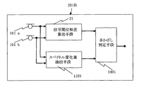
- FIG. 19 is a block diagram showing a configuration of an apparatus for detecting a time change due to a spectrum pattern of a phase difference in Patent Document 2.
- two input phase difference spectra are calculated from input signals from microphones 1901a and 1901b by frequency analysis means 1713a and 1713b and phase difference spectrum calculation means 1714 using fast Fourier transform.
- the temporal change of the phase difference spectrum is detected by the temporal change detection means 1715, and the change in the space is detected by the change determination means 1716 in space based on the result detected by the temporal change detection means 1715.
- Patent Document 3 discloses a headphone device that performs a predetermined process by detecting an operation of a user hitting the device housing.
- the headphone device is provided with an electro-acoustic conversion means for reproducing and outputting an audio signal, and an acousto-electric conversion means at a position where the reproduced audio can be collected.
- the judging means judges whether or not a predetermined operation has been performed on the casing. Then, when it is determined that a predetermined operation has been performed on the housing, the control means controls the device to perform a predetermined process, thereby operating the device without using an operation button or the like. It can be carried out.
- Non-Patent Document 1 There are several switches installed in the hearing aid.
- some recent hearing aids have two or more microphones and are equipped with a function of enhancing the forward sound by directional signal processing (see Non-Patent Document 1, for example).
- the hearing aid that performs directional signal processing in accordance with the sound in front is provided with a directional mode switch, and is configured so that the user can be switched according to the surrounding environment.
- switches on the hearing aid body such as volume control switches, but the volume of the hearing aid device itself is small, so the switch on the hearing aid body is also small, and you can operate the switch while wearing it in your ear. Not easy to do.
- Non-Patent Document 2 a natural action that a human performs when listening to sound, such as a pose that closes his hands and closes his ears”.
- the hearing aid it is necessary to detect that the hand is held over the ear by some means.
- the size of the additional sensor increases, and the wearability is not good. Also, new costs are incurred by adding new sensors.
- Patent Document 3 when the conventional configuration shown in Patent Document 3 is applied to a hearing aid, a sound of a user hitting the casing is input to a microphone provided in the hearing aid. Unlike the headphone stereo disclosed in Patent Document 3, in the case of a hearing aid, in order to amplify the sound input to the microphone and let the user hear it, the user plays an unpleasant sound hitting the housing as an abnormal sound at a high volume There is a problem that will be done. In addition, it is not easy for the user to perform an operation of hitting the housing with a small housing such as a hearing aid, and there is a problem that the user's operation and the expected effect cannot be intuitively combined.
- the input from the microphone installed on the other side is usually delayed with respect to the input of the microphone installed in the front in the hearing aid.
- forward directivity is realized (for example, see Non-Patent Document 1).
- An object of the present invention is to provide a hearing aid apparatus and a hearing aid method that can control directivity processing or amplification processing by a hearing aid so as to match a user's intuition by a hand-holding operation of the user.
- the present invention provides a plurality of microphones for converting collected sound into an acoustic signal, a first acoustic signal converted by a first microphone among the plurality of microphones, and a first microphone converted by a second microphone.
- An inter-signal phase difference calculation unit that calculates a phase difference with the acoustic signal of 2; a hand-holding determination unit that determines whether or not the state where the phase difference is equal to or less than a first threshold continues for a first time;
- a sensitivity frequency characteristic that controls sensitivity in the sound collection direction is superimposed on the first acoustic signal acquired from the first microphone and the second acoustic signal acquired from the second microphone.
- a directional sound collection unit that generates an output signal by controlling frequency characteristics of an acoustic signal; a nonlinear amplification unit that controls a signal level of the output signal acquired from the directional sound collection unit; When it is determined that the state in which the phase difference is equal to or less than the first threshold is continued for the first time in the holding determination unit, at least one of the sensitivity frequency characteristic and the frequency characteristic of the acoustic signal is determined.
- a hearing aid apparatus comprising: a hearing aid processing control unit that controls the directional sound collection unit so as to be omnidirectional and controls the nonlinear amplification unit so as to amplify a signal level of the acquired acoustic signal. To do.
- the hearing aid device uses the first acoustic signal acquired from the first microphone and the second acoustic signal acquired from the second microphone as a first frequency band and the first frequency.
- a second frequency band that is higher than the band and divided into at least two frequency bands, and the first acoustic signal in the first frequency band and the second acoustic signal in a second time Spectral variation extraction for calculating a first spectral power variation, and a second spectral power variation in the second time of the first acoustic signal and the second acoustic signal in the second frequency band
- the hand-holding determination unit determines whether or not the state where the phase difference is equal to or less than the first threshold continues for the first time period, and the first spectral pattern is determined.
- the hearing aid processing control unit is configured to hold the hand
- the determination unit it is determined that the state in which the phase difference is equal to or less than the first threshold value continues for the first time period, the first spectral power change amount is determined to be equal to or less than the second threshold value, and
- the second spectral power change amount is determined to be equal to or less than the third threshold.
- at least one of the sensitivity frequency characteristic and the frequency characteristic of the acoustic signal is made omnidirectional.
- the directional sound collection unit is controlled, and the nonlinear amplification unit is controlled to amplify the signal level of the acquired acoustic signal.
- the first frequency band is 800 Hz or less
- the second frequency band is 1 kHz to 3 kHz.
- the inter-signal phase difference calculation unit band-limits the first acoustic signal and the second acoustic signal in a third frequency band, and the band-limited first acoustic signal and the band limitation.
- the third frequency band is 1 kHz to 3 kHz.
- the hearing aid processing control unit when the hand-holding determination unit determines that the state in which the phase difference is equal to or less than the first threshold continues for the first time, the hearing aid processing control unit includes the sensitivity frequency characteristic. Or the directional sound collection unit is controlled so that at least one of the frequency characteristics of the acoustic signal is omnidirectional, and the nonlinear amplification unit is configured to amplify the signal level of the acquired acoustic signal.
- the hearing aid processing control unit is made omnidirectional. Control is performed to restore at least one of the controlled sensitivity frequency characteristic and the frequency characteristic of the acoustic signal to a normal state.
- the present invention is also a hearing aid method of a hearing aid device including a plurality of microphones for converting collected sound into an acoustic signal, wherein the inter-signal phase difference calculation unit is a first microphone among the plurality of microphones.
- the phase difference between the converted first acoustic signal and the second acoustic signal converted by the second microphone is calculated, and the hand-holding determination unit is in a state where the phase difference is equal to or less than the first threshold value. It is determined whether or not to continue for a first time, and the directional sound pickup unit receives the first sound signal acquired from the first microphone and the second sound acquired from the second microphone.
- the output signal is generated by superimposing the sensitivity frequency characteristic for controlling the sensitivity in the sound collecting direction on the signal and controlling the frequency characteristic of the acoustic signal, and the non-linear amplifier is obtained from the directivity sound collecting unit. Acquired
- the signal level of the output signal is controlled, and the hearing aid processing control unit determines that the state in which the phase difference is equal to or less than the first threshold is continued for the first time in the hand-holding determination unit.
- the directional sound collection unit is controlled so that at least one of the sensitivity frequency characteristic and the frequency characteristic of the acoustic signal is omnidirectional, and the signal level of the acquired acoustic signal is amplified.
- a hearing aid method for controlling a non-linear amplifier is provided.
- the present invention is also a hearing aid method of a hearing aid device including a plurality of microphones for converting collected sound into an acoustic signal, wherein the inter-signal phase difference calculation unit is a first microphone among the plurality of microphones.
- the phase difference between the converted first acoustic signal and the second acoustic signal converted by the second microphone is calculated, and the spectrum change amount extraction unit is configured to calculate the first acoustic signal and the second acoustic signal.
- the signal is divided into at least two frequency bands, a first frequency band and a second frequency band that is higher than the first frequency band, and the first sound in the first frequency band is divided.
- the second spectral power change amount at the time is calculated, and the hand-holding determination unit determines whether or not the state in which the phase difference is equal to or smaller than the first threshold continues for the second time, and the first It is determined whether or not the spectrum power change amount is equal to or less than a second threshold, and whether or not the second spectrum power change amount is equal to or more than a third threshold,
- a sensitivity frequency characteristic indicating sensitivity in the sound collection direction is superimposed on the first acoustic signal acquired from the first microphone and the second acoustic signal acquired from the second microphone, and the sound is
- An output signal is generated by controlling the frequency characteristics of the signal, the non-linear amplification unit controls the signal level of the output signal acquired from the directional sound pickup unit, and the hearing aid processing control unit In the determination unit,
- the directional sound collection unit is controlled so that at least one of the sensitivity frequency characteristic and the frequency characteristic of the acoustic signal is omnidirectional.
- a hearing aid method for controlling the nonlinear amplifying unit so as to amplify a signal level of the acquired acoustic signal.
- the directivity processing or amplification processing by the hearing aid can be controlled by the hand-holding operation of the user so as to match the user's intuition.
- FIG. 1 is a block diagram showing a configuration of a hand-holding motion detection device 1 in the first embodiment Schematic configuration diagram of an ear hole-mounted hearing aid 11 provided with the hand-holding motion detection device 1
- Block diagram of hand-holding motion detection means 201 The block diagram which shows the structure of the phase difference calculation means 31 between signals The figure for explaining the change of the phase difference due to the hand-holding action to the ear Graph showing changes in phase difference due to hand-holding on the ear
- the block diagram which shows the structure of the directional sound collection means 203 Schematic diagram of directivity when directivity processing is performed by directivity sound pickup means 203 Graph showing sensitivity frequency characteristics and circuit noise level frequency characteristics Diagram showing examples of amplification characteristics of nonlinear amplification
- Block diagram showing the configuration of the hand-holding motion detection means 201A The block diagram which shows the structure of the spectrum variation extraction means 1101 The figure which shows the time average of the spectrum power used for judgment of the presence or absence of a hand-holding operation
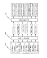
- Block diagram showing the configuration of the hand-holding motion detection means 201B Configuration diagram of a hearing aid equipped with a hand-holding motion detection device of Embodiment 4 of the present invention Schematic configuration diagram showing a configuration 1600 for realizing a hand-holding motion detection function
- the hand-holding operation is an operation that is generally performed by the user when the user wants to hear the sound in front more clearly, and is an operation in which the hand on the same side is applied to either the left or right ear. That is, the user turns the direction of the sound he wants to hear and turns the palm toward the direction of the sound he wants to hear.
- the position of the hand is behind the pinna, and in many cases, a part of the hand contacts the pinna.
- the hand is generally slightly rounded compared to a straightened state, and adjacent fingers other than the thumb are generally in contact with each other without being separated.
- FIG. 1 is a block diagram illustrating a configuration of a hand-holding motion detection device 1 according to the first embodiment.
- a hand-holding motion detection apparatus 1 shown in FIG. 1 includes omnidirectional microphones 101a and 101b, hand-holding motion detection means 201, hearing aid processing control means 202, directional sound collection means 203, and nonlinear amplification means 204. And a receiver 205.
- the hand-holding motion detection device 1 is incorporated in the body of the ear hole-mounted hearing aid 11 shown in FIG.
- FIG. 2 is a schematic configuration diagram illustrating a configuration of the ear hole-mounted hearing aid 11 including the hand-holding motion detection device 1 according to the present embodiment.
- the ear hole-mounted hearing aid 11 includes a directivity control mode changeover switch 12, a volume control unit 12, a non-directional microphone 101 a, 101 b that forms part of the hand-holding motion detection device 1, and a receiver 205.
- omnidirectional microphones 101a and 101b convert sound arriving at the microphones 101a and 101b into acoustic signals.
- the acoustic signals input from the microphones 101 a and 101 b are output to the hand-holding motion detection unit 201 and the directivity sound collection unit 203.
- the distance between the microphone 101a and the microphone 101b is set to 8 millimeters.
- the hand-holding motion detection means 201 performs a hand-holding motion determination process for determining whether or not the wearer of the ear hole-mounted hearing aid 11 is performing a hand-holding motion from the acoustic signals input from the microphones 101a and 101b. Details of the hand-holding motion determination process executed by the hand-holding motion detection unit 201 will be described later. The determination result by the hand-holding movement determination process is output to the hearing aid processing control unit 202.
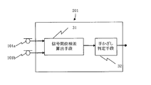
- FIG. 3 is a block diagram of the hand-holding motion detection means 201.
- the hand-holding motion detection unit 201 shown in FIG. 3 includes an inter-signal phase difference calculation unit 31 and a hand-holding motion determination unit 32.
- the hand-holding operation detection unit 201 has a function of monitoring the presence or absence of a phase difference between signals in a specific band and detecting a hand-holding state on the ear.
- the hand-holding motion detection unit 201 performs hand-holding motion determination processing, and details of the processing will be described later.
- the inter-signal phase difference calculating means 31 calculates the phase difference of the acoustic signals respectively input from the microphones 101a and 101b, and outputs the phase difference to the operation determining means 32 by hand.
- FIG. 4 is a block diagram showing the configuration of the inter-signal phase difference calculation means 31. As shown in FIG. As shown in FIG. 4,
- the inter-signal phase difference calculating means 31 includes a first bandpass filter means 41a, a second bandpass filter means 41b, a signal subtracting means 42a, a signal adding means 42b, Absolute value calculating means 43a, second absolute value calculating means 43b, first signal smoothing means 44a, second signal smoothing means 44b, and phase difference level calculating means 45.
- the first band-pass filter means 41a performs a process for limiting the signal band of the acoustic signal m1 input from the first microphone 101a, and the signal subtracting means 42a and the signal adding means for the acoustic signal m1 ′ whose signal band is limited. To 42b.
- the second band-pass filter means 41b performs processing for limiting the signal band of the acoustic signal m2 input from the second microphone 101b, and the signal subtracting means 42a and the signal adding means for the acoustic signal m2 ′ whose signal band is limited. To 42b.
- the signal subtracting means 42a performs a process of subtracting the acoustic signal m1 'input from the first bandpass filter means 41a and the acoustic signal m2' input from the second bandpass filter means 41b.
- the signal subtracting unit 42a outputs the subtracted acoustic signal (m1'-m2 ') to the first absolute value calculating unit 43a.
- the signal adding means 42b performs a process of adding the acoustic signal m1 'input from the first bandpass filter means 41a and the acoustic signal m2' input from the second bandpass filter means 41b. Then, the signal adding unit 42b outputs the added acoustic signal (m1 '+ m2') to the second absolute value calculating unit 43b.
- the first absolute value calculating unit 43a performs a process of calculating the absolute value
- the second absolute value calculating unit 43b performs a process of calculating the absolute value
- the first signal smoothing unit 44a performs a smoothing process on the absolute value
- input from the first absolute value calculating unit 43a, and the smoothed power signal A ( ⁇
- the second signal smoothing unit 44b performs a process of smoothing the absolute value
- input from the second absolute value calculating unit 43b, and the smoothed power signal B ( ⁇ )
- ⁇ represents a smoothing calculation.
- the phase difference level calculation means 45 performs a process of dividing the power signal A input from the first signal smoothing means 44a by the power signal B input from the second signal smoothing means 44b.
- the phase difference level calculation unit 45 calculates a phase difference level A / B that does not depend on the input sound pressure level, and outputs the phase difference level A / B to the subsequent hand-holding operation determination unit 32 as a parameter Cx.
- the hand-holding operation determining unit 32 determines whether or not the wearer of the ear hole-mounted hearing aid 11 is performing a hand-holding operation. A method for determining the hand-holding operation will be described later. Then, the determination result by the hand-holding movement determination process is output to the hearing aid processing control unit 202.
- Hearing aid processing control means 202 controls parameters of directivity sound collection means 203 and nonlinear amplification means 204 described later.
- the hearing aid processing control unit 202 controls the directivity sound collection unit 203 and the non-linear amplification unit 204 based on the determination result of the hand-holding motion determination process of the hand-holding motion detection unit 201.
- the directivity sound collection unit 203 performs a process of imparting directivity to the acoustic signals input from the microphones 101a and 101b under the control of the hearing aid processing control unit 202.
- the directivity-processed acoustic signal is output to the nonlinear amplification means 204.
- the non-linear amplification means 204 amplifies the acoustic signal subjected to the directivity processing by the directivity sound collection means 203 under the control of the hearing aid processing control means 202. Further, the non-linear amplification means 204 performs the process of multiplying the gain according to the level of the input signal so as to match the hearing characteristics of the hearing aid wearer under the control of the hearing aid processing control means 202, thereby obtaining the level of the output signal. To change. Then, the amplified acoustic signal is output to the receiver 205.
- the receiver 205 performs receiver directional signal processing on the acoustic signal amplified by the non-linear amplification means 204. Then, the acoustic signal processed by the receiver 205 is output as sound toward the ear canal of the wearer of the ear hole wearing type hearing aid 11.
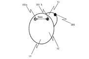
- FIG. 5 is a layout diagram for explaining a change in phase difference due to a hand-holding operation on the ear.
- the ear-hole-mounted hearing aid 11 provided with the hand-holding motion detection device 1 of the present embodiment includes two microphones.
- the user 51 is wearing the ear hole wearing type hearing aid 11 including the hand-holding motion detection device 1 of the present embodiment, and the user 51 wears the ear hole type wearing hearing aid 11 in his right ear 52.
- a speaker 53 as a sound source is disposed in front of the user 52.
- the hand-holding motion detection device 1 can measure a change in the phase difference between the outputs of the two microphones by a motion of the wearer of the ear hole-mounted hearing aid 11 holding his hand over his / her ear.
- FIG. 6 is a graph showing changes in the phase difference due to the hand-holding operation on the ear.
- the vertical axis represents the phase difference (rad).
- a curve C shows the microphone 101a in a state where the user 51 wears the ear hole-mounted hearing aid 11 in the right ear and does not hold his hand over the auricle (a state where both hands are lowered).
- the result of having measured the phase difference of 2-channel input of 101b is shown.
- curve A shows the two channels of the microphones 101a and 101b with the user 51 wearing the ear hole-mounted hearing aid 11 on the right ear and holding the right palm behind the auricle. The result of measuring the input phase difference is shown.
- Curve B shows the phase difference when two microphones are placed in front of and behind the sound source (speaker 53) in free space.
- the phase difference is 2 mm narrower than the actual microphone interval of 8 mm, the phase difference is a curve in a state where the hand is not held over the auricle indicated by the curve C at a frequency of 2 kHz or less. Can be approximated well.
- the hand-holding motion determination means 32 of the hand-holding motion detection device 1 determines the presence / absence of a hand-holding motion using the change in phase difference between the input sounds of two microphones generated by the hand-holding motion. .
- the hand-holding operation determination unit 32 determines whether or not there is a hand-holding operation based on the phase difference between the input sounds of two microphones.
- the first band-pass filter 41a and the second band-pass filter 41b perform signal interval by hand-holding operation for each of the acoustic signals m1 and m2 input from the first microphone 101a and the second microphone 101b.
- the frequency band is limited to a band where a change in phase difference is remarkable.
- the frequency band for which band limitation is performed by the first band-pass filter 41a and the second band-pass filter 41b is determined based on the measurement result shown by the curve A in FIG. In this embodiment, it is set to 1 kHz to 3 kHz.
- the difference between the signal m1 'and the signal m2' is calculated.
- the phase difference approaches zero, and the subtraction result also approaches zero.
- the subtraction result does not become zero but the remaining signal remains.
- the magnitude of the unerased signal depends on the arrival time difference, that is, the arrival direction of the sound waves for the two microphones.
- the signal m1 ′ and the signal m2 ′ have a phase difference associated with the sound speed corresponding to the distance between the microphones, so that a signal accompanying the sound wave is observed in the output signal of the signal subtracting means 42a. Therefore, it is possible to detect the difference from the fact that the phase difference becomes close to zero after the hand-holding operation.
- the signal adding means 42b calculates the addition of the signal m1 ′ and the signal m2 ′, obtains an output signal proportional to the sound pressure level of the sound wave arriving at the microphone, and obtains the signal level from the signal subtracting means 42a. It is provided for normalization.
- the acoustic signal (m1′ ⁇ m2 ′) from the signal subtracting means 42a has been described above that the output is close to zero in the hand-held state. There is an unerased residue. Therefore, the output signal level from the signal subtracting means 42a in the hand-held state changes depending on the original level of the incoming sound wave.
- the sound pressure level of the sound wave arriving at the first microphone 101a and the second microphone 101b It is necessary to convert the parameter Cx that does not depend on.
- the first absolute value calculating means 43a and the second absolute value calculating means 43b are for obtaining the sound pressure level arriving at the first microphone 101a and the second microphone 101b and the sound pressure level of the unerased signal.
- of the output signal of the signal adding means 42b are calculated.
- the first signal smoothing means 44a and the second signal smoothing means 44b for example, with respect to the outputs from the first absolute value calculating means 43a and the second absolute value calculating means 43b, for example, a first-order integrator. Is used to calculate the power signal A and the power signal B, which are indicators of the sound pressure level.
- the phase difference level calculation means 45 adds the input signal to the power signal A obtained by subtracting the input signals input from the two microphones, which are the first microphone 101a and the second microphone 101b. By dividing by the obtained power signal B, a phase difference level independent of the input sound pressure level is calculated and output as a parameter Cx.
- the inter-signal phase difference calculating means 31 receives input signals from the two microphones by a hand-holding operation by a person wearing the ear hole-mounted hearing aid 11 including the hand-holding motion detection device 1 of the present embodiment. It can be extracted that the phase difference between the signals becomes zero in a specific frequency band without depending on the input sound pressure level to the two microphones.
- the hand-holding motion determination unit 32 When the parameter Cx input from the phase difference level calculation unit 45 continues for a certain period of time, the hand-holding motion determination unit 32 is provided with the ear hole-equipped hearing aid provided with the hand-holding motion detection device 1. It is determined that 11 wearers are performing a hand-holding operation. Further, the hand-holding movement determination means 32, when the parameter Cx input from the phase difference level calculation means 45 does not continue below a certain threshold value for a certain period of time, the earpiece-mounted hearing aid 11 provided with the hand-holding movement detection device 1. It is determined that the wearer is not holding the hand. As described above, the hand-holding motion determination process of the hand-holding motion detection means 201 is performed.
- the hand-holding motion determination unit 32 is an ear hole wearing type equipped with the hand-holding motion detection device 1 when the state in which the parameter Cx input from the phase difference level calculation unit 45 is a predetermined threshold value or less continues for a certain period of time. It is determined that the wearer of the hearing aid 11 is performing a hand-holding operation, and further, the length of time for which the hand-holding is continued, that is, the length of the hand-holding is calculated.
- the hand-holding motion determination unit 32 repeats the state in which the hand-holding operation is performed within a predetermined time and the state in which the hand-holding operation is not performed, the number of hand-holding operations within the predetermined time, that is, Calculate the frequency of hand-holding.
- the hearing aid processing control means 202 controls the directional sound collection means 203 using the result of the hand-holding movement determination process obtained as described above, so that the user can hold the ear hole-mounted hearing aid 11 with the hand holding the hand.
- the sound to be heard can be brought closer to a more preferable way of hearing.
- the user 51 wears the ear hole-equipped hearing aid 11 on the right ear and the right palm is held behind the auricle. The sound becomes more emphasized and can be heard.
- FIG. 7 is a block diagram showing the configuration of the directivity sound collection means 203.
- the directivity sound collection unit 203 illustrated in FIG. 7 includes delay devices 701a and 701b, variable amplifiers 702a and 702b, an adder 703, and an equalizer 704.
- Delay devices 701a and 701b perform a process of giving a predetermined delay amount to each of the acoustic signals input from the microphones 101a and 101b. Then, the delayed acoustic signals are output to the variable amplifiers 702a and 702b, respectively.
- variable amplifiers 702a and 702b perform gain processing for multiplying each of the delayed acoustic signals by a predetermined gain value.
- the gain-processed acoustic signal is output to the adder 703.
- the adder 703 performs a process of adding the two gain-processed acoustic signals and outputs the result to the equalizer 704.
- the settings of the delay devices 701a and 701b and the variable amplifiers 702a and 702b are determined by the shape of directivity formed by the microphones 101a and 101b. For example, when a directional blind spot is formed in the direction 707, first, the time difference ⁇ corresponding to the time during which the sound wave propagates the distance d between the microphones 101a and 101b is calculated by (Equation 1).
- Equation 1 the time difference ⁇ corresponding to the time during which the sound wave propagates the distance d between the microphones 101a and 101b is calculated by (Equation 1).
- c is the speed of sound.
- the delay time in the delay device 701b is set so as to be larger than the delay time in the delay device 701a. Further, +1 is set as a gain value to be multiplied by the input in the variable amplifier 702a, and ⁇ 1 is set as a gain value to be multiplied by the input in the variable amplifier 702b.
- the sound wave arriving from the direction 707 is delayed by ⁇ from the time when it arrives at the microphone 101a than the time when it arrives at the microphone 101b.
- the delay time of the delay device 701b is set larger than the delay time of 701a.
- the variable amplifier 702a outputs the signal while maintaining the phase, and the variable amplifier 702b outputs the signal with the phase inverted.
- the adder 703 adds the two waveforms output from the variable amplifier 702a and the variable amplifier 702b. This corresponds to subtracting the outputs of the delay devices 701 a and 701 b, and both are canceled out, and a directivity blind spot can be formed in the direction 707 at the output of the adder 703.
- the time difference between the microphones 101a and 101b becomes smaller than ⁇ , so that a time difference occurs at the outputs of the delay units 701a and 701b, and the output of the adder 703 is not completely canceled out. A residual component is generated.
- the power of this residual component increases as the arrival direction of the sound wave deviates from the direction 707 and becomes maximum when the direction is the direction 706. In this way, directivity having a blind spot in the direction 707 is formed.
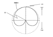
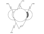
- FIG. 8 shows a schematic diagram of directivity when directivity processing is performed by the directivity sound collection means 203 shown in FIG.
- the sound output from the sound source (speaker 53) is collected by the hand-holding motion detection device 1 worn by the user 52, the sound is directed in a direction corresponding to the direction 707 as indicated by the solid line M.
- a directivity is formed so that a blind spot is formed and sensitivity in a direction corresponding to the direction 706 is increased.
- the frequency characteristics of the acoustic signal output from the adder 703 when the sound wave arrives from the direction 706 that forms the directivity as described above and has high sensitivity, the frequency is higher than that in the non-directional case. The lower the sensitivity, the lower the sensitivity.
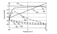
- FIG. 9 shows sensitivity frequency characteristics and circuit noise level frequency characteristics.
- the horizontal axis in FIG. 9 is the frequency characteristic, and the vertical axis is the relative value of the amplitude.
- the sensitivity has a theoretically flat frequency characteristic as indicated by a solid line 901 in FIG.
- the directivity as shown in FIG. 8 is formed, the sensitivity decreases as the frequency decreases as shown by the broken line 902 in FIG. This is because the phase difference between the outputs of the delay devices 701a and 701b becomes smaller as the frequency becomes lower, and the output power of the adder 703 becomes smaller.
- the directivity sound collection unit 203 of the hand-holding motion detection device 1 corrects the frequency characteristics based on the control of the hearing aid processing control unit 202. Perform the process.
- An equalizer 704 shown in FIG. 7 performs a process of correcting the frequency characteristic of the output signal of the adder 703. The frequency characteristics are corrected by (1) making the frequency characteristics of sensitivity to the direction 706 close to flat as shown in FIG. 7 and (2) not amplifying the circuit noise generated inside the microphone. It is necessary to determine the characteristics of the equalizer 704 in consideration.
- the ECM (Electret Condenser Microphone) device used in the ear hole-mounted hearing aid 11 of the present embodiment has a circuit noise as indicated by a one-dot chain line 905 shown in FIG.
- the power of circuit noise generally has a characteristic that it becomes larger at lower frequencies. Therefore, when the directivity as shown in FIG. 8 is formed, the waveform of the circuit noise of the microphones 101a and 101b is considered to be independent from each other. For this reason, in the output of the adder 703 in FIG. 7, the circuit noise level theoretically rises by 3 dB as compared with the case of the microphone alone, and has a frequency characteristic as shown by a one-dot chain line 906 shown in FIG.
- the frequency characteristic of the equalizer 704 in the present embodiment is corrected so as to flatten the sensitivity in the direction 706 shown in FIG. 7, the gain increases as the frequency decreases. As a result, the circuit noise level of the output of the equalizer 704 becomes large especially in a low frequency range.
- the processing for correcting the sensitivity in the direction 706 shown in FIG. gives the equalizer 704 characteristics as shown by a two-dot chain line 903 in FIG.
- the sensitivity with respect to the direction 706 shown in FIG. 7 is corrected as indicated by a solid line 904 shown in FIG. 9, but compared with the solid line 901 shown in FIG. It can be seen that is decreasing.
- circuit noise level at the output of the equalizer 704 is the sum of the circuit noise level 906 at the output of the adder 703 and the frequency characteristic 903 of the equalizer 704, and rises particularly in a low frequency range. The noise level tends to increase.
- processing for emphasizing the sound in front of the hearing aid wearer is often performed by forming directivity as shown in FIG.
- directivity formation it is assumed that there is a time difference between sound waves that arrive at two microphones in principle.
- the time difference becomes zero, so that the desired directivity cannot be formed, and in particular, the frequency is omnidirectional in the vicinity of 1 kHz to 3 kHz. It becomes directivity close to sex. In this case, not only becomes omnidirectional, but also the circuit noise level rises, so that the wearer of the hearing aid 11 not only has the effect of enhancing the forward sound, but also the circuit noise can be heard loudly. become.
- the directivity sound collection unit 203 is omnidirectional in the hearing aid processing control unit 202. Control is performed as follows. That is, when the directivity is formed, the gain value of the variable amplifier 702b is -1, but when this is set to 0, only the output of the variable amplifier 702a is input to the adder 703. , Become omnidirectional.
- the equalizer 704 does not require the characteristic like the two-dot chain line 903 in FIG. 9 that is necessary when the directivity is formed, and can provide a characteristic closer to flatness. As a result, the noise level can be kept low.
- the directivity sound pickup is performed as described above. It is possible to change to omnidirectionality by changing the parameter of the means 203. As a result, hearing aids with low noise can be performed for the hearing aid wearer.
- the hand-holding motion detection unit 201 determines that the hand-holding motion is being performed as described above. If it is determined that the cover is not held, the parameters of the directivity sound collection unit 203 are returned to the normal state.
- the front of the hearing aid wearer is based on the phase difference between the signals input from the two microphones according to the hand-holding motion of the wearer of the hearing aid 11. Can be emphasized.
- the hand-holding motion detection device 1 can bring the hearing aid to the hearing aid wearer closer to the preferred hearing.
- the nonlinear amplification means 204 controls the output level by multiplying the gain according to the input level so as to match the hearing characteristics of the hearing aid wearer under the control of the hearing aid processing control means 202.
- FIG. 10 shows an example of amplification characteristics of nonlinear amplification.
- the horizontal axis in the figure is the input level (dB), and the vertical axis is the output level (dB).
- the input level indicated as “Compression” is medium
- the so-called limiter process that does not change the output level even when the input level increases, causes loudness and discomfort to the user. Is reduced.
- the amplification factor is greatly reduced when the input level is reduced, so that a very small sound that is normally considered unnecessary for the hearing aid wearer, It amplifies circuit noise and prevents it from being heard.
- the nonlinear amplification means 204 has sufficient characteristics shown by a straight line 1002 in FIG. 10 (broken line in the figure).
- the output level is reduced even though the sound that the hearing aid wearer wants to hear, and the hearing aid wearer does not hear the sound that the hearing aid wearer originally wants to hear. It becomes difficult to listen.
- the characteristic of the nonlinear amplification unit 204 is, for example, shown in FIG.
- the hearing aid processing control unit 202 controls the non-linear amplification unit 204 so as to change the characteristic shown by the broken line 1002 to the characteristic shown by the solid line 1001 in FIG.
- a method for increasing the amplification factor there is a method of increasing the amplification factor at a time when a hand-holding motion is detected in the hand-holding motion determination process of the hand-holding motion detection means 201.
- the amplification factor is changed in accordance with the hand-holding time length calculated by the hand-holding motion detection means 201 and the gain is increased as the hand-holding time length increases.
- the amplification factor is changed in accordance with the number of handshakes calculated by the hand-holding motion detection means 201, and the gain is increased as the number of handshaking times increases.
- the hand-holding motion detecting unit 201 determines that the hand-holding motion is performed as described above, the hand-holding motion detection is performed in a state where the gain of the characteristic of the nonlinear amplifying unit 204 is changed to be increased. If the means 201 determines that the hand is not held up, the amplification factor of the characteristic of the nonlinear amplification means 204 is returned to the normal state.
- the hand-holding motion detection apparatus 1 in the present embodiment the levels of signals input from the two microphones are nonlinearly amplified in accordance with the hand-holding motion of the wearer of the hearing aid 11. For this reason, the hand-holding movement detection device 1 can make it easy for the wearer of the hearing aid 11 to hear even a small sound that is difficult for the wearer of the hearing aid 11 to hear in normal characteristics.
- the hand-holding motion detection device 1 in the present embodiment the hand-holding motion is detected without providing an additional sensor by adopting a configuration in which determination is performed by processing of input signals input from two microphones. can do. Further, since no additional sensor is provided, it is possible to detect a hand-holding operation without increasing the size of the hearing aid. Further, it is possible to change the control of the hearing aid according to the hand-holding operation.
- the present invention can be similarly applied even when provided with three or more microphones.
- input signals input from a plurality of microphones provided for hearing aid processing it is possible to detect a hand-holding action on the ear without installing an additional sensor.
- control of the hearing aid in accordance with the intention of the user to hear the sound ahead is enabled by the gesture without operating the small switch of the hearing aid that is difficult to operate at the time of wearing.
- FIG. 11 is a block diagram illustrating a configuration of the hand-holding motion detection device 2 according to the second embodiment.
- the difference between the hand-holding motion detection device 2 of the second embodiment and the hand-holding motion detection device 1 of the first embodiment is the configuration of the hand-holding motion detection means.
- the second embodiment is the same as the first embodiment, and in FIG. 11, the same reference numerals are given to the components common to FIG. 1.
- the configuration other than the hand-holding motion detection unit is the same as that of the first embodiment, and thus detailed description thereof is omitted.
- the hand-holding motion detection device 2 is incorporated in the main body of the ear hole-mounted hearing aid 11 shown in FIG.
- the hand-holding motion detection device 2 of the second embodiment includes omnidirectional microphones 101a and 101b, hand-holding motion detection means 201A, hearing aid processing control means 202, and directional sound collection. Means 203, non-linear amplification means 204, and receiver 205 are provided.
- FIG. 12 is a block diagram showing the configuration of the hand-holding motion detection means 201A.
- the hand-holding motion detection unit 201A illustrated in FIG. 12 includes a spectrum change amount extraction unit 1101 and a hand-holding motion determination unit 1102.
- the spectrum change amount extraction unit 1101 extracts the change amount of the spectrum power included in the acoustic signals input from the microphones 101a and 101b. With reference to FIG. 13, the configuration of the spectrum change amount extraction unit 1101 will be described.
- FIG. 13 is a block diagram showing a configuration of the spectrum change amount extraction unit 1101.
- the spectrum change amount extraction unit 1101 illustrated in FIG. 13 includes a filter processing unit 1301, a band power calculation processing unit 1302, and a time difference calculation unit 1304.
- the filter processing means 1301 performs processing for dividing the acoustic signals input from the microphones 101a and 101b into six frequency bands, respectively.
- the six frequency bands are, for example, an LPF-band 1 representing a frequency band of 800 Hz or less, a BPF-band 2 representing a frequency band of 800 Hz to 1 kHz, and a frequency of 1 kHz to 2 kHz or less.
- BPF-band 3 representing a band
- BPF band 4 representing a frequency band from 2 kHz to 3 kHz
- BPF band 5 representing a frequency band from 3 kHz to 4 kHz
- HPF-band 6 representing a frequency band from 4 kHz to 4 kHz. .
- Band power calculation processing means 1302 performs processing for calculating power for each band for the acoustic signal whose frequency band is divided by the filter processing means 1301.
- the power of each of the bands 1, 2, 3, 4, 5, 6 of the acoustic signal input from the microphone 101a is V1a (t), V2a (t), V3a (t), Let V4a (t), V5a (t), and V6a (t).
- the power of each band 1, 2, 3, 4, 5, 6 of the acoustic signal input from the microphone 101b is V1b (t), V2b (t), V3b (t), V4b (t), respectively. , V5b (t), V6b (t).
- Each power is a power value for each time.
- the time difference calculation means 1304 includes power values V1a (t1) to V6a (t1) and V1b (t1) to V6b (t1) for each band calculated at time t1, and a band at time t0 a predetermined time before time t1.
- Spectral power change ⁇ VNa ( VNa (t1) ⁇ VNa) for each microphone, for each band, and for each time based on the difference from another power value V1a (t0) to V6a (t0) and V1b (t0) to V6b (t0) (T0))
- ⁇ VNb ( VNb (t1) ⁇ VNb (t0)) (N is a natural number from 1 to 6).
- the calculated spectral power change amounts ⁇ VNa and ⁇ VNb (N is a natural number from 1 to 6) are handed over and output to the motion determination means.
- the hand-holding movement determination unit 1102 determines whether or not there is a hand-holding movement based on the spectrum power change amounts ⁇ VNa and ⁇ VNb input from the time difference calculation unit 1304. For example, the hand-holding motion determination unit 1102 divides the frequency band used for determining whether or not the hand-holding motion is present into three regions, a low region, a middle region, and a high region. Next, the hand-holding movement determination means 1102 includes a time change of spectrum power in the low frequency range without power change due to the hand-holding action, and a time change of spectrum power in the middle band where there is a power change due to the hand-holding action. Based on the two bands, the presence / absence of a hand-hold operation is determined.
- a time zone in which the spectral power changes little with time is specified in a low range where the power does not change due to a hand-holding operation.
- the hand-holding movement determination unit 1102 pays attention to the spectrum change amount from the time t0 to the time t1 based on the spectrum change amounts ⁇ VNa and ⁇ VNb (N is a natural number from 1 to 6).
- the hand-holding operation determination unit 1102 has the sum of the spectral power change amounts ⁇ V1a and ⁇ V1b of the LPF-band 1 shown in FIG. 13 equal to or smaller than the threshold (Dth1) and the BPF-band 3 shown in FIG. If the sum of the spectral power changes ⁇ V3a and ⁇ V3b and the BPF-band 4 spectral power changes ⁇ V4a and ⁇ V4b shown in FIG. 13 is equal to or greater than the threshold value (Dth2), it can be determined that there is a hand-hold operation. .
- the hand-holding motion determination means 1102 detects a motion of the wearer of the earhole-mounted hearing aid 11 equipped with the hand-holding motion detection device 1 covering the auricle with a hand.
- the power of the sound input from the outside to the microphones 101a and 101b is greatly reduced in a short time, and compared with the power before a certain time. If the state where the power is low continues for a certain period of time, the wearer determines that the operation covers the auricle.
- the entire frequency band may be used as the band for determining the power change, but the low frequency band may not be reduced depending on how the wearer's auricle is covered.
- Preferably at least part of the 1 to 4 kHz band where it is generally not susceptible to the wearer's covering of the pinna and is generally expected to have a certain amount of ambient sound Is appropriate.
- time t0 is provided at 5 points at 1 second intervals, and the total value of the spectrum change amount is Dth2 or more in all of the time points. A little time width may be given in the determination. Since the external spectrum is constantly changing, such as the audio spectrum always changes depending on the phoneme, just looking at the change in the spectrum power in the entire frequency band, it may have changed due to hand-holding movement, It is difficult to judge whether it has changed. However, by using this method, it is possible to detect a hand-holding action using a temporal change in spectrum power.
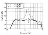
- FIG. 14 is a diagram showing the time average of the spectrum power used by the hand-holding motion determining means 1102 for determining whether or not the hand-holding motion is present. It is assumed that the time average of the spectral power shown in FIG. 14 is obtained with the arrangement shown in FIG. 5 as in the first embodiment. That is, the male voice output from the speaker 53 is two microphones 101a and 101b of the ear hole-mounted hearing aid 11 having the hand-holding motion detection device 2 mounted on the right ear 52 of the user 51 in the acoustic room. It is assumed that the signal is input to the hand-holding motion detection device 2 via.
- FIG. 14 shows the result of comparative measurement of the long-term average of the two-channel input spectrum power with and without the microphones 101a and 101b.
- the horizontal axis represents the logarithm of frequency, and the vertical axis represents the spectral power.
- the broken line F in FIG. 14 shows the measurement results when the hand is held over the auricle, and the broken line D in FIG. 14 shows the measurement result when the hand is held down.
- the difference due to the presence or absence of the hand-holding operation on the auricle appears remarkably as an increase in power from 1 kHz to 3 kHz, and there is almost no difference below 800 Hz.
- the palm is not suitable for the low frequency band that tends to go around and the high frequency band that tends to attenuate. This is considered to be due to the fact that the influence of the presence of noise is small and the intermediate frequency band is most affected.
- the parameters of the directivity sound collection unit 203 or the nonlinear amplification unit 204 are set to normal.
- the parameter is returned to the normal state.
- the hand-holding motion detecting unit 201 determines that the hand-holding motion is being performed
- the hand-holding motion determining unit 1102 receives the ear while the hand-holding motion determining unit 1102 is changed so as to increase the amplification factor of the characteristic.
- the amplification factor of the characteristic of the nonlinear amplification means 204 is returned to the normal state.
- the hand-holding motion detection device 2 in the present embodiment it is possible to detect a hand-holding motion based on a time change of power in a specific frequency band with respect to signals input from two microphones. .
- the hand-holding motion detection device 2 in the present embodiment the hand-holding motion is detected without providing an additional sensor by adopting a configuration in which determination is made by processing input signals input from two microphones. can do.
- the case where the spectrum input from the microphone is divided into six bands is illustrated, but it is sufficient that the low-frequency spectrum and the high-frequency spectrum can be distinguished. If the frequency bands are divided, the same effect can be obtained even if the number of divided frequency bands is more or less than six.
- FIG. 15 is a block diagram illustrating a configuration of the hand-holding motion detection device 3 according to the third embodiment.
- the difference between the hand-holding motion detection device 3 of the third embodiment and the hand-holding motion detection device 1 of the first embodiment is the configuration of the hand-holding motion detection means. Except for this point, the second embodiment is the same as the first embodiment.
- the same reference numerals are given to the components common to FIG. 1.
- the hand-holding motion detection device 3 is incorporated in the main body of the ear hole-mounted hearing aid 11 shown in FIG.
- the hand-holding motion detection device 3 includes omnidirectional microphones 101a and 101b, hand-holding motion detection means 201B, hearing aid processing control means 202, and directional sound collection. Means 203, non-linear amplification means 204, and receiver 205 are provided.
- FIG. 16 is a block diagram showing the configuration of the hand-holding motion detection means 201B.
- the hand-holding motion detection means 201B shown in FIG. 16 includes a signal phase difference calculation means 31, a spectrum change amount extraction means 1101, and a hand-holding motion determination means 1401.
- the operations of the inter-signal phase difference calculating unit 31 and the spectrum change amount extracting unit 1101 are the same as those described in the first embodiment and the second embodiment, respectively, and detailed description thereof is omitted.
- the hand-holding operation determination unit 1401 determines that there is a hand-holding operation when both determination conditions are satisfied, using both the inter-signal phase difference calculation unit 31 and the output of the spectrum change amount extraction unit 1101. That is, it is confirmed whether or not the time during which the inter-signal phase difference obtained by the inter-signal phase difference calculating unit 31 is equal to or less than the threshold (Cth) has continued for a time equal to or greater than the threshold (Tth).
- the hand-holding motion detection device 3 in the present embodiment in the specific frequency band of the signals input from the two microphones, the time change of the power and the phase difference of the signals input from the two microphones. Based on the change over time, the presence / absence of a hand-holding action is determined.
- the hand-holding motion detection device 3 in the present embodiment the hand-holding motion is detected without providing an additional sensor by adopting a configuration in which determination is made by processing of input signals input from two microphones. can do. Further, since no additional sensor is provided, it is possible to detect a hand-holding operation without increasing the size of the hearing aid.
- FIG. 17 is a configuration diagram of a hand-holding motion detection system including a hand-holding motion detection device in Embodiment 4 of the present invention.
- a hearing aid equipped with the hand-holding motion detection device shown in FIG. 17 includes a right ear-side ear hole-mounted hearing aid 1502, a left ear-side ear hole-mounted hearing aid 1503, and a communication means 1504.
- a user 1501 wears an ear hole-mounted hearing aid 1502 in the right ear and a left ear also has an ear hole-mounted hearing aid 1503.
- the ear hole-mounted hearing aid 1502 and the left ear-side ear hole-mounted hearing aid 1503 are the same as the ear hole-mounted hearing aid 11 provided with the hand-holding motion detection device 1 described in Embodiment 1 and the communication means 1504. Since it is the same structure, the detailed description is abbreviate
- the communication means 1504 is a wireless communication means for performing wireless communication between the right ear-side ear hole-mounted hearing aid 1502 and the left ear-side ear hole-mounted hearing aid 1503, and here, electromagnetic induction is used.
- the ear-hole-mounted hearing aid 1502 and the left-ear-side ear-hole-mounted hearing aid 1503 receive a hand-holding motion detection notification from one hearing aid or a hand-holding motion detection notification to the other hearing aid via the communication means 1504. Can be sent.
- the ear-hole-mounted hearing aid 1502 when the hand-holding operation is detected with the right ear-side hearing hole-mounted hearing aid 1502, the ear-hole-mounted hearing aid 1502 is placed over the left ear-side ear hole-mounted hearing aid 1503 via the communication unit 1504. Notify that motion has been detected. Then, the left ear-side ear-hole type hearing aid 1503 that has received the notification of detection of hand-holding operation performs control to maintain the directional signal processing in the current state and increase the volume output from the receiver 205. For example, the ear hole-mounted hearing aid 1503 increases the volume output from the receiver 205 by 1.2 times. The numerical value for increasing the volume may be changed according to another index such as the user's hearing ability or ambient noise level.
- the hearing aid device including the hand-holding motion detection device it is possible to determine by processing of the input signals input from the two microphones without providing an additional sensor. A hand-holding action can be detected. Furthermore, in a hearing aid device in which both ears cooperate with each other, when a hand-holding operation is detected on one side, the control change of the hearing aid can be performed on both the left and right hearing aid terminals.
- the hand-holding motion detection devices of Embodiments 1 to 4 described above detect hand-holding motions to the ear using input signals input from two or more microphones of the hearing aid, and control determination of the hearing aid Functions as a detection means.
- the above-described hand-holding motion detection devices of Embodiments 1 to 4 are used in a hearing aid that has two or more microphones and performs directional signal processing by detecting a hand-holding motion to the ear. It is possible to detect a person holding his hand over his ear without installing an additional sensor and change the control.
- the directivity signal processing that takes the input difference is stopped to make it non-directional, and the forward directivity of the input sound is left to reflection by the hand, and the outputs of multiple microphones are added together and further output
- the sound pressure can be increased. This makes it possible to meet the desire of “I want to hear more of the previous sound”, which is generally thought to be when the user holds his / her hand on the ear without operating the small switch on the hearing aid. It becomes possible to change the control of the hearing aid.
- the hearing aid device and the hearing aid method according to the present invention have an effect that the directivity processing or amplification processing by the hearing aid can be controlled by the user's hand-holding operation so as to match the user's intuition, and are useful as a hearing aid. is there.
Landscapes
- Health & Medical Sciences (AREA)
- General Health & Medical Sciences (AREA)
- Neurosurgery (AREA)
- Otolaryngology (AREA)
- Physics & Mathematics (AREA)
- Engineering & Computer Science (AREA)
- Acoustics & Sound (AREA)
- Signal Processing (AREA)
- Circuit For Audible Band Transducer (AREA)
Abstract
Description
図18は、特許文献1に開示されている手かざし動作検出機能を実現する構成1600を示す概略構成図である。図18に示す構成では、赤外線距離センサ1611が近接する物体との距離を計測する。そして、図18に示すように、使用者の手のひら1612と赤外線距離センサ1611との距離δが一定の範囲内である場合に、手かざし動作を検出することができる。
よって「位相差が妥当な範囲から逸脱した場合」を検出することができれば、耳に手をかざした場合などの指向性信号処理が意図通り機能しなくなる場合を検出することが可能となる。
本発明の実施の形態1は、位相差の時間変化を用いた手かざし動作検出方法について、図1から図10を参照して、説明する。
図1は、実施の形態1における手かざし動作検出装置1の構成を示すブロック図である。図1に示す手かざし動作検出装置1は、無指向型のマイクロホン101a、101bと、手かざし動作検出手段201と、補聴処理制御手段202と、指向性収音手段203と、非線形増幅手段204と、レシーバ205と、を備える。
そして、手かざし動作判定処理による判定結果は、補聴処制御手段202に出力される。
以下の説明は、本実施の形態の手かざし動作検出装置1の動作についてである。
本実施の形態の手かざし動作検出装置1では、2つのマイクロホンの入力信号から算出した位相差の変化に基づき、耳穴装着型補聴器11の装着者が手かざし動作を行っているか否かを判定するが、その原理について、図5を参照して説明する。図5は、耳への手かざし動作による位相差の変化を説明するための配置図である。
本実施形態の手かざし動作検出装置1の手かざし動作判定手段32は、手かざし動作によって生じる、2つのマイクロホンの入力音が有する位相差の変化を利用して、手かざし動作の有無を判定する。以下、手かざし動作判定手段32が、2つのマイクロホンの入力音が有する位相差に基づく手かざし動作の有無を判定する方法について、説明する。ここでは、耳に手かざし動作した場合に特定の周波数帯域において、2つのマイクロホン101a、101bの間の位相差が、音波の到来方向に関わらずゼロに近づくことに着目している。
従って、到来する音波が有する元々のレベル次第で、手かざし状態における信号減算手段42aからの出力信号レベルは変化する。信号減算手段42aからの出力信号(m1’-m2’)を基に閾値判定によって手かざし状態を検出する為には、第1のマイクロホン101a及び第2のマイクロホン101bに到来する音波の音圧レベルに依存しないパラメータCxに変換する必要がある。
以上のように得られた手かざし動作判定処理の結果を用いて、補聴処理制御手段202が指向性収音手段203を制御することで、ユーザが手かざしの状態で、耳穴装着型補聴器11で聞く音をより好ましい聞こえ方に近づけることができる。本実施形態の場合、図6の曲線Aで示す測定結果において、使用者51が耳穴装着型補聴器11を右耳に装着し、右手のひらを耳介後方にかざした状態なので、使用者の前方の音がより強調されて聞こえるようになる。

以下の説明は、手かざし動作検出のもう1つの利用方法として、手かざし動作検出装置1を具備する補聴器11の増幅比率を制御する場合についてである。図2において、非線形増幅手段204は補聴処理制御手段202の制御により、補聴器装着者の聴覚特性に合致するよう、入力レベルに応じてゲインを乗算することにより出力レベルの制御を行う。
補聴処理のために備えられた複数のマイクロホンから入力される入力信号を用いて、追加のセンサ設置なしにて、耳への手かざし動作を検出することが可能となる。また、使用者が前方の音をより聞きたいという意図に沿った補聴器の制御が、装着時に操作することが困難な補聴器が有する小さいスイッチを操作することなく、ジェスチャにより可能となる。
本発明の第2の実施形態として、スペクトルパワの時間変化を用いた手かざし動作検出方法について、図11~図13を参照して、説明する。
図11は、第2の実施形態の手かざし動作検出装置2の構成を示すブロック図である。第2の実施形態の手かざし動作検出装置2が第1の実施形態の手かざし動作検出装置1と異なる点は、手かざし動作検出手段の構成である。この点以外は第1の実施形態と同様であり、図11において、図1と共通する構成要素には同じ参照符号が付されている。なお、本実施形態では、手かざし動作検出手段以外の構成は、第1の実施形態と同様のため、その詳細な説明を省略する。
そして、算出したスペクトルパワ変化量ΔVNa、ΔVNb(Nは1から6の自然数)を手かざし動作判定手段に出力する。
すなわち、手かざし動作検出手段201において手かざし動作を行っていると判定された後、指向性収音手段203のパラメータが変更されている状態において、手かざし動作判定手段1102において耳介を覆う動作をしていると判定された場合には、指向性収音手段203のパラメータを通常の状態に復帰させる。また、手かざし動作検出手段201において手かざし動作を行っていると判定された後、非線形増幅手段204の特性の増幅率を高めるように変更されている状態において、手かざし動作判定手段1102において耳介を覆う動作をしていると判定された場合には、非線形増幅手段204の特性の増幅率を通常の状態に復帰させる。
上述の実施の形態1及び実施の形態2にて例示したように、2つのマイクロホンから入力される信号が有する位相差の時間変化、スペクトルパワの時間変化、どちらを用いても耳への手かざし動作の有無の判定を行うことが可能であるが、さらに手かざし動作の有無の判定について確度を挙げるためには、併用すると効果的である。
図17は、本発明の実施の形態4において、手かざし動作検出装置を備えた手かざし動作検出システムの構成図である。図17に示す手かざし動作検出装置を備えた補聴装置は、右耳側の耳穴装着型補聴器1502と、左耳側の耳穴装着型補聴器1503と、通信手段1504と、を備える。使用者1501は、右耳に耳穴装着型補聴器1502を、左耳も耳穴装着型補聴器1503を装着している。
11 耳穴装着型補聴器本体
12 指向性制御モード切り替えスイッチ
13 ボリュームスイッチ
31 信号間位相差算出手段
32 手かざし動作判定手段
41a、41b 帯域通過フィルタ手段
42a 信号減算手段
42b 信号加算手段
43a、43b 絶対値算出手段
44a、44b 平滑化手段
45 位相差レベル算出手段
51 補聴器の使用者
52 補聴器使用者の右耳
53 スピーカ
201 手かざし動作検出手段
202 補聴処理制御手段
203 指向性収音手段
204 非線形増幅手段
205 レシーバ
701a、701b 遅延器
702a、702b 可変増幅器
703 加算器
704 イコライザ
1101 スペクトル変化量抽出手段
1102 手かざし動作判定手段
1301 フィルタ処理手段
1302 帯域パワ算出処理手段
1304 時間差分算出手段
1502 右耳側の耳穴装着型補聴器
1503 左耳側の耳穴装着型補聴器
1504 通信手段
1611 赤外線距離センサ
1713a、1713b 周波数分析手段
1714 位相差スペクトル算出手段
1715 時間的変化検出手段
1716 空間内変化判定手段
Claims (8)
- 収音した音を音響信号に変換する複数のマイクロホンと、
前記複数のマイクロホンのうち、第1のマイクロホンにおいて変換された第1の音響信号と、第2のマイクロホンにおいて変換された第2の音響信号との位相差を算出する信号間位相差算出部と、
前記位相差が第1の閾値以下である状態が第1の時間継続するか否かを判定する手かざし判定部と、
前記第1のマイクロホンから取得された前記第1の音響信号および前記第2のマイクロホンから取得された前記第2の音響信号に対して、収音方向の感度を制御する感度周波数特性を重畳して、音響信号の周波数特性を制御することによって、出力信号を生成する指向性収音部と、
前記指向性収音部から取得された前記出力信号の信号レベルを制御する非線形増幅部と、
前記手かざし判定部において、前記位相差が前記第1の閾値以下である状態が前記第1の時間継続すると判定された場合に、前記感度周波数特性または前記音響信号の周波数特性のうち少なくとも何れか一方を無指向性とするように前記指向性収音部を制御し、前記取得された音響信号の信号レベルを増幅するように前記非線形増幅部を制御する補聴処理制御部と、
を備える補聴装置。 - 前記第1のマイクロホンから取得された前記第1の音響信号および前記第2のマイクロホンから取得された前記第2の音響信号を、第1の周波数帯域と、前記第1の周波数帯域よりも高域である第2の周波数帯域との少なくとも2つの周波数帯域に分割し、前記第1の周波数帯域における前記第1の音響信号および前記第2の音響信号の第2の時間における第1のスペクトルパワ変化量、並びに、前記第2の周波数帯域における前記第1の音響信号および前記第2の音響信号の前記第2の時間における第2のスペクトルパワ変化量を算出するスペクトル変化量抽出部を、さらに備え、
前記手かざし判定部は、前記位相差が前記第1の閾値以下である状態が前記第1の時間継続するか否かを判定し、前記第1のスペクトルパワ変化量が第2の閾値以下であるか否かを判定し、前記第2のスペクトルパワ変化量が第3の閾値以上であるか否かを判定し、
前記補聴処理制御部は、前記手かざし判定部において、前記位相差が前記第1の閾値以下である状態が前記第1の時間継続すると判定され、前記第1のスペクトルパワ変化量が前記第2の閾値以下であると判定され、かつ、前記第2のスペクトルパワ変化量が前記第3の閾値以上であると判定された場合に、前記感度周波数特性または前記音響信号の周波数特性のうち少なくとも何れか一方を無指向性とするように前記指向性収音部を制御し、前記取得された音響信号の信号レベルを増幅するように前記非線形増幅部を制御する請求項1に記載の補聴装置。 - 前記第1の周波数帯域は800Hz以下であって、前記第2の周波数帯域は1kHzないし3kHzである請求項2に記載の補聴装置。
- 前記信号間位相差算出部は、
前記第1の音響信号および前記第2の音響信号を第3の周波数帯域で帯域制限し、帯域制限された第1の音響信号と帯域制限された第2の音響信号とを減算した結果の絶対値を、帯域制限された第1の音響信号と帯域制限された第2の音響信号とを和算した結果の絶対値によって除算することによって位相差を算出する請求項1に記載の補聴装置。 - 前記第3の周波数帯域は、1kHzないし3kHzである請求項4に記載の補聴装置。
- 前記手かざし判定部において、前記位相差が前記第1の閾値以下である状態が前記第1の時間継続すると判定された場合に、前記補聴処理制御部において、前記感度周波数特性または前記音響信号の周波数特性のうち少なくとも何れか一方を無指向性とするように前記指向性収音部を制御し、前記取得された音響信号の信号レベルを増幅するように前記非線形増幅部を制御した後、
前記手かざし判定部において、前記位相差が前記第1の閾値以下である状態が前記第1の時間継続しないと判定された場合に、前記補聴処理制御部において、無指向性に制御された、前記感度周波数特性または前記音響信号の周波数特性のうち少なくとも何れか一方を通常に状態に復帰させる制御を行う、請求項1に記載の補聴装置。 - 収音した音を音響信号に変換する複数のマイクロホンを備える補聴装置の補聴方法であって、
信号間位相差算出部は、前記複数のマイクロホンのうち、第1のマイクロホンにおいて変換された第1の音響信号と、第2のマイクロホンにおいて変換された第2の音響信号との位相差を算出し、
手かざし判定部は、前記位相差が第1の閾値以下である状態が第1の時間継続するか否かを判定し、
指向性収音部は、前記第1のマイクロホンから取得された前記第1の音響信号および前記第2のマイクロホンから取得された前記第2の音響信号に対して、収音方向の感度を制御する感度周波数特性を重畳して、音響信号の周波数特性を制御することによって、出力信号を生成し、
非線形増幅部は、前記指向性収音部から取得された前記出力信号の信号レベルを制御し、
補聴処理制御部は、前記手かざし判定部において、前記位相差が前記第1の閾値以下である状態が前記第1の時間継続すると判定された場合に、前記感度周波数特性または前記音響信号の周波数特性のうち少なくとも何れか一方を無指向性とするように前記指向性収音部を制御し、前記取得された音響信号の信号レベルを増幅するように前記非線形増幅部を制御する補聴方法。 - 収音した音を音響信号に変換する複数のマイクロホンを備える補聴装置の補聴方法であって、
信号間位相差算出部は、前記複数のマイクロホンのうち、第1のマイクロホンにおいて変換された第1の音響信号と、第2のマイクロホンにおいて変換された第2の音響信号との位相差を算出し、
スペクトル変化量抽出部は、前記第1の音響信号および前記第2の音響信号を、第1の周波数帯域と、前記第1の周波数帯域よりも高域である第2の周波数帯域との少なくとも2つの周波数帯域に分割し、前記第1の周波数帯域における前記第1の音響信号および前記第2の音響信号の第1の時間における第1のスペクトルパワ変化量、並びに、前記第2の周波数帯域における前記第1の音響信号および前記第2の音響信号の前記第1の時間における第2のスペクトルパワ変化量を算出し、
手かざし判定部は、前記位相差が第1の閾値以下である状態が第2の時間継続するか否かを判定し、前記第1のスペクトルパワ変化量が第2の閾値以下であるか否かを判定し、前記第2のスペクトルパワ変化量が第3の閾値以上であるか否かを判定し、
指向性収音部は、前記第1のマイクロホンから取得された前記第1の音響信号および前記第2のマイクロホンから取得された前記第2の音響信号に対して、収音方向の感度を示す感度周波数特性を重畳して、音響信号の周波数特性を制御することによって、出力信号を生成し、
非線形増幅部は、前記指向性収音部から取得された前記出力信号の信号レベルを制御し、
補聴処理制御部は、前記手かざし判定部において、前記位相差が前記第1の閾値以下である状態が前記第2の時間継続すると判定され、前記第1のスペクトルパワ変化量が前記第2の閾値以下であると判定され、かつ、前記第2のスペクトルパワ変化量が前記第3の閾値以上であると判定された場合に、前記感度周波数特性または前記音響信号の周波数特性のうち少なくとも何れか一方を無指向性とするように前記指向性収音部を制御し、前記取得された音響信号の信号レベルを増幅するように前記非線形増幅部を制御する補聴方法。
Priority Applications (4)
| Application Number | Priority Date | Filing Date | Title |
|---|---|---|---|
| CN201080018536.6A CN102422652B (zh) | 2009-04-28 | 2010-04-26 | 助听装置和助听方法 |
| JP2011511306A JP5388379B2 (ja) | 2009-04-28 | 2010-04-26 | 補聴装置、及び補聴方法 |
| EP10769497.8A EP2426951A4 (en) | 2009-04-28 | 2010-04-26 | Hearing aid device and hearing aid method |
| US13/266,658 US8442246B2 (en) | 2009-04-28 | 2010-04-26 | Hearing aid device and hearing aid method |
Applications Claiming Priority (2)
| Application Number | Priority Date | Filing Date | Title |
|---|---|---|---|
| JP2009-108805 | 2009-04-28 | ||
| JP2009108805 | 2009-04-28 |
Publications (1)
| Publication Number | Publication Date |
|---|---|
| WO2010125797A1 true WO2010125797A1 (ja) | 2010-11-04 |
Family
ID=43031955
Family Applications (1)
| Application Number | Title | Priority Date | Filing Date |
|---|---|---|---|
| PCT/JP2010/002996 WO2010125797A1 (ja) | 2009-04-28 | 2010-04-26 | 補聴装置、及び補聴方法 |
Country Status (5)
| Country | Link |
|---|---|
| US (1) | US8442246B2 (ja) |
| EP (1) | EP2426951A4 (ja) |
| JP (1) | JP5388379B2 (ja) |
| CN (1) | CN102422652B (ja) |
| WO (1) | WO2010125797A1 (ja) |
Cited By (4)
| Publication number | Priority date | Publication date | Assignee | Title |
|---|---|---|---|---|
| CN102625203A (zh) * | 2011-01-28 | 2012-08-01 | 索尼公司 | 信号处理装置、信号处理方法和程序 |
| US20130028439A1 (en) * | 2011-07-26 | 2013-01-31 | Yuhki Mitsufuji | Input device, signal processing method, program, and recording medium |
| JP2015507422A (ja) * | 2012-01-17 | 2015-03-05 | コーニンクレッカ フィリップス エヌ ヴェ | 音源位置推定 |
| JP2020108166A (ja) * | 2016-04-11 | 2020-07-09 | ソニー株式会社 | ヘッドホン、再生制御方法、並びにプログラム |
Families Citing this family (37)
| Publication number | Priority date | Publication date | Assignee | Title |
|---|---|---|---|---|
| CN102843638A (zh) * | 2012-08-27 | 2012-12-26 | 丽声助听器(福州)有限公司 | 用于定制式助听器的双麦克风系统 |
| GB2513884B (en) | 2013-05-08 | 2015-06-17 | Univ Bristol | Method and apparatus for producing an acoustic field |
| EP2843971B1 (en) * | 2013-09-02 | 2018-11-14 | Oticon A/s | Hearing aid device with in-the-ear-canal microphone |
| EP3214857A1 (en) * | 2013-09-17 | 2017-09-06 | Oticon A/s | A hearing assistance device comprising an input transducer system |
| US9612658B2 (en) | 2014-01-07 | 2017-04-04 | Ultrahaptics Ip Ltd | Method and apparatus for providing tactile sensations |
| GB2530036A (en) | 2014-09-09 | 2016-03-16 | Ultrahaptics Ltd | Method and apparatus for modulating haptic feedback |
| EP3051844B1 (en) * | 2015-01-30 | 2017-11-15 | Oticon A/s | A binaural hearing system |
| AU2016221497B2 (en) | 2015-02-20 | 2021-06-03 | Ultrahaptics Ip Limited | Algorithm improvements in a haptic system |
| EP3537265B1 (en) | 2015-02-20 | 2021-09-29 | Ultrahaptics Ip Ltd | Perceptions in a haptic system |
| CN105007552A (zh) * | 2015-06-10 | 2015-10-28 | 深圳市信太通讯有限公司 | 一种高保真音频系统 |
| EP3116239B1 (en) * | 2015-07-08 | 2018-10-03 | Oticon A/s | Method for selecting transmission direction in a binaural hearing aid |
| US10818162B2 (en) | 2015-07-16 | 2020-10-27 | Ultrahaptics Ip Ltd | Calibration techniques in haptic systems |
| US11189140B2 (en) | 2016-01-05 | 2021-11-30 | Ultrahaptics Ip Ltd | Calibration and detection techniques in haptic systems |
| US10268275B2 (en) | 2016-08-03 | 2019-04-23 | Ultrahaptics Ip Ltd | Three-dimensional perceptions in haptic systems |
| US10943578B2 (en) | 2016-12-13 | 2021-03-09 | Ultrahaptics Ip Ltd | Driving techniques for phased-array systems |
| US20180304310A1 (en) * | 2017-04-24 | 2018-10-25 | Ultrahaptics Ip Ltd | Interference Reduction Techniques in Haptic Systems |
| US11531395B2 (en) | 2017-11-26 | 2022-12-20 | Ultrahaptics Ip Ltd | Haptic effects from focused acoustic fields |
| US11360546B2 (en) | 2017-12-22 | 2022-06-14 | Ultrahaptics Ip Ltd | Tracking in haptic systems |
| JP7483610B2 (ja) | 2017-12-22 | 2024-05-15 | ウルトラハプティクス アイピー リミテッド | 触覚システムにおける不要な応答の最小化 |
| US10911861B2 (en) | 2018-05-02 | 2021-02-02 | Ultrahaptics Ip Ltd | Blocking plate structure for improved acoustic transmission efficiency |
| CN109121035B (zh) * | 2018-08-30 | 2020-10-09 | 歌尔科技有限公司 | 耳机异常处理方法、耳机、系统及存储介质 |
| US11098951B2 (en) | 2018-09-09 | 2021-08-24 | Ultrahaptics Ip Ltd | Ultrasonic-assisted liquid manipulation |
| US11378997B2 (en) | 2018-10-12 | 2022-07-05 | Ultrahaptics Ip Ltd | Variable phase and frequency pulse-width modulation technique |
| US10623845B1 (en) * | 2018-12-17 | 2020-04-14 | Qualcomm Incorporated | Acoustic gesture detection for control of a hearable device |
| WO2020141330A2 (en) | 2019-01-04 | 2020-07-09 | Ultrahaptics Ip Ltd | Mid-air haptic textures |
| US11842517B2 (en) | 2019-04-12 | 2023-12-12 | Ultrahaptics Ip Ltd | Using iterative 3D-model fitting for domain adaptation of a hand-pose-estimation neural network |
| CA3154040A1 (en) | 2019-10-13 | 2021-04-22 | Benjamin John Oliver LONG | Dynamic capping with virtual microphones |
| US11374586B2 (en) | 2019-10-13 | 2022-06-28 | Ultraleap Limited | Reducing harmonic distortion by dithering |
| WO2021090028A1 (en) | 2019-11-08 | 2021-05-14 | Ultraleap Limited | Tracking techniques in haptics systems |
| US11715453B2 (en) | 2019-12-25 | 2023-08-01 | Ultraleap Limited | Acoustic transducer structures |
| DE102020200553B3 (de) * | 2020-01-17 | 2021-05-12 | Sivantos Pte. Ltd. | Verfahren zur Abstimmung der jeweiligen Phasengänge eines ersten Mikrofones und eines zweiten Mikrofons |
| US11816267B2 (en) | 2020-06-23 | 2023-11-14 | Ultraleap Limited | Features of airborne ultrasonic fields |
| US11886639B2 (en) | 2020-09-17 | 2024-01-30 | Ultraleap Limited | Ultrahapticons |
| CN112216301B (zh) * | 2020-11-17 | 2022-04-29 | 东南大学 | 基于对数幅度谱和耳间相位差的深度聚类语音分离方法 |
| EP4064734A1 (en) * | 2021-03-26 | 2022-09-28 | Nokia Technologies Oy | Audio processing |
| CN113689875B (zh) * | 2021-08-25 | 2024-02-06 | 湖南芯海聆半导体有限公司 | 一种面向数字助听器的双麦克风语音增强方法和装置 |
| CN115734115A (zh) * | 2022-12-28 | 2023-03-03 | 深圳市亚昱科技有限公司 | 一种话筒的拾音方法、装置及话筒 |
Citations (7)
| Publication number | Priority date | Publication date | Assignee | Title |
|---|---|---|---|---|
| JPH1169494A (ja) * | 1997-08-27 | 1999-03-09 | Yamaha Corp | 聴覚補助装置 |
| JP2000261894A (ja) * | 1999-03-04 | 2000-09-22 | Matsushita Electric Ind Co Ltd | 騒音抑圧機能付き補聴器 |
| JP2001510975A (ja) * | 1997-07-16 | 2001-08-07 | フォーナック アーゲー | 音響信号衝突の空間角に対する出力信号の従属関係を電子的に選択する方法および補聴器装置 |
| JP2005253079A (ja) * | 2004-03-05 | 2005-09-15 | Siemens Audiologische Technik Gmbh | 補聴器指向性マイクのマイクロフォンの位相整合方法及び装置 |
| JP2007513830A (ja) * | 2003-12-11 | 2007-05-31 | ダイムラークライスラー・アクチェンゲゼルシャフト | 安全セルを有する商用車用の運転台支持構造 |
| JP2008517497A (ja) * | 2004-10-19 | 2008-05-22 | ヴェーデクス・アクティーセルスカプ | 補聴器における適応的マイクロホン整合システムおよび方法 |
| JP2009108805A (ja) | 2007-10-31 | 2009-05-21 | Denso Corp | 燃料噴射弁 |
Family Cites Families (7)
| Publication number | Priority date | Publication date | Assignee | Title |
|---|---|---|---|---|
| WO1988009105A1 (en) * | 1987-05-11 | 1988-11-17 | Arthur Jampolsky | Paradoxical hearing aid |
| JP2003337164A (ja) | 2002-03-13 | 2003-11-28 | Univ Nihon | 音到来方向検出方法及びその装置、音による空間監視方法及びその装置、並びに、音による複数物体位置検出方法及びその装置 |
| ATE402586T1 (de) | 2003-09-19 | 2008-08-15 | Widex As | Verfahren zur steuerung der richtcharakteristik eines hörgeräts und signalverarbeitungsvorrichtung für ein hörgerät mit steuerbarer richtcharakteristik |
| US20060151236A1 (en) * | 2005-01-07 | 2006-07-13 | Mccool Patrick J | Enhancing audio reinforcement systems and methods |
| US7957548B2 (en) * | 2006-05-16 | 2011-06-07 | Phonak Ag | Hearing device with transfer function adjusted according to predetermined acoustic environments |
| JP4837512B2 (ja) | 2006-09-29 | 2011-12-14 | 独立行政法人科学技術振興機構 | 音源選択装置 |
| JP4997962B2 (ja) | 2006-12-27 | 2012-08-15 | ソニー株式会社 | 音声出力装置、音声出力方法、音声出力処理用プログラムおよび音声出力システム |
-
2010
- 2010-04-26 JP JP2011511306A patent/JP5388379B2/ja not_active Expired - Fee Related
- 2010-04-26 EP EP10769497.8A patent/EP2426951A4/en not_active Withdrawn
- 2010-04-26 WO PCT/JP2010/002996 patent/WO2010125797A1/ja active Application Filing
- 2010-04-26 US US13/266,658 patent/US8442246B2/en not_active Expired - Fee Related
- 2010-04-26 CN CN201080018536.6A patent/CN102422652B/zh not_active Expired - Fee Related
Patent Citations (7)
| Publication number | Priority date | Publication date | Assignee | Title |
|---|---|---|---|---|
| JP2001510975A (ja) * | 1997-07-16 | 2001-08-07 | フォーナック アーゲー | 音響信号衝突の空間角に対する出力信号の従属関係を電子的に選択する方法および補聴器装置 |
| JPH1169494A (ja) * | 1997-08-27 | 1999-03-09 | Yamaha Corp | 聴覚補助装置 |
| JP2000261894A (ja) * | 1999-03-04 | 2000-09-22 | Matsushita Electric Ind Co Ltd | 騒音抑圧機能付き補聴器 |
| JP2007513830A (ja) * | 2003-12-11 | 2007-05-31 | ダイムラークライスラー・アクチェンゲゼルシャフト | 安全セルを有する商用車用の運転台支持構造 |
| JP2005253079A (ja) * | 2004-03-05 | 2005-09-15 | Siemens Audiologische Technik Gmbh | 補聴器指向性マイクのマイクロフォンの位相整合方法及び装置 |
| JP2008517497A (ja) * | 2004-10-19 | 2008-05-22 | ヴェーデクス・アクティーセルスカプ | 補聴器における適応的マイクロホン整合システムおよび方法 |
| JP2009108805A (ja) | 2007-10-31 | 2009-05-21 | Denso Corp | 燃料噴射弁 |
Non-Patent Citations (3)
| Title |
|---|
| "Silent Design and Sound Environment Adaptation for Directional Digital Hearing Aids", MATSUSHITA TECHNICAL JOURNAL, vol. 54, no. 2, 2008, pages 48 - 49 |
| "Sound Scope Headphones", THE VIRTUAL REALITY SOCIETY OF JAPAN, vol. 12, no. 3, 2008, pages 295 - 304 |
| See also references of EP2426951A4 |
Cited By (7)
| Publication number | Priority date | Publication date | Assignee | Title |
|---|---|---|---|---|
| CN102625203A (zh) * | 2011-01-28 | 2012-08-01 | 索尼公司 | 信号处理装置、信号处理方法和程序 |
| JP2012155651A (ja) * | 2011-01-28 | 2012-08-16 | Sony Corp | 信号処理装置および方法、並びに、プログラム |
| US20130028439A1 (en) * | 2011-07-26 | 2013-01-31 | Yuhki Mitsufuji | Input device, signal processing method, program, and recording medium |
| US9654872B2 (en) * | 2011-07-26 | 2017-05-16 | Sony Corporation | Input device, signal processing method, program, and recording medium |
| JP2015507422A (ja) * | 2012-01-17 | 2015-03-05 | コーニンクレッカ フィリップス エヌ ヴェ | 音源位置推定 |
| JP2020108166A (ja) * | 2016-04-11 | 2020-07-09 | ソニー株式会社 | ヘッドホン、再生制御方法、並びにプログラム |
| US11290803B2 (en) | 2016-04-11 | 2022-03-29 | Sony Corporation | Headphone, reproduction control method, and program |
Also Published As
| Publication number | Publication date |
|---|---|
| EP2426951A1 (en) | 2012-03-07 |
| US8442246B2 (en) | 2013-05-14 |
| CN102422652A (zh) | 2012-04-18 |
| JPWO2010125797A1 (ja) | 2012-10-25 |
| EP2426951A4 (en) | 2017-06-07 |
| US20120057733A1 (en) | 2012-03-08 |
| CN102422652B (zh) | 2014-07-02 |
| JP5388379B2 (ja) | 2014-01-15 |
Similar Documents
| Publication | Publication Date | Title |
|---|---|---|
| JP5388379B2 (ja) | 補聴装置、及び補聴方法 | |
| US10607592B2 (en) | Noise reducing device, noise reducing method, noise reducing program, and noise reducing audio outputting device | |
| EP1742509B1 (en) | A system and method for eliminating feedback and noise in a hearing device | |
| JP5880340B2 (ja) | ヘッドホン装置、装着状態検出装置、装着状態検出方法 | |
| US8290190B2 (en) | Method for sound processing in a hearing aid and a hearing aid | |
| JP2017163531A (ja) | 頭部装着聴覚装置 | |
| JP2017511025A (ja) | イヤホンのサウンドエフェクト補償方法、装置及びイヤホン | |
| US8116490B2 (en) | Method for operation of a hearing device system and hearing device system | |
| US9167358B2 (en) | Method for the binaural left-right localization for hearing instruments | |
| JPWO2011158506A1 (ja) | 補聴器、信号処理方法及びプログラム | |
| US10966032B2 (en) | Hearing apparatus with a facility for reducing a microphone noise and method for reducing microphone noise | |
| CN113711308A (zh) | 风噪声检测系统和方法 | |
| JP2019103135A (ja) | 高度な誘導を使用した聴覚機器および方法 | |
| EP2107826A1 (en) | A directional hearing aid system | |
| US11153692B2 (en) | Method for operating a hearing system and hearing system | |
| WO2011105073A1 (ja) | 音響処理装置および音響処理方法 | |
| EP4198976B1 (en) | Wind noise suppression system | |
| KR102403996B1 (ko) | 보청기의 채널영역 방식, 채널영역 방식을 이용한 보청기의 피팅방법, 그리고 이를 통해 피팅된 디지털 보청기 | |
| EP3955594B1 (en) | Feedback control using a correlation measure | |
| JP5246700B2 (ja) | 補聴システム | |
| EP4287657A1 (en) | Hearing device with own-voice detection | |
| WO2017046888A1 (ja) | 集音装置、集音方法およびプログラム | |
| JPH05145985A (ja) | 携帯ステレオ装置 |
Legal Events
| Date | Code | Title | Description |
|---|---|---|---|
| WWE | Wipo information: entry into national phase |
Ref document number: 201080018536.6 Country of ref document: CN |
|
| 121 | Ep: the epo has been informed by wipo that ep was designated in this application |
Ref document number: 10769497 Country of ref document: EP Kind code of ref document: A1 |
|
| ENP | Entry into the national phase |
Ref document number: 2011511306 Country of ref document: JP Kind code of ref document: A |
|
| REEP | Request for entry into the european phase |
Ref document number: 2010769497 Country of ref document: EP |
|
| WWE | Wipo information: entry into national phase |
Ref document number: 2010769497 Country of ref document: EP |
|
| WWE | Wipo information: entry into national phase |
Ref document number: 13266658 Country of ref document: US |
|
| NENP | Non-entry into the national phase |
Ref country code: DE |