EP3727734B1 - Verfahren zur bearbeitung von verzahnungen, sowie verzahnungsmaschine und steuerprogramm dafür - Google Patents
Verfahren zur bearbeitung von verzahnungen, sowie verzahnungsmaschine und steuerprogramm dafür Download PDFInfo
- Publication number
- EP3727734B1 EP3727734B1 EP18807932.1A EP18807932A EP3727734B1 EP 3727734 B1 EP3727734 B1 EP 3727734B1 EP 18807932 A EP18807932 A EP 18807932A EP 3727734 B1 EP3727734 B1 EP 3727734B1
- Authority
- EP
- European Patent Office
- Prior art keywords
- tool
- regrinding
- machine
- axis
- grinding
- Prior art date
- Legal status (The legal status is an assumption and is not a legal conclusion. Google has not performed a legal analysis and makes no representation as to the accuracy of the status listed.)
- Active
Links
Images


Classifications
-
- B—PERFORMING OPERATIONS; TRANSPORTING
- B23—MACHINE TOOLS; METAL-WORKING NOT OTHERWISE PROVIDED FOR
- B23F—MAKING GEARS OR TOOTHED RACKS
- B23F23/00—Accessories or equipment combined with or arranged in, or specially designed to form part of, gear-cutting machines
- B23F23/12—Other devices, e.g. tool holders; Checking devices for controlling workpieces in machines for manufacturing gear teeth
- B23F23/1225—Arrangements of abrasive wheel dressing devices on gear-cutting machines
-
- B—PERFORMING OPERATIONS; TRANSPORTING
- B23—MACHINE TOOLS; METAL-WORKING NOT OTHERWISE PROVIDED FOR
- B23F—MAKING GEARS OR TOOTHED RACKS
- B23F5/00—Making straight gear teeth involving moving a tool relatively to a workpiece with a rolling-off or an enveloping motion with respect to the gear teeth to be made
- B23F5/12—Making straight gear teeth involving moving a tool relatively to a workpiece with a rolling-off or an enveloping motion with respect to the gear teeth to be made by planing or slotting
- B23F5/16—Making straight gear teeth involving moving a tool relatively to a workpiece with a rolling-off or an enveloping motion with respect to the gear teeth to be made by planing or slotting the tool having a shape similar to that of a spur wheel or part thereof
- B23F5/163—Making straight gear teeth involving moving a tool relatively to a workpiece with a rolling-off or an enveloping motion with respect to the gear teeth to be made by planing or slotting the tool having a shape similar to that of a spur wheel or part thereof the tool and workpiece being in crossed axis arrangement, e.g. skiving, i.e. "Waelzschaelen"
-
- B—PERFORMING OPERATIONS; TRANSPORTING
- B24—GRINDING; POLISHING
- B24B—MACHINES, DEVICES, OR PROCESSES FOR GRINDING OR POLISHING; DRESSING OR CONDITIONING OF ABRADING SURFACES; FEEDING OF GRINDING, POLISHING, OR LAPPING AGENTS
- B24B53/00—Devices or means for dressing or conditioning abrasive surfaces
- B24B53/04—Devices or means for dressing or conditioning abrasive surfaces of cylindrical or conical surfaces on abrasive tools or wheels
- B24B53/053—Devices or means for dressing or conditioning abrasive surfaces of cylindrical or conical surfaces on abrasive tools or wheels using a rotary dressing tool
-
- B—PERFORMING OPERATIONS; TRANSPORTING
- B24—GRINDING; POLISHING
- B24B—MACHINES, DEVICES, OR PROCESSES FOR GRINDING OR POLISHING; DRESSING OR CONDITIONING OF ABRADING SURFACES; FEEDING OF GRINDING, POLISHING, OR LAPPING AGENTS
- B24B53/00—Devices or means for dressing or conditioning abrasive surfaces
- B24B53/06—Devices or means for dressing or conditioning abrasive surfaces of profiled abrasive wheels
- B24B53/075—Devices or means for dressing or conditioning abrasive surfaces of profiled abrasive wheels for workpieces having a grooved profile, e.g. gears, splined shafts, threads, worms
-
- G—PHYSICS
- G05—CONTROLLING; REGULATING
- G05B—CONTROL OR REGULATING SYSTEMS IN GENERAL; FUNCTIONAL ELEMENTS OF SUCH SYSTEMS; MONITORING OR TESTING ARRANGEMENTS FOR SUCH SYSTEMS OR ELEMENTS
- G05B19/00—Program-control systems
- G05B19/02—Program-control systems electric
- G05B19/18—Numerical control [NC], i.e. automatically operating machines, in particular machine tools, e.g. in a manufacturing environment, so as to execute positioning, movement or co-ordinated operations by means of program data in numerical form
- G05B19/408—Numerical control [NC], i.e. automatically operating machines, in particular machine tools, e.g. in a manufacturing environment, so as to execute positioning, movement or co-ordinated operations by means of program data in numerical form characterised by data handling or data format, e.g. reading, buffering or conversion of data
- G05B19/4083—Adapting program, configuration
-
- G—PHYSICS
- G05—CONTROLLING; REGULATING
- G05B—CONTROL OR REGULATING SYSTEMS IN GENERAL; FUNCTIONAL ELEMENTS OF SUCH SYSTEMS; MONITORING OR TESTING ARRANGEMENTS FOR SUCH SYSTEMS OR ELEMENTS
- G05B19/00—Program-control systems
- G05B19/02—Program-control systems electric
- G05B19/18—Numerical control [NC], i.e. automatically operating machines, in particular machine tools, e.g. in a manufacturing environment, so as to execute positioning, movement or co-ordinated operations by means of program data in numerical form
- G05B19/182—Numerical control [NC], i.e. automatically operating machines, in particular machine tools, e.g. in a manufacturing environment, so as to execute positioning, movement or co-ordinated operations by means of program data in numerical form characterised by the machine tool function, e.g. thread cutting, cam making, tool direction control
- G05B19/186—Generation of screw- or gearlike surfaces
Definitions
- the invention relates to a method for machining gears, for which a disk-shaped and toothed tool with a geometrically defined cutting edge is used, which is driven to rotate about its axis of rotation, the tool teeth of which are made of a base material and are provided with a wear-resistance-increasing coating at least on the tooth flanks, and have chip surfaces facing a front side of the tool, which are regrinded from time to time as part of a reconditioning of the tool,
- Such methods according to the preamble of claim 1 and a gear cutting machine according to the preamble of claim 16 are well known, for example by power skiving as in EP 2 537 615 A1 described, which is referred to with regard to the cutting conditions and the kinematics of power skiving.
- Gear skiving is a rolling machining process which is now close to efficient gear milling in terms of machining speed. but offers advantages due to the tool shape and machining kinematics, such as the ability to generally also machine internal gears well.
- HM hard metal
- PM-HSS powder metal high-speed steel
- machining workpieces for example, a large batch
- the tool wears out, so a tool change is required after a certain period of time.
- a tool change should be performed after 3 to 12 hours of machining, depending on the material being machined, to prevent a deterioration in the quality of the machined gears or further damage to the tool.
- Carbide tools last significantly longer, approximately 2 to 3 times longer.
- a new tool is clamped into the machine tool, after which machining of a larger workpiece batch, for example, can continue.
- the used tool can, however, be reconditioned for further use as long as its final wear limit has not yet been reached.
- wear is measured (wear is usually measured at the tip of the tool tooth, looking radially towards the tool tooth tip, as this is where it is often greatest, and in the axial direction, i.e. towards the tip flank), the chip surfaces are ground until the wear is no longer visible, possibly with a safety margin, after which the tool is de-coated and then re-coated.
- the machine operator receives the tool back re-coated, but with a reduced height due to the regrinding and, in the case of conical tip flanks, also a correspondingly smaller diameter, and these changes are taken into account for the future use of the tool.
- EP 2 537 615 A1 discloses a robust gear skiving process with regrindable skiving wheels and a gear cutting machine for carrying out the process.
- EP 2 732 895 A1 discloses dressing, for example, of dressable grinding worms on a gear cutting machine.
- EP 2 614 923 A1 , US 2009/227182 A1 , US 2017/008148 A1 and DE 43 02 353 A1 each concern dressable grinding tools.
- JP 3 547 469 B2 discloses grinding processes, especially dressable tools for honing (scraping) workpieces for their fine machining.
- the invention is based on the object of developing a method of the type mentioned at the outset, in particular with regard to improved integration into an overall process.
- this object is achieved by the invention in that the use of the tool is resumed and continued after at least one regrinding with areas of the chip surfaces formed from the base material at least along the cutting edges.
- the invention is based on the finding that the directly resulting disadvantage of a reduced overall service life on the one hand and a reduced operating time until the next regrinding on the other hand, since the rake faces, at least along the cutting edges, preferably have no coating when machining is resumed and therefore wear out more quickly, can be offset or even outweighed by advantages in the overall process. Because the tool no longer needs to be recoated after regrinding, the tool can be used again more quickly, in particular on the same gear cutting machine, so that the number of additional tools required by the machine operator can be reduced.
- the basic prerequisite for carrying out any necessary machine-side corrections to ensure the quality of the machined gears after machining has resumed is created with less time, which can at least partially compensate for any loss of machine-side machining time that can occur during the regrinding period.
- the tool is a skiving wheel for power skiving, a skiving wheel for hard skiving gears, or a shaping wheel for gear shaping.
- the base material could be one of the materials mentioned above, carbide (HM) or powder metal high-speed steel (PM-HSS), but is not limited to these.
- the coating that increases wear resistance could be, for example, AlCrN, or any other coating commonly known to those skilled in the art, such as TiN.
- the machining process can be used for internally and externally toothed workpieces (the latter being particularly suitable in the case of existing interference contours).
- the tooth flanks of the tool teeth are coated with this coating; preferably, at this point, i.e. in the new tool, the chip surfaces are also coated.
- the chip surfaces are preferably reground as a whole, which simplifies the regrinding process, at least in the area of the cutting edges.
- regrinding is carried out from time to time in the chip surface area of the tooth edges to resharpen them.
- the rule of thumb is to use PM-HSS or carbide tools until the wear marks are between 0.2 and 0.3 mm and 0.1 and 0.2 mm, respectively, or until an unacceptable deterioration in the quality of the machined workpieces is detected, whichever occurs first.
- regrinding is carried out comparatively more frequently.
- regrinding is preferably carried out before or when a wear mark width of 0.08 mm is reached, more preferably 0.065 mm, in particular as low as 0.05 mm.
- regrinding is carried out as low as 0.16 mm, more preferably as low as 0.13 mm, in particular as low as 0.1 mm. This preferably applies if the decision to regrind is based on the wear marks; expediently, it can also be provided that regrinding is carried out if a predetermined workpiece quality is no longer achieved beforehand. Since the tool is not recoated during at least one regrinding of the tool, preferably during several, in particular during all regrinding processes, the time loss incurred due to more frequent regrinding is tolerable.
- the invention discloses as independently protectable a method for machining gears, for which a driven, disc-shaped and toothed tool with a geometrically defined cutting edge is used, the tool teeth of which have chip surfaces facing an end face of the tool, which chip surfaces are regrinded from time to time, the use of the tool being resumed and continued after regrinding, the method being essentially characterized in that regrinding is carried out at or before a wear mark width of 0.16 mm, more preferably 0.13 mm, in particular 0.1 mm, is reached, this is particularly for PM-HSS tools, and more preferably before or when a wear mark width of 0.08 mm, more preferably 0.065 mm, in particular already from 0.05 mm is reached, in particular for HM tools.
- the invention also provides for the tool to be partially or completely recoated one or more times during its entire service life, as is customary in the prior art, as part of a reconditioning process. This is particularly preferred when tooth flanks and/or the tip flank are also reground during a regrinding process.
- the tool is continued to be used on the same gear cutting machine as it was used before regrinding. Apart from any changes to the machine axis settings required due to regrinding, the machine axis settings already configured for this tool can be used. This eliminates the need to configure a new machine for this tool.
- a machine control system for continued use automatically receives information about the removal depth during resharpening. This provides the key information for (for example Any necessary changes to the machine axis settings (e.g. due to changes in height or diameter of the tool) are already present in the machine control system.
- Re-measuring the tool after regrinding is also no longer absolutely necessary and can be conveniently omitted, thus creating potential for further relative time savings.
- the location of regrinding could be reground outside the machining position and clamping, or even completely away from the gear cutting machine on which the tool was working.
- the tool is replaced via a tool changer before regrinding, and regrinding takes place on a regrinding station, particularly one connected via the tool changer, or in the tool changer itself.
- regrinding takes place on a regrinding station, particularly one connected via the tool changer, or in the tool changer itself.
- a variant is also envisaged in which the tool remains in the tool clamping of the previous insert, but regrinding does not take place in the same machining area as the insert, but in an adjacent regrinding area, for example, by pivoting or moving the tool head or a main column supporting it. This provides a wide range of options for implementing a grinding stroke, including the axes of the tool head, separate axes, and combinations thereof; diagonal axes are also conceivable.
- a preferred variant is one in which regrinding takes place in the tool clamping of a gear cutting machine or an extended machining center on which the previous and/or continued use takes place.
- regrinding can take place in the machining area of the gear cutting machine, whereby the machine axes already available for the tool can, of course, be used for regrinding and are preferably used as positioning axes. or as axes controlled during regrinding. It is also possible to maintain the machining tool on the same gear cutting machine until it reaches the end of its service life or until the workpiece type for which it is designed (workpiece batch) is changed.
- the required axis movements for positioning and, if necessary, for a grinding stroke of the regrinding tool can also be performed by motion axes that actively move the regrinding tool.
- the concrete implementation of the grinding stroke will preferably depend on the available space and the shape of the machining tool used (e.g., step grinding), as well as on the type of regrinding tool (cup wheel or grinding wheel/grinding rotary body with a cylindrical or conical grinding surface).
- the grinding stroke can, but does not have to, be horizontal.
- One conceivable example is the regrinding of a tool with a step grinding (see Fig. 2 ) with the surface of a cylindrical or conical grinding tool.
- the stroke movement could be determined by an inclined tangential axis (Y1 in Fig.
- the regrinding tool is fed from a direction tangential to a radial feed movement during gear machining.
- This configuration leads to optimal utilization of space and dimensions.
- This positional feed axis could also be used to implement the grinding stroke.
- a variant in which a movement axis of the machining tool is used for the grinding stroke is also preferred.
- the chip face is regrinded by performing a grinding stroke movement, which may be horizontal in particular.
- the swivel angle of the tool axis orientation remains unchanged between use during machining and regrinding. This avoids any loss of accuracy due to changes in this tool axis orientation beyond a designated swivel angle.
- the tool has a non-zero tip rake angle, and a pivot angle for the tool axis orientation is set to the tip rake angle for regrinding. This enables simple regrinding movements. However, as explained further below, it is also possible to adjust the grinding position offset with overlay movements instead of a pivot angle adjustment.
- the tool is contacted with the regrinding tool prior to regrinding, particularly semi-automatically or automatically. This serves to precisely position the regrinding tool relative to the tool to be regrinded in the vertical direction (axial direction) and/or with respect to the rotational position of the teeth or tooth gaps of the tool.
- the machine control system preferably contains information about the regrinding process.
- the machine control system independently calculates the adjustment of the machine axis settings required for continued use due to a change in the height and/or diameter of the tool compared to the previous machining operation resulting from regrinding (and then adjusts the machine axis settings accordingly).
- the machine control system has the usual design data of the tool (including height, diameter, taper).
- the tool has a step grind. Good results are achieved even with this design, which makes a flat shank across several teeth impossible.
- This regrinding of a tool with step grinding could be carried out using, for example, a cup wheel.
- the regrinding machining operation is carried out with a lateral surface of a cylindrical or conical regrinding tool. This aspect is considered advantageous in connection with the regrinding of the machining tool in its clamped state during machining, regardless of whether the machining tools are coated or not, and is accordingly disclosed as independent and independently worthy of protection.
- the normal vector to the grinding surface of the regrinding tool runs predominantly radially to the rotational axis of the regrinding tool. This particularly applies to rotationally symmetrical grinding wheels and grinding wheels in which the grinding surface lies on the outer surface of the regrinding tool. This can be cylindrical or conical.
- regrinding tools are also contemplated in which the normal vector to the grinding surface runs predominantly parallel to the rotational axis of the regrinding tool.
- Suitable tools for this purpose include, in particular, cup-shaped tools, as well as disc-shaped tools.
- At least one machine axis actively moving the regrinding tool is used for relative positioning of the regrinding tool to the tool to be regrinded.
- At least one machine axis actively moving the tool to be regrinded is used for the relative positioning between the regrinding tool and the tool.
- the rotational movements of the tool and the regrinding tool are coordinated to produce predominantly radial grinding marks on the tool.
- Predominantly radial grinding marks are considered advantageous compared to tangential or random grinding marks.
- the tool to be regrinded and the regrinding tool overlap in two non-connected areas during regrinding, as seen in projection onto the tool disc plane, which are separated in particular by a separating area spanning several tool teeth (ie, the areas are not only separated from each other because there are tooth gaps).
- This variant is particularly used for tools not ground in step grinding in Non-intermittent regrinding processes are preferred. They allow for favorable grinding direction conditions.
- This can be extremely small, for example, expressed in degrees, corresponding to a pivot angle of 0.01° to 0.03°, so that the deviation from parallelism in the area with sliding contact is minimal.
- the invention discloses, as an independent and independently protectable method for machining gears, which method utilizes a disk-shaped and toothed tool, in particular one with a step-grind, with a geometrically defined cutting edge, driven to rotate about its axis of rotation, the tool teeth of which have chip surfaces facing the end face of the tool, which are regrinded from time to time as part of a tool reconditioning process, and which is essentially characterized in that, in the grinding contact area, in a projection onto the disk plane of the tool, the predominant directional component of a tangent of the rotary grinding movement of the regrinding tool used for regrinding runs parallel to the radial direction with respect to the tool rotation axis of the regrinding tool.
- the invention is also protected in the form of a control program according to claim 15 which, when executed on a machine control of the gear cutting machine, controls the gear cutting machine to carry out a method according to one of the above-mentioned aspects.
- a gear cutting machine with a workpiece spindle for rotatably driven bearing a workpiece carrying a toothing, a tool spindle for the rotationally driven mounting of a disk-shaped and toothed tool with a geometrically defined cutting edge and with machine axes for the relative positioning of the tool and workpiece, and a machine control for controlling the gear machining carried out with the tool, which is essentially characterized in that the machine control has a control program as mentioned above and movement means which, when actuated, brings a regrinding tool for regrinding the chip surfaces of the tool teeth into grinding engagement with the tool.
- the movement means have at least one machine axis which can variably adjust the position or orientation of a rotational axis of the regrinding tool.
- Pick-up solutions known to those skilled in the art are also provided for implementing the regrinding solutions according to the invention.
- a pick-up spindle carrying the regrinding tool can be moved into the position in which a workpiece spindle designed as a pick-up spindle carries the workpiece during the machining process.
- solutions are also conceived in which a relative movement for moving the tool from a machining position to a regrinding position and vice versa (i.e., between the two spindles) is achieved by an active movement of the tool head.
- the machine tool shown is a machine 100 designed for skiving with a skiving wheel S.
- the machine 100 has a tool table 80 mounted rotatably in the machine bed 90, in which a Fig. 1
- a workpiece to be machined (not shown), for example with internal gearing to be machined, can be clamped to rotate about the workpiece-side machine rotation axis C1.
- the machine 100 On the tool side, the machine 100 has a linear machine axis X1 for a radial positioning movement of the tool with respect to the workpiece, an axis Z1 for a movement of the tool along the axial direction of the table axis C1, and an axis Y1 for a tangential relative movement between the tool and the workpiece.
- These linear axes X1, Z1 are perpendicular to one another and are realized via a slide arrangement 70, in which a linear slide 72 for the X1 movement carries a vertical slide 74 for the Z1 movement.
- the tool head 78 carrying the tool S which in this embodiment also carries a CNC drive as a direct drive for the tool rotation with rotation axis B1, is movable with a linear slide 76 for the tangential movement Y1.
- the tangential slide 76 is rotatably mounted on the vertical slide 74 with a pivot axis A1, so that its slide movement is only in the Figure 1 shown position is horizontal, and otherwise is inclined relative to the Z1 axis by the set swivel angle A1.
- the machine 100 has a further movement system with which a regrinding tool N can be brought into regrinding machining engagement with the skiving wheel S clamped in the tool clamping of the tool head 78, wherein the tool-side linear and rotary axes can also be used to establish the regrinding engagement.
- the regrinding tool N which in this embodiment is in the form of a cup wheel, is movable in a tangential direction Y orthogonal to the X1-Z1 plane. It can thus be introduced laterally into the machining space with respect to the radial direction X1.
- This mobility in the Y direction is realized by a double slide 41, 42, of which the lower slide 41 is provided for positioning with axis Y3, while the upper slide 42 is provided for the grinding stroke movement.
- a regrinding spindle 44 carrying the regrinding tool N and driving it to rotate about the axis D1 is pivotally arranged in a plane orthogonal to the Y direction (the pivot axis is designated by A2), so that an angle ⁇ between the axial direction of the rotation axis D1 and the axis Z1 (C1) can be set in a plane parallel to the X1-Z1 plane.
- Variants are also conceivable in which the Y1 axis (possibly in combination with Z1) of the tool head 78 is used for the grinding stroke movement, possibly eliminating axes on the grinding head such as Y2.
- An additional X2 axis of the grinding head parallel to the X1 direction is also conceivable.
- the chip surfaces of the skiving wheel S are reground.
- a skiving wheel S which is designed in step grinding (see also Fig. 2 ) and has a non-zero tip rake angle.
- the regrinding tool N is pivoted to the step grinding angle of the skiving wheel S with pivot axis A2.
- the pivot axis A1 of the skiving wheel S is pivoted to the tip rake angle of the skiving wheel S.
- a center line of a rake face 5 to be regrinded runs horizontally in the 90° position with respect to the radial axis X1 facing the side of the regrinding tool N.
- the machining area then moves along the chip surface 5 during the grinding stroke, wherein the orientation of the grinding area of the cup wheel N corresponds to the orientation of the chip surface 5, so that the chip surface 5 can be ground by a predetermined removal.
- the Z1 axis of the skiving wheel S can be used for the height adjustment of the machining engagement and the infeed, while the XY machine axes are used for positioning.
- its side surfaces 6 are also reground.
- the regrinding tool N By feeding the regrinding tool N laterally with respect to the radial axis X1, competing space requirements on the machine side are avoided. Furthermore, the parallelism of the grinding stroke and feed direction of the regrinding tool largely eliminates vibrations during regrinding. Once all chip surfaces 5 have been regrinded one after the other in indexing machining, the regrinding tool N is retracted, and gear machining with the skiving wheel S can be resumed and continued.
- the changes in the machine axis settings required for further processing due to the changed skiving wheel shape resulting from regrinding are automatically calculated by the machine control system.
- the machine control system has the necessary information from its stored tool design and knowledge of the material removal achieved during regrinding via the axis positions of the machine axes used.
- the grinding stroke could also be carried out in the X1 machine direction (see also Fig. 7 ), for example, if re-grinding is carried out on the side of the tool that is closest to the main machine stand (70) (0° position, e.g., for internal gears) or furthest (180° position, e.g., for external gears). In this case, it would be preferable to leave the swivel axis setting of the tool head 78 set to the machining axis intersection angle.
- the workpiece is to be machined on internal gears, where work is carried out in the zero° position, one could set it in the 180° position to twice the opposite axis intersection angle in order to position the rake face 5 horizontally.
- the grinding head (44) receives another swivel axis; it is also conceivable to use strongly conical lateral surfaces. on a grinding wheel that is not designed as a cup wheel.
- regrinding would preferably be carried out on the side of the tool S that is closest to the main machine stand (slide arrangement 70) in order to avoid competition for space with the workpiece table 80. This is particularly important when machining internal gears, since then it is not necessary to pivot the tool head 78 via the pivot axis A1. With external gears, regrinding would have to be carried out in the 180° position if one does not want to pivot via the pivot axis A1. In the 180° position, more favorable conditions of the available installation space are often available.
- the skiving wheel S does not have a head rake angle
- This variant is also conceivable with a head rake angle other than zero, by using the radial axis X1 for the grinding stroke and a coordinated offset of the engagement area (compared to the 0° position) with superimposed movements Y1 and Z1.
- skiving wheel S and regrinding tool N To precisely determine the relative position between skiving wheel S and regrinding tool N, it is possible to probe skiving wheel S with regrinding tool N in the axial direction as well as in the circumferential direction in order to determine the exact relative height position and relative angular position of the teeth of tool S to grinding tool N. This is particularly advisable after changing machining tool S and/or regrinding tool N. Swiveling in the grinding head 78 makes it possible to leave tool S at the machining axis intersection angle.
- the angular position of tool teeth 4 may already be known due to previous machining and monitoring of machine axis B1. Noise detection can be used for contact detection, as can monitoring of the machine axes, for example via a change in torque on the tool or workpiece spindle (B1/C1). Visual detection methods such as sparking could also be used.
- Such probing is also preferred if the regrinding tool N itself has been subjected to a dressing process. It can be fully automatic, i.e., the machine 100 performs the probing independently, or semi-automatically with rough pre-positioning by an operator, or alternatively, software-guided, with the operator controlling the probing via the machine user interface.
- a continuous process can be used for regrinding in addition to the intermittent process.
- the skiving wheel When using a cup wheel as the regrinding tool, for example, the skiving wheel would be swivelled to an angle (A1) of 0°, i.e., set for essentially horizontal chip surfaces or left in such an already set position. Continuous rotation of the skiving wheel is achieved via the axis B1.
- a preferred design see Fig. 9 ) an overlapping area in two non-connected areas of the skiving wheel.
- a minimal deviation of parallelism between the grinding surfaces of the regrinding tool and the ground surfaces of the skiving wheel ensure that grinding only takes place in one of the non-connected areas (KB), in the other area (NKB) there is no contact due to this slight deviation (for example, the regrinding tool is swivelled in at an angle of a few hundredths of a degree, e.g. 0.01 to 0.03°, from zero, so that in the other overlap area NKB there is a lift-off between the regrinding tool and skiving wheel and therefore no further contact occurs).
- This slight deviation in the parallelism of the two planes could also be achieved via the swivel axis (A1) of the skiving wheel. In this case it is again possible to effect the rotary movement of the regrinding tool via the workpiece spindle C1. Otherwise the non-parallelism can also be adjusted via the swivel axis A2 of the regrinding tool.
- the cutting speed of the cup wheel could be 30 m/s, and at a rotational speed of 1/s revolutions of the skiving wheel with, for example, a skiving wheel diameter of 200 mm and a resulting skiving wheel peripheral speed of 0.63 m/s, it could be achieved that the grinding marks deviate only a few degrees from the radial direction (skiving wheel system with skiving wheel center), in the specific calculation example even by only 1.2°.
- a swivel angle adjustment in the range of +-0.01 to 0.03° can be sufficient for this, depending on the diameter of the cup wheel.
- the grinding direction should preferably point towards the center of the reground tool.
- the rake faces could also be ground in the form of calottes, but with a slightly curved surface in the radial direction.
- an additional Fig. 1 not shown pivot axis of the tool head 78 can be reached.
- a relatively flat cup wheel or even a cup wheel could be used as these cup wheels.
- a cup wheel uses only a narrow area, which is therefore easier and more precise to dress, which offers advantages when dressing the regrinding tool.
- the creation of grinding marks in a predominantly tangential direction is also conceivable, although this is less preferred than the variant with grinding marks running predominantly in a radial direction.
- such a variant also enables regrinding with the outer surfaces of grinding wheels (the skiving wheel does not have a step grind for this purpose) across several teeth using the continuous process.
- the A1 pivot axis for the skiving wheel can be set to an appropriate angle to achieve a rake angle other than zero.
- the regrinding grinding wheel is pivoted to an angle of 90° (not with the A2 axis, however, but with an additional pivot axis with which the rotational axis D1 of the regrinding tool is pivoted horizontally and parallel to the Y2 direction.
- a head rake angle other than zero can then be set via this axis or alternatively via the A1 axis).
- the Z1 axis is used for height adjustment and infeed, and the available linear axes orthogonal to the Z1 direction are used for mutual positioning.
- Fig. 2 The shape of a peeling wheel S is shown, which is mounted on the Fig. 1
- the step-ground design of the tool teeth 4 with the step-ground chip surfaces 5 can be clearly seen.
- Fig. 2 The tool S shown also has a non-zero head rake angle 5, and the rake faces are also inclined with respect to the radial direction. Due to the Fig. 1 With the available machine axes shown, it is possible to adjust the orientation of the chip surfaces 5 to suit the grinding area, for example of a cup-shaped grinding wheel.
- Fig. 3 illustrates the engagement situation when regrinding a cutting wheel S3 with a regrinding tool N3 in the form of a cup-shaped grinding wheel. It can be seen that the rotation axes of the cutting wheel S3 and the regrinding tool N3 are pivoted toward each other to match the step grinding angle ⁇ , once for right-handed and once for left-handed cutting designs.
- Fig. 4 schematically shows a variant in which a cutting wheel S4 not provided with a step grind is regrinded by a rotating cylindrical grinding wheel N4.
- the arrow on both sides indicates a grinding stroke movement.
- Cylindrical regrinding tools such as N4 could also be used in the case of a step grind, but not in the Fig. 4 shown regrinding position, but in a 90° position with respect to the cutting wheel axis (which is an intermediate position between the 0° position near the peeling head and the 180° position far from the peeling head), if necessary with an offset.
- FIG. 5 shows a positioning and grinding stroke variant of the Fig. 1 shown machine or other machines with corresponding movement axes.
- a grinding stroke movement perpendicular to the radial feed axis X1 of the gear cutting machine is provided.
- Fig. 6 It is then shown how the cup-shaped grinding wheel N5 covers almost the entire chip surface 5'; the entire chip surface 5' is reground within the grinding stroke indicated by the double arrow. Furthermore, the direction of rotation of the regrinding tool N5 is shown. It can be seen that in the grinding engagement area, the rotary grinding movement is predominantly radial (relative to the cutting wheel rotation axis) to the chip surface 5', with a grinding direction toward the tool center.
- FIGS 7 and 8 show alternative grinding stroke directions or positioning of the regrinding tool relative to the cutting wheel.
- Regrinding continuously is a rake face 5' located in the area of a line passing through the cutting wheel center parallel to the stroke direction H.
- the main component of the rotary grinding movement is parallel to the radial direction of the rake face 5'; the grinding direction is toward the tool center, according to the preferred design.
- Fig. 9 represents a situation in which the cutting wheel S9 does not have a step grind.
- regrinding is carried out in a continuous process, in the Fig. 9 illustrated positioning of cutting wheel S9 and a cup-shaped regrinding tool N9.
- Two areas can be seen, KB and NKB, in which an overlap occurs due to this positioning.
- KB and NKB are regrinded, but rather sliding contact only exists in area KB due to a slight inclination of the wheel planes of the cutting wheel S9 and the cup wheel N9.
- the respective rotational speeds are coordinated in such a way that grinding grooves are generated in the contact area KB, which essentially run radially on the rake faces, or at least with a predominant directional component with respect to the tool rotation axis.
- the grinding direction is directed towards the tool center.
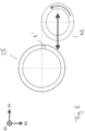
- FIG. 10 A pick-up solution is also schematically illustrated. It shows a skiving wheel S10 cutting a workpiece WS with internal gearing. The workpiece is clamped on a pick-up spindle P1. A regrinding tool N10 is clamped on another pick-up spindle P2, which is used to regrind the cutting wheel W10. This is done by positioning it along the Y axis.
Landscapes
- Engineering & Computer Science (AREA)
- Mechanical Engineering (AREA)
- Human Computer Interaction (AREA)
- Manufacturing & Machinery (AREA)
- Physics & Mathematics (AREA)
- General Physics & Mathematics (AREA)
- Automation & Control Theory (AREA)
- Finish Polishing, Edge Sharpening, And Grinding By Specific Grinding Devices (AREA)
- Gear Processing (AREA)
Applications Claiming Priority (2)
| Application Number | Priority Date | Filing Date | Title |
|---|---|---|---|
| DE102017011978.3A DE102017011978A1 (de) | 2017-12-22 | 2017-12-22 | Verfahren zur Bearbeituung von Verzahnungen und Verzahnungsmaschine |
| PCT/EP2018/081969 WO2019120831A1 (de) | 2017-12-22 | 2018-11-20 | Verfahren zur bearbeitung von verzahnungen, sowie verzahnungsmaschine und steuerprogramm dafür |
Publications (2)
| Publication Number | Publication Date |
|---|---|
| EP3727734A1 EP3727734A1 (de) | 2020-10-28 |
| EP3727734B1 true EP3727734B1 (de) | 2025-04-02 |
Family
ID=64456963
Family Applications (1)
| Application Number | Title | Priority Date | Filing Date |
|---|---|---|---|
| EP18807932.1A Active EP3727734B1 (de) | 2017-12-22 | 2018-11-20 | Verfahren zur bearbeitung von verzahnungen, sowie verzahnungsmaschine und steuerprogramm dafür |
Country Status (8)
| Country | Link |
|---|---|
| US (1) | US20210178499A1 (https=) |
| EP (1) | EP3727734B1 (https=) |
| JP (1) | JP7394762B2 (https=) |
| KR (1) | KR102622113B1 (https=) |
| CN (1) | CN111479646A (https=) |
| DE (1) | DE102017011978A1 (https=) |
| ES (1) | ES3022809T3 (https=) |
| WO (1) | WO2019120831A1 (https=) |
Families Citing this family (9)
| Publication number | Priority date | Publication date | Assignee | Title |
|---|---|---|---|---|
| CH715794B8 (de) * | 2019-07-17 | 2020-11-13 | Reishauer Ag | Werkzeugmaschine für die Wälzbearbeitung von Rotationsteilen mit nutförmigen Profilen. |
| DE102019006809A1 (de) * | 2019-09-30 | 2021-04-01 | Gleason-Pfauter Maschinenfabrik Gmbh | Verfahren der schneidenden Erzeugung oder Bearbeitung einer jeweils gleichen Verzahnung an mehreren Werkstücken |
| CN112157484B (zh) * | 2020-09-09 | 2022-05-20 | 华中科技大学 | 一种树脂基复合材料的磨削方法 |
| US20230398619A1 (en) * | 2020-10-14 | 2023-12-14 | Eaton Intelligent Power Limited | Near zero degrees cross-axis angle gear cutter and method of gear cutting using such a tool |
| CN112846416B (zh) * | 2020-12-31 | 2021-12-21 | 泰州市特星模具有限公司 | 一种数字化智能控制齿轮加工机床 |
| CN114951838B (zh) * | 2022-06-21 | 2024-05-03 | 湖南中大创远数控装备有限公司 | 一种蜗杆砂轮磨齿机 |
| CN115007951B (zh) * | 2022-07-14 | 2023-11-10 | 无锡市神力齿轮冷挤有限公司 | 一种全自动铣齿设备 |
| DE102023000941A1 (de) | 2023-03-13 | 2024-09-19 | Gleason-Pfauter Maschinenfabrik Gmbh | Verzahnungsbearbeitung durch wälzschälen, hartschälen oder wälzstossen, und entsprechendes verzahnungswerkzeug |
| DE102023003610A1 (de) | 2023-09-04 | 2025-03-06 | Gleason Switzerland Ag | Werkzeugkopf und Verzahnungsmaschine für das Hartschälen oder Wälzschälen |
Family Cites Families (23)
| Publication number | Priority date | Publication date | Assignee | Title |
|---|---|---|---|---|
| EP0133320B1 (de) * | 1982-01-12 | 1987-07-15 | Werkzeugmaschinenfabrik Oerlikon-Bührle AG | Messerkopf für eine Verzahnungsmaschine |
| JPS60259363A (ja) * | 1984-06-05 | 1985-12-21 | Mitsubishi Heavy Ind Ltd | ギヤシエイパの刃付装置 |
| JPH0516014A (ja) * | 1991-07-10 | 1993-01-26 | Rikagaku Kenkyusho | 多刃カツタによる鏡面切削装置 |
| DE4302353A1 (en) * | 1993-01-28 | 1993-08-19 | Kapp Werkzeugmasch | Grinding machine for shaping and profiling workpiece e.g. toothed wheel - uses computer to redress grinding wheel controlled by differences between stored profile and measured workpiece profile |
| JP3547469B2 (ja) * | 1994-02-25 | 2004-07-28 | 本田技研工業株式会社 | 歯車の仕上加工装置 |
| JP4339449B2 (ja) * | 1999-07-05 | 2009-10-07 | ダイジ▲ェ▼ット工業株式会社 | ホブ用超硬材料 |
| EP1195668B1 (de) * | 2000-09-27 | 2004-03-10 | LIEBHERR-VERZAHNTECHNIK GmbH | Prozessüberwachung zur Verschleisserkennung an Verzahnungswerkzeugen |
| JP3698656B2 (ja) * | 2001-06-06 | 2005-09-21 | 株式会社不二越 | 切削工具 |
| JP3825764B2 (ja) * | 2003-06-23 | 2006-09-27 | 三菱マテリアル神戸ツールズ株式会社 | 再研摩・再コーティングホブ、ホブの再研摩・再コーティング方法 |
| DE10330474B4 (de) * | 2003-07-05 | 2009-03-05 | Fette Gmbh | Vorrichtung zur Herstellung eines Zahnrads aus einem Zahnradrohling |
| CA2581724C (en) * | 2005-02-03 | 2010-11-30 | David J. Fisher | Method and apparatus for manufacturing a face gear |
| DE102008010301A1 (de) * | 2008-02-21 | 2009-09-03 | Liebherr-Verzahntechnik Gmbh | Verfahren zum Betrieb einer Verzahnungsschleifmaschine |
| EP2161092B1 (de) * | 2008-09-04 | 2012-04-18 | GLEASON-PFAUTER, Maschinenfabrik GmbH | Verzahnungsschleifmaschine und Verfahren zum Abrichten eines Schleifwerkzeuges |
| JP5285672B2 (ja) * | 2010-09-07 | 2013-09-11 | 三菱重工業株式会社 | 歯車研削盤 |
| DE102011009027A1 (de) * | 2011-01-20 | 2012-07-26 | Gleason-Pfauter Maschinenfabrik Gmbh | Verfahren zum spanenden Bearbeiten eines Werkstückes und dazu ausgelegte Werkzeugmaschine |
| DE102011006993B4 (de) * | 2011-04-07 | 2025-10-09 | MODUL MT Verzahntechnik GmbH | Verfahren zur Herstellung von Verzahnungen an Werkstücken |
| DE102011103216A1 (de) * | 2011-06-01 | 2012-12-06 | Liebherr-Verzahntechnik Gmbh | Verfahren zum Abrichten eines Werkzeugs |
| EP2537615B1 (de) | 2011-06-21 | 2014-11-26 | Klingelnberg AG | Robustes Verfahren zum Wälzschälen |
| EP2732895B1 (de) * | 2012-11-14 | 2015-10-21 | Burri Werkzeugmaschinen GmbH & Co. KG | Werkzeugmaschine zur Herstellung von Profilen |
| DE202013012505U1 (de) * | 2013-07-31 | 2017-01-30 | Gleason-Pfauter Maschinenfabrik Gmbh | Steuerprogramm für ein Bearbeiten von Zahnkanten und damit ausgestattete Bearbeitungsstation |
| DE102015008963A1 (de) * | 2015-07-10 | 2017-01-12 | Liebherr-Verzahntechnik Gmbh | Verfahren zum Abrichten eines Werkzeuges |
| JP6720543B2 (ja) * | 2016-01-14 | 2020-07-08 | アイシン精機株式会社 | 歯車加工方法 |
| DE102016004112A1 (de) * | 2016-04-05 | 2017-10-05 | Gleason-Pfauter Maschinenfabrik Gmbh | Verfahren zur erzeugung einer abtragung an einer zahnstirnkante und dazu ausgelegte vorrichtung |
-
2017
- 2017-12-22 DE DE102017011978.3A patent/DE102017011978A1/de active Pending
-
2018
- 2018-11-20 JP JP2020532911A patent/JP7394762B2/ja active Active
- 2018-11-20 EP EP18807932.1A patent/EP3727734B1/de active Active
- 2018-11-20 KR KR1020207017105A patent/KR102622113B1/ko active Active
- 2018-11-20 WO PCT/EP2018/081969 patent/WO2019120831A1/de not_active Ceased
- 2018-11-20 ES ES18807932T patent/ES3022809T3/es active Active
- 2018-11-20 CN CN201880080843.3A patent/CN111479646A/zh active Pending
- 2018-11-20 US US16/770,435 patent/US20210178499A1/en not_active Abandoned
Also Published As
| Publication number | Publication date |
|---|---|
| DE102017011978A1 (de) | 2019-06-27 |
| JP7394762B2 (ja) | 2023-12-08 |
| CN111479646A (zh) | 2020-07-31 |
| ES3022809T3 (en) | 2025-05-29 |
| US20210178499A1 (en) | 2021-06-17 |
| KR20200097274A (ko) | 2020-08-18 |
| EP3727734A1 (de) | 2020-10-28 |
| KR102622113B1 (ko) | 2024-01-08 |
| JP2021506602A (ja) | 2021-02-22 |
| WO2019120831A1 (de) | 2019-06-27 |
Similar Documents
| Publication | Publication Date | Title |
|---|---|---|
| EP3727734B1 (de) | Verfahren zur bearbeitung von verzahnungen, sowie verzahnungsmaschine und steuerprogramm dafür | |
| DE102006061759B4 (de) | Verzahnungsschleifmaschine und Verfahren zum Schleifen eines Werkstücks | |
| EP2823924B1 (de) | Doppelabrichter | |
| DE102014008475B4 (de) | Verfahren zum Bearbeiten eines Werkstücks, Werkzeuganordnung und Verzahnungsmaschine | |
| EP2367656B1 (de) | Werkzeug maschine und verfahren zur herstellung von verzahnungen | |
| DE3320042C2 (https=) | ||
| DE19529786C1 (de) | Verfahren und Werkzeug zur Erzeugung einer konkaven Oberfläche an einem Brillenglasrohling | |
| EP3552743B1 (de) | Vorrichtung und verfahren zur anfasbearbeitung eines verzahnten werkstücks | |
| EP4037859B1 (de) | Verfahren der schneidenden erzeugung oder bearbeitung einer jeweils gleichen verzahnung an mehreren werkstücken sowie maschinengruppe und steuerprogramm dafür | |
| EP2255910A1 (de) | Verzahnmaschine | |
| EP3230001A1 (de) | Verfahren zum bearbeiten einer verzahnung, werkzeuganordnung und verzahnungsmaschine | |
| DE102018001477A1 (de) | Anfaswerkzeug und Verfahren zum Anfasen von Verzahnungen | |
| WO2013083231A2 (de) | Verfahren zum schleifen von verzahnten werkstücken und dazu ausgelegte vorrichtung | |
| EP1144138B1 (de) | Verfahren zum schleifen von wenigstens einer fläche an einem in der zerspantechnik eingesetzten schneidmesser, verwendung des verfahrens und schleifscheibe zur durchführung des verfahrens | |
| EP3651924B1 (de) | Verfahren zum bearbeiten einer verzahnung und dazu hergerichtete verzahnungsmaschine, sowie computerprogrammprodukt dafür | |
| EP2851150A2 (de) | Werkzeug, Verfahren und Maschine zum Erzeugen eines Verzahnungsprofils an einem Werkstück durch Wälzschälen | |
| DE102006014972B4 (de) | Kombiniertes Bearbeitungsverfahren und Bearbeitungseinrichtung | |
| EP0885082B1 (de) | Verfahren und vorrichtung zum bearbeiten der lagersitze von kurbelwellen | |
| WO2017097416A1 (de) | Verfahren zum erzeugen oder bearbeiten von verzahnungen und dazu ausgelegte verzahnungsmaschine | |
| DE202019001722U1 (de) | Anfasanordnung | |
| DE102015013497A1 (de) | Verfahren zum bearbeiten einer verzahnung und anordnung dafür | |
| WO2024099987A1 (de) | Verfahren zur verzahnungsbearbeitung mit darauffolgendem anfasen | |
| DE4406272C2 (de) | Werkzeugmaschine zum Drehräumen, Dreh-Drehräumen oder Drehen und Verfahren zur spanenden Bearbeitung von rotationssymmetrischen Werkstücken | |
| DE10103121A1 (de) | Verfahren zum Schleifen von wenigstens einer Fläche an einem in der Zerspantechnik eingesetzten Schneidmesser | |
| EP3330026B1 (de) | Drehräumwerkzeug |
Legal Events
| Date | Code | Title | Description |
|---|---|---|---|
| STAA | Information on the status of an ep patent application or granted ep patent |
Free format text: STATUS: UNKNOWN |
|
| STAA | Information on the status of an ep patent application or granted ep patent |
Free format text: STATUS: THE INTERNATIONAL PUBLICATION HAS BEEN MADE |
|
| PUAI | Public reference made under article 153(3) epc to a published international application that has entered the european phase |
Free format text: ORIGINAL CODE: 0009012 |
|
| STAA | Information on the status of an ep patent application or granted ep patent |
Free format text: STATUS: REQUEST FOR EXAMINATION WAS MADE |
|
| 17P | Request for examination filed |
Effective date: 20200609 |
|
| AK | Designated contracting states |
Kind code of ref document: A1 Designated state(s): AL AT BE BG CH CY CZ DE DK EE ES FI FR GB GR HR HU IE IS IT LI LT LU LV MC MK MT NL NO PL PT RO RS SE SI SK SM TR |
|
| AX | Request for extension of the european patent |
Extension state: BA ME |
|
| DAV | Request for validation of the european patent (deleted) | ||
| DAX | Request for extension of the european patent (deleted) | ||
| STAA | Information on the status of an ep patent application or granted ep patent |
Free format text: STATUS: EXAMINATION IS IN PROGRESS |
|
| 17Q | First examination report despatched |
Effective date: 20220825 |
|
| RIC1 | Information provided on ipc code assigned before grant |
Ipc: G05B 19/408 20060101ALI20241120BHEP Ipc: G05B 19/18 20060101ALI20241120BHEP Ipc: B23F 5/16 20060101ALI20241120BHEP Ipc: B23F 23/12 20060101AFI20241120BHEP |
|
| GRAP | Despatch of communication of intention to grant a patent |
Free format text: ORIGINAL CODE: EPIDOSNIGR1 |
|
| STAA | Information on the status of an ep patent application or granted ep patent |
Free format text: STATUS: GRANT OF PATENT IS INTENDED |
|
| INTG | Intention to grant announced |
Effective date: 20250110 |
|
| GRAS | Grant fee paid |
Free format text: ORIGINAL CODE: EPIDOSNIGR3 |
|
| GRAA | (expected) grant |
Free format text: ORIGINAL CODE: 0009210 |
|
| STAA | Information on the status of an ep patent application or granted ep patent |
Free format text: STATUS: THE PATENT HAS BEEN GRANTED |
|
| AK | Designated contracting states |
Kind code of ref document: B1 Designated state(s): AL AT BE BG CH CY CZ DE DK EE ES FI FR GB GR HR HU IE IS IT LI LT LU LV MC MK MT NL NO PL PT RO RS SE SI SK SM TR |
|
| REG | Reference to a national code |
Ref country code: GB Ref legal event code: FG4D Free format text: NOT ENGLISH |
|
| REG | Reference to a national code |
Ref country code: CH Ref legal event code: EP |
|
| REG | Reference to a national code |
Ref country code: IE Ref legal event code: FG4D Free format text: LANGUAGE OF EP DOCUMENT: GERMAN |
|
| REG | Reference to a national code |
Ref country code: DE Ref legal event code: R096 Ref document number: 502018015717 Country of ref document: DE |
|
| REG | Reference to a national code |
Ref country code: ES Ref legal event code: FG2A Ref document number: 3022809 Country of ref document: ES Kind code of ref document: T3 Effective date: 20250529 |
|
| REG | Reference to a national code |
Ref country code: NL Ref legal event code: MP Effective date: 20250402 |
|
| PG25 | Lapsed in a contracting state [announced via postgrant information from national office to epo] |
Ref country code: NL Free format text: LAPSE BECAUSE OF FAILURE TO SUBMIT A TRANSLATION OF THE DESCRIPTION OR TO PAY THE FEE WITHIN THE PRESCRIBED TIME-LIMIT Effective date: 20250402 |
|
| PG25 | Lapsed in a contracting state [announced via postgrant information from national office to epo] |
Ref country code: FI Free format text: LAPSE BECAUSE OF FAILURE TO SUBMIT A TRANSLATION OF THE DESCRIPTION OR TO PAY THE FEE WITHIN THE PRESCRIBED TIME-LIMIT Effective date: 20250402 Ref country code: PT Free format text: LAPSE BECAUSE OF FAILURE TO SUBMIT A TRANSLATION OF THE DESCRIPTION OR TO PAY THE FEE WITHIN THE PRESCRIBED TIME-LIMIT Effective date: 20250804 |
|
| REG | Reference to a national code |
Ref country code: LT Ref legal event code: MG9D |
|
| PG25 | Lapsed in a contracting state [announced via postgrant information from national office to epo] |
Ref country code: GR Free format text: LAPSE BECAUSE OF FAILURE TO SUBMIT A TRANSLATION OF THE DESCRIPTION OR TO PAY THE FEE WITHIN THE PRESCRIBED TIME-LIMIT Effective date: 20250703 Ref country code: NO Free format text: LAPSE BECAUSE OF FAILURE TO SUBMIT A TRANSLATION OF THE DESCRIPTION OR TO PAY THE FEE WITHIN THE PRESCRIBED TIME-LIMIT Effective date: 20250702 |
|
| PG25 | Lapsed in a contracting state [announced via postgrant information from national office to epo] |
Ref country code: PL Free format text: LAPSE BECAUSE OF FAILURE TO SUBMIT A TRANSLATION OF THE DESCRIPTION OR TO PAY THE FEE WITHIN THE PRESCRIBED TIME-LIMIT Effective date: 20250402 |
|
| PG25 | Lapsed in a contracting state [announced via postgrant information from national office to epo] |
Ref country code: BG Free format text: LAPSE BECAUSE OF FAILURE TO SUBMIT A TRANSLATION OF THE DESCRIPTION OR TO PAY THE FEE WITHIN THE PRESCRIBED TIME-LIMIT Effective date: 20250402 |
|
| PG25 | Lapsed in a contracting state [announced via postgrant information from national office to epo] |
Ref country code: HR Free format text: LAPSE BECAUSE OF FAILURE TO SUBMIT A TRANSLATION OF THE DESCRIPTION OR TO PAY THE FEE WITHIN THE PRESCRIBED TIME-LIMIT Effective date: 20250402 |
|
| PG25 | Lapsed in a contracting state [announced via postgrant information from national office to epo] |
Ref country code: RS Free format text: LAPSE BECAUSE OF FAILURE TO SUBMIT A TRANSLATION OF THE DESCRIPTION OR TO PAY THE FEE WITHIN THE PRESCRIBED TIME-LIMIT Effective date: 20250702 |
|
| PG25 | Lapsed in a contracting state [announced via postgrant information from national office to epo] |
Ref country code: IS Free format text: LAPSE BECAUSE OF FAILURE TO SUBMIT A TRANSLATION OF THE DESCRIPTION OR TO PAY THE FEE WITHIN THE PRESCRIBED TIME-LIMIT Effective date: 20250802 |
|
| PG25 | Lapsed in a contracting state [announced via postgrant information from national office to epo] |
Ref country code: LV Free format text: LAPSE BECAUSE OF FAILURE TO SUBMIT A TRANSLATION OF THE DESCRIPTION OR TO PAY THE FEE WITHIN THE PRESCRIBED TIME-LIMIT Effective date: 20250402 |
|
| REG | Reference to a national code |
Ref country code: CH Ref legal event code: U11 Free format text: ST27 STATUS EVENT CODE: U-0-0-U10-U11 (AS PROVIDED BY THE NATIONAL OFFICE) Effective date: 20251201 |
|
| REG | Reference to a national code |
Ref country code: DE Ref legal event code: R097 Ref document number: 502018015717 Country of ref document: DE |
|
| PGFP | Annual fee paid to national office [announced via postgrant information from national office to epo] |
Ref country code: DE Payment date: 20251128 Year of fee payment: 8 |
|
| PG25 | Lapsed in a contracting state [announced via postgrant information from national office to epo] |
Ref country code: DK Free format text: LAPSE BECAUSE OF FAILURE TO SUBMIT A TRANSLATION OF THE DESCRIPTION OR TO PAY THE FEE WITHIN THE PRESCRIBED TIME-LIMIT Effective date: 20250402 Ref country code: SM Free format text: LAPSE BECAUSE OF FAILURE TO SUBMIT A TRANSLATION OF THE DESCRIPTION OR TO PAY THE FEE WITHIN THE PRESCRIBED TIME-LIMIT Effective date: 20250402 |
|
| P01 | Opt-out of the competence of the unified patent court (upc) registered |
Free format text: CASE NUMBER: UPC_APP_0016040_3727734/2025 Effective date: 20251205 |
|
| PGFP | Annual fee paid to national office [announced via postgrant information from national office to epo] |
Ref country code: IT Payment date: 20251119 Year of fee payment: 8 |
|
| PGFP | Annual fee paid to national office [announced via postgrant information from national office to epo] |
Ref country code: CH Payment date: 20251201 Year of fee payment: 8 |
|
| PGFP | Annual fee paid to national office [announced via postgrant information from national office to epo] |
Ref country code: CZ Payment date: 20251106 Year of fee payment: 8 |
|
| PG25 | Lapsed in a contracting state [announced via postgrant information from national office to epo] |
Ref country code: EE Free format text: LAPSE BECAUSE OF FAILURE TO SUBMIT A TRANSLATION OF THE DESCRIPTION OR TO PAY THE FEE WITHIN THE PRESCRIBED TIME-LIMIT Effective date: 20250402 |
|
| PG25 | Lapsed in a contracting state [announced via postgrant information from national office to epo] |
Ref country code: RO Free format text: LAPSE BECAUSE OF FAILURE TO SUBMIT A TRANSLATION OF THE DESCRIPTION OR TO PAY THE FEE WITHIN THE PRESCRIBED TIME-LIMIT Effective date: 20250402 Ref country code: SK Free format text: LAPSE BECAUSE OF FAILURE TO SUBMIT A TRANSLATION OF THE DESCRIPTION OR TO PAY THE FEE WITHIN THE PRESCRIBED TIME-LIMIT Effective date: 20250402 |
|
| PGFP | Annual fee paid to national office [announced via postgrant information from national office to epo] |
Ref country code: ES Payment date: 20251201 Year of fee payment: 8 |
|
| PLBE | No opposition filed within time limit |
Free format text: ORIGINAL CODE: 0009261 |
|
| STAA | Information on the status of an ep patent application or granted ep patent |
Free format text: STATUS: NO OPPOSITION FILED WITHIN TIME LIMIT |
|
| REG | Reference to a national code |
Ref country code: CH Ref legal event code: L10 Free format text: ST27 STATUS EVENT CODE: U-0-0-L10-L00 (AS PROVIDED BY THE NATIONAL OFFICE) Effective date: 20260211 |
|
| 26N | No opposition filed |
Effective date: 20260105 |