EP3722121A1 - Bras integral à ressort - Google Patents
Bras integral à ressort Download PDFInfo
- Publication number
- EP3722121A1 EP3722121A1 EP19168696.3A EP19168696A EP3722121A1 EP 3722121 A1 EP3722121 A1 EP 3722121A1 EP 19168696 A EP19168696 A EP 19168696A EP 3722121 A1 EP3722121 A1 EP 3722121A1
- Authority
- EP
- European Patent Office
- Prior art keywords
- spring link
- constriction
- spring
- distance
- flanks
- Prior art date
- Legal status (The legal status is an assumption and is not a legal conclusion. Google has not performed a legal analysis and makes no representation as to the accuracy of the status listed.)
- Granted
Links
- 239000006096 absorbing agent Substances 0.000 claims abstract description 21
- 230000035939 shock Effects 0.000 claims abstract description 19
- 239000002184 metal Substances 0.000 claims abstract description 8
- 239000000725 suspension Substances 0.000 claims abstract description 5
- 239000011324 bead Substances 0.000 claims description 8
- 230000007423 decrease Effects 0.000 claims description 5
- 238000004519 manufacturing process Methods 0.000 abstract description 12
- 229910000831 Steel Inorganic materials 0.000 description 5
- 239000010959 steel Substances 0.000 description 5
- 239000000463 material Substances 0.000 description 4
- 230000003014 reinforcing effect Effects 0.000 description 3
- 238000009434 installation Methods 0.000 description 2
- 238000002485 combustion reaction Methods 0.000 description 1
- 230000002349 favourable effect Effects 0.000 description 1
- 238000004080 punching Methods 0.000 description 1
Images


Classifications
-
- B—PERFORMING OPERATIONS; TRANSPORTING
- B60—VEHICLES IN GENERAL
- B60G—VEHICLE SUSPENSION ARRANGEMENTS
- B60G13/00—Resilient suspensions characterised by arrangement, location or type of vibration dampers
- B60G13/001—Arrangements for attachment of dampers
- B60G13/005—Arrangements for attachment of dampers characterised by the mounting on the axle or suspension arm of the damper unit
-
- B—PERFORMING OPERATIONS; TRANSPORTING
- B60—VEHICLES IN GENERAL
- B60G—VEHICLE SUSPENSION ARRANGEMENTS
- B60G11/00—Resilient suspensions characterised by arrangement, location or kind of springs
- B60G11/14—Resilient suspensions characterised by arrangement, location or kind of springs having helical, spiral or coil springs only
- B60G11/16—Resilient suspensions characterised by arrangement, location or kind of springs having helical, spiral or coil springs only characterised by means specially adapted for attaching the spring to axle or sprung part of the vehicle
-
- B—PERFORMING OPERATIONS; TRANSPORTING
- B60—VEHICLES IN GENERAL
- B60G—VEHICLE SUSPENSION ARRANGEMENTS
- B60G7/00—Pivoted suspension arms; Accessories thereof
- B60G7/001—Suspension arms, e.g. constructional features
-
- B—PERFORMING OPERATIONS; TRANSPORTING
- B60—VEHICLES IN GENERAL
- B60G—VEHICLE SUSPENSION ARRANGEMENTS
- B60G7/00—Pivoted suspension arms; Accessories thereof
- B60G7/008—Attaching arms to unsprung part of vehicle
-
- B—PERFORMING OPERATIONS; TRANSPORTING
- B60—VEHICLES IN GENERAL
- B60G—VEHICLE SUSPENSION ARRANGEMENTS
- B60G7/00—Pivoted suspension arms; Accessories thereof
- B60G7/02—Attaching arms to sprung part of vehicle
-
- B—PERFORMING OPERATIONS; TRANSPORTING
- B60—VEHICLES IN GENERAL
- B60G—VEHICLE SUSPENSION ARRANGEMENTS
- B60G2202/00—Indexing codes relating to the type of spring, damper or actuator
- B60G2202/10—Type of spring
- B60G2202/12—Wound spring
-
- B—PERFORMING OPERATIONS; TRANSPORTING
- B60—VEHICLES IN GENERAL
- B60G—VEHICLE SUSPENSION ARRANGEMENTS
- B60G2204/00—Indexing codes related to suspensions per se or to auxiliary parts
- B60G2204/10—Mounting of suspension elements
- B60G2204/12—Mounting of springs or dampers
- B60G2204/124—Mounting of coil springs
- B60G2204/1244—Mounting of coil springs on a suspension arm
-
- B—PERFORMING OPERATIONS; TRANSPORTING
- B60—VEHICLES IN GENERAL
- B60G—VEHICLE SUSPENSION ARRANGEMENTS
- B60G2204/00—Indexing codes related to suspensions per se or to auxiliary parts
- B60G2204/10—Mounting of suspension elements
- B60G2204/12—Mounting of springs or dampers
- B60G2204/129—Damper mount on wheel suspension or knuckle
-
- B—PERFORMING OPERATIONS; TRANSPORTING
- B60—VEHICLES IN GENERAL
- B60G—VEHICLE SUSPENSION ARRANGEMENTS
- B60G2204/00—Indexing codes related to suspensions per se or to auxiliary parts
- B60G2204/10—Mounting of suspension elements
- B60G2204/14—Mounting of suspension arms
- B60G2204/143—Mounting of suspension arms on the vehicle body or chassis
-
- B—PERFORMING OPERATIONS; TRANSPORTING
- B60—VEHICLES IN GENERAL
- B60G—VEHICLE SUSPENSION ARRANGEMENTS
- B60G2204/00—Indexing codes related to suspensions per se or to auxiliary parts
- B60G2204/10—Mounting of suspension elements
- B60G2204/14—Mounting of suspension arms
- B60G2204/148—Mounting of suspension arms on the unsprung part of the vehicle, e.g. wheel knuckle or rigid axle
-
- B—PERFORMING OPERATIONS; TRANSPORTING
- B60—VEHICLES IN GENERAL
- B60G—VEHICLE SUSPENSION ARRANGEMENTS
- B60G2206/00—Indexing codes related to the manufacturing of suspensions: constructional features, the materials used, procedures or tools
- B60G2206/01—Constructional features of suspension elements, e.g. arms, dampers, springs
- B60G2206/10—Constructional features of arms
- B60G2206/14—Constructional features of arms the arm forming a U-shaped recess for fitting a bush
- B60G2206/141—The recess being integrally or seamlessly formed
-
- B—PERFORMING OPERATIONS; TRANSPORTING
- B60—VEHICLES IN GENERAL
- B60G—VEHICLE SUSPENSION ARRANGEMENTS
- B60G2206/00—Indexing codes related to the manufacturing of suspensions: constructional features, the materials used, procedures or tools
- B60G2206/01—Constructional features of suspension elements, e.g. arms, dampers, springs
- B60G2206/10—Constructional features of arms
- B60G2206/16—Constructional features of arms the arm having a U profile and/or made of a plate
-
- B—PERFORMING OPERATIONS; TRANSPORTING
- B60—VEHICLES IN GENERAL
- B60G—VEHICLE SUSPENSION ARRANGEMENTS
- B60G2206/00—Indexing codes related to the manufacturing of suspensions: constructional features, the materials used, procedures or tools
- B60G2206/01—Constructional features of suspension elements, e.g. arms, dampers, springs
- B60G2206/70—Materials used in suspensions
- B60G2206/72—Steel
- B60G2206/722—Plates
Definitions
- the invention relates to a single-shell spring link formed from sheet metal for a wheel suspension of a motor vehicle, with upwardly directed side legs connected to one another by a floor, with a first end section for connection to a chassis beam, with a second end section for connection on the wheel side, with a spring receiving section which is located between the two end sections and has a spring support surface formed on the floor, and with a damper receiving section formed between the spring receiving section and the second end section for connecting a shock absorber.
- Spring links are used to guide a chassis wheel on a wheel suspension of a motor vehicle. They have a section for supporting a spring and a section for connecting a shock absorber or, alternatively, a section for supporting a spring-shock absorber arrangement, the spring or spring-shock absorber arrangement in turn being supported against the body.
- a spring link of the type mentioned above is from the DE 10 2011 000 462 A1 known.
- the spring link which was developed in the applicant's group of companies for motor vehicles with internal combustion engines and a certain maximum axle load, has proven itself in practice.
- the spring link when used in similar motor vehicles with electric drive in which a significantly higher axle load occurs due to the high weight of the drive accumulator, is not sufficiently rigid at the damper connection between the wheel-side connection and the spring support surface and sometimes fails.
- the main reason for the component failure is an excessive expansion or deformation of the side legs in the x-direction (i.e. in the horizontal vehicle longitudinal direction) due to an excessive axle load in the z-direction (ie along the vertical vertical axis of the vehicle).
- a known measure for improving the rigidity, in particular the flexural rigidity of a spring link that is exposed to high axle loads, consists in the use of sheet steel of higher material thickness in the manufacture of the spring link.
- an increase in the material thickness leads to a considerable increase in weight per spring link and higher material costs.
- the invention is based on the object of creating a spring link of the type mentioned at the outset, which has an improved rigidity with regard to high axle loads with a relatively low component weight and low manufacturing costs.
- the single-shell spring link according to the invention is characterized in that a U-shaped constriction is formed between the spring support surface and the damper receiving section which runs in the bottom and in the side legs of the spring link.
- the U-shaped constriction can also be referred to as a U-shaped bead.
- the U-shaped constriction makes it possible to achieve a spring link of the generic type with significantly improved rigidity with regard to high axle loads. Since neither the material thickness of the metal sheet used for the manufacture of the spring link has to be increased nor bridge plates or other reinforcing additional sheets have to be attached to the spring link, the spring link can be provided with a relatively low component weight and low manufacturing costs.
- the constriction is defined by a main plane, a second plane and a third plane, the main plane running tangentially to the underside of the floor opposite the spring support surface, the second plane being above and parallel to the main plane and through the The high point of the constriction runs in the underside of the floor, the third plane running parallel to the main plane and through an intersection, the intersection being an intersection of a straight line with a lower outer contour line of one of the side legs, the straight line being perpendicular to the main plane and through a The center of a mounting hole which is formed in the damper receiving section and is used to connect the shock absorber runs, and wherein the second plane is spaced apart relative to the main plane and the third plane is spaced apart relative to the second plane.
- the third level can also be referred to as the damper level or damper reference level.
- the third level (damper level) can run in, below or above the main level.
- the distance between the third plane and the second plane is preferably greater than the distance between the second plane and the main plane.
- Another embodiment of the spring link according to the invention is characterized in that the distance between the upper edge and the floor at the constriction has a minimum.
- This configuration has proven to be very advantageous in order to achieve a spring link according to the invention which has improved rigidity with regard to high axle loads with a relatively low component weight and low manufacturing costs.
- Another advantageous embodiment of the spring link is characterized in that the distance between the flanks at the constriction is smaller than the distance between the flanks at the damper receiving section.
- This configuration also contributes to improved rigidity with regard to high axle loads, especially when the distance between the flanks at the constriction is at least 3 mm, preferably at least 5 mm less than the distance between the flanks at the damper receiving section.
- the distance between its flanks at the constriction is greater than the distance between the flanks at the second end section of the spring link.
- the distance between the flanks at the constriction is at least 5 mm, preferably at least 8 mm greater than the distance between the flanks at the second end section.
- the distance between its flanks at the constriction can also be smaller than or equal to the distance between the flanks at the second end section of the spring link.
- the distance between the flanks at the constriction can be at least 3 mm, preferably at least 5 mm smaller than the distance between the flanks at the second end section.
- a further embodiment of the invention provides that a depth (profile depth) of the constriction is relative to the above-mentioned main plane in the range from 1.5 mm to 40 mm, preferably in the range from 5 mm to 40 mm, particularly preferably in the range from 10 mm to 40 mm.
- Another embodiment of the invention provides that a depth (profile depth) of the constriction relative to the above-mentioned third level (damper level) in the range from 1.5 mm to 45 mm, preferably in the range from 5 mm to 45 mm, particularly preferably in Range from 10 mm to 45 mm.
- the distance between the flanks initially increases starting from the constriction to the damper receiving section and then decreases in the direction of fastening holes formed in the side legs, which are used to connect the shock absorber. This further improves the rigidity of the relatively lightweight spring link at low manufacturing costs.
- the respective side limb has an outwardly protruding flange on its upper edge, which is of different widths along the side limb and its greatest width at the constriction having. This further optimizes the stiffness of the spring link against expansion or deformation of the side legs when the axle load is high.
- the flange of the respective side limb preferably extends continuously from the first end section to the second end section of the spring link. An even greater rigidity of the spring link can be achieved if, according to a further embodiment of the spring link, the flange has an outer edge which is beveled downward relative to its upper side and which extends at least along the spring receiving section and the damper receiving section.
- the side legs define a fork-shaped bearing section for connecting a wheel carrier and for connecting the shock absorber.
- the fork-shaped bearing section delimits a niche-shaped cutout which extends from the second end section to a point which lies between the fastening holes, which are used to connect the shock absorber, and the constriction.
- the connection of the shock absorber to the side legs of the spring link increases the rigidity of the shock absorber against expansion of the side legs.
- the niche-shaped cutout in the fork-shaped bearing section reduces the component weight of the spring link.
- flange-shaped, mutually facing webs are formed on the fork-shaped bearing section, which delimit the niche-shaped cutout.
- the spring link its spring support surface has an opening on which an inwardly protruding collar is formed.
- the collar protrudes into the spring (helical spring) supported on the spring support surface.
- the upper edge of the collar is formed radially inward, so that the upper, circumferential edge of the collar is radially inwardly opposite a lower annular portion of the Collar protrudes.
- the collar can serve as a centering projection for the spring supported on the spring link.
- the collar improves the stiffness of the spring link.
- Another embodiment of the spring link provides that beads facing each other are formed in the side legs between the damper receiving section and the second end section.
- the beads are designed in such a way that the distance between the flanks of the side legs, starting from the damper receiving section, initially increases in the direction of the second end section and then decreases towards fastening holes that are used to connect a wheel carrier. These beads further improve the rigidity of the spring link with a relatively low component weight and low manufacturing costs.
- a further advantageous embodiment of the spring link is characterized in that the side legs on the first end section of the spring link define a fork-shaped bearing section for connecting the spring link to a chassis beam, the fork-shaped bearing section having aligned openings with collars for receiving a bearing bush.
- the collars which can also be referred to as passages, are preferably directed inwards, i. H. facing each other.
- an elongated opening is formed in the bottom of the spring link between the spring support surface and the first end section, which is used to connect the spring link to a chassis beam, which extends essentially parallel to the longitudinal center axis of the spring link.
- the length of this opening is preferably significantly greater than the distance between the flanks of the side legs on the constriction or on the damper receiving section and / or than the diameter of the opening formed in the spring support surface.
- the longitudinal edges of the elongated opening preferably run substantially or in sections divergent to one another, their spacing increases in the direction of the spring support surface. The elongated opening significantly reduces the component weight of the spring link.
- the spring link according to the invention is made of sheet steel with a yield point of at least 600 MPa, preferably at least 700 MPa, particularly preferably at least 750 MPa.
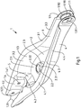
- a spring link 1 for a wheel suspension of a motor vehicle is shown.
- the spring link 1 has upwardly directed side legs 3, 4 connected to one another by a base 2 and is produced as a single-shell component from a metal plate by punching and reshaping. It has a first end section 1.1 for connection to a chassis beam and a second end section 1.2 for connection on the wheel side. Between the two end sections 1.1, 1.2 there is a spring receiving section 1.3, which has a spring support surface 2.1 formed on the bottom 2 for supporting a spring (helical spring) (not shown here). Furthermore, the spring link 1 between the spring receiving section 1.3 and the second end section 1.2 has a damper receiving section 1.4 for connecting a shock absorber (not shown).
- the spring link 1 is made of high-strength sheet metal, preferably high-strength sheet steel.
- the metal or steel sheet used for its production has a yield strength of at least 600 MPa, preferably at least 700 MPa, for example at least 800 MPa.
- the thickness of the metal or steel sheet used is, for example, in the range from 2.0 mm to 3.0 mm, preferably in the range from 2.0 mm to 2.6 mm.
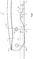
- a U-shaped constriction 5 is formed, which runs in the base 2 and in the side legs 3, 4.
- the constriction 5 can be defined using reference planes.
- the constriction 5 can be defined for example by a main plane (main reference plane) F1, a second plane E1 and a third plane D1, the main plane F1 running tangential to the underside of the base 2 opposite the spring support surface 2.1, the second plane E1 above and runs parallel to the main plane F1 and through the high point of the constriction 5 in the underside of the bottom 2, the third plane D1 parallel to the main plane F1 and through a Point of intersection S1 runs, the point of intersection S1 being the point of intersection of a straight line G with a lower outer contour line L of one of the side legs 4, and the straight line G perpendicular to the main plane F1 and through a center point M of one formed in the damper receiving section 1.4 serving to connect the shock absorber Mounting
- the constriction 5 is realized, for example, when the second plane E1 is spaced apart from the main plane F1 and the third plane D1 is spaced apart from the second plane E1.
- the constriction 5 is given when the distance A1 from the second plane E1 to the main plane F1 and the distance A2 from the third plane D1 to the second plane E1 are each greater than zero, the smaller distance A1 being the depth of the constriction 5 im Floor 2 corresponds.
- the depth of the constriction 5 in the base 2 of the spring link 1 can, for example, be in a range from 1.5 mm to 40 mm, in particular in a range from 8 mm to 16 mm.
- the distance A2 of the plane D1 to the plane E1 is preferably greater than the distance A1 of the second plane E1 to the main plane F1.
- the respective side leg 3, 4 of the spring link 1 defines an upper edge 3.1, 4.1.
- the distance between the upper edge 4.1 and the bottom 2 at the constriction 5 has a minimum.
- the side legs 3, 4 define mutually facing flanks 3.2, 4.2.
- the distance between the flanks 3.2, 4.2 from the upper edge 3.1, 4.1 in the direction of the base 2 gradually decreases.
- the mean distance A3 of the flanks 3.2, 4.2 from one another at the constriction 5 is smaller than the distance A4 between the flanks 3.2, 4.2 at the damper receiving section 1.4.
- the distance A3 of the flanks 3.2, 4.2 on the constriction 5 can be, for example, at least 3 mm, preferably at least 5 mm smaller than the distance A4 between the flanks 3.2, 4.2 on the damper receiving section 1.4.
- the spring link 1 is designed, for example, such that the distance A3 between the flanks 3.2, 4.2 at the constriction 5 is greater than the distance A5 between the flanks 3.2, 4.2 at the second end section 1.2.
- the distance A3 of the flanks 3.2, 4.2 at the constriction 5 can be at least 5 mm, preferably around be at least 8 mm greater than the distance A5 between the flanks 3.2, 4.2 at the second end section 1.2.
- the distance A3 of the flanks 3.2, 4.2 initially increases in the direction of the damper receiving section 1.4 and from a certain point in the direction of the fastening holes 1.41 formed in the side legs 3, 4, which are used to connect a shock absorber (not shown), from (cf. Fig. 1 and 3 ).
- the respective side leg 3, 4 of the spring link 1 has an outwardly projecting flange 3.3, 4.3 on its upper edge 3.1, 4.1.
- the flange 3.3, 4.3 extends essentially continuously from the first end section 1.1 to the second end section 1.2 of the spring link 1.
- the flange 3.3, 4.3 is of different widths along the respective side limbs 3, 4 and has its greatest width at the Constriction 5 (see Fig. 3 ).
- the flange 3.3, 4.3 has an outer edge 3.4, 4.4 which is beveled downward relative to its upper side. The downwardly curved outer edge 3.4, 4.4 extends essentially over the entire length of the flange 3.3, 4.3.
- the spring link 1 has a fork-shaped bearing section 1.21 defined by the side legs 3, 4, which additionally serves to connect a shock absorber.
- the fork-shaped bearing section 1.21 delimits a niche-shaped cutout 1.211 which extends from the second end section 1.2 to a point that lies between the fastening holes 1.41 and the constriction 5.
- flange-shaped, mutually facing webs 1.212 are formed which delimit the niche-shaped cutout 1.211.
- the spring support surface 2.1 has an opening 2.2 on which an inwardly protruding collar 2.3 is formed.
- the upper edge 2.31 of the collar 2.3 is preferably shaped radially inward, so that the upper, circumferential edge 2.32 of the Collar 2.3 protrudes radially inward relative to a lower annular portion of the collar 2.3.
- the side legs 3, 4 On the first end section 1.1 of the spring link 1, the side legs 3, 4 define a fork-shaped bearing section 1.11 for connecting the spring link to a chassis beam.
- the fork-shaped bearing section 1.11 has aligned openings 1.111 with a collar 1.112 for receiving a bearing bush.
- the collars 1.112 are preferably directed inward.
- the distance A6 between the side legs 3, 4 on the fork-shaped bearing section 1.11 is significantly smaller than the distance A5 between the side legs 3, 4 on the second end section 1.2 of the spring link 1.
- an elongated opening (passage opening) 2.5 is formed between the first end section 1.1 and the spring support surface 2.1, which extends essentially parallel to the longitudinal center axis of the spring link 1.
- the length of this opening 2.5 is significantly greater than the distance A4 between the flanks 3.2, 4.2 of the side legs 3, 4 on the damper receiving section 1.4.
- the longitudinal edges 2.51 of the opening 2.5 run essentially or in sections divergent to one another, their spacing increasing in the direction of the spring support surface 2.1.
- the design of the spring link 1 according to the invention is not limited to the exemplary embodiment shown in the drawing. Rather, numerous variants are conceivable which make use of the invention specified in the claims even in the case of designs that differ from the example shown.
- beads facing each other can be formed in the side legs 3, 4 between the damper receiving section 1.4 and the second end section 1.2.
- the beads are preferably designed such that the distance between the flanks 3.2, 4.2 of the side legs 3, 4 initially increases starting from the damper receiving section 1.4 in the direction of the second end section 1.2 and then decreases towards the fastening holes 1.23.
Priority Applications (3)
| Application Number | Priority Date | Filing Date | Title |
|---|---|---|---|
| EP19168696.3A EP3722121B1 (fr) | 2019-04-11 | 2019-04-11 | Bras de suspension monocoque à ressort |
| US16/840,608 US11254175B2 (en) | 2019-04-11 | 2020-04-06 | Single-shell spring control arm |
| CN202010265244.8A CN111806182B (zh) | 2019-04-11 | 2020-04-07 | 单壳式弹簧控制臂 |
Applications Claiming Priority (1)
| Application Number | Priority Date | Filing Date | Title |
|---|---|---|---|
| EP19168696.3A EP3722121B1 (fr) | 2019-04-11 | 2019-04-11 | Bras de suspension monocoque à ressort |
Publications (2)
| Publication Number | Publication Date |
|---|---|
| EP3722121A1 true EP3722121A1 (fr) | 2020-10-14 |
| EP3722121B1 EP3722121B1 (fr) | 2021-11-24 |
Family
ID=66105215
Family Applications (1)
| Application Number | Title | Priority Date | Filing Date |
|---|---|---|---|
| EP19168696.3A Active EP3722121B1 (fr) | 2019-04-11 | 2019-04-11 | Bras de suspension monocoque à ressort |
Country Status (3)
| Country | Link |
|---|---|
| US (1) | US11254175B2 (fr) |
| EP (1) | EP3722121B1 (fr) |
| CN (1) | CN111806182B (fr) |
Cited By (1)
| Publication number | Priority date | Publication date | Assignee | Title |
|---|---|---|---|---|
| EP4360919A1 (fr) * | 2022-10-31 | 2024-05-01 | Benteler Automobiltechnik GmbH | Bras de suspension à ressort |
Families Citing this family (13)
| Publication number | Priority date | Publication date | Assignee | Title |
|---|---|---|---|---|
| DE112019002832T5 (de) * | 2018-07-05 | 2021-03-04 | Shiloh Industries, Inc. | Fahrzeugaufhängungskomponente mit versteifungsmerkmal |
| CN112566800A (zh) * | 2018-08-20 | 2021-03-26 | 格鲁帕冲压有限责任公司 | 具有增强特征和连接节点的车辆悬架部件 |
| USD951151S1 (en) | 2019-10-31 | 2022-05-10 | Traxxas, L.P. | Model vehicle lower suspension arm |
| USD951150S1 (en) | 2019-10-31 | 2022-05-10 | Traxxas, L.P. | Model vehicle lower suspension arm |
| USD951148S1 (en) | 2019-10-31 | 2022-05-10 | Traxxas, L.P. | Model vehicle lower suspension arm |
| USD951149S1 (en) | 2019-10-31 | 2022-05-10 | Traxxas, L.P. | Model vehicle upper suspension arm |
| USD947957S1 (en) | 2019-12-11 | 2022-04-05 | Traxxas Lp | Model vehicle upper suspension arm |
| DE102020212778A1 (de) * | 2020-10-09 | 2022-04-14 | Zf Friedrichshafen Ag | Fahrwerkbauteil mit mindestens einem Verbindungsabschnitt zum Verbinden mit einem Befestigungsabschnitt eines Fahrwerkelements |
| JP2022154817A (ja) * | 2021-03-30 | 2022-10-13 | マツダ株式会社 | 自動車のサスペンション装置 |
| CN113525002A (zh) * | 2021-07-30 | 2021-10-22 | 岚图汽车科技有限公司 | 一种兼容性的弹簧臂 |
| USD1014656S1 (en) | 2021-11-16 | 2024-02-13 | Traxxas, L.P. | Model vehicle suspension arm |
| USD1014655S1 (en) | 2021-11-16 | 2024-02-13 | Traxxas, L.P. | Model vehicle suspension arm |
| USD1025846S1 (en) * | 2022-02-15 | 2024-05-07 | Arctic Cat, Inc. | Spindle for a recreational vehicle |
Citations (5)
| Publication number | Priority date | Publication date | Assignee | Title |
|---|---|---|---|---|
| GB2198398A (en) * | 1986-12-09 | 1988-06-15 | Honda Motor Co Ltd | Rear suspension system for automobiles |
| DE102004008957A1 (de) | 2004-02-24 | 2005-09-01 | Volkswagen Ag | Federlenker für eine Radaufhängung eines Kraftfahrzeugs |
| EP1642754A1 (fr) * | 2003-07-03 | 2006-04-05 | Toyota Jidosha Kabushiki Kaisha | Bras de suspension |
| DE102011000462A1 (de) | 2011-02-02 | 2012-08-16 | Gmf Umformtechnik Gmbh | Einschaliger Federlenker |
| DE102014118518A1 (de) | 2014-12-12 | 2016-06-16 | Benteler Automobiltechnik Gmbh | Mehrteiliger Federlenker |
Family Cites Families (22)
| Publication number | Priority date | Publication date | Assignee | Title |
|---|---|---|---|---|
| DE19827864C1 (de) * | 1998-06-08 | 2000-01-27 | Porsche Ag | Radaufhängung für ein Kraftfahrzeug |
| JP4360227B2 (ja) * | 2004-02-19 | 2009-11-11 | マツダ株式会社 | サスペンション装置 |
| KR20060120731A (ko) * | 2005-05-23 | 2006-11-28 | 현대모비스 주식회사 | 차량 현가장치의 스프링시트 어셈블리 및 이를 이용한로어암어셈블리 |
| DE102006014730A1 (de) * | 2006-03-30 | 2007-10-04 | Volkswagen Ag | Einteiliger Federlenker |
| KR20080052760A (ko) * | 2006-12-08 | 2008-06-12 | 현대자동차주식회사 | 현가장치의 하부 스프링 시트 조절장치 |
| US7959171B2 (en) * | 2007-11-26 | 2011-06-14 | Nissan Motor Co., Ltd. | Lower spring seat mounting structure for vehicle suspension |
| DE102008013182A1 (de) * | 2008-03-07 | 2009-09-17 | Benteler Automobiltechnik Gmbh | Lenkerbauteil |
| JP5299470B2 (ja) * | 2011-05-16 | 2013-09-25 | 日産自動車株式会社 | サスペンション構造、サスペンションリンク形成方法 |
| JP5877068B2 (ja) * | 2012-01-05 | 2016-03-02 | 本田技研工業株式会社 | スプリングシート |
| DE102012100719A1 (de) * | 2012-01-30 | 2013-08-01 | Gmf Umformtechnik Gmbh | Einschaliger Federlenker |
| CN104114384A (zh) * | 2012-02-21 | 2014-10-22 | 株式会社万 | 车辆用悬挂臂 |
| DE102012214352A1 (de) * | 2012-08-13 | 2014-02-13 | Zf Friedrichshafen Ag | Einzelradaufhängung |
| DE102013225083A1 (de) * | 2013-12-06 | 2015-06-11 | Bayerische Motoren Werke Aktiengesellschaft | Unterbodenverkleidung für ein zweispuriges Kraftfahrzeug sowie zweispuriges Kraftfahrzeug mit einer solchen Unterbodenverkleidung |
| EP2910454B1 (fr) * | 2014-02-20 | 2016-08-17 | Autotech Engineering Deutschland GmbH | Composant de châssis avec butée de disque d'excentrique |
| KR102300647B1 (ko) * | 2014-10-30 | 2021-09-10 | 현대모비스 주식회사 | 멀티링크 서스펜션 |
| DE102016100666A1 (de) * | 2016-01-15 | 2017-07-20 | Benteler Automobiltechnik Gmbh | Federlenker aus Stahl |
| DE102017117309A1 (de) * | 2017-07-31 | 2019-01-31 | Benteler Automobiltechnik Gmbh | Lenker und Verfahren zur Herstellung eines Lenkers |
| EP3530497B1 (fr) * | 2018-02-27 | 2020-04-15 | Autotech Engineering Deutschland GmbH | Composant de châssis à butée disque excentrique ainsi que procédé de fabrication d'un composant de châssis |
| EP3543044B1 (fr) * | 2018-03-21 | 2020-08-05 | Autotech Engineering Deutschland GmbH | Bras de suspension pourvu de section de raccordement d'amortisseur et procédé de fabrication d'un bras de suspension |
| DE102019108548B4 (de) * | 2019-04-02 | 2023-12-28 | Benteler Automobiltechnik Gmbh | Federlenker |
| KR20220127660A (ko) * | 2021-03-11 | 2022-09-20 | 현대자동차주식회사 | 차량용 현가장치 |
| CN113525002A (zh) * | 2021-07-30 | 2021-10-22 | 岚图汽车科技有限公司 | 一种兼容性的弹簧臂 |
-
2019
- 2019-04-11 EP EP19168696.3A patent/EP3722121B1/fr active Active
-
2020
- 2020-04-06 US US16/840,608 patent/US11254175B2/en active Active
- 2020-04-07 CN CN202010265244.8A patent/CN111806182B/zh active Active
Patent Citations (5)
| Publication number | Priority date | Publication date | Assignee | Title |
|---|---|---|---|---|
| GB2198398A (en) * | 1986-12-09 | 1988-06-15 | Honda Motor Co Ltd | Rear suspension system for automobiles |
| EP1642754A1 (fr) * | 2003-07-03 | 2006-04-05 | Toyota Jidosha Kabushiki Kaisha | Bras de suspension |
| DE102004008957A1 (de) | 2004-02-24 | 2005-09-01 | Volkswagen Ag | Federlenker für eine Radaufhängung eines Kraftfahrzeugs |
| DE102011000462A1 (de) | 2011-02-02 | 2012-08-16 | Gmf Umformtechnik Gmbh | Einschaliger Federlenker |
| DE102014118518A1 (de) | 2014-12-12 | 2016-06-16 | Benteler Automobiltechnik Gmbh | Mehrteiliger Federlenker |
Cited By (1)
| Publication number | Priority date | Publication date | Assignee | Title |
|---|---|---|---|---|
| EP4360919A1 (fr) * | 2022-10-31 | 2024-05-01 | Benteler Automobiltechnik GmbH | Bras de suspension à ressort |
Also Published As
| Publication number | Publication date |
|---|---|
| CN111806182B (zh) | 2024-03-08 |
| US20200324599A1 (en) | 2020-10-15 |
| EP3722121B1 (fr) | 2021-11-24 |
| US11254175B2 (en) | 2022-02-22 |
| CN111806182A (zh) | 2020-10-23 |
Similar Documents
| Publication | Publication Date | Title |
|---|---|---|
| EP3722121B1 (fr) | Bras de suspension monocoque à ressort | |
| EP2809531B1 (fr) | Bras monobloque | |
| EP2049815B1 (fr) | Ressort à air pour vehicules | |
| EP2670611B1 (fr) | Bras de suspension monocoque à ressort | |
| DE60012394T2 (de) | Nichtmetallische Zwischenplatte für eine Luftfeder | |
| EP1444123B1 (fr) | Jambe de force | |
| EP3530497B1 (fr) | Composant de châssis à butée disque excentrique ainsi que procédé de fabrication d'un composant de châssis | |
| EP3543044B1 (fr) | Bras de suspension pourvu de section de raccordement d'amortisseur et procédé de fabrication d'un bras de suspension | |
| DE112013004246B4 (de) | Zylindrische Schwingungsdämpfungsvorrichtung | |
| EP2697083B1 (fr) | Palier oscillant | |
| DE102004008957B4 (de) | Federlenker für eine Radaufhängung eines Kraftfahrzeugs | |
| DE102008013182A1 (de) | Lenkerbauteil | |
| DE202009019095U1 (de) | Passive Stabilisatorvorrichtung für eine Kraftfahrzeugradaufhängung und Radaufhängung | |
| EP2188548B1 (fr) | Palier à douille élastomère et amortissement hydraulique | |
| DE102017105424A1 (de) | Stoßdämpfer mit verstärkter Auffangvorrichtung | |
| EP3498504B1 (fr) | Bras de suspension à ressort pour une suspension de roue d'un véhicule automobile | |
| DE102009042403A1 (de) | Federlenker für eine Radaufhängung eines Kraftfahrzeugs | |
| DE19544340C2 (de) | Befestigungskonsole für eine Druckfluid-Dämpfervorrichtung | |
| EP2686176B1 (fr) | Système de direction pour une suspension de roue d'un véhicule | |
| DE102019108548A1 (de) | Federlenker | |
| EP2871385A1 (fr) | Guide d'essieu pour un châssis de véhicule | |
| DE102019201518A1 (de) | Fahrzeugstarrachse und Verfahren zu deren Herstellung | |
| DE102013004352A1 (de) | Federlenker für eine Radaufhängung eines Kraftfahrzeugs | |
| DE202011000607U1 (de) | Lenker für eine Fahrzeugradaufhängung | |
| DE102017212482A1 (de) | Federbeingabel für eine Kraftfahrzeugradaufhängung |
Legal Events
| Date | Code | Title | Description |
|---|---|---|---|
| PUAI | Public reference made under article 153(3) epc to a published international application that has entered the european phase |
Free format text: ORIGINAL CODE: 0009012 |
|
| STAA | Information on the status of an ep patent application or granted ep patent |
Free format text: STATUS: THE APPLICATION HAS BEEN PUBLISHED |
|
| AK | Designated contracting states |
Kind code of ref document: A1 Designated state(s): AL AT BE BG CH CY CZ DE DK EE ES FI FR GB GR HR HU IE IS IT LI LT LU LV MC MK MT NL NO PL PT RO RS SE SI SK SM TR |
|
| AX | Request for extension of the european patent |
Extension state: BA ME |
|
| STAA | Information on the status of an ep patent application or granted ep patent |
Free format text: STATUS: REQUEST FOR EXAMINATION WAS MADE |
|
| 17P | Request for examination filed |
Effective date: 20201230 |
|
| RBV | Designated contracting states (corrected) |
Designated state(s): AL AT BE BG CH CY CZ DE DK EE ES FI FR GB GR HR HU IE IS IT LI LT LU LV MC MK MT NL NO PL PT RO RS SE SI SK SM TR |
|
| GRAP | Despatch of communication of intention to grant a patent |
Free format text: ORIGINAL CODE: EPIDOSNIGR1 |
|
| STAA | Information on the status of an ep patent application or granted ep patent |
Free format text: STATUS: GRANT OF PATENT IS INTENDED |
|
| RIC1 | Information provided on ipc code assigned before grant |
Ipc: B60G 7/00 20060101AFI20210528BHEP |
|
| INTG | Intention to grant announced |
Effective date: 20210630 |
|
| GRAS | Grant fee paid |
Free format text: ORIGINAL CODE: EPIDOSNIGR3 |
|
| GRAA | (expected) grant |
Free format text: ORIGINAL CODE: 0009210 |
|
| STAA | Information on the status of an ep patent application or granted ep patent |
Free format text: STATUS: THE PATENT HAS BEEN GRANTED |
|
| AK | Designated contracting states |
Kind code of ref document: B1 Designated state(s): AL AT BE BG CH CY CZ DE DK EE ES FI FR GB GR HR HU IE IS IT LI LT LU LV MC MK MT NL NO PL PT RO RS SE SI SK SM TR |
|
| RAP3 | Party data changed (applicant data changed or rights of an application transferred) |
Owner name: GESTAMP UMFORMTECHNIK GMBH Owner name: AUTOTECH ENGINEERING S.L. Owner name: AUTOTECH ENGINEERING DEUTSCHLAND GMBH |
|
| REG | Reference to a national code |
Ref country code: GB Ref legal event code: FG4D Free format text: NOT ENGLISH |
|
| REG | Reference to a national code |
Ref country code: AT Ref legal event code: REF Ref document number: 1449600 Country of ref document: AT Kind code of ref document: T Effective date: 20211215 |
|
| REG | Reference to a national code |
Ref country code: DE Ref legal event code: R096 Ref document number: 502019002812 Country of ref document: DE |
|
| REG | Reference to a national code |
Ref country code: IE Ref legal event code: FG4D Free format text: LANGUAGE OF EP DOCUMENT: GERMAN |
|
| REG | Reference to a national code |
Ref country code: LT Ref legal event code: MG9D |
|
| REG | Reference to a national code |
Ref country code: NL Ref legal event code: MP Effective date: 20211124 |
|
| PG25 | Lapsed in a contracting state [announced via postgrant information from national office to epo] |
Ref country code: RS Free format text: LAPSE BECAUSE OF FAILURE TO SUBMIT A TRANSLATION OF THE DESCRIPTION OR TO PAY THE FEE WITHIN THE PRESCRIBED TIME-LIMIT Effective date: 20211124 Ref country code: LT Free format text: LAPSE BECAUSE OF FAILURE TO SUBMIT A TRANSLATION OF THE DESCRIPTION OR TO PAY THE FEE WITHIN THE PRESCRIBED TIME-LIMIT Effective date: 20211124 Ref country code: FI Free format text: LAPSE BECAUSE OF FAILURE TO SUBMIT A TRANSLATION OF THE DESCRIPTION OR TO PAY THE FEE WITHIN THE PRESCRIBED TIME-LIMIT Effective date: 20211124 Ref country code: BG Free format text: LAPSE BECAUSE OF FAILURE TO SUBMIT A TRANSLATION OF THE DESCRIPTION OR TO PAY THE FEE WITHIN THE PRESCRIBED TIME-LIMIT Effective date: 20220224 |
|
| PG25 | Lapsed in a contracting state [announced via postgrant information from national office to epo] |
Ref country code: IS Free format text: LAPSE BECAUSE OF FAILURE TO SUBMIT A TRANSLATION OF THE DESCRIPTION OR TO PAY THE FEE WITHIN THE PRESCRIBED TIME-LIMIT Effective date: 20220324 Ref country code: SE Free format text: LAPSE BECAUSE OF FAILURE TO SUBMIT A TRANSLATION OF THE DESCRIPTION OR TO PAY THE FEE WITHIN THE PRESCRIBED TIME-LIMIT Effective date: 20211124 Ref country code: PT Free format text: LAPSE BECAUSE OF FAILURE TO SUBMIT A TRANSLATION OF THE DESCRIPTION OR TO PAY THE FEE WITHIN THE PRESCRIBED TIME-LIMIT Effective date: 20220324 Ref country code: PL Free format text: LAPSE BECAUSE OF FAILURE TO SUBMIT A TRANSLATION OF THE DESCRIPTION OR TO PAY THE FEE WITHIN THE PRESCRIBED TIME-LIMIT Effective date: 20211124 Ref country code: NO Free format text: LAPSE BECAUSE OF FAILURE TO SUBMIT A TRANSLATION OF THE DESCRIPTION OR TO PAY THE FEE WITHIN THE PRESCRIBED TIME-LIMIT Effective date: 20220224 Ref country code: NL Free format text: LAPSE BECAUSE OF FAILURE TO SUBMIT A TRANSLATION OF THE DESCRIPTION OR TO PAY THE FEE WITHIN THE PRESCRIBED TIME-LIMIT Effective date: 20211124 Ref country code: LV Free format text: LAPSE BECAUSE OF FAILURE TO SUBMIT A TRANSLATION OF THE DESCRIPTION OR TO PAY THE FEE WITHIN THE PRESCRIBED TIME-LIMIT Effective date: 20211124 Ref country code: HR Free format text: LAPSE BECAUSE OF FAILURE TO SUBMIT A TRANSLATION OF THE DESCRIPTION OR TO PAY THE FEE WITHIN THE PRESCRIBED TIME-LIMIT Effective date: 20211124 Ref country code: GR Free format text: LAPSE BECAUSE OF FAILURE TO SUBMIT A TRANSLATION OF THE DESCRIPTION OR TO PAY THE FEE WITHIN THE PRESCRIBED TIME-LIMIT Effective date: 20220225 |
|
| PG25 | Lapsed in a contracting state [announced via postgrant information from national office to epo] |
Ref country code: SM Free format text: LAPSE BECAUSE OF FAILURE TO SUBMIT A TRANSLATION OF THE DESCRIPTION OR TO PAY THE FEE WITHIN THE PRESCRIBED TIME-LIMIT Effective date: 20211124 Ref country code: SK Free format text: LAPSE BECAUSE OF FAILURE TO SUBMIT A TRANSLATION OF THE DESCRIPTION OR TO PAY THE FEE WITHIN THE PRESCRIBED TIME-LIMIT Effective date: 20211124 Ref country code: RO Free format text: LAPSE BECAUSE OF FAILURE TO SUBMIT A TRANSLATION OF THE DESCRIPTION OR TO PAY THE FEE WITHIN THE PRESCRIBED TIME-LIMIT Effective date: 20211124 Ref country code: ES Free format text: LAPSE BECAUSE OF FAILURE TO SUBMIT A TRANSLATION OF THE DESCRIPTION OR TO PAY THE FEE WITHIN THE PRESCRIBED TIME-LIMIT Effective date: 20211124 Ref country code: EE Free format text: LAPSE BECAUSE OF FAILURE TO SUBMIT A TRANSLATION OF THE DESCRIPTION OR TO PAY THE FEE WITHIN THE PRESCRIBED TIME-LIMIT Effective date: 20211124 Ref country code: DK Free format text: LAPSE BECAUSE OF FAILURE TO SUBMIT A TRANSLATION OF THE DESCRIPTION OR TO PAY THE FEE WITHIN THE PRESCRIBED TIME-LIMIT Effective date: 20211124 Ref country code: CZ Free format text: LAPSE BECAUSE OF FAILURE TO SUBMIT A TRANSLATION OF THE DESCRIPTION OR TO PAY THE FEE WITHIN THE PRESCRIBED TIME-LIMIT Effective date: 20211124 |
|
| REG | Reference to a national code |
Ref country code: DE Ref legal event code: R097 Ref document number: 502019002812 Country of ref document: DE |
|
| PLBE | No opposition filed within time limit |
Free format text: ORIGINAL CODE: 0009261 |
|
| STAA | Information on the status of an ep patent application or granted ep patent |
Free format text: STATUS: NO OPPOSITION FILED WITHIN TIME LIMIT |
|
| PG25 | Lapsed in a contracting state [announced via postgrant information from national office to epo] |
Ref country code: AL Free format text: LAPSE BECAUSE OF FAILURE TO SUBMIT A TRANSLATION OF THE DESCRIPTION OR TO PAY THE FEE WITHIN THE PRESCRIBED TIME-LIMIT Effective date: 20211124 |
|
| 26N | No opposition filed |
Effective date: 20220825 |
|
| PG25 | Lapsed in a contracting state [announced via postgrant information from national office to epo] |
Ref country code: SI Free format text: LAPSE BECAUSE OF FAILURE TO SUBMIT A TRANSLATION OF THE DESCRIPTION OR TO PAY THE FEE WITHIN THE PRESCRIBED TIME-LIMIT Effective date: 20211124 |
|
| REG | Reference to a national code |
Ref country code: CH Ref legal event code: PL |
|
| REG | Reference to a national code |
Ref country code: BE Ref legal event code: MM Effective date: 20220430 |
|
| PG25 | Lapsed in a contracting state [announced via postgrant information from national office to epo] |
Ref country code: MC Free format text: LAPSE BECAUSE OF FAILURE TO SUBMIT A TRANSLATION OF THE DESCRIPTION OR TO PAY THE FEE WITHIN THE PRESCRIBED TIME-LIMIT Effective date: 20211124 Ref country code: LU Free format text: LAPSE BECAUSE OF NON-PAYMENT OF DUE FEES Effective date: 20220411 Ref country code: LI Free format text: LAPSE BECAUSE OF NON-PAYMENT OF DUE FEES Effective date: 20220430 Ref country code: CH Free format text: LAPSE BECAUSE OF NON-PAYMENT OF DUE FEES Effective date: 20220430 |
|
| PG25 | Lapsed in a contracting state [announced via postgrant information from national office to epo] |
Ref country code: BE Free format text: LAPSE BECAUSE OF NON-PAYMENT OF DUE FEES Effective date: 20220430 |
|
| PG25 | Lapsed in a contracting state [announced via postgrant information from national office to epo] |
Ref country code: IE Free format text: LAPSE BECAUSE OF NON-PAYMENT OF DUE FEES Effective date: 20220411 |
|
| PG25 | Lapsed in a contracting state [announced via postgrant information from national office to epo] |
Ref country code: IT Free format text: LAPSE BECAUSE OF FAILURE TO SUBMIT A TRANSLATION OF THE DESCRIPTION OR TO PAY THE FEE WITHIN THE PRESCRIBED TIME-LIMIT Effective date: 20211124 |
|
| PGFP | Annual fee paid to national office [announced via postgrant information from national office to epo] |
Ref country code: FR Payment date: 20230419 Year of fee payment: 5 Ref country code: DE Payment date: 20230418 Year of fee payment: 5 |
|
| GBPC | Gb: european patent ceased through non-payment of renewal fee |
Effective date: 20230411 |
|
| PG25 | Lapsed in a contracting state [announced via postgrant information from national office to epo] |
Ref country code: GB Free format text: LAPSE BECAUSE OF NON-PAYMENT OF DUE FEES Effective date: 20230411 |
|
| PG25 | Lapsed in a contracting state [announced via postgrant information from national office to epo] |
Ref country code: GB Free format text: LAPSE BECAUSE OF NON-PAYMENT OF DUE FEES Effective date: 20230411 |
|
| PG25 | Lapsed in a contracting state [announced via postgrant information from national office to epo] |
Ref country code: MK Free format text: LAPSE BECAUSE OF FAILURE TO SUBMIT A TRANSLATION OF THE DESCRIPTION OR TO PAY THE FEE WITHIN THE PRESCRIBED TIME-LIMIT Effective date: 20211124 Ref country code: CY Free format text: LAPSE BECAUSE OF FAILURE TO SUBMIT A TRANSLATION OF THE DESCRIPTION OR TO PAY THE FEE WITHIN THE PRESCRIBED TIME-LIMIT Effective date: 20211124 |