EP3722121A1 - One-shell spring link - Google Patents
One-shell spring link Download PDFInfo
- Publication number
- EP3722121A1 EP3722121A1 EP19168696.3A EP19168696A EP3722121A1 EP 3722121 A1 EP3722121 A1 EP 3722121A1 EP 19168696 A EP19168696 A EP 19168696A EP 3722121 A1 EP3722121 A1 EP 3722121A1
- Authority
- EP
- European Patent Office
- Prior art keywords
- spring link
- constriction
- spring
- distance
- flanks
- Prior art date
- Legal status (The legal status is an assumption and is not a legal conclusion. Google has not performed a legal analysis and makes no representation as to the accuracy of the status listed.)
- Granted
Links
- 239000006096 absorbing agent Substances 0.000 claims abstract description 21
- 230000035939 shock Effects 0.000 claims abstract description 19
- 239000002184 metal Substances 0.000 claims abstract description 8
- 239000000725 suspension Substances 0.000 claims abstract description 5
- 239000011324 bead Substances 0.000 claims description 8
- 230000007423 decrease Effects 0.000 claims description 5
- 238000004519 manufacturing process Methods 0.000 abstract description 12
- 229910000831 Steel Inorganic materials 0.000 description 5
- 239000010959 steel Substances 0.000 description 5
- 239000000463 material Substances 0.000 description 4
- 230000003014 reinforcing effect Effects 0.000 description 3
- 238000009434 installation Methods 0.000 description 2
- 238000002485 combustion reaction Methods 0.000 description 1
- 230000002349 favourable effect Effects 0.000 description 1
- 238000004080 punching Methods 0.000 description 1
Images


Classifications
-
- B—PERFORMING OPERATIONS; TRANSPORTING
- B60—VEHICLES IN GENERAL
- B60G—VEHICLE SUSPENSION ARRANGEMENTS
- B60G13/00—Resilient suspensions characterised by arrangement, location or type of vibration dampers
- B60G13/001—Arrangements for attachment of dampers
- B60G13/005—Arrangements for attachment of dampers characterised by the mounting on the axle or suspension arm of the damper unit
-
- B—PERFORMING OPERATIONS; TRANSPORTING
- B60—VEHICLES IN GENERAL
- B60G—VEHICLE SUSPENSION ARRANGEMENTS
- B60G11/00—Resilient suspensions characterised by arrangement, location or kind of springs
- B60G11/14—Resilient suspensions characterised by arrangement, location or kind of springs having helical, spiral or coil springs only
- B60G11/16—Resilient suspensions characterised by arrangement, location or kind of springs having helical, spiral or coil springs only characterised by means specially adapted for attaching the spring to axle or sprung part of the vehicle
-
- B—PERFORMING OPERATIONS; TRANSPORTING
- B60—VEHICLES IN GENERAL
- B60G—VEHICLE SUSPENSION ARRANGEMENTS
- B60G7/00—Pivoted suspension arms; Accessories thereof
- B60G7/001—Suspension arms, e.g. constructional features
-
- B—PERFORMING OPERATIONS; TRANSPORTING
- B60—VEHICLES IN GENERAL
- B60G—VEHICLE SUSPENSION ARRANGEMENTS
- B60G7/00—Pivoted suspension arms; Accessories thereof
- B60G7/008—Attaching arms to unsprung part of vehicle
-
- B—PERFORMING OPERATIONS; TRANSPORTING
- B60—VEHICLES IN GENERAL
- B60G—VEHICLE SUSPENSION ARRANGEMENTS
- B60G7/00—Pivoted suspension arms; Accessories thereof
- B60G7/02—Attaching arms to sprung part of vehicle
-
- B—PERFORMING OPERATIONS; TRANSPORTING
- B60—VEHICLES IN GENERAL
- B60G—VEHICLE SUSPENSION ARRANGEMENTS
- B60G2202/00—Indexing codes relating to the type of spring, damper or actuator
- B60G2202/10—Type of spring
- B60G2202/12—Wound spring
-
- B—PERFORMING OPERATIONS; TRANSPORTING
- B60—VEHICLES IN GENERAL
- B60G—VEHICLE SUSPENSION ARRANGEMENTS
- B60G2204/00—Indexing codes related to suspensions per se or to auxiliary parts
- B60G2204/10—Mounting of suspension elements
- B60G2204/12—Mounting of springs or dampers
- B60G2204/124—Mounting of coil springs
- B60G2204/1244—Mounting of coil springs on a suspension arm
-
- B—PERFORMING OPERATIONS; TRANSPORTING
- B60—VEHICLES IN GENERAL
- B60G—VEHICLE SUSPENSION ARRANGEMENTS
- B60G2204/00—Indexing codes related to suspensions per se or to auxiliary parts
- B60G2204/10—Mounting of suspension elements
- B60G2204/12—Mounting of springs or dampers
- B60G2204/129—Damper mount on wheel suspension or knuckle
-
- B—PERFORMING OPERATIONS; TRANSPORTING
- B60—VEHICLES IN GENERAL
- B60G—VEHICLE SUSPENSION ARRANGEMENTS
- B60G2204/00—Indexing codes related to suspensions per se or to auxiliary parts
- B60G2204/10—Mounting of suspension elements
- B60G2204/14—Mounting of suspension arms
- B60G2204/143—Mounting of suspension arms on the vehicle body or chassis
-
- B—PERFORMING OPERATIONS; TRANSPORTING
- B60—VEHICLES IN GENERAL
- B60G—VEHICLE SUSPENSION ARRANGEMENTS
- B60G2204/00—Indexing codes related to suspensions per se or to auxiliary parts
- B60G2204/10—Mounting of suspension elements
- B60G2204/14—Mounting of suspension arms
- B60G2204/148—Mounting of suspension arms on the unsprung part of the vehicle, e.g. wheel knuckle or rigid axle
-
- B—PERFORMING OPERATIONS; TRANSPORTING
- B60—VEHICLES IN GENERAL
- B60G—VEHICLE SUSPENSION ARRANGEMENTS
- B60G2206/00—Indexing codes related to the manufacturing of suspensions: constructional features, the materials used, procedures or tools
- B60G2206/01—Constructional features of suspension elements, e.g. arms, dampers, springs
- B60G2206/10—Constructional features of arms
- B60G2206/14—Constructional features of arms the arm forming a U-shaped recess for fitting a bush
- B60G2206/141—The recess being integrally or seamlessly formed
-
- B—PERFORMING OPERATIONS; TRANSPORTING
- B60—VEHICLES IN GENERAL
- B60G—VEHICLE SUSPENSION ARRANGEMENTS
- B60G2206/00—Indexing codes related to the manufacturing of suspensions: constructional features, the materials used, procedures or tools
- B60G2206/01—Constructional features of suspension elements, e.g. arms, dampers, springs
- B60G2206/10—Constructional features of arms
- B60G2206/16—Constructional features of arms the arm having a U profile and/or made of a plate
-
- B—PERFORMING OPERATIONS; TRANSPORTING
- B60—VEHICLES IN GENERAL
- B60G—VEHICLE SUSPENSION ARRANGEMENTS
- B60G2206/00—Indexing codes related to the manufacturing of suspensions: constructional features, the materials used, procedures or tools
- B60G2206/01—Constructional features of suspension elements, e.g. arms, dampers, springs
- B60G2206/70—Materials used in suspensions
- B60G2206/72—Steel
- B60G2206/722—Plates
Definitions
- the invention relates to a single-shell spring link formed from sheet metal for a wheel suspension of a motor vehicle, with upwardly directed side legs connected to one another by a floor, with a first end section for connection to a chassis beam, with a second end section for connection on the wheel side, with a spring receiving section which is located between the two end sections and has a spring support surface formed on the floor, and with a damper receiving section formed between the spring receiving section and the second end section for connecting a shock absorber.
- Spring links are used to guide a chassis wheel on a wheel suspension of a motor vehicle. They have a section for supporting a spring and a section for connecting a shock absorber or, alternatively, a section for supporting a spring-shock absorber arrangement, the spring or spring-shock absorber arrangement in turn being supported against the body.
- a spring link of the type mentioned above is from the DE 10 2011 000 462 A1 known.
- the spring link which was developed in the applicant's group of companies for motor vehicles with internal combustion engines and a certain maximum axle load, has proven itself in practice.
- the spring link when used in similar motor vehicles with electric drive in which a significantly higher axle load occurs due to the high weight of the drive accumulator, is not sufficiently rigid at the damper connection between the wheel-side connection and the spring support surface and sometimes fails.
- the main reason for the component failure is an excessive expansion or deformation of the side legs in the x-direction (i.e. in the horizontal vehicle longitudinal direction) due to an excessive axle load in the z-direction (ie along the vertical vertical axis of the vehicle).
- a known measure for improving the rigidity, in particular the flexural rigidity of a spring link that is exposed to high axle loads, consists in the use of sheet steel of higher material thickness in the manufacture of the spring link.
- an increase in the material thickness leads to a considerable increase in weight per spring link and higher material costs.
- the invention is based on the object of creating a spring link of the type mentioned at the outset, which has an improved rigidity with regard to high axle loads with a relatively low component weight and low manufacturing costs.
- the single-shell spring link according to the invention is characterized in that a U-shaped constriction is formed between the spring support surface and the damper receiving section which runs in the bottom and in the side legs of the spring link.
- the U-shaped constriction can also be referred to as a U-shaped bead.
- the U-shaped constriction makes it possible to achieve a spring link of the generic type with significantly improved rigidity with regard to high axle loads. Since neither the material thickness of the metal sheet used for the manufacture of the spring link has to be increased nor bridge plates or other reinforcing additional sheets have to be attached to the spring link, the spring link can be provided with a relatively low component weight and low manufacturing costs.
- the constriction is defined by a main plane, a second plane and a third plane, the main plane running tangentially to the underside of the floor opposite the spring support surface, the second plane being above and parallel to the main plane and through the The high point of the constriction runs in the underside of the floor, the third plane running parallel to the main plane and through an intersection, the intersection being an intersection of a straight line with a lower outer contour line of one of the side legs, the straight line being perpendicular to the main plane and through a The center of a mounting hole which is formed in the damper receiving section and is used to connect the shock absorber runs, and wherein the second plane is spaced apart relative to the main plane and the third plane is spaced apart relative to the second plane.
- the third level can also be referred to as the damper level or damper reference level.
- the third level (damper level) can run in, below or above the main level.
- the distance between the third plane and the second plane is preferably greater than the distance between the second plane and the main plane.
- Another embodiment of the spring link according to the invention is characterized in that the distance between the upper edge and the floor at the constriction has a minimum.
- This configuration has proven to be very advantageous in order to achieve a spring link according to the invention which has improved rigidity with regard to high axle loads with a relatively low component weight and low manufacturing costs.
- Another advantageous embodiment of the spring link is characterized in that the distance between the flanks at the constriction is smaller than the distance between the flanks at the damper receiving section.
- This configuration also contributes to improved rigidity with regard to high axle loads, especially when the distance between the flanks at the constriction is at least 3 mm, preferably at least 5 mm less than the distance between the flanks at the damper receiving section.
- the distance between its flanks at the constriction is greater than the distance between the flanks at the second end section of the spring link.
- the distance between the flanks at the constriction is at least 5 mm, preferably at least 8 mm greater than the distance between the flanks at the second end section.
- the distance between its flanks at the constriction can also be smaller than or equal to the distance between the flanks at the second end section of the spring link.
- the distance between the flanks at the constriction can be at least 3 mm, preferably at least 5 mm smaller than the distance between the flanks at the second end section.
- a further embodiment of the invention provides that a depth (profile depth) of the constriction is relative to the above-mentioned main plane in the range from 1.5 mm to 40 mm, preferably in the range from 5 mm to 40 mm, particularly preferably in the range from 10 mm to 40 mm.
- Another embodiment of the invention provides that a depth (profile depth) of the constriction relative to the above-mentioned third level (damper level) in the range from 1.5 mm to 45 mm, preferably in the range from 5 mm to 45 mm, particularly preferably in Range from 10 mm to 45 mm.
- the distance between the flanks initially increases starting from the constriction to the damper receiving section and then decreases in the direction of fastening holes formed in the side legs, which are used to connect the shock absorber. This further improves the rigidity of the relatively lightweight spring link at low manufacturing costs.
- the respective side limb has an outwardly protruding flange on its upper edge, which is of different widths along the side limb and its greatest width at the constriction having. This further optimizes the stiffness of the spring link against expansion or deformation of the side legs when the axle load is high.
- the flange of the respective side limb preferably extends continuously from the first end section to the second end section of the spring link. An even greater rigidity of the spring link can be achieved if, according to a further embodiment of the spring link, the flange has an outer edge which is beveled downward relative to its upper side and which extends at least along the spring receiving section and the damper receiving section.
- the side legs define a fork-shaped bearing section for connecting a wheel carrier and for connecting the shock absorber.
- the fork-shaped bearing section delimits a niche-shaped cutout which extends from the second end section to a point which lies between the fastening holes, which are used to connect the shock absorber, and the constriction.
- the connection of the shock absorber to the side legs of the spring link increases the rigidity of the shock absorber against expansion of the side legs.
- the niche-shaped cutout in the fork-shaped bearing section reduces the component weight of the spring link.
- flange-shaped, mutually facing webs are formed on the fork-shaped bearing section, which delimit the niche-shaped cutout.
- the spring link its spring support surface has an opening on which an inwardly protruding collar is formed.
- the collar protrudes into the spring (helical spring) supported on the spring support surface.
- the upper edge of the collar is formed radially inward, so that the upper, circumferential edge of the collar is radially inwardly opposite a lower annular portion of the Collar protrudes.
- the collar can serve as a centering projection for the spring supported on the spring link.
- the collar improves the stiffness of the spring link.
- Another embodiment of the spring link provides that beads facing each other are formed in the side legs between the damper receiving section and the second end section.
- the beads are designed in such a way that the distance between the flanks of the side legs, starting from the damper receiving section, initially increases in the direction of the second end section and then decreases towards fastening holes that are used to connect a wheel carrier. These beads further improve the rigidity of the spring link with a relatively low component weight and low manufacturing costs.
- a further advantageous embodiment of the spring link is characterized in that the side legs on the first end section of the spring link define a fork-shaped bearing section for connecting the spring link to a chassis beam, the fork-shaped bearing section having aligned openings with collars for receiving a bearing bush.
- the collars which can also be referred to as passages, are preferably directed inwards, i. H. facing each other.
- an elongated opening is formed in the bottom of the spring link between the spring support surface and the first end section, which is used to connect the spring link to a chassis beam, which extends essentially parallel to the longitudinal center axis of the spring link.
- the length of this opening is preferably significantly greater than the distance between the flanks of the side legs on the constriction or on the damper receiving section and / or than the diameter of the opening formed in the spring support surface.
- the longitudinal edges of the elongated opening preferably run substantially or in sections divergent to one another, their spacing increases in the direction of the spring support surface. The elongated opening significantly reduces the component weight of the spring link.
- the spring link according to the invention is made of sheet steel with a yield point of at least 600 MPa, preferably at least 700 MPa, particularly preferably at least 750 MPa.
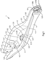
- a spring link 1 for a wheel suspension of a motor vehicle is shown.
- the spring link 1 has upwardly directed side legs 3, 4 connected to one another by a base 2 and is produced as a single-shell component from a metal plate by punching and reshaping. It has a first end section 1.1 for connection to a chassis beam and a second end section 1.2 for connection on the wheel side. Between the two end sections 1.1, 1.2 there is a spring receiving section 1.3, which has a spring support surface 2.1 formed on the bottom 2 for supporting a spring (helical spring) (not shown here). Furthermore, the spring link 1 between the spring receiving section 1.3 and the second end section 1.2 has a damper receiving section 1.4 for connecting a shock absorber (not shown).
- the spring link 1 is made of high-strength sheet metal, preferably high-strength sheet steel.
- the metal or steel sheet used for its production has a yield strength of at least 600 MPa, preferably at least 700 MPa, for example at least 800 MPa.
- the thickness of the metal or steel sheet used is, for example, in the range from 2.0 mm to 3.0 mm, preferably in the range from 2.0 mm to 2.6 mm.
- a U-shaped constriction 5 is formed, which runs in the base 2 and in the side legs 3, 4.
- the constriction 5 can be defined using reference planes.
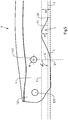
- the constriction 5 can be defined for example by a main plane (main reference plane) F1, a second plane E1 and a third plane D1, the main plane F1 running tangential to the underside of the base 2 opposite the spring support surface 2.1, the second plane E1 above and runs parallel to the main plane F1 and through the high point of the constriction 5 in the underside of the bottom 2, the third plane D1 parallel to the main plane F1 and through a Point of intersection S1 runs, the point of intersection S1 being the point of intersection of a straight line G with a lower outer contour line L of one of the side legs 4, and the straight line G perpendicular to the main plane F1 and through a center point M of one formed in the damper receiving section 1.4 serving to connect the shock absorber Mounting
- the constriction 5 is realized, for example, when the second plane E1 is spaced apart from the main plane F1 and the third plane D1 is spaced apart from the second plane E1.
- the constriction 5 is given when the distance A1 from the second plane E1 to the main plane F1 and the distance A2 from the third plane D1 to the second plane E1 are each greater than zero, the smaller distance A1 being the depth of the constriction 5 im Floor 2 corresponds.
- the depth of the constriction 5 in the base 2 of the spring link 1 can, for example, be in a range from 1.5 mm to 40 mm, in particular in a range from 8 mm to 16 mm.
- the distance A2 of the plane D1 to the plane E1 is preferably greater than the distance A1 of the second plane E1 to the main plane F1.
- the respective side leg 3, 4 of the spring link 1 defines an upper edge 3.1, 4.1.
- the distance between the upper edge 4.1 and the bottom 2 at the constriction 5 has a minimum.
- the side legs 3, 4 define mutually facing flanks 3.2, 4.2.
- the distance between the flanks 3.2, 4.2 from the upper edge 3.1, 4.1 in the direction of the base 2 gradually decreases.
- the mean distance A3 of the flanks 3.2, 4.2 from one another at the constriction 5 is smaller than the distance A4 between the flanks 3.2, 4.2 at the damper receiving section 1.4.
- the distance A3 of the flanks 3.2, 4.2 on the constriction 5 can be, for example, at least 3 mm, preferably at least 5 mm smaller than the distance A4 between the flanks 3.2, 4.2 on the damper receiving section 1.4.
- the spring link 1 is designed, for example, such that the distance A3 between the flanks 3.2, 4.2 at the constriction 5 is greater than the distance A5 between the flanks 3.2, 4.2 at the second end section 1.2.
- the distance A3 of the flanks 3.2, 4.2 at the constriction 5 can be at least 5 mm, preferably around be at least 8 mm greater than the distance A5 between the flanks 3.2, 4.2 at the second end section 1.2.
- the distance A3 of the flanks 3.2, 4.2 initially increases in the direction of the damper receiving section 1.4 and from a certain point in the direction of the fastening holes 1.41 formed in the side legs 3, 4, which are used to connect a shock absorber (not shown), from (cf. Fig. 1 and 3 ).
- the respective side leg 3, 4 of the spring link 1 has an outwardly projecting flange 3.3, 4.3 on its upper edge 3.1, 4.1.
- the flange 3.3, 4.3 extends essentially continuously from the first end section 1.1 to the second end section 1.2 of the spring link 1.
- the flange 3.3, 4.3 is of different widths along the respective side limbs 3, 4 and has its greatest width at the Constriction 5 (see Fig. 3 ).
- the flange 3.3, 4.3 has an outer edge 3.4, 4.4 which is beveled downward relative to its upper side. The downwardly curved outer edge 3.4, 4.4 extends essentially over the entire length of the flange 3.3, 4.3.
- the spring link 1 has a fork-shaped bearing section 1.21 defined by the side legs 3, 4, which additionally serves to connect a shock absorber.
- the fork-shaped bearing section 1.21 delimits a niche-shaped cutout 1.211 which extends from the second end section 1.2 to a point that lies between the fastening holes 1.41 and the constriction 5.
- flange-shaped, mutually facing webs 1.212 are formed which delimit the niche-shaped cutout 1.211.
- the spring support surface 2.1 has an opening 2.2 on which an inwardly protruding collar 2.3 is formed.
- the upper edge 2.31 of the collar 2.3 is preferably shaped radially inward, so that the upper, circumferential edge 2.32 of the Collar 2.3 protrudes radially inward relative to a lower annular portion of the collar 2.3.
- the side legs 3, 4 On the first end section 1.1 of the spring link 1, the side legs 3, 4 define a fork-shaped bearing section 1.11 for connecting the spring link to a chassis beam.
- the fork-shaped bearing section 1.11 has aligned openings 1.111 with a collar 1.112 for receiving a bearing bush.
- the collars 1.112 are preferably directed inward.
- the distance A6 between the side legs 3, 4 on the fork-shaped bearing section 1.11 is significantly smaller than the distance A5 between the side legs 3, 4 on the second end section 1.2 of the spring link 1.
- an elongated opening (passage opening) 2.5 is formed between the first end section 1.1 and the spring support surface 2.1, which extends essentially parallel to the longitudinal center axis of the spring link 1.
- the length of this opening 2.5 is significantly greater than the distance A4 between the flanks 3.2, 4.2 of the side legs 3, 4 on the damper receiving section 1.4.
- the longitudinal edges 2.51 of the opening 2.5 run essentially or in sections divergent to one another, their spacing increasing in the direction of the spring support surface 2.1.
- the design of the spring link 1 according to the invention is not limited to the exemplary embodiment shown in the drawing. Rather, numerous variants are conceivable which make use of the invention specified in the claims even in the case of designs that differ from the example shown.
- beads facing each other can be formed in the side legs 3, 4 between the damper receiving section 1.4 and the second end section 1.2.
- the beads are preferably designed such that the distance between the flanks 3.2, 4.2 of the side legs 3, 4 initially increases starting from the damper receiving section 1.4 in the direction of the second end section 1.2 and then decreases towards the fastening holes 1.23.
Abstract
Die Erfindung betrifft einen aus Metallblech geformten einschaligen Federlenker (1) für eine Radaufhängung eines Kraftfahrzeuges, mit nach oben gerichteten, durch einen Boden (2) miteinander verbundenen Seitenschenkeln (3, 4), mit einem ersten Endabschnitt (1.1) zur Anbindung an einem Fahrwerksträger, mit einem zweiten Endabschnitt (1.2) zur radseitigen Anbindung, mit einem Federaufnahmeabschnitt (1.3), der sich zwischen den beiden Endabschnitten (1.1, 1.2) befindet und eine auf dem Boden (2) gebildete Federabstützfläche (2.1) aufweist, und mit einem zwischen dem Federaufnahmeabschnitt (1.3) und dem zweiten Endabschnitt (1.2) ausgebildeten Dämpferaufnahmeabschnitt (1.4) zur Anbindung eines Stoßdämpfers. Um bei relativ geringem Bauteilgewicht sowie günstigen Herstellungskosten eine verbesserte Steifigkeit hinsichtlich hoher Achslasten zu erzielen, sieht die Erfindung vor, dass zwischen der Federabstützfläche (2.1) und dem Dämpferaufnahmeabschnitt (1.4) eine U-förmige Einschnürung (5) ausgebildet ist, die in dem Boden (2) und in den Seitenschenkeln (3, 4) verläuft.The invention relates to a single-shell spring link (1) formed from sheet metal for a wheel suspension of a motor vehicle, with upwardly directed side legs (3, 4) connected to one another by a base (2), with a first end section (1.1) for connection to a chassis beam , with a second end section (1.2) for the wheel-side connection, with a spring receiving section (1.3) which is located between the two end sections (1.1, 1.2) and has a spring support surface (2.1) formed on the bottom (2), and with a spring support surface (2.1) between the spring receiving section (1.3) and the second end section (1.2) formed damper receiving section (1.4) for connecting a shock absorber. In order to achieve improved rigidity with regard to high axle loads with a relatively low component weight and low manufacturing costs, the invention provides that a U-shaped constriction (5) is formed between the spring support surface (2.1) and the damper receiving section (1.4), which is formed in the floor (2) and in the side legs (3, 4).
Description
Die Erfindung betrifft einen aus Metallblech geformten einschaligen Federlenker für eine Radaufhängung eines Kraftfahrzeuges, mit nach oben gerichteten, durch einen Boden miteinander verbundenen Seitenschenkeln, mit einem ersten Endabschnitt zur Anbindung an einem Fahrwerksträger, mit einem zweiten Endabschnitt zur radseitigen Anbindung, mit einem Federaufnahmeabschnitt, der sich zwischen den beiden Endabschnitten befindet und eine auf dem Boden ausgebildete Federabstützfläche aufweist, und mit einem zwischen dem Federaufnahmeabschnitt und dem zweiten Endabschnitt ausgebildeten Dämpferaufnahmeabschnitt zur Anbindung eines Stoßdämpfers.The invention relates to a single-shell spring link formed from sheet metal for a wheel suspension of a motor vehicle, with upwardly directed side legs connected to one another by a floor, with a first end section for connection to a chassis beam, with a second end section for connection on the wheel side, with a spring receiving section which is located between the two end sections and has a spring support surface formed on the floor, and with a damper receiving section formed between the spring receiving section and the second end section for connecting a shock absorber.
Federlenker dienen der Führung eines Fahrwerkrades an einer Radaufhängung eines Kraftfahrzeuges. Sie weisen einen Abschnitt zur Abstützung einer Feder und einen Abschnitt zur Anbindung eines Stoßdämpfers oder alternativ einen Abschnitt zur Abstützung einer Feder-Stoßdämpfer-Anordnung auf, wobei die Feder bzw. Feder-Stoßdämpfer-Anordnung ihrerseits gegen die Karosserie abgestützt ist.Spring links are used to guide a chassis wheel on a wheel suspension of a motor vehicle. They have a section for supporting a spring and a section for connecting a shock absorber or, alternatively, a section for supporting a spring-shock absorber arrangement, the spring or spring-shock absorber arrangement in turn being supported against the body.
Ein Federlenker der oben genannten Art ist aus der
Eine bekannte Maßnahme zur Verbesserung der Steifigkeit, insbesondere der Biegesteifigkeit eines Federlenkers, der hohen Achslasten ausgesetzt ist, besteht in der Verwendung von Stahlblech höherer Materialstärke bei der Herstellung des Federlenkers. Eine Erhöhung der Materialstärke führt dabei jedoch zu einer erheblichen Gewichtszunahme pro Federlenker und höheren Materialkosten.A known measure for improving the rigidity, in particular the flexural rigidity of a spring link that is exposed to high axle loads, consists in the use of sheet steel of higher material thickness in the manufacture of the spring link. However, an increase in the material thickness leads to a considerable increase in weight per spring link and higher material costs.
Eine weitere bekannte Maßnahme zur Erzielung einer hohen Belastbarkeit des Federlenkers im Bereich der Federauflage ist das Anbringen von einem oder mehreren verstärkenden Zusatzblechen, insbesondere Brückenblechen (siehe z. B.
Davon ausgehend liegt der Erfindung die Aufgabe zugrunde, einen Federlenker der eingangs genannten Art zu schaffen, der bei relativ geringem Bauteilgewicht sowie günstigen Herstellungskosten eine verbesserte Steifigkeit hinsichtlich hoher Achslasten aufweist.On this basis, the invention is based on the object of creating a spring link of the type mentioned at the outset, which has an improved rigidity with regard to high axle loads with a relatively low component weight and low manufacturing costs.
Zur Lösung dieser Aufgabe wird ein Federlenker mit den in Anspruch 1 angegebenen Merkmalen vorgeschlagen. Vorteilhafte Ausgestaltungen des erfindungsgemäßen Federlenkers sind in den auf Anspruch 1 rückbezogenen Unteransprüchen angegeben.To solve this problem, a spring link with the features specified in
Der erfindungsgemäße einschalige Federlenker ist dadurch gekennzeichnet, dass zwischen der Federabstützfläche und dem Dämpferaufnahmeabschnitt eine U-förmige Einschnürung ausgebildet ist, die in dem Boden und in den Seitenschenkeln des Federlenkers verläuft. Die U-förmige Einschnürung kann auch als U-förmige Sicke bezeichnet werden.The single-shell spring link according to the invention is characterized in that a U-shaped constriction is formed between the spring support surface and the damper receiving section which runs in the bottom and in the side legs of the spring link. The U-shaped constriction can also be referred to as a U-shaped bead.
Durch die U-förmige Einschnürung (Sicke) lässt sich ein gattungsgemäßer Federlenker mit deutlich verbesserter Steifigkeit hinsichtlich hoher Achslasten erzielen. Da hierzu weder die Materialstärke des für die Herstellung des Federlenkers verwendeten Metallblechs erhöht werden muss noch Brückenbleche oder sonstige verstärkende Zusatzbleche an den Federlenker angefügt werden müssen, lässt sich der Federlenker mit relativ geringem Bauteilgewicht sowie günstigen Herstellungskosten bereitstellen.The U-shaped constriction (bead) makes it possible to achieve a spring link of the generic type with significantly improved rigidity with regard to high axle loads. Since neither the material thickness of the metal sheet used for the manufacture of the spring link has to be increased nor bridge plates or other reinforcing additional sheets have to be attached to the spring link, the spring link can be provided with a relatively low component weight and low manufacturing costs.
In einer bevorzugten Ausgestaltung des erfindungsgemäßen Federlenkers ist die Einschnürung durch eine Hauptebene, eine zweite Ebene und eine dritte Ebene definiert, wobei die Hauptebene tangential zu der der Federabstützfläche gegenüberliegende Unterseite des Bodens verläuft, wobei die zweite Ebene oberhalb und parallel zu der Hauptebene und durch den Hochpunkt der Einschnürung in der Unterseite des Bodens verläuft, wobei die dritte Ebene parallel zu der Hauptebene und durch einen Schnittpunkt verläuft, wobei der Schnittpunkt ein Schnittpunkt einer Geraden mit einer unteren Außenkonturlinie eines der Seitenschenkel ist, wobei die Gerade senkrecht zu der Hauptebene und durch einen Mittelpunkt eines im Dämpferaufnahmeabschnitt ausgebildeten, der Anbindung des Stoßdämpfers dienenden Befestigungsloches verläuft, und wobei die zweite Ebene relativ zu der Hauptebene und die dritte Ebene relativ zu der zweiten Ebene beabstandet sind.In a preferred embodiment of the spring link according to the invention, the constriction is defined by a main plane, a second plane and a third plane, the main plane running tangentially to the underside of the floor opposite the spring support surface, the second plane being above and parallel to the main plane and through the The high point of the constriction runs in the underside of the floor, the third plane running parallel to the main plane and through an intersection, the intersection being an intersection of a straight line with a lower outer contour line of one of the side legs, the straight line being perpendicular to the main plane and through a The center of a mounting hole which is formed in the damper receiving section and is used to connect the shock absorber runs, and wherein the second plane is spaced apart relative to the main plane and the third plane is spaced apart relative to the second plane.
Die dritte Ebene kann auch als Dämpferebene oder Dämpferreferenzebene bezeichnet werden. Die dritte Ebene (Dämpferebene) kann in, unterhalb oder oberhalb der Hauptebene verlaufen. Vorzugsweise ist der Abstand der dritten Ebene zu der zweiten Ebene größer als der Abstand der zweiten Ebene zu der Hauptebene.The third level can also be referred to as the damper level or damper reference level. The third level (damper level) can run in, below or above the main level. The distance between the third plane and the second plane is preferably greater than the distance between the second plane and the main plane.
Soweit in der vorliegenden Beschreibung des erfindungsgemäßen Federlenkers die Begriffe "oben", "oberhalb", "unterhalb", "Unterseite" und/oder "Hochpunkt" verwendet werden, beziehen sich diese Begriffe auf die übliche Einbaulage des Federlenkers. Insbesondere ist mit dem Ausdruck "Hochpunkt der Einschnürung in der Unterseite des Bodens" die Stelle der Einschnürung in der Unterseite des Bodens des Federlenkers gemeint, wo die Einschnürung in der üblichen Einbaulage des Federlenkers ihre größte Profiltiefe in der Unterseite des Bodens des Federlenkers aufweist.Insofar as the terms “above”, “above”, “below”, “underside” and / or “high point” are used in the present description of the spring link according to the invention, these terms refer to the usual installation position of the spring link. In particular, the expression "high point of the constriction in the underside of the floor "means the point of constriction in the underside of the floor of the spring link, where the constriction has its greatest profile depth in the underside of the floor of the spring link in the usual installation position of the spring link.
Eine weitere Ausgestaltung des erfindungsgemäßen Federlenkers, dessen jeweiliger Seitenschenkel eine Oberkante definiert, ist dadurch gekennzeichnet, dass der Abstand der Oberkante relativ zu dem Boden an der Einschnürung ein Minimum hat. Diese Ausgestaltung hat sich als sehr vorteilhaft erwiesen, um einen erfindungsgemäßen Federlenker zu erzielen, der bei relativ geringem Bauteilgewicht sowie günstigen Herstellungskosten eine verbesserte Steifigkeit hinsichtlich hoher Achslasten aufweist.Another embodiment of the spring link according to the invention, the respective side leg of which defines an upper edge, is characterized in that the distance between the upper edge and the floor at the constriction has a minimum. This configuration has proven to be very advantageous in order to achieve a spring link according to the invention which has improved rigidity with regard to high axle loads with a relatively low component weight and low manufacturing costs.
Eine weitere vorteilhafte Ausgestaltung des Federlenkers, dessen Seitenschenkel einander zugewandte Flanken definieren, ist dadurch gekennzeichnet, dass der Abstand der Flanken zueinander an der Einschnürung kleiner ist als der Abstand der Flanken zueinander am Dämpferaufnahmeabschnitt. Auch diese Ausgestaltung trägt zu einer verbesserten Steifigkeit hinsichtlich hoher Achslasten bei, insbesondere dann, wenn der Abstand der Flanken zueinander an der Einschnürung um mindestens 3 mm, vorzugsweise um mindestens 5 mm kleiner ist als der Abstand der Flanken zueinander am Dämpferaufnahmeabschnitt.Another advantageous embodiment of the spring link, the side legs of which define flanks facing each other, is characterized in that the distance between the flanks at the constriction is smaller than the distance between the flanks at the damper receiving section. This configuration also contributes to improved rigidity with regard to high axle loads, especially when the distance between the flanks at the constriction is at least 3 mm, preferably at least 5 mm less than the distance between the flanks at the damper receiving section.
Des Weiteren hat es sich als günstig für eine hohe Steifigkeit des Federlenkers bei konstantem oder geringem Bauteilgewicht herausgestellt, wenn nach einer weiteren Ausgestaltung des Federlenkers der Abstand seiner Flanken zueinander an der Einschnürung größer ist als der Abstand der Flanken zueinander am zweiten Endabschnitt des Federlenkers. Diesbezüglich wird insbesondere vorgeschlagen, dass der Abstand der Flanken zueinander an der Einschnürung um mindestens 5 mm, vorzugsweise um mindestens 8 mm größer ist als der Abstand der Flanken zueinander am zweiten Endabschnitt.Furthermore, it has proven to be favorable for a high stiffness of the spring link with constant or low component weight if, according to a further embodiment of the spring link, the distance between its flanks at the constriction is greater than the distance between the flanks at the second end section of the spring link. In this regard, it is proposed in particular that the distance between the flanks at the constriction is at least 5 mm, preferably at least 8 mm greater than the distance between the flanks at the second end section.
Nach einer alternativen Ausgestaltung des Federlenkers kann der Abstand seiner Flanken zueinander an der Einschnürung auch kleiner als oder gleich dem Abstand der Flanken zueinander am zweiten Endabschnitt des Federlenkers sein. Beispielsweise kann der Abstand der Flanken zueinander an der Einschnürung um mindestens 3 mm, vorzugsweise um mindestens 5 mm kleiner sein als der Abstand der Flanken zueinander am zweiten Endabschnitt.According to an alternative embodiment of the spring link, the distance between its flanks at the constriction can also be smaller than or equal to the distance between the flanks at the second end section of the spring link. For example, the distance between the flanks at the constriction can be at least 3 mm, preferably at least 5 mm smaller than the distance between the flanks at the second end section.
Um eine kritische Aufweitung oder Verformung der Seitenschenkel des Federlenkers infolge hoher Achslasten in z-Richtung (Fahrzeughochachse) weitestgehend zu verhindern, ohne dabei das Bauteilgewicht des Federlenkers zu erhöhen, sieht eine weitere Ausgestaltung der Erfindung vor, dass eine Tiefe (Profiltiefe) der Einschnürung relativ zu der oben genannten Hauptebene im Bereich von 1,5 mm bis 40 mm, vorzugsweise im Bereich von 5 mm bis 40 mm, besonders bevorzugt im Bereich von 10 mm bis 40 mm liegt.In order to largely prevent critical widening or deformation of the side legs of the spring link as a result of high axle loads in the z-direction (vehicle vertical axis) without increasing the component weight of the spring link, a further embodiment of the invention provides that a depth (profile depth) of the constriction is relative to the above-mentioned main plane in the range from 1.5 mm to 40 mm, preferably in the range from 5 mm to 40 mm, particularly preferably in the range from 10 mm to 40 mm.
Eine weitere Ausgestaltung der Erfindung sieht vor, dass eine Tiefe (Profiltiefe) der Einschnürung relativ zu der oben genannten dritten Ebene (Dämpferebene) im Bereich von 1,5 mm bis 45 mm, vorzugsweise im Bereich von 5 mm bis 45 mm, besonders bevorzugt im Bereich von 10 mm bis 45 mm liegt.Another embodiment of the invention provides that a depth (profile depth) of the constriction relative to the above-mentioned third level (damper level) in the range from 1.5 mm to 45 mm, preferably in the range from 5 mm to 45 mm, particularly preferably in Range from 10 mm to 45 mm.
Nach einer weiteren Ausgestaltung des erfindungsgemäßen Federlenkers nimmt der Abstand der Flanken ausgehend von der Einschnürung zu dem Dämpferaufnahmeabschnitt hin zunächst zu und anschließend in Richtung von in den Seitenschenkeln ausgebildeten Befestigungslöchern, die der Anbindung des Stoßdämpfers dienen, hin ab. Hierdurch wird die Steifigkeit des relativ leichtgewichtigen Federlenkers bei günstigen Herstellungskosten weiter verbessert.According to a further embodiment of the spring link according to the invention, the distance between the flanks initially increases starting from the constriction to the damper receiving section and then decreases in the direction of fastening holes formed in the side legs, which are used to connect the shock absorber. This further improves the rigidity of the relatively lightweight spring link at low manufacturing costs.
Eine weitere vorteilhafte Ausgestaltung des erfindungsgemäßen Federlenkers ist dadurch gekennzeichnet, dass der jeweilige Seitenschenkel an seiner Oberkante einen nach außen vorstehenden Flansch aufweist, der entlang des Seitenschenkels unterschiedlich breit ausgebildet ist und seine größte Breite an der Einschnürung aufweist. Hierdurch wird die Steifigkeit des Federlenkers gegen eine Aufweitung oder eine Verformung der Seitenschenkel bei hoher Achslast weiter optimiert. Vorzugsweise erstreckt sich der Flansch des jeweiligen Seitenschenkels von dem ersten Endabschnitt durchgängig bis zu dem zweiten Endabschnitt des Federlenkers. Eine noch höhere Steifigkeit des Federlenkers lässt sich erzielen, wenn nach einer weiteren Ausgestaltung des Federlenkers der Flansch einen relativ zu seiner Oberseite nach unten hin abgekanteten Außenrand aufweist, der sich zumindest entlang des Federaufnahmeabschnitt und des Dämpferaufnahmeabschnitt erstreckt.Another advantageous embodiment of the spring link according to the invention is characterized in that the respective side limb has an outwardly protruding flange on its upper edge, which is of different widths along the side limb and its greatest width at the constriction having. This further optimizes the stiffness of the spring link against expansion or deformation of the side legs when the axle load is high. The flange of the respective side limb preferably extends continuously from the first end section to the second end section of the spring link. An even greater rigidity of the spring link can be achieved if, according to a further embodiment of the spring link, the flange has an outer edge which is beveled downward relative to its upper side and which extends at least along the spring receiving section and the damper receiving section.
In einer weiteren vorteilhaften Ausgestaltung des Federlenkers definieren die Seitenschenkel einen gabelförmigen Lagerabschnitt zur Anbindung eines Radträgers sowie zur Anbindung des Stoßdämpfers. Der gabelförmige Lagerabschnitt begrenzt dabei einen nischenförmigen Ausschnitt, der sich von dem zweiten Endabschnitt bis zu einer Stelle, die zwischen Befestigungslöchern, die der Anbindung des Stoßdämpfers dienen, und der Einschnürung liegt, erstreckt. Die Anbindung des Stoßdämpfers an den Seitenschenkeln des Federlenkers erhöht die Steifigkeit des Stoßdämpfers gegen eine Aufweitung der Seitenschenkel. Der nischenförmige Ausschnitt in dem gabelförmigen Lagerabschnitt verringert das Bauteilgewicht des Federlenkers.In a further advantageous embodiment of the spring link, the side legs define a fork-shaped bearing section for connecting a wheel carrier and for connecting the shock absorber. The fork-shaped bearing section delimits a niche-shaped cutout which extends from the second end section to a point which lies between the fastening holes, which are used to connect the shock absorber, and the constriction. The connection of the shock absorber to the side legs of the spring link increases the rigidity of the shock absorber against expansion of the side legs. The niche-shaped cutout in the fork-shaped bearing section reduces the component weight of the spring link.
Für die Steifigkeit des relativ leichtgewichtigen Federlenkers ist es auch vorteilhaft, wenn nach einer weiteren Ausgestaltung an dem gabelförmigen Lagerabschnitt flanschförmige, einander zugewandte Stege ausgebildet sind, welche den nischenförmigen Ausschnitt begrenzen.For the rigidity of the relatively lightweight spring link, it is also advantageous if, according to a further embodiment, flange-shaped, mutually facing webs are formed on the fork-shaped bearing section, which delimit the niche-shaped cutout.
In einer weiteren vorteilhaften Ausgestaltung des Federlenkers weist dessen Federabstützfläche eine Öffnung auf, an der ein einwärts vorstehender Kragen ausgebildet ist. Im montierten Zustand des Federlenkers ragt der Kragen in die auf der Federabstützfläche abgestützte Feder (Schraubenfeder). Vorzugsweise ist der obere Rand des Kragens radial nach innen geformt, so dass die obere, umlaufende Kante des Kragens radial nach innen gegenüber einem unteren ringförmigen Abschnitt des Kragens vorsteht. Der Kragen kann als Zentriervorsprung für die auf dem Federlenker abgestützte Feder dienen. Zudem verbessert der Kragen die Steifigkeit des Federlenkers.In a further advantageous embodiment of the spring link, its spring support surface has an opening on which an inwardly protruding collar is formed. In the assembled state of the spring link, the collar protrudes into the spring (helical spring) supported on the spring support surface. Preferably, the upper edge of the collar is formed radially inward, so that the upper, circumferential edge of the collar is radially inwardly opposite a lower annular portion of the Collar protrudes. The collar can serve as a centering projection for the spring supported on the spring link. In addition, the collar improves the stiffness of the spring link.
Eine weitere Ausgestaltung des Federlenkers sieht vor, dass in den Seitenschenkeln zwischen dem Dämpferaufnahmeabschnitt und dem zweiten Endabschnitt einander zugewandte Sicken ausgebildet sind. Die Sicken sind dabei so ausgebildet, dass der Abstand der Flanken der Seitenschenkel ausgehend von dem Dämpferaufnahmeabschnitt in Richtung des zweiten Endabschnitts zunächst zunimmt und anschließend zu Befestigungslöchern, die der Anbindung eines Radträgers dienen, hin abnimmt. Durch diese Sicken wird die Steifigkeit des Federlenkers bei relativ geringem Bauteilgewicht sowie günstigen Herstellungskosten weiter verbessert.Another embodiment of the spring link provides that beads facing each other are formed in the side legs between the damper receiving section and the second end section. The beads are designed in such a way that the distance between the flanks of the side legs, starting from the damper receiving section, initially increases in the direction of the second end section and then decreases towards fastening holes that are used to connect a wheel carrier. These beads further improve the rigidity of the spring link with a relatively low component weight and low manufacturing costs.
Eine weitere vorteilhafte Ausgestaltung des Federlenkers ist dadurch gekennzeichnet, dass die Seitenschenkel an dem ersten Endabschnitt des Federlenkers einen gabelförmigen Lagerabschnitt zur Anbindung des Federlenkers an einem Fahrwerksträger definieren, wobei der gabelförmige Lagerabschnitt miteinander fluchtende Öffnungen mit Kragen zur Aufnahme einer Lagerbuchse aufweist. Die Kragen, die auch als Durchzüge bezeichnet werden können, sind vorzugsweise nach innen gerichtet, d. h. einander zugewandt.A further advantageous embodiment of the spring link is characterized in that the side legs on the first end section of the spring link define a fork-shaped bearing section for connecting the spring link to a chassis beam, the fork-shaped bearing section having aligned openings with collars for receiving a bearing bush. The collars, which can also be referred to as passages, are preferably directed inwards, i. H. facing each other.
Nach einer weiteren vorteilhaften Ausgestaltung des Federlenkers ist im Boden des Federlenkers zwischen der Federabstützfläche und dem ersten Endabschnitt, welcher der Anbindung des Federlenkers an einem Fahrwerksträger dient, eine längliche Öffnung ausgebildet, die sich im Wesentlichen parallel zur Längsmittelachse des Federlenkers erstreckt. Die Länge dieser Öffnung ist vorzugsweise deutlich größer als der Abstand der Flanken der Seitenschenkel an der Einschnürung oder am Dämpferaufnahmeabschnitt und/oder als der Durchmesser der in der Federabstützfläche ausgebildeten Öffnung. Die Längskanten der länglichen Öffnung verlaufen vorzugsweise im Wesentlichen oder abschnittsweise divergent zueinander, wobei ihr Abstand in Richtung der Federabstützfläche hin zunimmt. Durch die längliche Öffnung wird das Bauteilgewicht des Federlenkers erheblich reduziert.According to a further advantageous embodiment of the spring link, an elongated opening is formed in the bottom of the spring link between the spring support surface and the first end section, which is used to connect the spring link to a chassis beam, which extends essentially parallel to the longitudinal center axis of the spring link. The length of this opening is preferably significantly greater than the distance between the flanks of the side legs on the constriction or on the damper receiving section and / or than the diameter of the opening formed in the spring support surface. The longitudinal edges of the elongated opening preferably run substantially or in sections divergent to one another, their spacing increases in the direction of the spring support surface. The elongated opening significantly reduces the component weight of the spring link.
Der erfindungsgemäße Federlenker ist nach einer weiteren Ausgestaltung der Erfindung aus Stahlblech mit einer Streckgrenze von mindestens 600 MPa, vorzugsweise mindestens 700 MPa, besonders bevorzugt mindestens 750 MPa hergestellt.According to a further embodiment of the invention, the spring link according to the invention is made of sheet steel with a yield point of at least 600 MPa, preferably at least 700 MPa, particularly preferably at least 750 MPa.
Nachfolgend wird die Erfindung anhand einer ein Ausführungsbeispiel darstellenden Zeichnung näher erläutert. Es zeigen:
- Fig. 1
- einen erfindungsgemäßen Federlenker in einer perspektivischen Darstellung;
- Fig. 2
- den Federlenker aus
Fig. 1 in einer Seitenansicht; - Fig. 3
- den Federlenker aus
Fig. 1 in einer Draufsicht; - Fig. 4A
- eine Querschnittansicht des Federlenkers entlang der Schnittlinie IVA-IVA in
Fig. 3 ; - Fig. 4B
- eine Querschnittansicht des Federlenkers entlang der Schnittlinie IVB-IVB in
Fig. 3 ; - Fig. 4C
- die Querschnittansicht der
Fig. 4B überlagert mit der Querschnittansicht derFig. 4A ; und - Fig. 5
- eine vereinfachte Seitenansicht eines Abschnitts des Federlenkers aus
Fig. 2 , mit dem Endanschnitt zur radseitigen Anbindung des Federlenkers, dem Dämpferaufnahmeabschnitt zur Anbindung eines Stoßdämpfers und der U-förmigen Einschnürung.
- Fig. 1
- a spring link according to the invention in a perspective view;
- Fig. 2
- the spring link off
Fig. 1 in a side view; - Fig. 3
- the spring link off
Fig. 1 in a plan view; - Figure 4A
- a cross-sectional view of the spring link along the section line IVA-IVA in
Fig. 3 ; - Figure 4B
- a cross-sectional view of the spring link along the section line IVB-IVB in
Fig. 3 ; - Figure 4C
- the cross-sectional view of the
Figure 4B superimposed with the cross-sectional view of theFigure 4A ; and - Fig. 5
- a simplified side view of a portion of the spring link
Fig. 2 , with the end cut for the wheel-side connection of the spring link, the damper receiving section for the connection of a shock absorber and the U-shaped constriction.
In der Zeichnung ist ein Federlenker 1 für eine Radaufhängung eines Kraftfahrzeuges dargestellt. Der Federlenker 1 weist nach oben gerichtete, durch einen Boden 2 miteinander verbundene Seitenschenkel 3, 4 auf und ist als einschaliges Bauteil aus einer Metallplatine durch Ausstanzen und Umformen hergestellt. Er hat einen ersten Endabschnitt 1.1 zur Anbindung an einem Fahrwerksträger und einen zweiten Endabschnitt 1.2 zur radseitigen Anbindung. Zwischen den beiden Endabschnitten 1.1, 1.2 befindet sich ein Federaufnahmeabschnitt 1.3, der eine auf dem Boden 2 ausgebildete Federabstützfläche 2.1 zur Abstützung einer (hier nicht gezeigten) Feder (Schraubenfeder) aufweist. Des Weiteren weist der Federlenker 1 zwischen dem Federaufnahmeabschnitt 1.3 und dem zweiten Endabschnitt 1.2 einen Dämpferaufnahmeabschnitt 1.4 zur Anbindung eines Stoßdämpfers (nicht gezeigt) auf.In the drawing, a
Der Federlenker 1 ist aus hochfestem Metallblech, vorzugsweise hochfestem Stahlblech hergestellt. Das zu seiner Herstellung verwendete Metall- oder Stahlblech hat eine Streckgrenze von mindestens 600 MPa, vorzugsweise mindestens 700 MPa, beispielsweise von mindestens 800 MPa. Die Dicke des verwendeten Metall- oder Stahlblechs liegt beispielsweise im Bereich von 2,0 mm bis 3,0 mm, vorzugsweise im Bereich von 2,0 mm bis 2,6 mm.The
Zwischen der Federabstützfläche 2.1 und dem Dämpferaufnahmeabschnitt 1.4 ist eine U-förmige Einschnürung 5 ausgebildet, die in dem Boden 2 und in den Seitenschenkeln 3, 4 verläuft. Die Einschnürung 5 lässt sich anhand von Referenzebenen definieren. Wie in
Der jeweilige Seitenschenkel 3, 4 des Federlenkers 1 definiert eine Oberkante 3.1, 4.1. In
Ferner ist der Federlenker 1 beispielsweise derart ausgebildet, dass der Abstand A3 der Flanken 3.2, 4.2 an der Einschnürung 5 größer ist als der Abstand A5 der Flanken 3.2, 4.2 an dem zweiten Endabschnitt 1.2. Beispielsweise kann der Abstand A3 der Flanken 3.2, 4.2 an der Einschnürung 5 um mindestens 5 mm, vorzugsweise um mindestens 8 mm größer sein als der Abstand A5 der Flanken 3.2, 4.2 an dem zweiten Endabschnitt 1.2.Furthermore, the
Ausgehend von der Einschnürung 5 nimmt der Abstand A3 der Flanken 3.2, 4.2 in Richtung zu dem Dämpferaufnahmeabschnitt 1.4 hin zunächst zu und von einer gewissen Stelle aus in Richtung zu den in den Seitenschenkeln 3, 4 ausgebildeten Befestigungslöchern 1.41, die der Anbindung eines Stoßdämpfers (nicht gezeigt) dienen, ab (vgl.
Der jeweilige Seitenschenkel 3, 4 des Federlenkers 1 weist an seiner Oberkante 3.1, 4.1 einen nach außen vorstehenden Flansch 3.3, 4.3 auf. Vorzugsweise erstreckt sich der Flansch 3.3, 4.3 im Wesentlichen von dem ersten Endabschnitt 1.1 aus kontinuierlich bis zu dem zweiten Endabschnitt 1.2 des Federlenkers 1. Der Flansch 3.3, 4.3 ist entlang des jeweiligen Seitenschenkels 3, 4 unterschiedlich breit ausgebildet und besitzt seine größte Breite an der Einschnürung 5 (siehe
An seinem der Anbindung eines Radträgers dienenden Endabschnitt 1.2 weist der Federlenker 1 einen durch die Seitenschenkel 3, 4 definierten gabelförmigen Lagerabschnitt 1.21 auf, der zusätzlich der Anbindung eines Stoßdämpfers dient. Der gabelförmige Lagerabschnitt 1.21 begrenzt einen nischenförmigen Ausschnitt 1.211, der sich von dem zweiten Endabschnitt 1.2 bis zu einer Stelle, die zwischen Befestigungslöchern 1.41 und der Einschnürung 5 liegt, erstreckt. An dem Lagerabschnitt 1.21 sind flanschförmige, einander zugewandte Stege 1.212 ausgebildet, die den nischenförmigen Ausschnitt 1.211 begrenzen.At its end section 1.2 serving to connect a wheel carrier, the
Die Federabstützfläche 2.1 weist eine Öffnung 2.2 auf, an der ein einwärts vorstehender Kragen 2.3 ausgebildet ist. Der obere Rand 2.31 des Kragens 2.3 ist vorzugsweise radial nach innen geformt, so dass die obere, umlaufende Kante 2.32 des Kragens 2.3 radial nach innen gegenüber einem unteren ringförmigen Abschnitt des Kragens 2.3 vorsteht.The spring support surface 2.1 has an opening 2.2 on which an inwardly protruding collar 2.3 is formed. The upper edge 2.31 of the collar 2.3 is preferably shaped radially inward, so that the upper, circumferential edge 2.32 of the Collar 2.3 protrudes radially inward relative to a lower annular portion of the collar 2.3.
An dem ersten Endabschnitt 1.1 des Federlenkers 1 definieren die Seitenschenkel 3, 4 einen gabelförmigen Lagerabschnitt 1.11 zur Anbindung des Federlenkers an einem Fahrwerksträger. Der gabelförmige Lagerabschnitt 1.11 weist miteinander fluchtende Öffnungen 1.111 mit Kragen 1.112 zur Aufnahme einer Lagerbuchse auf. Die Kragen 1.112 sind vorzugsweise nach innen gerichtet. Der Abstand A6 der Seitenschenkel 3, 4 an dem gabelförmige Lagerabschnitt 1.11 ist deutlich kleiner als der Abstand A5 der Seitenschenkel 3, 4 an dem zweiten Endabschnitt 1.2 des Federlenkers 1.On the first end section 1.1 of the
Im Boden 2 des Federlenkers 1 ist zwischen dem ersten Endabschnitt 1.1 und der Federabstützfläche 2.1 eine längliche Öffnung (Durchgangsöffnung) 2.5 ausgebildet, die sich im Wesentlichen parallel zur Längsmittelachse des Federlenkers 1 erstreckt. Die Länge dieser Öffnung 2.5 ist deutlich größer als der Abstand A4 der Flanken 3.2, 4.2 der Seitenschenkel 3, 4 am Dämpferaufnahmeabschnitt 1.4. Die Längskanten 2.51 der Öffnung 2.5 verlaufen im Wesentlichen oder abschnittsweise divergent zueinander, wobei ihr Abstand in Richtung der Federabstützfläche 2.1 hin zunimmt.In the
Die Ausführung des erfindungsgemäßen Federlenkers 1 ist nicht auf das in der Zeichnung dargestellte Ausführungsbeispiel beschränkt. Vielmehr sind zahlreiche Varianten denkbar, die auch bei von dem gezeigten Beispiel abweichenden Ausführungen von der in den Ansprüchen angegebenen Erfindung Gebrauch machen. So können beispielsweise in den Seitenschenkeln 3, 4 zwischen dem Dämpferaufnahmeabschnitt 1.4 und dem zweiten Endabschnitt 1.2 einander zugewandte Sicken ausgebildet sein. Die Sicken sind dabei vorzugsweise so ausgebildet, dass der Abstand der Flanken 3.2, 4.2 der Seitenschenkel 3, 4 ausgehend von dem Dämpferaufnahmeabschnitt 1.4 in Richtung des zweiten Endabschnitts 1.2 zunächst zunimmt und anschließend zu den Befestigungslöchern 1.23 hin abnimmt.The design of the
Claims (15)
wobei die dritte Ebene (D1) parallel zu der Hauptebene (F1) und durch einen Schnittpunkt (S1) verläuft,
wobei der Schnittpunkt (S1) ein Schnittpunkt einer Geraden (G) mit einer unteren Außenkonturlinie (L) eines der Seitenschenkel (3, 4) ist,
wobei die Gerade (G) senkrecht zu der Hauptebene (F1) und durch einen Mittelpunkt (M) eines im Dämpferaufnahmeabschnitt (1.4) ausgebildeten, der Anbindung des Stoßdämpfers dienenden Befestigungsloches (1.41) verläuft, und wobei die zweite Ebene (E1) relativ zu der Hauptebene (F1) und die dritte Ebene (D1) relativ zu der zweiten Ebene (E1) beabstandet sind.Spring link according to claim 1, characterized in that the constriction (5) is defined by a main plane (F1), a second plane (E1) and a third plane (D1), the main plane (F1) being tangential to that of the spring support surface (2.1 ) the opposite underside of the base (2) runs, the second level (E1) running above and parallel to the main plane (F1) and through the high point of the constriction (5) in the underside of the base (2),
wherein the third plane (D1) runs parallel to the main plane (F1) and through an intersection (S1),
wherein the point of intersection (S1) is an intersection of a straight line (G) with a lower outer contour line (L) of one of the side legs (3, 4),
wherein the straight line (G) runs perpendicular to the main plane (F1) and through a center point (M) of a fastening hole (1.41) formed in the damper receiving section (1.4) and serving to connect the shock absorber, and the second plane (E1) relative to the The main plane (F1) and the third plane (D1) are spaced apart relative to the second plane (E1).
Priority Applications (3)
| Application Number | Priority Date | Filing Date | Title |
|---|---|---|---|
| EP19168696.3A EP3722121B1 (en) | 2019-04-11 | 2019-04-11 | One-shell suspension arm |
| US16/840,608 US11254175B2 (en) | 2019-04-11 | 2020-04-06 | Single-shell spring control arm |
| CN202010265244.8A CN111806182B (en) | 2019-04-11 | 2020-04-07 | Single shell type spring control arm |
Applications Claiming Priority (1)
| Application Number | Priority Date | Filing Date | Title |
|---|---|---|---|
| EP19168696.3A EP3722121B1 (en) | 2019-04-11 | 2019-04-11 | One-shell suspension arm |
Publications (2)
| Publication Number | Publication Date |
|---|---|
| EP3722121A1 true EP3722121A1 (en) | 2020-10-14 |
| EP3722121B1 EP3722121B1 (en) | 2021-11-24 |
Family
ID=66105215
Family Applications (1)
| Application Number | Title | Priority Date | Filing Date |
|---|---|---|---|
| EP19168696.3A Active EP3722121B1 (en) | 2019-04-11 | 2019-04-11 | One-shell suspension arm |
Country Status (3)
| Country | Link |
|---|---|
| US (1) | US11254175B2 (en) |
| EP (1) | EP3722121B1 (en) |
| CN (1) | CN111806182B (en) |
Families Citing this family (12)
| Publication number | Priority date | Publication date | Assignee | Title |
|---|---|---|---|---|
| WO2020010199A1 (en) * | 2018-07-05 | 2020-01-09 | Shiloh Industries, Inc. | Vehicle suspension component with stiffening feature |
| DE112019004182T5 (en) * | 2018-08-20 | 2021-06-10 | Grouper Stamping, Llc | VEHICLE SUSPENSION COMPONENT WITH REINFORCEMENT FEATURE AND CONNECTION ATTACHMENT |
| USD951149S1 (en) | 2019-10-31 | 2022-05-10 | Traxxas, L.P. | Model vehicle upper suspension arm |
| USD951148S1 (en) | 2019-10-31 | 2022-05-10 | Traxxas, L.P. | Model vehicle lower suspension arm |
| USD951150S1 (en) | 2019-10-31 | 2022-05-10 | Traxxas, L.P. | Model vehicle lower suspension arm |
| USD951151S1 (en) | 2019-10-31 | 2022-05-10 | Traxxas, L.P. | Model vehicle lower suspension arm |
| USD947957S1 (en) | 2019-12-11 | 2022-04-05 | Traxxas Lp | Model vehicle upper suspension arm |
| DE102020212778A1 (en) * | 2020-10-09 | 2022-04-14 | Zf Friedrichshafen Ag | Chassis component with at least one connection section for connection to a fastening section of a chassis element |
| JP2022154817A (en) * | 2021-03-30 | 2022-10-13 | マツダ株式会社 | Suspension device of automobile |
| CN113525002A (en) * | 2021-07-30 | 2021-10-22 | 岚图汽车科技有限公司 | Compatible spring arm |
| USD1014655S1 (en) | 2021-11-16 | 2024-02-13 | Traxxas, L.P. | Model vehicle suspension arm |
| USD1014656S1 (en) | 2021-11-16 | 2024-02-13 | Traxxas, L.P. | Model vehicle suspension arm |
Citations (5)
| Publication number | Priority date | Publication date | Assignee | Title |
|---|---|---|---|---|
| GB2198398A (en) * | 1986-12-09 | 1988-06-15 | Honda Motor Co Ltd | Rear suspension system for automobiles |
| DE102004008957A1 (en) | 2004-02-24 | 2005-09-01 | Volkswagen Ag | Vehicle suspension arm for damper mounting has a pressed profile with bracing cross strips to prevent deformation of the arm |
| EP1642754A1 (en) * | 2003-07-03 | 2006-04-05 | Toyota Jidosha Kabushiki Kaisha | Suspension arm |
| DE102011000462A1 (en) | 2011-02-02 | 2012-08-16 | Gmf Umformtechnik Gmbh | Single-leaf spring link |
| DE102014118518A1 (en) | 2014-12-12 | 2016-06-16 | Benteler Automobiltechnik Gmbh | Multi-part spring link |
Family Cites Families (22)
| Publication number | Priority date | Publication date | Assignee | Title |
|---|---|---|---|---|
| DE19827864C1 (en) * | 1998-06-08 | 2000-01-27 | Porsche Ag | Wheel suspension for a motor vehicle |
| JP4360227B2 (en) * | 2004-02-19 | 2009-11-11 | マツダ株式会社 | Suspension device |
| KR20060120731A (en) * | 2005-05-23 | 2006-11-28 | 현대모비스 주식회사 | Spring sheet assembly and lower arm assembly for vehicle using the same |
| DE102006014730A1 (en) * | 2006-03-30 | 2007-10-04 | Volkswagen Ag | One-piece spring-loaded wheel fork for an automobile wheel suspension produced by deep drawing from a light structural steel disk useful in automobile construction is weight optimised and can be produced at low cost |
| KR20080052760A (en) * | 2006-12-08 | 2008-06-12 | 현대자동차주식회사 | Lower spring seat adjusting device in suspension system |
| US7959171B2 (en) * | 2007-11-26 | 2011-06-14 | Nissan Motor Co., Ltd. | Lower spring seat mounting structure for vehicle suspension |
| DE102008013182A1 (en) * | 2008-03-07 | 2009-09-17 | Benteler Automobiltechnik Gmbh | Guide rod component i.e. spring-loaded control rod for wheel suspension of all-terrain vehicle, has base body provided with end sections, where each end section comprises set of side pieces and open sides |
| JP5299470B2 (en) * | 2011-05-16 | 2013-09-25 | 日産自動車株式会社 | Suspension structure and suspension link forming method |
| JP5877068B2 (en) * | 2012-01-05 | 2016-03-02 | 本田技研工業株式会社 | Spring seat |
| DE102012100719A1 (en) * | 2012-01-30 | 2013-08-01 | Gmf Umformtechnik Gmbh | Single-leaf spring link |
| EP2818342A4 (en) * | 2012-02-21 | 2014-12-31 | Yorozu Jidosha Kogyo Kk | Vehicle suspension arm |
| DE102012214352A1 (en) * | 2012-08-13 | 2014-02-13 | Zf Friedrichshafen Ag | independent suspension |
| DE102013225083A1 (en) * | 2013-12-06 | 2015-06-11 | Bayerische Motoren Werke Aktiengesellschaft | Underbody paneling for a two-lane motor vehicle and two-lane motor vehicle with such an underbody paneling |
| EP2910454B1 (en) * | 2014-02-20 | 2016-08-17 | Autotech Engineering Deutschland GmbH | Undercarriage component with eccentric disc stop |
| KR102300647B1 (en) * | 2014-10-30 | 2021-09-10 | 현대모비스 주식회사 | Suspention Of Multilink |
| DE102016100666A1 (en) * | 2016-01-15 | 2017-07-20 | Benteler Automobiltechnik Gmbh | Spring link made of steel |
| DE102017117309A1 (en) * | 2017-07-31 | 2019-01-31 | Benteler Automobiltechnik Gmbh | Handlebar and method of manufacturing a handlebar |
| EP3530497B1 (en) * | 2018-02-27 | 2020-04-15 | Autotech Engineering Deutschland GmbH | Undercarriage component with eccentric disc stop and method for producing an undercarriage component |
| EP3543044B1 (en) * | 2018-03-21 | 2020-08-05 | Autotech Engineering Deutschland GmbH | Suspension arm with damper connecting section and method for producing a suspension arm |
| DE102019108548B4 (en) * | 2019-04-02 | 2023-12-28 | Benteler Automobiltechnik Gmbh | Spring handlebars |
| KR20220127660A (en) * | 2021-03-11 | 2022-09-20 | 현대자동차주식회사 | Suspension for vehicle |
| CN113525002A (en) * | 2021-07-30 | 2021-10-22 | 岚图汽车科技有限公司 | Compatible spring arm |
-
2019
- 2019-04-11 EP EP19168696.3A patent/EP3722121B1/en active Active
-
2020
- 2020-04-06 US US16/840,608 patent/US11254175B2/en active Active
- 2020-04-07 CN CN202010265244.8A patent/CN111806182B/en active Active
Patent Citations (5)
| Publication number | Priority date | Publication date | Assignee | Title |
|---|---|---|---|---|
| GB2198398A (en) * | 1986-12-09 | 1988-06-15 | Honda Motor Co Ltd | Rear suspension system for automobiles |
| EP1642754A1 (en) * | 2003-07-03 | 2006-04-05 | Toyota Jidosha Kabushiki Kaisha | Suspension arm |
| DE102004008957A1 (en) | 2004-02-24 | 2005-09-01 | Volkswagen Ag | Vehicle suspension arm for damper mounting has a pressed profile with bracing cross strips to prevent deformation of the arm |
| DE102011000462A1 (en) | 2011-02-02 | 2012-08-16 | Gmf Umformtechnik Gmbh | Single-leaf spring link |
| DE102014118518A1 (en) | 2014-12-12 | 2016-06-16 | Benteler Automobiltechnik Gmbh | Multi-part spring link |
Also Published As
| Publication number | Publication date |
|---|---|
| EP3722121B1 (en) | 2021-11-24 |
| US20200324599A1 (en) | 2020-10-15 |
| US11254175B2 (en) | 2022-02-22 |
| CN111806182A (en) | 2020-10-23 |
| CN111806182B (en) | 2024-03-08 |
Similar Documents
| Publication | Publication Date | Title |
|---|---|---|
| EP3722121B1 (en) | One-shell suspension arm | |
| EP2809531B1 (en) | Single shell spring link | |
| EP2049815B1 (en) | Air spring for vehicles | |
| EP2670611B1 (en) | One-shell suspension arm | |
| DE60012394T2 (en) | Non-metallic intermediate plate for an air spring | |
| EP1444123B1 (en) | Force strut brace | |
| EP3530497B1 (en) | Undercarriage component with eccentric disc stop and method for producing an undercarriage component | |
| EP3543044B1 (en) | Suspension arm with damper connecting section and method for producing a suspension arm | |
| DE112013004246B4 (en) | Cylindrical vibration damping device | |
| EP2697083B1 (en) | Steering knuckle | |
| DE60106767T2 (en) | ELASTIC JOINT WITH CHANGING, RADIAL STIFFNESS | |
| DE102004008957B4 (en) | Spring link for a wheel suspension of a motor vehicle | |
| DE102008013182A1 (en) | Guide rod component i.e. spring-loaded control rod for wheel suspension of all-terrain vehicle, has base body provided with end sections, where each end section comprises set of side pieces and open sides | |
| DE202009019095U1 (en) | Passive stabilizer device for a vehicle wheel suspension and suspension | |
| EP2188548B1 (en) | Elastomeric sleeve mount with hydraulic damping | |
| DE102017105424A1 (en) | Shock absorber with reinforced catcher | |
| EP3498504B1 (en) | Suspension arm for a wheel suspension of a motor vehicle | |
| DE19544340C2 (en) | Mounting bracket for a pressure fluid damper device | |
| EP2686176B1 (en) | Suspension arm for a vehicle wheel suspension system | |
| DE102009042403A1 (en) | Spring suspension arm for wheel suspension of motor vehicle, has spring suspension arm frame with end section for vehicle body-sided connection and another end section for wheel-sided connection | |
| DE102019108548A1 (en) | Spring link | |
| EP2871385A1 (en) | Axle guide for a vehicle chassis | |
| DE102019201518A1 (en) | Rigid vehicle axle and method for its production | |
| DE102013004352A1 (en) | Spring link for a wheel suspension of a motor vehicle | |
| DE202011000607U1 (en) | Handlebar for a vehicle suspension |
Legal Events
| Date | Code | Title | Description |
|---|---|---|---|
| PUAI | Public reference made under article 153(3) epc to a published international application that has entered the european phase |
Free format text: ORIGINAL CODE: 0009012 |
|
| STAA | Information on the status of an ep patent application or granted ep patent |
Free format text: STATUS: THE APPLICATION HAS BEEN PUBLISHED |
|
| AK | Designated contracting states |
Kind code of ref document: A1 Designated state(s): AL AT BE BG CH CY CZ DE DK EE ES FI FR GB GR HR HU IE IS IT LI LT LU LV MC MK MT NL NO PL PT RO RS SE SI SK SM TR |
|
| AX | Request for extension of the european patent |
Extension state: BA ME |
|
| STAA | Information on the status of an ep patent application or granted ep patent |
Free format text: STATUS: REQUEST FOR EXAMINATION WAS MADE |
|
| 17P | Request for examination filed |
Effective date: 20201230 |
|
| RBV | Designated contracting states (corrected) |
Designated state(s): AL AT BE BG CH CY CZ DE DK EE ES FI FR GB GR HR HU IE IS IT LI LT LU LV MC MK MT NL NO PL PT RO RS SE SI SK SM TR |
|
| GRAP | Despatch of communication of intention to grant a patent |
Free format text: ORIGINAL CODE: EPIDOSNIGR1 |
|
| STAA | Information on the status of an ep patent application or granted ep patent |
Free format text: STATUS: GRANT OF PATENT IS INTENDED |
|
| RIC1 | Information provided on ipc code assigned before grant |
Ipc: B60G 7/00 20060101AFI20210528BHEP |
|
| INTG | Intention to grant announced |
Effective date: 20210630 |
|
| GRAS | Grant fee paid |
Free format text: ORIGINAL CODE: EPIDOSNIGR3 |
|
| GRAA | (expected) grant |
Free format text: ORIGINAL CODE: 0009210 |
|
| STAA | Information on the status of an ep patent application or granted ep patent |
Free format text: STATUS: THE PATENT HAS BEEN GRANTED |
|
| AK | Designated contracting states |
Kind code of ref document: B1 Designated state(s): AL AT BE BG CH CY CZ DE DK EE ES FI FR GB GR HR HU IE IS IT LI LT LU LV MC MK MT NL NO PL PT RO RS SE SI SK SM TR |
|
| RAP3 | Party data changed (applicant data changed or rights of an application transferred) |
Owner name: GESTAMP UMFORMTECHNIK GMBH Owner name: AUTOTECH ENGINEERING S.L. Owner name: AUTOTECH ENGINEERING DEUTSCHLAND GMBH |
|
| REG | Reference to a national code |
Ref country code: GB Ref legal event code: FG4D Free format text: NOT ENGLISH |
|
| REG | Reference to a national code |
Ref country code: AT Ref legal event code: REF Ref document number: 1449600 Country of ref document: AT Kind code of ref document: T Effective date: 20211215 |
|
| REG | Reference to a national code |
Ref country code: DE Ref legal event code: R096 Ref document number: 502019002812 Country of ref document: DE |
|
| REG | Reference to a national code |
Ref country code: IE Ref legal event code: FG4D Free format text: LANGUAGE OF EP DOCUMENT: GERMAN |
|
| REG | Reference to a national code |
Ref country code: LT Ref legal event code: MG9D |
|
| REG | Reference to a national code |
Ref country code: NL Ref legal event code: MP Effective date: 20211124 |
|
| PG25 | Lapsed in a contracting state [announced via postgrant information from national office to epo] |
Ref country code: RS Free format text: LAPSE BECAUSE OF FAILURE TO SUBMIT A TRANSLATION OF THE DESCRIPTION OR TO PAY THE FEE WITHIN THE PRESCRIBED TIME-LIMIT Effective date: 20211124 Ref country code: LT Free format text: LAPSE BECAUSE OF FAILURE TO SUBMIT A TRANSLATION OF THE DESCRIPTION OR TO PAY THE FEE WITHIN THE PRESCRIBED TIME-LIMIT Effective date: 20211124 Ref country code: FI Free format text: LAPSE BECAUSE OF FAILURE TO SUBMIT A TRANSLATION OF THE DESCRIPTION OR TO PAY THE FEE WITHIN THE PRESCRIBED TIME-LIMIT Effective date: 20211124 Ref country code: BG Free format text: LAPSE BECAUSE OF FAILURE TO SUBMIT A TRANSLATION OF THE DESCRIPTION OR TO PAY THE FEE WITHIN THE PRESCRIBED TIME-LIMIT Effective date: 20220224 |
|
| PG25 | Lapsed in a contracting state [announced via postgrant information from national office to epo] |
Ref country code: IS Free format text: LAPSE BECAUSE OF FAILURE TO SUBMIT A TRANSLATION OF THE DESCRIPTION OR TO PAY THE FEE WITHIN THE PRESCRIBED TIME-LIMIT Effective date: 20220324 Ref country code: SE Free format text: LAPSE BECAUSE OF FAILURE TO SUBMIT A TRANSLATION OF THE DESCRIPTION OR TO PAY THE FEE WITHIN THE PRESCRIBED TIME-LIMIT Effective date: 20211124 Ref country code: PT Free format text: LAPSE BECAUSE OF FAILURE TO SUBMIT A TRANSLATION OF THE DESCRIPTION OR TO PAY THE FEE WITHIN THE PRESCRIBED TIME-LIMIT Effective date: 20220324 Ref country code: PL Free format text: LAPSE BECAUSE OF FAILURE TO SUBMIT A TRANSLATION OF THE DESCRIPTION OR TO PAY THE FEE WITHIN THE PRESCRIBED TIME-LIMIT Effective date: 20211124 Ref country code: NO Free format text: LAPSE BECAUSE OF FAILURE TO SUBMIT A TRANSLATION OF THE DESCRIPTION OR TO PAY THE FEE WITHIN THE PRESCRIBED TIME-LIMIT Effective date: 20220224 Ref country code: NL Free format text: LAPSE BECAUSE OF FAILURE TO SUBMIT A TRANSLATION OF THE DESCRIPTION OR TO PAY THE FEE WITHIN THE PRESCRIBED TIME-LIMIT Effective date: 20211124 Ref country code: LV Free format text: LAPSE BECAUSE OF FAILURE TO SUBMIT A TRANSLATION OF THE DESCRIPTION OR TO PAY THE FEE WITHIN THE PRESCRIBED TIME-LIMIT Effective date: 20211124 Ref country code: HR Free format text: LAPSE BECAUSE OF FAILURE TO SUBMIT A TRANSLATION OF THE DESCRIPTION OR TO PAY THE FEE WITHIN THE PRESCRIBED TIME-LIMIT Effective date: 20211124 Ref country code: GR Free format text: LAPSE BECAUSE OF FAILURE TO SUBMIT A TRANSLATION OF THE DESCRIPTION OR TO PAY THE FEE WITHIN THE PRESCRIBED TIME-LIMIT Effective date: 20220225 |
|
| PG25 | Lapsed in a contracting state [announced via postgrant information from national office to epo] |
Ref country code: SM Free format text: LAPSE BECAUSE OF FAILURE TO SUBMIT A TRANSLATION OF THE DESCRIPTION OR TO PAY THE FEE WITHIN THE PRESCRIBED TIME-LIMIT Effective date: 20211124 Ref country code: SK Free format text: LAPSE BECAUSE OF FAILURE TO SUBMIT A TRANSLATION OF THE DESCRIPTION OR TO PAY THE FEE WITHIN THE PRESCRIBED TIME-LIMIT Effective date: 20211124 Ref country code: RO Free format text: LAPSE BECAUSE OF FAILURE TO SUBMIT A TRANSLATION OF THE DESCRIPTION OR TO PAY THE FEE WITHIN THE PRESCRIBED TIME-LIMIT Effective date: 20211124 Ref country code: ES Free format text: LAPSE BECAUSE OF FAILURE TO SUBMIT A TRANSLATION OF THE DESCRIPTION OR TO PAY THE FEE WITHIN THE PRESCRIBED TIME-LIMIT Effective date: 20211124 Ref country code: EE Free format text: LAPSE BECAUSE OF FAILURE TO SUBMIT A TRANSLATION OF THE DESCRIPTION OR TO PAY THE FEE WITHIN THE PRESCRIBED TIME-LIMIT Effective date: 20211124 Ref country code: DK Free format text: LAPSE BECAUSE OF FAILURE TO SUBMIT A TRANSLATION OF THE DESCRIPTION OR TO PAY THE FEE WITHIN THE PRESCRIBED TIME-LIMIT Effective date: 20211124 Ref country code: CZ Free format text: LAPSE BECAUSE OF FAILURE TO SUBMIT A TRANSLATION OF THE DESCRIPTION OR TO PAY THE FEE WITHIN THE PRESCRIBED TIME-LIMIT Effective date: 20211124 |
|
| REG | Reference to a national code |
Ref country code: DE Ref legal event code: R097 Ref document number: 502019002812 Country of ref document: DE |
|
| PLBE | No opposition filed within time limit |
Free format text: ORIGINAL CODE: 0009261 |
|
| STAA | Information on the status of an ep patent application or granted ep patent |
Free format text: STATUS: NO OPPOSITION FILED WITHIN TIME LIMIT |
|
| PG25 | Lapsed in a contracting state [announced via postgrant information from national office to epo] |
Ref country code: AL Free format text: LAPSE BECAUSE OF FAILURE TO SUBMIT A TRANSLATION OF THE DESCRIPTION OR TO PAY THE FEE WITHIN THE PRESCRIBED TIME-LIMIT Effective date: 20211124 |
|
| 26N | No opposition filed |
Effective date: 20220825 |
|
| PG25 | Lapsed in a contracting state [announced via postgrant information from national office to epo] |
Ref country code: SI Free format text: LAPSE BECAUSE OF FAILURE TO SUBMIT A TRANSLATION OF THE DESCRIPTION OR TO PAY THE FEE WITHIN THE PRESCRIBED TIME-LIMIT Effective date: 20211124 |
|
| REG | Reference to a national code |
Ref country code: CH Ref legal event code: PL |
|
| REG | Reference to a national code |
Ref country code: BE Ref legal event code: MM Effective date: 20220430 |
|
| PG25 | Lapsed in a contracting state [announced via postgrant information from national office to epo] |
Ref country code: MC Free format text: LAPSE BECAUSE OF FAILURE TO SUBMIT A TRANSLATION OF THE DESCRIPTION OR TO PAY THE FEE WITHIN THE PRESCRIBED TIME-LIMIT Effective date: 20211124 Ref country code: LU Free format text: LAPSE BECAUSE OF NON-PAYMENT OF DUE FEES Effective date: 20220411 Ref country code: LI Free format text: LAPSE BECAUSE OF NON-PAYMENT OF DUE FEES Effective date: 20220430 Ref country code: CH Free format text: LAPSE BECAUSE OF NON-PAYMENT OF DUE FEES Effective date: 20220430 |
|
| PG25 | Lapsed in a contracting state [announced via postgrant information from national office to epo] |
Ref country code: BE Free format text: LAPSE BECAUSE OF NON-PAYMENT OF DUE FEES Effective date: 20220430 |
|
| PG25 | Lapsed in a contracting state [announced via postgrant information from national office to epo] |
Ref country code: IE Free format text: LAPSE BECAUSE OF NON-PAYMENT OF DUE FEES Effective date: 20220411 |
|
| PG25 | Lapsed in a contracting state [announced via postgrant information from national office to epo] |
Ref country code: IT Free format text: LAPSE BECAUSE OF FAILURE TO SUBMIT A TRANSLATION OF THE DESCRIPTION OR TO PAY THE FEE WITHIN THE PRESCRIBED TIME-LIMIT Effective date: 20211124 |
|
| PGFP | Annual fee paid to national office [announced via postgrant information from national office to epo] |
Ref country code: FR Payment date: 20230419 Year of fee payment: 5 Ref country code: DE Payment date: 20230418 Year of fee payment: 5 |
|
| GBPC | Gb: european patent ceased through non-payment of renewal fee |
Effective date: 20230411 |
|
| PG25 | Lapsed in a contracting state [announced via postgrant information from national office to epo] |
Ref country code: GB Free format text: LAPSE BECAUSE OF NON-PAYMENT OF DUE FEES Effective date: 20230411 |
|
| PG25 | Lapsed in a contracting state [announced via postgrant information from national office to epo] |
Ref country code: GB Free format text: LAPSE BECAUSE OF NON-PAYMENT OF DUE FEES Effective date: 20230411 |