EP3718702B1 - Programmierassistenzvorrichtung, robotersystem und programmierassistenzverfahren - Google Patents
Programmierassistenzvorrichtung, robotersystem und programmierassistenzverfahren Download PDFInfo
- Publication number
- EP3718702B1 EP3718702B1 EP20166385.3A EP20166385A EP3718702B1 EP 3718702 B1 EP3718702 B1 EP 3718702B1 EP 20166385 A EP20166385 A EP 20166385A EP 3718702 B1 EP3718702 B1 EP 3718702B1
- Authority
- EP
- European Patent Office
- Prior art keywords
- job
- jobs
- transitional
- program
- robot
- Prior art date
- Legal status (The legal status is an assumption and is not a legal conclusion. Google has not performed a legal analysis and makes no representation as to the accuracy of the status listed.)
- Active
Links
Images


Classifications
-
- B—PERFORMING OPERATIONS; TRANSPORTING
- B25—HAND TOOLS; PORTABLE POWER-DRIVEN TOOLS; MANIPULATORS
- B25J—MANIPULATORS; CHAMBERS PROVIDED WITH MANIPULATION DEVICES
- B25J9/00—Programme-controlled manipulators
- B25J9/16—Programme controls
-
- B—PERFORMING OPERATIONS; TRANSPORTING
- B25—HAND TOOLS; PORTABLE POWER-DRIVEN TOOLS; MANIPULATORS
- B25J—MANIPULATORS; CHAMBERS PROVIDED WITH MANIPULATION DEVICES
- B25J9/00—Programme-controlled manipulators
- B25J9/16—Programme controls
- B25J9/1656—Programme controls characterised by programming, planning systems for manipulators
- B25J9/1661—Programme controls characterised by programming, planning systems for manipulators characterised by task planning, object-oriented languages
-
- B—PERFORMING OPERATIONS; TRANSPORTING
- B25—HAND TOOLS; PORTABLE POWER-DRIVEN TOOLS; MANIPULATORS
- B25J—MANIPULATORS; CHAMBERS PROVIDED WITH MANIPULATION DEVICES
- B25J9/00—Programme-controlled manipulators
- B25J9/16—Programme controls
- B25J9/1656—Programme controls characterised by programming, planning systems for manipulators
- B25J9/1664—Programme controls characterised by programming, planning systems for manipulators characterised by motion, path, trajectory planning
-
- B—PERFORMING OPERATIONS; TRANSPORTING
- B25—HAND TOOLS; PORTABLE POWER-DRIVEN TOOLS; MANIPULATORS
- B25J—MANIPULATORS; CHAMBERS PROVIDED WITH MANIPULATION DEVICES
- B25J9/00—Programme-controlled manipulators
- B25J9/16—Programme controls
- B25J9/1656—Programme controls characterised by programming, planning systems for manipulators
- B25J9/1664—Programme controls characterised by programming, planning systems for manipulators characterised by motion, path, trajectory planning
- B25J9/1666—Avoiding collision or forbidden zones
-
- G—PHYSICS
- G05—CONTROLLING; REGULATING
- G05B—CONTROL OR REGULATING SYSTEMS IN GENERAL; FUNCTIONAL ELEMENTS OF SUCH SYSTEMS; MONITORING OR TESTING ARRANGEMENTS FOR SUCH SYSTEMS OR ELEMENTS
- G05B15/00—Systems controlled by a computer
- G05B15/02—Systems controlled by a computer electric
-
- G—PHYSICS
- G05—CONTROLLING; REGULATING
- G05B—CONTROL OR REGULATING SYSTEMS IN GENERAL; FUNCTIONAL ELEMENTS OF SUCH SYSTEMS; MONITORING OR TESTING ARRANGEMENTS FOR SUCH SYSTEMS OR ELEMENTS
- G05B19/00—Programme-control systems
- G05B19/02—Programme-control systems electric
- G05B19/04—Programme control other than numerical control, i.e. in sequence controllers or logic controllers
- G05B19/042—Programme control other than numerical control, i.e. in sequence controllers or logic controllers using digital processors
- G05B19/0426—Programming the control sequence
-
- B—PERFORMING OPERATIONS; TRANSPORTING
- B25—HAND TOOLS; PORTABLE POWER-DRIVEN TOOLS; MANIPULATORS
- B25J—MANIPULATORS; CHAMBERS PROVIDED WITH MANIPULATION DEVICES
- B25J9/00—Programme-controlled manipulators
- B25J9/16—Programme controls
- B25J9/1656—Programme controls characterised by programming, planning systems for manipulators
- B25J9/1671—Programme controls characterised by programming, planning systems for manipulators characterised by simulation, either to verify existing program or to create and verify new program, CAD/CAM oriented, graphic oriented programming systems
-
- G—PHYSICS
- G05—CONTROLLING; REGULATING
- G05B—CONTROL OR REGULATING SYSTEMS IN GENERAL; FUNCTIONAL ELEMENTS OF SUCH SYSTEMS; MONITORING OR TESTING ARRANGEMENTS FOR SUCH SYSTEMS OR ELEMENTS
- G05B2219/00—Program-control systems
- G05B2219/30—Nc systems
- G05B2219/39—Robotics, robotics to robotics hand
- G05B2219/39135—For multiple manipulators operating at same time, avoid collision
-
- Y—GENERAL TAGGING OF NEW TECHNOLOGICAL DEVELOPMENTS; GENERAL TAGGING OF CROSS-SECTIONAL TECHNOLOGIES SPANNING OVER SEVERAL SECTIONS OF THE IPC; TECHNICAL SUBJECTS COVERED BY FORMER USPC CROSS-REFERENCE ART COLLECTIONS [XRACs] AND DIGESTS
- Y02—TECHNOLOGIES OR APPLICATIONS FOR MITIGATION OR ADAPTATION AGAINST CLIMATE CHANGE
- Y02P—CLIMATE CHANGE MITIGATION TECHNOLOGIES IN THE PRODUCTION OR PROCESSING OF GOODS
- Y02P90/00—Enabling technologies with a potential contribution to greenhouse gas [GHG] emissions mitigation
- Y02P90/02—Total factory control, e.g. smart factories, flexible manufacturing systems [FMS] or integrated manufacturing systems [IMS]
Definitions
- the present disclosure relates to a programming assistance device, a robot system, and a programming assistance method.
- Japanese Unexamined Patent Publication No. 2016-59985 discloses a work planning device that comprises a division unit configured to divide an action that includes a plurality of execution entities into a plurality of actions for each execution entity; and an adjustment unit configured to adjust at least one start timing of the plurality of actions.
- An execution of the plurality of actions is based on dependence information representing dependency between the plurality of actions.
- US 2017/097631 A1 relates to execution of robot operations.
- ordered or time-based sequences of operations are received for each of a plurality of robotic devices.
- a time-based sequence of operations for a robotic device indicates positions of the robotic device and/or an end effector of the robotic device at corresponding timesteps of a global timeline. The timeline is used to indicate a particular point in time for the purposes of simulating a building process.
- the present disclosure relates to a programming assistance device, a robot system, and a programming assistance method which are effective in optimizing operation programming of a plurality of robots.
- the invention is defined by the features of the appended claims.
- the present disclosure is capable of providing a programming assistance device, a robot system, and a programming assistance method, which are effective in optimizing operation programming of a plurality of robots.
- the robot system is a system that automates various work such as processing, assembly and the like by causing a robot to execute an operation taught by an operator.
- a robot system 1 comprises a plurality of robots 2, a plurality of robot controllers 3, and a programming assistance device 100.
- the robots 2 may include a first robot and a second robot.
- the robots 2 are serial link articulated robots, for example, and execute various work by using a tip part 12 thereof to hold work tools.
- the robots 2 are 6-axis, vertically articulated robots, for example, and have a base part 11, the tip part 12, and an articulated arm 13.
- the rotation part 21 is provided at the top of the base part 11 so as to be capable of rotating about a vertical axis Ax1. That is, the articulated arm 13 has a joint 31 enabling the rotation part 21 to rotate about the axis Ax1.
- the lower arm 22 is connected to the rotation part 21 so as to be capable of swinging about an axis Ax2 that intersects (orthogonally, for example) the axis Ax1. That is, the articulated arm 13 has a joint 32 enabling the lower arm 22 to swing about the axis Ax2. Note that, here, intersection also includes cases of a mutually torsional relationship as per so-called three-dimensional intersection. The same is also true hereinbelow.
- the upper arm 23 is connected to an end of the lower arm 22 so as to be capable of swinging about an axis Ax3 that intersects the axis Ax1. That is, the articulated arm 13 has a joint 33 enabling the upper arm 23 to swing about the axis Ax3.
- the axis Ax3 may also be parallel to the axis Ax2.
- a tip part 26 of the upper arm 23 is capable of rotating about an axis Ax4 along the center of the upper arm 23. That is, the articulated arm 13 has a joint 34 that enables the tip part 26 of the upper arm 23 to rotate about the axis Ax4. In other words, the tip part 26 of the upper arm 23 is rotatable with respect to a base part 25.
- the wrist part 24 is connected to the tip part 26 of the upper arm 23 so as to be capable of swinging about an axis Ax5 that intersects (orthogonally, for example) the axis Ax4. That is, the articulated arm 13 has a joint 35 that enables the wrist part 24 to swing about the axis Ax5.
- the tip part 12 is connected to the tip part of the wrist part 24 so as to be capable of rotating about an axis Ax6 along the center of the wrist part 24. That is, the articulated arm 13 has a joint 36 that enables the tip part 12 to rotate about the axis Ax6.
- the motors 41, 42, 43, 44, 45, and 46 drive a plurality of moving parts of the articulated arm 13 in response to the supply of electrical power.
- the motor 41 causes the rotation part 21 to rotate about the axis Ax1
- the motor 42 causes the lower arm 22 to swing about the axis Ax2
- the motor 43 causes the upper arm 23 to oscillate about the axis Ax3
- the motor 44 causes the tip part 26 of the upper arm 23 to rotate about the axis Ax4
- the motor 45 causes the wrist part 24 to swing about the axis Ax5
- the motor 46 causes the tip part 12 to rotate about the axis Ax6. That is, the motors 41, 42, 43, 44, 45, and 46 drive the joints 31, 32, 33, 34, 35, and 36, respectively.
- the foregoing configuration of the robots 2 is merely an example.
- the robots 2 may also be configured in any way to merely enable adjustment of the position and attitude of the tip part 12 relative to the base part 11.
- the robots 2 could also be 7-axis robots obtained by adding a redundant axis to the foregoing 6-axis vertically articulated robots.
- the robots 2 may be so-called scalar robots or parallel link robots.
- the plurality of robot controllers 3 control each of the plurality of robots 2 in accordance with a predefined operation program.
- the robot controllers 3 are control computers that have a driver circuit for controlling the position and speed of the motors 41, 42, 43, 44, 45, and 46 and a communications port.
- the operation program includes a plurality of operating commands arranged in chronological order.
- the operating commands each include a target position and a target attitude for the tip part 12, a movement speed from a current position and a current attitude to the target position and the target attitude, and a method for interpolation from the current position and the current attitude to the target position and the target attitude.
- the programming assistance device 100 is a device that assists generation of the foregoing operation program.
- the programming assistance device 100 is configured to store, for each of a plurality of robots 2, of an operation program that includes each of a plurality of jobs and to generate, in response to designating a verification target time by a user, a job image indicating jobs executed by the plurality of robots 2 at the verification target time based on the operation program.
- the programming assistance device 100 may store: a first program comprising time series jobs, each of which defines a motion of the first robot, and a second program comprising time series jobs, each of which defines a motion of the second robot.
- the programming assistance device 100 may generate the job image indicating a job executed by the first robot and a job executed by the second robot at a verification target time designated by a user in the time line, based on the first program and the second program.
- the programming assistance device 100 may generate a job image so as to indicate, for each of the plurality of robots 2, a flowchart in which a plurality of jobs are arranged in execution order, and a marker indicating a part, in the flowchart, that is executed at the verification target time.
- the job image may be any image enabling a user to recognize jobs executed by the plurality of robots 2 at the verification target time, and therefore may be an image displaying an arrangement of the IDs of the jobs executed by the plurality of robots 2 at the verification target time.
- the programming assistance device 100 may also be further configured to generate a simulation image of the plurality of robots 2 at the verification target time by performing an operation simulation based on an operation program and to generate a user interface that includes a job image and the simulation image.
- the programming assistance device 100 may also be further configured to generate a time designation image that includes a cursor indicating a position in a direction representing a time axis and to designate the verification target time according to the position of the cursor in the time designation image, and configured to generate a user interface that further includes the time designation image.
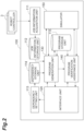
- FIG. 2 is a block diagram illustrating a configuration that is functionally equivalent to the programming assistance device 100.
- the programming assistance device 100 includes, as functional blocks, a job information storage unit 112, a job information acquisition unit 111, a dependency setting unit 113, a dependency storage unit 114, an interface unit 120, a program generation unit 130, a program storage unit 115, a program verification assistance unit 140, and a simulator 150.
- the job information storage unit 112 stores a plurality of work jobs for the robots 2.
- a work job is a program that is handled as one part of an operation program and includes at least one operating command.
- a work job may also include a plurality of operating commands arranged in chronological order.
- the jobs of the first program may include work jobs each of which defines a predetermined work motion of the first robot.
- the jobs of the second program may include work jobs each of which defines a predetermined work motion of the second robot.
- a work job is configured for each unit of work which the robots 2 are caused to execute.
- a unit of work include work completed in one continuous operation as in the case of welding along a single line.
- a unit of work may also include a plurality of discontinuous work as in the case of spot welding at a plurality of adjacent points.
- the execution time periods for individual operating commands vary according to the movement distance and movement speed.
- the execution time periods of a plurality of work jobs stored by the job information storage unit 112 are nonuniform.
- the work jobs are generated and stored by the robot controllers 3 of the robots 2 according to the work of teaching the robots 2 and the like.
- the job information acquisition unit 111 acquires the work jobs stored by each of the plurality of robot controllers 3 and registers, in the job information storage unit 112, work job identification information in association with the content of the work jobs.
- the interface unit 120 constitutes a so-called graphical user interface (GUI) to assist the generation of the operation program.
- GUI graphical user interface
- the interface unit 120 displays, on a display device, a user interface screen including a plurality of graphical elements and acquires operation information for selecting and moving the graphical elements, and so forth.
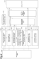
- FIG. 3 is a schematic diagram illustrating the user interface screen that is displayed by the interface unit 120.
- the user interface screen 200 displayed by the interface unit 120 includes a dependency input button 211, a flow creation button 212, a program creation button 213, a flow display window 220, a simulation window 240, and a timeline window 230.
- the dependency input button 211 is a button for starting dependency setting for each of a plurality of work jobs stored by the job information storage unit 112.
- the flow creation button 212 is a button for starting the creation of a flowchart determining the execution order of a plurality of work jobs.
- the program creation button 213 is a button for instructing the creation of the operation program according to the foregoing flowchart.
- the flow display window 220 is a window that displays a job image indicating, for each of the plurality of robots 2, a flowchart in which a plurality of jobs are arranged in execution order, and a marker indicating a part, in the flowchart, that is executed at the verification target time.
- the job image may comprise: a first flowchart in which a plurality of symbols corresponding to the jobs of the first program are arranged in execution order; a first marker indicating in the first flowchart the job program executed by the first robot at the verification target time; a second flowchart in which a plurality of symbols corresponding to the jobs of the second program are arranged in execution order; and a second marker indicating in the second flowchart the job program executed by the second robot at the verification target time.
- Each flowchart includes a plurality of work symbols each indicating a plurality of work jobs, and a plurality of movement symbols each indicating a plurality of transitional jobs.
- a plurality of symbols corresponding to the work jobs and the transitional job of the first program may be arranged in execution order in the first flowchart.
- the job image may include a first marker indicating in the first flowchart the job program executed by the first robot at the verification target time.
- a plurality of symbols corresponding to the work jobs and the transitional job of the second program may be arranged in execution order in the second flowchart.
- the job image may include a second marker indicating in the second flowchart the job program executed by the second robot at the verification target time.
- each flowchart includes a start point 221, a plurality of work blocks 222 (work symbols) each indicating a plurality of work jobs, a plurality of movement lines 223 (movement symbols) each indicating a plurality of transitional jobs, and an end point 224.
- the start point 221 indicates a work job (hereinbelow called “operation start job”) in which the tip part 12 is disposed in a predetermined operation start position and a predetermined operation start attitude.
- the end point 224 indicates a work job (hereinbelow called “operation end job”) in which the tip part 12 is disposed in a predetermined operation end position and a predetermined operation end attitude.
- the operation end position and operation end attitude may also be the same as the operation start position and operation start attitude.
- the plurality of work blocks 222 are arranged extending from the start point 221 toward the end point 224 in an arrangement order according to the execution order.
- the plurality of movement lines 223 include a movement line 223 that connects the start point 221 to an initial work block 222, a movement line 223 that connects together adjacent work blocks 222, and a movement line 223 that connects a final work block 222 to the end point 224. All the movement lines 223 indicate transitional jobs between two work jobs arranged in chronological order.
- the marker 225 is illustrated by means of an arrow shape next to the flowchart, for example, and indicates the part of the flowchart that is executed at the verification target time.
- the part that is executed at the verification target time may also be illustrated by using color, brightness, or thickness to highlight the display of the work block 222 or the movement line 223 executed at the verification target time.
- the work block 222 or movement line 223 itself whose display is highlighted functions as a marker.
- the simulation window 240 is a window that displays a simulation image of the plurality of robots 2 at the verification target time.
- the simulation image includes a robot image 241 that illustrates the robots 2 in their positions and attitude at the verification target time and a workpiece image 242 that illustrates workpieces in their positions and attitude at the verification target time.
- the simulation image may also further include an image illustrating objects neighboring the robots 2 such as jigs or conveyance devices.
- the timeline window 230 displays a time designation image for designating the verification target time.
- the time designation image may extend along a time elapse direction.
- the time designation image of the timeline window 230 includes an elapsed time bar 231 for each of the plurality of robots 2, a cursor 232, a playback button 233, a stop button 234, and a total time display unit 235.
- the elapsed time bar 231 is illustrated so as to follow the direction representing the time axis (the vertical direction in FIG. 3 ) and indicates the length of time by means of the length along this direction.
- the elapsed time bar 231 includes a work period display unit 236 indicating a work job execution period, a movement period display unit 237 indicating a transitional job execution period, and a standby period display unit 238 indicating a job execution standby period.
- the cursor 232 designates the verification target time by means of the position in the direction representing the time axis.
- the cursor 232 in FIG. 3 is illustrated in the form of a line crossing all the elapsed time bars 231 but is not limited thereto.
- the cursor 232 may be displayed in any way as long as the position in the direction representing the time axis is illustrated.
- the cursor 232 may be illustrated in the form of an arrow or a dot next to the elapsed time bar 231.
- the playback button 233 is a button for indicating the movement of the cursor 232 at a predetermined speed. As a result of moving the cursor 232, the marker 225 moves in the flow display window 220, and the robot images 241 and workpiece image 242 are displayed as moving images in the simulation window 240.
- the stop button 234 is a button for indicating stoppage of the movement of the cursor 232.
- the total time display unit 235 indicates the time required to execute the operation program.
- FIG. 3 two flowcharts are illustrated in the flow display window 220, two elapsed time bars 231 are illustrated in the timeline window 230, and two robot images 241 are illustrated in the simulation window 240, but the numbers of these images may be suitably changed according to the number of robots 2.
- the layout of the flow display window 220, timeline window 230, and simulation window 240 in FIG. 3 is merely an example and can be suitably changed.
- the flow display window 220 and simulation window 240 may also be displayed in an overlapping manner to enable switching by means of tab selection.
- the timeline window 230 may also be illustrated so that the time axis is horizontal.
- the dependency setting unit 113 displays, on the interface unit 120, an image for inputting dependency in response to the dependency input button 211 being pressed, and sets dependency between work jobs in response to inputs to the image.
- Dependency between work jobs signifies the execution timing relationship with another work job which should be satisfied in order to execute any given work job.
- the execution timing relationship includes, for example, a prior relationship between work jobs and an interval between the work jobs.
- the dependency setting unit 113 sets, for each work job, identification information of another work job to be executed beforehand (hereinafter called "required prior job"), and an interval to be provided after the required prior job. There may also be two or more required prior jobs.
- the dependency setting unit 113 displays, on the interface unit 120, a work job selection image (hereinafter called “target selection image”) in response to the dependency input button 211 being pressed. Additionally, the dependency setting unit 113 displays, on the interface unit 120, a dependency input image for a work job (hereinafter called “target job”) which is selected via the target selection image. Furthermore, the dependency setting unit 113 sets the dependency relating to the target job in response to an input to the dependency input image.
- the dependency input image is an image for inputting a required prior job and an interval to be provided after the required prior job, and may be configured to enable two or more required prior jobs to be designated.
- the dependency storage unit 114 stores dependency between work jobs that are preset by the dependency setting unit 113.
- the program generation unit 130 generates, for each of the plurality of robots 2, an operation program that includes a plurality of jobs based on information which the interface unit 120 acquires from the user interface screen 200.
- the program storage unit 115 stores, for each of the plurality of robots 2, the operation program generated by the program generation unit 130.
- the program storage unit 115 may be configured to store a first program and a second program.
- the first program comprises a first set of time series jobs. Each job of the first program defines at least one operation of the first robot.
- the first program is configured to be performed along a shared time line.
- the second program comprises a second set of time series jobs. Each job of the second program defines at least one operation of the second robot.
- the second program is configured to be performed along the shared time line.
- the first program may include at least two jobs execution periods of which are different from each other.
- the second program may include at least two jobs execution periods of which are different from each other.
- At least two of the first set of time series job include at least one command for the first robot indicating a target position and a target speed.
- At least two of the second set of time series jobs may include at least one command for the second robot indicating a target position and a target speed.
- the program verification assistance unit 140 executes, based on the operation program, the generation of a job image indicating jobs executed by the plurality of robots 2 at the verification target time and the generation of a simulation image of the plurality of robots 2 at the verification target time using the operation simulation based on the operation program.
- the program verification assistance unit 140 recognizes, based on the operation program stored by the program storage unit 115, jobs executed by the robots 2 at the verification target time and outputs the recognition results to the interface unit 120 to update the job image of the flow display window 220. Furthermore, the program verification assistance unit 140 generates a simulation image of the plurality of robots 2 at the verification target time using the operation simulation based on the operation program stored by the program storage unit 115 and outputs the simulation image to the interface unit 120 to update the simulation image of the simulation window 240.
- the simulator 150 executes the operation simulation.
- the simulator 150 holds model data indicating the arrangement, structure and part dimensions, and the like, of the robots 2 and uses an inverse kinematics operation to calculate the angles of the joints 31, 32, 33, 34, 35, and 36 according to the model data and the target position and target attitude of the tip part 12. Furthermore, based on the angles of the joints 31, 32, 33, 34, 35, and 36, the simulator 150 also determines the existence of collisions and generates the simulation image.
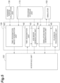
- the program generation unit 130 has, as functional blocks, an execution order setting unit 131, an executability checking unit 132, a generation condition setting unit 133, a generation condition storage unit 134, a transitional job generation unit 135, a standby period calculation unit 136, a generation condition change unit 137, and a revision location recognition unit 138.
- the execution order setting unit 131 sets, for each of the plurality of robots 2, the execution order of a plurality of work jobs based on inputs to the user interface screen 200.
- the execution order setting unit 131 may set a first execution order of the work jobs of the first program and a second execution order of the work jobs of the second program based on a user input.
- the execution order setting unit 131 displays, on the interface unit 120, a work job selection image (hereinafter called an "executed job selection image") in response to the flow creation button 212 being pressed.
- the executed job selection image is an image for inputting, for each of the robots 2, a plurality of work jobs to be executed (hereinafter called "executed jobs") and the execution order of the plurality of executed jobs.
- the execution order setting unit 131 sets, for each of the robots 2, the execution order of the plurality of executed jobs in response to inputs to the executed job selection image.
- the executability checking unit 132 checks whether the work motions of a robot 2 defined by the work jobs of the operation program satisfy a motion constraint (a sequential operating condition associated with at least two of the work jobs) of the robot 2.
- the executability checking unit 132 may check whether the execution order of the work jobs satisfies a sequential condition associated with at least two of the work jobs, based on the first program and the second program.
- the executability checking unit 132 determines, for each of the robots 2, the executability of a plurality of executed jobs according to the execution order (hereinafter called the "set order") set by the execution order setting unit 131, based on the motion constraint of each of the robots 2 and a dependency stored by the dependency storage unit 114 (a sequential condition associated with at least two of the work jobs).
- the motion constraint include a movable range of the tip part 12, a movable angle of the joints 31, 32, 33, 34, 35, and 36, or the like.
- the movable angle is the maximum operating angle permitted.
- the executability checking unit 132 causes the simulator 150 to calculate the operating angles of the joints 31, 32, 33, 34, 35, and 36 for moving the tip part 12 according to the executed job and acquires, from the simulator 150, the result of determining whether or not the calculation result lies within the movable angle. If it is determined by the simulator 150 that the operating angle of the joints 31, 32, 33, 34, 35, and 36 exceeds the movable angle, the executability checking unit 132 determines that the execution of the plurality of executed jobs according to the set order is impossible.
- the executability checking unit 132 also determines that the execution of the plurality of executed jobs according to the set order is impossible in cases where the required prior job for any executed job does not precede the executed job.
- the executability checking unit 132 may determine that the executed job satisfies dependency if the required prior job for any executed job is an executed job of another robot 2 of the robots 2 executing the executed job.
- the executability checking unit 132 saves, in the program storage unit 115 as the operation program, a program obtained by inserting the plurality of executed jobs between the operation start job and the operation end job according to the set order, for each of the plurality of robots 2. Accordingly, an operation program that moves the shortest distance between executed jobs is provisionally generated.
- the generation condition setting unit 133 sets, in the provisionally generated operation program, a transitional job generation condition as a preset initial condition, for each of the movement segments between work jobs (executed jobs).
- a transitional job generation condition include conditions for defining the number of jobs generated as transitional job candidates ("hereinafter called “candidate jobs") and a candidate job selection condition (hereinafter called the "first-type condition").
- the selection condition include the highest evaluation points for a movement job characteristic (movement time, movement distance, or power consumption during movement, or the like).
- the evaluation points may be points based on only one type of characteristic or may be points based on a plurality of types of characteristics.
- transitional job generation condition examples include a condition defining a threshold value for adopting evaluation points of a transitional job characteristic (hereinafter called a "second-type condition"). Furthermore, such conditions also include conditions defining the time or frequency for repeating candidate job generation and defining the candidate job selection condition (hereinafter called "third-type conditions"). Two or more of these types of generation conditions may also be combined.
- the generation condition storage unit 134 stores, for each of the movement segments, the generation conditions set by the generation condition setting unit 133.
- the transitional job generation unit 135 generates a transitional job so as to link between the endpoint of a preceding work job (the target position and target attitude of the final operating command) and the starting point of the following work job (the target position and target attitude of the initial operating command) and to avoid collisions of the robots 2 with workpieces and neighboring objects.
- the transitional job generation unit 135 generates a passing point that enables collision avoidance and repeats the revision of the transitional job to achieve passage via the passing point until collision avoidance is possible for the whole transitional job.
- the transitional job generation unit 135 When generating a transitional job, the transitional job generation unit 135 causes the simulator 150 to execute a determination of the existence of collisions of the robots 2 with workpieces and neighboring objects. Note that a method for generating a transitional job is also disclosed in detail in Japanese Patent No. 4103057 , for example.
- the transitional job generation unit 135 If the generation condition stored by the generation condition storage unit 134 is the first-type condition, the transitional job generation unit 135 generates, using the foregoing generation method, candidate jobs in a quantity defined by the first-type condition, and selects any candidate job as the transitional job according to the selection condition defined by the first-type condition.
- the transitional job generation unit 135 repeats the generation of candidate jobs until the time or frequency defined by the third-type condition is reached, and selects any candidate job as the transitional job according to the selection condition defined by the third-type condition.
- the standby period calculation unit 136 calculates (or sets), for each of the plurality of robots 2, the respective execution standby periods of the plurality of jobs (including the work jobs and transitional jobs) to adjust the relative operation timing of the plurality of robots 2.
- the standby period calculation unit 136 may calculate at least one standby period between two sequential jobs of the first program to adjust the relative operation timing of the first robot and the second robot.
- the standby period calculation unit 136 may calculate at least one standby period between two sequential jobs of the second program to adjust the relative operation timing of the first robot and the second robot.
- the time designation image may further include: a first time bar extending along the time elapse direction and including execution portions indicating execution periods of the first program and at least one standby portion indicating the at least one standby period of the first program; and a second time bar extending along the time elapse direction and including execution portions indicating execution periods of the second program and at least one standby portion indicating the at least one standby period of the second program.
- the execution portions of the first time bar may include work execution portions indicating execution periods of the work jobs of the first program and at least one transitional portion indicating an execution period of the at least one transitional job of the first program.
- the execution portions of the second time bar may include work execution portions indicating execution periods of the work jobs of the second program and at least one transitional portion indicating an execution period of the at least one transitional job of the second program. For example, if the operation program of another robot 2 includes a required prior job for a work job of any given robot 2, the standby period calculation unit 136 calculates the standby period of this work job so that the work job is started after the required prior job.
- the standby period calculation unit 136 calculates the job standby period of either of the robots 2 so that the jobs are executed sequentially.
- the standby period calculation unit 136 causes the simulator 150 to execute a determination of the existence of a collision between the robots 2.
- the programming assistance device 100 may be configured to revise the operation program based on an operating input to the flow display window 220.
- the execution order setting unit 131 may change the execution order of at least one robot 2 (hereinafter called the "revision target robot") pertaining to the movement of the work job in response to an input that moves the work job (for example, a dragging input that moves the work block 222) within the job image of the flow display window 220. If an input is made to move a work job between two flowcharts within the job image of the flow display window 220, there are two revision target robots.
- the execution order setting unit 131 may change the first execution order according to a user request to move a target job of the work jobs of the first program in the first flowchart.
- the execution order setting unit may change the first execution order and the second execution order according to a user request to move a target job of the work jobs between the first flowchart and the second flowchart.
- the executability checking unit 132 redetermines the executability of the plurality of executed jobs according to the changed execution order (hereinafter called the "changed order") for the revision target robots. Upon determining that the execution of the plurality of executed jobs according to the changed order is impossible, the executability checking unit 132 causes the interface unit 120 to display an error message that contains information indicating which condition of a particular executed job is not satisfied.
- the executability checking unit 132 uses the interface unit 120 to revise, according to the changed order, the flowcharts of the revision target robots in the flow display window 220.
- post-revision program a post-revision operation program (hereinafter called the "post-revision program") of the revision target robots is provisionally generated.
- the generation condition setting unit 133 changes, in the provisionally generated post-revision program, a transitional job generation condition as a preset initial condition, for each of the movement segments between work jobs, and saves the transitional job generation condition in the generation condition storage unit 134.
- the transitional job generation unit 135 regenerates at least one transitional job based on the execution order changed by the execution order setting unit 131. For example, the transitional job generation unit 135 regenerates, for each movement segment of the revised program, a transitional job according to generation conditions stored by the generation condition storage unit 134. The transitional job generation unit 135 regenerates at least one transitional job according to the first execution order changed according to the user request. The transitional job generation unit 135 regenerates at least one transitional job according to the second execution order changed according to the user request.
- the standby period calculation unit 136 changes, for each of the plurality of robots 2, the respective execution standby periods of the plurality of jobs based on the execution order recalculated (or changed) by the execution order setting unit 131 and the transitional job regenerated by the transitional job generation unit 135. In some examples, the standby period calculation unit 136 may recalculate the standby periods of the first program and the second program according to the changed first execution order.
- the program generation unit 130 may also further include the revision location recognition unit 138.
- the revision location recognition unit 138 recognizes a revision necessary location in which transitional job regeneration according to the change of the execution order by the execution order setting unit 131 is required and a revision unnecessary location in which transitional job regeneration is not required.
- the transitional job generation unit 135 regenerates a transitional job of the revision necessary location without regenerating the transitional job of the revision unnecessary location.
- the transitional job generation unit 135 may skip regeneration of a transitional job which is not associated with the work job moved by the user.
- the revision location recognition unit 138 may identify one or more pairs of sequential work jobs which include a transitional job of the at least one transitional job therebetween, according to the first execution order.
- the revision location recognition unit 138 may identify a pair of sequential work jobs in the one or more pairs of sequential work jobs, which does not include the target job therebetween, according to the first execution order changed according to the user request.
- the transitional job generation unit 135 may retain the transitional job between the pair of sequential work jobs which does not include the target job therebetween in the first execution order changed according to the user request.
- the revision location recognition unit 138 confirms whether or not the same movement segment exists in the pre-revision operation program (hereinafter called the "pre-revision program") for each of the movement segments of the post-revision program.
- the same movement segment signifies a movement segment for which there is coincidence between the preceding and subsequent work jobs. If a movement segment which is the same as the movement segment of the post-revision program does not exist in the pre-revision program, the revision location recognition unit 138 recognizes this movement segment as a revision necessary location.
- the revision location recognition unit 138 recognizes this movement segment as a revision unnecessary location and inserts the same transitional job as in the pre-revision program into the movement segment.
- the transitional job generation unit 135 does not regenerate, in the post-revision program, the transitional job of the movement segment into which the transitional job has been inserted and regenerates a transitional job of a movement segment into which a transitional job has not been inserted.
- the program generation unit 130 may further include the generation condition change unit 137.
- the generation condition change unit 137 individually changes the generation conditions of transitional jobs in response to inputs to a job image in the flow display window 220.
- the generation condition change unit may select a transitional job pointed by a user in the job image; and change a generation condition for the selected transitional job according to an input by the user.
- the generation condition change unit 137 causes the interface unit 120 to display a generation condition input image for a transitional job in response to an input (for example, clicking of the movement line 223) to select the transitional job in the job image in the flow display window 220 and changes the generation condition of the transitional job based on the input to the input image.
- the generation condition change unit 137 sets the generation condition of the transitional job based on the input to the input image and overwrites the generation condition storage unit 134.
- the transitional job generation unit 135 regenerates, based on the generation condition changed by the generation condition change unit 137, a transitional job that corresponds to the changed generation condition.
- the generation condition change unit 137 erases the transitional job from the program storage unit 115.
- the transitional job generation unit 135 regenerates the transitional job of the movement segment from which the transitional job has been erased.
- the program verification assistance unit 140 includes, as functional blocks, a time designation image generation unit 141, a time designation unit 142, a job image generation unit 143, a simulation image generation unit 144, and a playback processing unit 145.
- the time designation image generation unit 141 generates a time designation image that includes a cursor indicating the position in a direction representing the time axis.
- the time designation image generation unit 141 also generates a time designation image that further includes, for each of the plurality of robots 2, an elapsed time bar indicating, along the time axis, a job execution period and a job execution standby period.
- the time designation image generation unit 141 changes position of the time cursor in the time elapse direction based on an user input to the time designation image.
- the time designation image generation unit 141 may also generate a time designation image to further indicate, on the elapsed time bar, an execution period of the work job and an execution period of the transitional job.
- the time designation image generation unit 141 generates the data of the time designation image in the timeline window 230 described above and causes the interface unit 120 to display, in the timeline window 230, the time designation image according to the data.
- a graphical user interface that includes the time designation image is thus constituted.
- the time designation image generation unit 141 may also be configured to update the elapsed time bar 231 based on the execution order changed by the execution order setting unit 131, the transitional job regenerated by the transitional job generation unit 135, and the execution standby period changed by the standby period calculation unit 136. In some examples, time designation image generation unit 141 may update the first time bar and the second time bar based on the changed first execution order, the regenerated transitional job, and the recalculated standby periods.
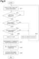
- FIG. 9 illustrates a procedure executed by the programming assistance device 100 if the flow creation button 212 of the user interface screen 200 is pressed.
- the programming assistance device 100 first executes steps S11, S12, and S13.
- the execution order setting unit 131 causes the interface unit 120 to display the work job selection image (the foregoing executed job selection image).
- the execution order setting unit 131 awaits the issuance of a flowchart creation request (waits for the execution button to be pressed, for example) via the executed job selection image.
- step S13 the executability checking unit 132 determines, for each of the robots 2, whether execution of a plurality of executed jobs is possible according to the execution order (the set order) set by the execution order setting unit 131, based on motion constraint of each of the plurality of robots 2.
- the executability checking unit 132 causes the simulator 150 to calculate the operating angles of the joints 31, 32, 33, 34, 35, and 36 for moving the tip part 12 according to the executed job and acquires, from the simulator 150, the result of determining whether or not the calculation result lies within the movable angle.
- step S13 If it is determined in step S13 that the calculation result lies within the movable angle, the programming assistance device 100 executes step S14.
- step S14 the executability checking unit 132 confirms whether there is an executed job not satisfying the dependency
- step S15 the executability checking unit 132 causes the interface unit 120 to display an error message containing information indicating which of the conditions in a particular executed job are not satisfied. Thereafter, the programming assistance device 100 returns the processing to step S11. Accordingly, the selection of a work job is requested once again.
- step S16 the executability checking unit 132 uses the interface unit 120 to display, in the flow display window 220 and according to the set order, a flowchart for each of the plurality of robots 2.
- step S17 the executability checking unit 132 provisionally generates, as an operation program, a program obtained by inserting the plurality of executed jobs between the operation start job and the operation end job according to the set order, for each of the plurality of robots 2, and saves the provisionally generated operation program in the program storage unit 115.
- step S18 the generation condition setting unit 133 sets, in the provisionally generated operation program, a transitional job generation condition as a preset initial condition, for each of the movement segments between work jobs.
- step S19 the interface unit 120 activates the program creation button 213. Note that activation signifies an enabling operation by a user.
- the execution order setting procedure is completed as outlined hereinabove.
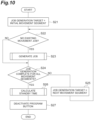
- FIG. 10 illustrates a procedure executed for each of the robots 2 by the programming assistance device 100 if the activated program creation button 213 is pressed.
- the programming assistance device 100 first executes steps S21 and S22.
- step S21 the transitional job generation unit 135 sets, for an initial movement segment of the operation program in the program storage unit 115, a transitional job generation target.
- a movement segment of a transitional job generation target is called a "target segment" hereinbelow.
- the transitional job generation unit 135 confirms whether or not there is an existing transitional job in the target segment.
- step S23 the transitional job generation unit 135 generates a transitional job of the target segment according to the generation condition stored by the generation condition storage unit 134. The specific content of step S23 will subsequently be described.
- step S24 The programming assistance device 100 then executes step S24. If it is determined in step S22 that there is an existing transitional job in the target segment, the programming assistance device 100 executes step S24 without executing step S23. In step S24, the transitional job generation unit 135 confirms whether or not a transitional job exists in all the movement segments.
- step S24 If it is determined in step S24 that there is a movement segment without a transitional job, the programming assistance device 100 executes step S25.
- step S25 the transitional job generation unit 135 changes the target segment to the next movement segment. Thereafter, the programming assistance device 100 returns the processing to step S22. Subsequently, until it is determined that a transitional job exists in all the movement segments, the programming assistance device 100 generates and repeats the insertion of a transitional job into a movement segment in which a transitional job has not been inserted.
- step S26 the standby period calculation unit 136 calculates, for each of the plurality of robots 2, the respective execution standby periods of the plurality of jobs (including the work jobs and transitional jobs) to adjust the relative operation timing of the plurality of robots 2.
- step S27 the interface unit 120 deactivates the program creation button 213. Note that deactivation signifies a prohibiting operation by a user.
- the operation program generation procedure is completed as outlined hereinabove.
- FIG. 11 is a flowchart illustrating the transitional job generation procedure in step S23.
- FIG. 11 illustrates a transitional job generation procedure based on the foregoing first-type generation condition.
- the programming assistance device 100 first executes steps S31 and S32.
- step S31 the transitional job generation unit 135 provisionally generates a transitional job to create the shortest route between the work jobs.
- step S32 the transitional job generation unit 135 confirms whether or not there is a collision, for the whole transitional job, between the robots 2 and the workpieces and neighboring objects.
- step S32 If it is determined in step S32 that there is a collision between the robots 2 and the workpieces and neighboring objects, the programming assistance device 100 executes steps S33 and S34.
- step S33 the transitional job generation unit 135 generates passing points enabling collision avoidance.
- step S34 the transitional job generation unit 135 revises the transitional job for passage through the generated passing points. Thereafter, the programming assistance device 100 returns the processing to step S32. Subsequently, until it is determined that there is no collision, for the whole transitional job, between the robots 2 and the workpieces and neighboring objects, the addition of passing points and transitional job revision are repeated.
- step S35 the transitional job generation unit 135 takes the transitional jobs generated thus far as candidate jobs.
- step S36 the transitional job generation unit 135 confirms whether or not the number of candidate jobs has reached the number (hereinafter called the "predefined number") defined by the first-type condition.
- step S36 If it is determined in step S36 that the number of candidate jobs has not reached the predefined number, the programming assistance device 100 returns the processing to step S31. Subsequently, until the number of candidate jobs reaches the predefined number, the generation of candidate jobs is repeated. If it is determined in step S36 that the number of candidate jobs has reached the predefined number, the programming assistance device 100 executes step S37.
- step S37 the transitional job generation unit 135 selects any candidate job as a transitional job according to the selection condition defined by the first-type condition. The transitional job generation procedure is completed as outlined hereinabove.
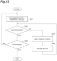
- FIG. 12 illustrates a transitional job generation procedure based on the foregoing second-type generation condition. As illustrated in FIG. 12 , until it is determined that there is no collision, for the whole transitional job, between the robots 2 and the workpieces and neighboring objects, the programming assistance device 100 first repeats steps S41, S42, S43, and S44 which are like steps S31, S32, S33, and S34.
- step S42 If it is determined in step S42 that there is no collision, for the whole transitional job, between the robots 2 and the workpieces and neighboring objects, the programming assistance device 100 executes step S45.
- step S45 the transitional job generation unit 135 confirms whether or not the characteristic of the transitional job has exceeded the adoption threshold value defined by the second-type condition.
- step S45 If it is determined in step S45 that the characteristic of the transitional job has not exceeded the adoption threshold value defined by the second-type condition, the programming assistance device 100 returns the processing to step S41. Subsequently, until a transitional job exceeding the adoption threshold value is generated, the generation of transitional jobs is repeated. If it is determined in step S45 that the characteristic of the transitional job has exceeded the adoption threshold value defined by the second-type condition, the transitional job generation procedure is complete.
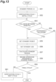
- FIG. 13 illustrates the standby period calculation procedure of step S26.
- the programming assistance device 100 first executes steps S51, S52, and S53.
- step S51 the standby period calculation unit 136 sets the standby period of each job at zero.
- step S52 the standby period calculation unit 136 sets a standby requirement/non-requirement verification cycle at an initial control cycle.
- a control cycle is one cycle of control in which feedback and a deviation-based instruction output are periodically repeated.
- step S53 the standby period calculation unit 136 confirms whether there are collisions between the robots 2 in the verification cycle.
- the standby period calculation unit 136 outputs, to the simulator 150, the target position and target attitude of the tip part 12 of each robot 2 in the verification cycle and causes the simulator 150 to determine the existence of collisions between the robots 2.
- step S53 If it is determined in step S53 that there are no collisions between the robots 2 in the verification cycle, the programming assistance device 100 executes step S54.
- step S54 the standby period calculation unit 136 confirms whether or not there is a work job started before completion of the required prior job.
- step S53 If it is determined in step S53 that there is a collision between the robots 2 in the verification cycle or if it is determined in step S54 that there is a work job started before completion of the required prior job, the programming assistance device 100 executes steps S55, S56, S57, and S58.
- step S55 the standby period calculation unit 136 selects a robot 2 whose operation is placed on standby (hereinafter called the "standby robot"). For example, if a collision between the robots 2 is detected, the standby period calculation unit 136 takes either one of the robots 2 as the standby robot. Furthermore, if a work job started before completion of the required prior job is detected, the standby period calculation unit 136 takes the robot 2 executing this work job as the standby robot.
- step S56 the standby period calculation unit 136 sets the job executed in the verification cycle by the selected robot 2 as a standby job.
- step S57 the standby period calculation unit 136 sets the standby period of the selected standby job.
- the standby period calculation unit 136 uses, as the standby period, a period until completion of a job executed in the verification cycle by the other robot 2 implicated in the collision, for example.
- the standby period calculation unit 136 uses, as the standby period, the period until the other robot 2 completes the required prior job.
- the standby period calculation unit 136 uses, as the standby period, the period until the interval has elapsed after the other robot 2 completes the required prior job.
- the standby period calculation unit 136 revises the operation program of the standby robot by inserting the standby period set in step S57 before the standby job set in step S56.
- step S59 The programming assistance device 100 then executes step S59. If it is determined in step S54 that there is no work job started before completion of the required prior job, the programming assistance device 100 executes step S59 without executing steps S55, S56, S57, and S58. In step S59, the standby period calculation unit 136 confirms whether the verification cycle is the final control cycle.
- step S59 If it is determined in step S59 that the verification cycle is not the final control cycle, the programming assistance device 100 executes step S61.
- step S61 the standby period calculation unit 136 changes the verification cycle to the next control cycle. Thereafter, the programming assistance device 100 returns the processing to step S53. Subsequently, until the verification of the final control cycle is complete, the determination of the requirement/non-requirement of the standby period and the calculation of the standby period where necessary are repeated. If it is determined in step S59 that the verification cycle is the final control cycle, the standby period calculation procedure is complete.
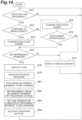
- FIG. 14 illustrates an execution order change procedure in response to an input via the flow display window 220.
- the programming assistance device 100 first executes steps S71 and S72.
- step S71 the interface unit 120 awaits an input to move the work block 222 (that is, the foregoing input to move the executed job) within the flow display window 220.
- step S72 the execution order setting unit 131 confirms whether or not the movement of the executed job is movement confined to a single robot 2.
- step S72 If it is determined in step S72 that the executed job movement is movement confined to a single robot 2, the programming assistance device 100 executes steps S73 and S74.
- step S73 the execution order setting unit 131 changes the execution order of a single robot 2 (the foregoing revision target robot) relating to movement of the executed job in response to an input to move the executed job.
- step S74 the executability checking unit 132 confirms whether there is an executed job not satisfying dependency.
- step S72 If it is determined in step S72 that the executed job movement is not movement confined to a single robot 2, the programming assistance device 100 executes steps S75 and S76.
- step S75 the execution order setting unit 131 changes the execution order of two robots 2 (the foregoing revision target robots) pertaining to the movement of the executed job in response to an input to move the executed job.
- step S76 the executability checking unit 132 determines, for each of the two revision target robots, whether execution of a plurality of executed jobs is possible according to the execution order (the changed order) changed by the execution order setting unit 131, based on the motion constraint of each of the two revision target robots.
- the executability checking unit 132 causes the simulator 150 to calculate the operating angles of the joints 31, 32, 33, 34, 35, and 36 for moving the tip part 12 according to the executed job and acquires, from the simulator 150, the result of determining whether or not the calculation result lies within the movable angle.
- step S76 If it is determined in step S76 that the execution of the plurality of executed jobs is possible according to the changed order, the programming assistance device 100 advances the processing to step S74.
- step S74 If it is determined in step S74 that there is an executed job not satisfying dependency or it is determined in step S76 that execution of the plurality of executed jobs according to the changed order is not possible, the programming assistance device 100 executes step S77.
- step S77 the executability checking unit 132 causes the interface unit 120 to display an error message containing information indicating which of the conditions in a particular executed job does not satisfy. Thereafter, the programming assistance device 100 returns the processing to step S71.
- step S74 If it is determined in step S74 that there is no executed job not satisfying dependency, the programming assistance device 100 executes steps S78, S79, S81, S82, S83, and S84.
- step S78 the executability checking unit 132 uses the interface unit 120 to display, in the flow display window 220 and according to the changed order, a flowchart for each of the revision target robots.
- step S79 the executability checking unit 132 saves, in the program storage unit 115 as the operation program of the revision target robots, a program obtained by inserting the plurality of executed jobs between the operation start job and the operation end job according to the changed order. Accordingly, a post-revision operation program (the "post-revision program") of the revision target robots is provisionally generated.
- the revision location recognition unit 138 recognizes a revision necessary location in which transitional job regeneration according to the change of the execution order by the execution order setting unit 131 is required and a revision unnecessary location in which transitional job regeneration is not required. For example, the revision location recognition unit 138 confirms whether or not the same movement segment exists in the pre-revision program for each of the movement segments of the post-revision program. If a movement segment which is the same as the movement segment of the post-revision program does not exist in the pre-revision program, the revision location recognition unit 138 recognizes this movement segment as a revision necessary location. If a movement segment which is the same as the movement segment of the post-revision program exists in the pre-revision program, the revision location recognition unit 138 recognizes this movement segment as a revision unnecessary location.
- step S82 the revision location recognition unit 138 inserts the same transitional job as in the pre-revision program into the movement segment recognized as a revision unnecessary location.
- step S83 the generation condition setting unit 133 changes the transitional job generation condition as a preset initial condition, for each of the movement segments recognized as revision necessary locations by the revision location recognition unit 138, and saves the transitional job generation condition in the generation condition storage unit 134.
- step S84 the interface unit 120 activates the program creation button 213. Thereafter, the programming assistance device 100 returns the processing to step S71.
- the programming assistance device 100 executes the foregoing program generation procedure once again.
- the transitional job generation unit 135 regenerates a transitional job of a movement segment where a transitional job does not exist without regenerating a transitional job of a movement segment where a transitional job exists.
- a transitional job of a revision necessary location is regenerated without a transitional job of a revision unnecessary location being regenerated.
- FIG. 15 illustrates a generation condition change procedure in response to an input via the flow display window 220.
- the programming assistance device 100 executes steps S91, S92, S93, S94, S95, and S96.
- step S91 for example, the generation condition change unit 137 waits for an input to be made (for example, clicking of the movement line 223) to select a transitional job in an upper image of the flow display window 220.
- step S92 the generation condition change unit 137 causes the interface unit 120 to display a generation condition input image for the selected transitional job.
- step S93 the generation condition change unit 137 awaits the issuance of a generation condition registration request (waits for the registration button to be pressed, for example) via the generation condition input image.
- step S94 the generation condition change unit 137 changes the generation condition of the transitional job based on an input to the generation condition input image. For example, the generation condition change unit 137 sets the generation condition of the transitional job based on the input to the generation condition input image and overwrites the generation condition storage unit 134.
- step S95 the generation condition change unit 137 erases, from the program storage unit 115, the transitional job whose generation condition has been changed.
- step S96 the interface unit 120 activates the program creation button 213. Thereafter, the programming assistance device 100 returns the processing to step S91.
- the programming assistance device 100 executes the foregoing program generation procedure once again.
- the transitional job generation unit 135 regenerates a transitional job of a movement segment where a transitional job does not exist without regenerating a transitional job of a movement segment where a transitional job exists.
- the transitional job is regenerated based on the changed generation condition.
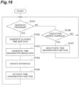
- FIG. 16 illustrates a time designation image display procedure according to the generation and revision of the operation program.
- the programming assistance device 100 first executes step S101.
- step S101 the time designation image generation unit 141 confirms whether a new operation program has been generated in the program storage unit 115.
- step S101 If it is determined in step S101 that a new operation program has been generated in the program storage unit 115, the programming assistance device 100 executes steps S102, S103, S104, and S105.
- step S102 the time designation image generation unit 141 generates, for each of the plurality of robots 2, display data of the elapsed time bar 231 based on the execution order set by the execution order setting unit 131, the transitional job generated by the transitional job generation unit 135, and the execution standby period calculated by the standby period calculation unit 136.
- step S103 the time designation image generation unit 141 generates the data of the time designation image in the timeline window 230 based on the display data of the elapsed time bar 231.
- step S104 the time designation image generation unit 141 uses the interface unit 120 to display, in the timeline window 230, the time designation image according to the generated data.
- step S105 the interface unit 120 activates the timeline window 230.
- verification time designation through movement of the cursor 232 and operation of the playback button 233 and stop button 234 are enabled. Thereafter, the programming assistance device 100 returns the processing to step S101.
- step S101 If it is determined in step S101 that a new operation program has not been generated in the program storage unit 115, the programming assistance device 100 executes step S106.
- step S106 the interface unit 120 confirms whether or not the execution order has been changed by the execution order setting unit 131. If it is determined in step S106 that the execution order has not been changed, the programming assistance device 100 returns the processing to step S101.
- step S107 the interface unit 120 deactivates the timeline window 230. Thus, verification time designation through movement of the cursor 232 and operation of the playback button 233 and stop button 234 are prohibited. Thereafter, the programming assistance device 100 returns the processing to step S101.
- the time designation image generation unit 141 updates the elapsed time bar 231 based on the execution order changed by the execution order setting unit 131, the transitional job regenerated by the transitional job generation unit 135, and the execution standby period changed by the standby period calculation unit 136 (steps S102, S103, S104). Furthermore, the interface unit 120 re-activates the timeline window 230 (step S105). As described hereinabove, updating of the time designation image in accordance with revision of the operation program is continued.
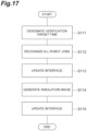
- FIG. 17 illustrates a procedure for displaying a job image and a simulation image in response to an input to move the cursor 232.
- the programming assistance device 100 executes steps Sill, S112, S113, S114, and S115.
- the time designation unit 142 designates the verification target time according to the position of the cursor on the time designation image.
- the job image generation unit 143 recognizes, based on the operation program stored by the program storage unit 115, a job executed by a plurality of robots 2 at the verification target time.
- the job image generation unit 143 uses the interface unit 120 to display, in the flow display window 220, a marker 225 indicating the recognized job.
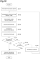
- FIG. 18 illustrates a procedure for moving-image playback of a job image and a simulation image when the playback button 233 is pressed.
- the programming assistance device 100 first executes steps S121, S122, S123, S124, S125, S126, and S127.
- step S121 the interface unit 120 prohibits movement, in the flow display window 220, of the work block 222, and changing of the generation condition thereof.
- step S122 the time designation unit 142 designates the verification target time according to the position of the cursor on the time designation image.
- the job image generation unit 143 recognizes, based on the operation program stored by the program storage unit 115, jobs executed by a plurality of robots 2 at the verification target time.
- the job image generation unit 143 uses the interface unit 120 to display, in the flow display window 220, markers 225 indicating the recognized jobs.
- step S127 If it is determined in step S127 that the cursor 232 has not reached the end of the elapsed time bar 231, the programming assistance device 100 executes step S128.
- step S129 the playback processing unit 145 advances the cursor 232 by one (advances the cursor 232 in the direction of elapsed time) at a predetermined pitch. Thereafter, the programming assistance device 100 returns the processing to step S122. Subsequently, until the cursor 232 reaches the end or the stop button 234 is pressed, advancement of the cursor 232 and the updating of the job image and simulation image are repeated.
- step S131 the interface unit 120 cancels the prohibition on movement, in the flow display window 220, of the work block 222, and the prohibition on changing the generation condition thereof.
- the moving image playback procedure is completed as outlined hereinabove.
- the programming assistance device 100 comprises a program storage unit 115 configured to store, for each of a plurality of robots, an operation program that includes a plurality of jobs; and a job image generation unit 143 which, if a verification target time is designated by a user, is configured to generate, based on the operation program, a job image indicating jobs executed by a plurality of robots 2 at the verification target time.
- the execution time of the plurality of jobs may not be fixed and the plurality of jobs may include at least two jobs having execution periods which are different from each other.
- each job performed by a robot may comprise a plurality of operating commands arranged in chronological order.
- the operating command may designate a target position and a movement speed.
- the time that it takes the robot to complete the operating command may be a function of the distance to the target position from the current position of the robot, and the movement speed. Accordingly, when a first robot and a second robot each perform different jobs, the jobs may be completed at different times even if the jobs have the same number of commands.
- the programming assistance device 100 may be configured to generate a job display image indicating the jobs executed by the plurality of robots 2 at the designated verification target time.
- the programming assistance device 100 may further comprise a simulation image generation unit 144 configured to generate a simulation image of a plurality of robots 2 at the verification target time by performing an operation simulation based on an operation program; and an interface unit 120 configured to generate a user interface that includes a job image and the simulation image.
- a simulation image generation unit 144 configured to generate a simulation image of a plurality of robots 2 at the verification target time by performing an operation simulation based on an operation program
- an interface unit 120 configured to generate a user interface that includes a job image and the simulation image.
- the user is also able to readily ascertain the relationship between the robots 2 by adding the simulation image at the verification target time. Therefore, the operation programming of the plurality of robots 2 is more effectively optimized.
- the job image generation unit 143 may also generate a job image so as to indicate, for each of the plurality of robots 2, a flowchart in which a plurality of jobs are arranged in execution order, and a marker 225 indicating a part, in the flowchart, that is executed at the verification target time.
- the jobs at the verification target time are displayed together with preceding and subsequent jobs. It is thus easy to visually ascertain editing locations which are effective for fine-tuning the operation program. Therefore, the operation programming of the plurality of robots 2 is more effectively optimized.
- the programming assistance device 100 may further comprise an execution order setting unit 131 configured to set, for each of a plurality of robots 2, an execution order of a plurality of work jobs; and a transitional job generation unit 135 configured to generate, for the plurality of robots, a transitional job between the plurality of work jobs based on the execution order set by the execution order setting unit 131, wherein the job image generation unit 143 may generate a job image indicating, for each of the plurality of robots 2, a flowchart that includes a plurality of work blocks 222 indicating the plurality of work jobs respectively and movement lines 223 indicating the transitional jobs. In this case, it is easier to visually ascertain editing locations which are effective for fine-tuning the operation program. Therefore, the operation programming of the plurality of robots 2 is more effectively optimized.
- the programming assistance device 100 may further comprise a time designation image generation unit 141 configured to generate a time designation image that includes a cursor 232 indicating a position in a direction representing a time axis and a time designation unit 142 configured to designate the verification target time according to the position of the cursor 232 in the time designation image, wherein the interface unit 120 may generate a user interface that further includes the time designation image.
- the verification target time can be easily designated. Therefore, the operation programming of the plurality of robots 2 is more effectively optimized.
- the programming assistance device 100 may further comprise a standby period calculation unit 136 configured to calculate, for each of a plurality of robots 2, the respective execution standby periods of a plurality of jobs to adjust the relative operation timing of the plurality of robots 2, wherein the time designation image generation unit 141 may generate a time designation image that further includes, for each of the plurality of robots 2, an elapsed time bar 231 indicating, along a time axis, a job execution period and a job execution standby period.
- a standby period calculation unit 136 configured to calculate, for each of a plurality of robots 2, the respective execution standby periods of a plurality of jobs to adjust the relative operation timing of the plurality of robots 2, wherein the time designation image generation unit 141 may generate a time designation image that further includes, for each of the plurality of robots 2, an elapsed time bar 231 indicating, along a time axis, a job execution period and a job execution standby period.
- a time designation image that further includes, for each of the plurality of robots 2, an elapsed time bar 231 indicating, along a time axis, a job execution period and a job execution standby period, is displayed.
- the positions to serve as verification target times can be easily filtered and the filtered positions can be more easily designated from the disposition of the cursor 232. Therefore, the operation programming of the plurality of robots 2 is more effectively optimized.
- the time designation image generation unit 141 may also generate a time designation image to further indicate, on the elapsed time bar 231, an execution period of the work job and an execution period of the transitional job. In this case, filtering of the positions to be designated as a verification target time is more straightforward.
- the programming assistance device 100 may further comprise a generation condition change unit 137 configured to individually change the transitional job generation condition in response to an input to the job image, wherein the transitional job generation unit 135 may regenerate, based on the changed generation condition, the transitional job corresponding to the generation condition changed by the generation condition change unit 137.
- a generation condition change unit 137 configured to individually change the transitional job generation condition in response to an input to the job image, wherein the transitional job generation unit 135 may regenerate, based on the changed generation condition, the transitional job corresponding to the generation condition changed by the generation condition change unit 137.
- the execution order setting unit 131 may change the execution order of at least one robot 2 in response to the input for moving the work job in the job image, and the transitional job generation unit 135 may also regenerate at least one transitional job according to the execution order changed by the execution order setting unit.
- the execution order change and transitional job regeneration can be performed by means of a simple operation of moving the work jobs in the job image. Hence, editing and verification of the operation program can be efficiently repeated. Therefore, the operation programming of the plurality of robots 2 is more effectively optimized.
- the execution order setting unit 131 may change the execution order of two robots 2 pertaining to the movement of the work job in response to an input for moving the work job between two flowcharts in the job image, and the transitional job generation unit 135 may regenerate, for the two robots 2, at least one transitional job according to the execution order changed by the execution order setting unit 131.
- the allocation of work jobs to the plurality of robots 2 can be changed and the execution order change and transitional job regeneration can be performed accordingly. Therefore, the operation programming of the plurality of robots 2 is more effectively optimized.
- the programming assistance device 100 may further comprise a revision location recognition unit 138 configured to recognize a revision necessary location in which transitional job regeneration according to the change of the execution order by the execution order setting unit 131 is required and a revision unnecessary location in which transitional job regeneration is not required, wherein the transitional job generation unit 135 may regenerate a transitional job of a revision necessary location without regenerating a transitional job of a revision unnecessary location.
- the processing burden of the transitional job regeneration can be alleviated. Therefore, the operation programming of the plurality of robots 2 is more effectively optimized.
- the execution order setting unit 131 may change the execution order of at least one robot 2 in response to the input for moving the work job in the job image, and the transitional job generation unit 135 may regenerate at least one transitional job according to the execution order changed by the execution order setting unit 131. Additionally, the standby period calculation unit 136 may change, for each of the plurality of robots 2, the respective execution standby periods of the plurality of jobs based on the execution order changed by the execution order setting unit 131 and the transitional job regenerated by the transitional job generation unit 135.
- time designation image generation unit 141 may update the elapsed time bar 231 based on the execution order changed by the execution order setting unit 131, the transitional job regenerated by the transitional job generation unit 135, and the execution standby period changed by the standby period calculation unit 136. In this case, editing and verification of the operation program can be more efficiently repeated. Therefore, the operation programming of the plurality of robots 2 is more effectively optimized.
- the programming assistance device 100 may further comprise an executability checking unit 132 configured to determine executability of work jobs based on the motion constraint of each of the plurality of robots 2. In this case, futile editing inputs are suppressed. Therefore, the operation programming of the plurality of robots 2 is more effectively optimized.
- the programming assistance device 100 may further comprise the dependency storage unit 114 configured to store dependency between preset work jobs, wherein the executability checking unit 132 may determine the executability of the work jobs also based on dependency. In this case, futile editing inputs are suppressed. Therefore, the operation programming of the plurality of robots 2 is more effectively optimized.
Landscapes
- Engineering & Computer Science (AREA)
- Robotics (AREA)
- Mechanical Engineering (AREA)
- Physics & Mathematics (AREA)
- General Physics & Mathematics (AREA)
- Automation & Control Theory (AREA)
- General Engineering & Computer Science (AREA)
- Manipulator (AREA)
- Numerical Control (AREA)
Claims (15)
- Eine Programmierassistenzvorrichtung (100), umfassend:
eine Programmspeichereinheit (115), die konfiguriert ist, um:erste Arbeitsaufträge zu speichern, die in einer ersten Ausführungsreihenfolge auszuführen sind, wobei jeder der ersten Arbeitsaufträge mindestens einen Befehl enthält, der eine Zielposition und eine Zielgeschwindigkeit für einen ersten Roboter (2) angibt, wobei die ersten Arbeitsaufträge eine oder mehrere vorbestimmte Arbeitsbewegungen eines ersten Programms definieren, die entlang einer gemeinsamen Zeitlinie auszuführen sind; undSpeichern von zweiten Arbeitsaufträgen, die in einer zweiten Ausführungsreihenfolge auszuführen sind, wobei jeder der zweiten Arbeitsaufträge mindestens einen Befehl enthält, der eine Zielposition und eine Zielgeschwindigkeit für einen zweiten Roboter (2) angibt, wobei die zweiten Arbeitsaufträge eine oder mehrere vorbestimmte Arbeitsbewegungen eines zweiten Programms definieren, das entlang der gemeinsamen Zeitlinie auszuführen ist; undeine Übergangsjob-Erzeugungseinheit (135), die konfiguriert ist, um:Erzeugen eines oder mehrerer erster Übergangsjobs, die eine Bewegung des ersten Roboters (2) zwischen einem oder mehreren Paaren von aufeinanderfolgenden ersten Arbeitsaufträgen der ersten Arbeitsaufträge definieren, um Kollisionen des ersten Roboters (2) zu vermeiden, indem eine Betriebssimulation des ersten Roboters (2) basierend auf dem einen oder den mehreren ersten Übergangsjobs durchgeführt wird; undErzeugen eines oder mehrerer zweiter Übergangsjobs, die eine Bewegung des zweiten Roboters (2) zwischen einem oder mehreren Paaren von aufeinanderfolgenden zweiten Arbeitsaufträgen der zweiten Arbeitsaufträge definieren, um Kollisionen des zweiten Roboters (2) zu vermeiden, indem eine Betriebssimulation des zweiten Roboters (2) auf der Grundlage des einen oder der mehreren zweiten Übergangsjobs durchgeführt wird;eine Zeitbestimmungseinheit (142), die so konfiguriert ist, dass sie eine Verifizierungszielzeit in der gemeinsamen Zeitlinie zumindest teilweise auf der Grundlage einer Benutzerbestimmung bestimmt;eine Simulationsbilderzeugungseinheit (144), die so konfiguriert ist, dass sie ein Simulationsbild des ersten Roboters (2) und des zweiten Roboters (2) zu der Verifizierungszielzeit erzeugt, indem sie eine Betriebssimulation auf der Grundlage des ersten Programms und des zweiten Programms durchführt; undeine Jobbild-Erzeugungseinheit (143), die konfiguriert ist, umauf der Grundlage des ersten Programms und des zweiten Programms ein Auftragsbild zu erzeugen, das mindestens einen Auftrag des ersten Programms, der dem Simulationsbild entspricht, zur Verifizierungszielzeit anzeigt, und mindestens einen Auftrag des zweiten Programms, der dem Simulationsbild zur Verifizierungszielzeit entspricht; undeine Ausführungsreihenfolge-Einstelleinheit (131), die so konfiguriert ist, dass sie mindestens eine Ausführungsreihenfolge der ersten Ausführungsreihenfolge und der zweiten Ausführungsreihenfolge gemäß einer Benutzeranforderung ändert,wobei die Übergangsjob-Erzeugungseinheit (135) ferner so konfiguriert ist, dass sie mindestens einen Übergangsjob des einen oder der mehreren ersten Übergangsjobs und des einen oder der mehreren zweiten Übergangsjobs auf der Grundlage der mindestens einen geänderten Ausführungsreihenfolge neu erzeugt. - Die Programmierassistenzvorrichtung (100) nach Anspruch 1, wobei die Jobbild-Erzeugungseinheit (143) ferner konfiguriert ist, um:Berechnen eines Ausführungszeitraums von mindestens zwei Aufträgen des ersten Programms auf der Grundlage des mindestens einen Befehls für den ersten Roboter (2);eine Ausführungsdauer von mindestens zwei Aufträgen des zweiten Programms auf der Grundlage des mindestens einen Befehls für den zweiten Roboter (2) zu berechnen;Erkennen des mindestens einen Auftrags, der von dem ersten Roboter (2) zu der Verifizierungszielzeit ausgeführt wird, basierend auf der Ausführungsdauer der mindestens zwei Aufträge des ersten Programms; undErfassen des mindestens einen Auftrags, der vom zweiten Roboter (2) zum Verifizierungszielzeitpunkt ausgeführt wird, auf der Grundlage der Ausführungsdauer der mindestens zwei Aufträge des zweiten Programms.
- Die Programmierassistenzvorrichtung (100) nach einem der Ansprüche 1 oder 2, die ferner eine Simulationsbilderzeugungseinheit (144) umfasst, die so konfiguriert ist, dass sie ein Simulationsbild des ersten Roboters (2) und des zweiten Roboters (2) zum Verifizierungszielzeitpunkt erzeugt, indem sie eine Betriebssimulation auf der Grundlage des ersten Programms und des zweiten Programms durchführt.
- Die Programmierassistenzvorrichtung (100) nach einem der Ansprüche 1 bis 3, wobei die Ausführungsreihenfolge-Einstelleinheit (131) so konfiguriert ist, dass sie die erste Ausführungsreihenfolge und die zweite Ausführungsreihenfolge auf der Grundlage von Benutzereingaben einstellt.
- Die Programmierassistenzvorrichtung (100) nach einem der Ansprüche 1 bis 3, wobei das von der Jobbild-Erzeugungseinheit (143) erzeugte Auftragsbild umfasst:ein erstes Flussdiagramm, in dem eine Vielzahl von Symbolen, die den ersten Arbeitsaufträgen und dem einen oder den mehreren Übergangsjobs des ersten Programms entsprechen, in Ausführungsreihenfolge angeordnet sind;eine erste Markierung, die in dem ersten Flussdiagramm die Aufgabe anzeigt, die von dem ersten Roboter (2) zu der Verifizierungszielzeit ausgeführt wird;ein zweites Ablaufdiagramm, in dem eine Vielzahl von Symbolen, die den zweiten Arbeitsaufträgen und dem einen oder den mehreren zweiten Übergangsjobs des zweiten Programms entsprechen, in der Ausführungsreihenfolge angeordnet sind; undeine zweite Markierung, die in dem zweiten Flussdiagramm den Auftrag anzeigt, der von dem zweiten Roboter (2) zum Verifizierungszielzeitpunkt ausgeführt wird.
- Die Programmierassistenzvorrichtung (100) nach einem der Ansprüche 1 bis 5, ferner umfassend:
eine Zeitbezeichnungsbilderzeugungseinheit (141), die konfiguriert ist, um:Erzeugen eines Zeitbezeichnungsbildes, das sich entlang einer Zeitablaufrichtung erstreckt und einen Zeitcursor umfasst, der eine Position in der Zeitablaufrichtung anzeigt;Ändern einer Position des Zeitcursors in der Zeitablaufsrichtung auf der Grundlage einer Benutzereingabe in das Zeitbestimmungsbild; und wobeidie Zeitbestimmungseinheit (142) konfiguriert ist, um die Verifizierungszielzeit gemäß der Position des Cursors in dem Zeitbestimmungsbild zu bestimmen. - Die Programmierassistenzvorrichtung (100) nach Anspruch 6, ferner umfassend:
eine Standby-Perioden-Berechnungseinheit (136), die konfiguriert ist, um:mindestens eine Standby-Periode zwischen zwei aufeinanderfolgenden Aufgaben des ersten Programms zu berechnen, um eine relative Betriebszeit des ersten Roboters (2) und des zweiten Roboters (2) einzustellen; undmindestens eine Standby-Periode zwischen zwei aufeinanderfolgenden Aufträgen des zweiten Programms zu berechnen, um die relative Betriebszeit des ersten Roboters (2) und des zweiten Roboters (2) einzustellen,wobei das Zeitbezeichnungsbild, das durch die Zeitbezeichnungsbilderzeugungseinheit (141) erzeugt wird, ferner umfasst:einen ersten Zeitbalken, der sich entlang der Zeitablaufrichtung erstreckt und Ausführungsabschnitte enthält, die Ausführungsperioden des ersten Programms anzeigen, und mindestens einen Bereitschaftsabschnitt, der die mindestens eine Bereitschaftsperiode des ersten Programms anzeigt; undeinen zweiten Zeitbalken, der sich entlang der Zeitablaufrichtung erstreckt und Ausführungsabschnitte, die Ausführungsperioden des zweiten Programms anzeigen, und mindestens einen Standby-Abschnitt, der die mindestens eine Standby-Periode des zweiten Programms anzeigt, enthält. - Die Programmierassistenzvorrichtung (100) nach Anspruch 7,wobei die Ausführungsabschnitte des ersten Zeitbalkens erste Arbeitsausführungsabschnitte, die Ausführungsperioden der ersten Arbeitsaufträge anzeigen, und einen oder mehrere erste Übergangsabschnitte, die die Ausführungsperiode des einen oder der mehreren ersten Übergangsjobs anzeigen, enthalten, undwobei die Ausführungsabschnitte des zweiten Zeitbalkens zweite Arbeitsausführungsabschnitte, die Ausführungsperioden der zweiten Arbeitsaufträge anzeigen, und einen oder mehrere zweite Übergangsabschnitte, die die Ausführungsperiode des einen oder der mehreren zweiten Übergangsjobs anzeigen, enthalten.
- Die Programmierassistenzvorrichtung (100) nach Anspruch 5, ferner umfassend
wobei die Ausführungsreihenfolge-Einstelleinheit (131) konfiguriert ist, um die erste Ausführungsreihenfolge gemäß einer Benutzeranforderung zu ändern, um einen Zieljob des ersten Arbeitsauftrags in dem ersten Flussdiagramm zu verschieben. - Die Programmierassistenzvorrichtung (100) nach Anspruch 9,
wobei die Ausführungsreihenfolge-Einstelleinheit (131) ferner so konfiguriert ist, dass sie die erste Ausführungsreihenfolge und die zweite Ausführungsreihenfolge gemäß einer Benutzeranforderung ändert, um einen Zieljob der ersten Arbeitsauftrags und des zweiten Arbeitsauftrags zwischen dem ersten Flussdiagramm und dem zweiten Flussdiagramm zu verschieben. - Die Programmierassistenzvorrichtung (100) nach Anspruch 9 oder 10, ferner umfassendeine Revisionsstellen-Erkennungseinheit (138), die so konfiguriert ist, dass sie ein Paar von aufeinanderfolgenden ersten Arbeitsaufträgen in dem einen oder den mehreren Paaren von aufeinanderfolgenden ersten Arbeitsaufträgen identifiziert, das den Zielauftrag dazwischen nicht einschließt, gemäß der ersten Ausführungsreihenfolge, die gemäß der Benutzeranforderung geändert wurde,wobei die Übergangsjob-Erzeugungseinheit (135) den Übergangsjob zwischen dem Paar von ersten sequentiellen Arbeitsjobs, das den Zieljob dazwischen nicht enthält, in der gemäß der Benutzeranforderung geänderten ersten Ausführungsreihenfolge beibehält.
- Die Programmierassistenzvorrichtung (100) nach einem der Ansprüche 9 bis 11, die ferner eine Revisionsstellenerkennungseinheit (138) umfasst, die so konfiguriert ist, dass sie ein Paar von aufeinanderfolgenden ersten Arbeitsaufträgen identifiziert, das nicht in der ersten Ausführungsreihenfolge enthalten war und in der gemäß der Benutzeranforderung geänderten ersten Ausführungsreihenfolge enthalten ist,
wobei die Übergangsjob-Erzeugungseinheit (135) ferner so konfiguriert ist, dass sie den ersten Übergangsjob zwischen dem Paar von aufeinanderfolgenden ersten Arbeitsjobs neu erzeugt. - Die Programmierassistenzvorrichtung (100) nach Anspruch 10, die ferner eine Revisionsstellenerkennungseinheit (138) umfasst, die so konfiguriert ist, dass sie Folgendes identifiziert ein Paar von sequentiellen ersten Arbeitsaufträgen, das nicht in der ersten Ausführungsreihenfolge enthalten war und in der ersten Ausführungsreihenfolge enthalten ist, die gemäß der Benutzeranforderung geändert wurde; undein Paar von aufeinanderfolgenden zweiten Arbeitsaufträgen, das nicht in der zweiten Ausführungsreihenfolge enthalten war und in der zweiten Ausführungsreihenfolge enthalten ist, die gemäß der Benutzeranforderung geändert wurde,wobei die Übergangsjob-Erzeugungseinheit (135) ferner so konfiguriert ist, dass sie den ersten Übergangsjob zwischen dem Paar von aufeinanderfolgenden ersten Arbeitsjobs und den zweiten Übergangsjob zwischen dem Paar von aufeinanderfolgenden zweiten Arbeitsjobs neu erzeugt.
- Ein Robotersystem (1), das Folgendes umfasst:die Programmierassistenzvorrichtung (100) nach einem der Ansprüche 1 bis 13;den ersten Roboter (2);den zweiten Roboter (2); undeine Steuerung (3), die so konfiguriert ist, dass sie den ersten Roboter (2) und den zweiten Roboter (2) gemäß dem ersten Programm und dem zweiten Programm steuert.
- Ein Programmierassistenzverfahren, umfassend:Speichern erster Arbeitsaufträge, die in einer ersten Ausführungsreihenfolge auszuführen sind, wobei jeder der ersten Arbeitsaufträge mindestens einen Befehl enthält, der eine Zielposition und eine Zielgeschwindigkeit für einen ersten Roboter (2) angibt, wobei die ersten Arbeitsaufträge eine oder mehrere vorbestimmte Arbeitsbewegungen eines ersten Programms definieren, die entlang einer gemeinsamen Zeitlinie auszuführen sind;Speichern von zweiten Arbeitsaufträgen, die in einer zweiten Ausführungsreihenfolge auszuführen sind, wobei jeder der zweiten Arbeitsaufträge mindestens einen Befehl enthält, der eine Zielposition und eine Zielgeschwindigkeit für einen zweiten Roboter (2) angibt, wobei die zweiten Arbeitsaufträge eine oder mehrere vorbestimmte Arbeitsbewegungen eines zweiten Programms definieren, das entlang einer gemeinsamen Zeitlinie auszuführen ist;Erzeugen eines oder mehrerer erster Übergangsjobs, die eine Bewegung des ersten Roboters (2) zwischen einem oder mehreren Paaren von aufeinanderfolgenden ersten Arbeitsaufträgen der ersten Arbeitsaufträge definieren, um Kollisionen des ersten Roboters (2) zu vermeiden, indem eine Betriebssimulation des ersten Roboters (2) auf der Grundlage des einen oder der mehreren ersten Übergangsjobs durchgeführt wird;Erzeugen eines oder mehrerer zweiter Übergangsjobs, die eine Bewegung des zweiten Roboters (2) zwischen einem oder mehreren Paaren von aufeinanderfolgenden zweiten Arbeitsaufträgen der zweiten Arbeitsaufträge definieren, um Kollisionen des zweiten Roboters (2) zu vermeiden, indem eine Betriebssimulation des zweiten Roboters (2) auf der Grundlage des einen oder der mehreren zweiten Übergangsjobs durchgeführt wird;Bestimmen einer Verifizierungszielzeit in der gemeinsamen Zeitlinie, zumindest teilweise basierend auf einer Benutzerbestimmung;Erzeugen eines Simulationsbildes des ersten Roboters (2) und des zweiten Roboters (2) zur Verifikationszielzeit durch Ausführen einer Betriebssimulation auf der Grundlage des ersten Programms und des zweiten Programms;Erzeugen, basierend auf dem ersten Programm und dem zweiten Programm, eines Auftragsbildes, das mindestens einen Auftrag des ersten Programms, der dem Simulationsbild entspricht, zur Verifikationszielzeit anzeigt, und mindestens einen Auftrag des zweiten Programms, der dem Simulationsbild zur Verifikationszielzeit entspricht;Ändern mindestens einer Ausführungsreihenfolge der ersten Ausführungsreihenfolge und der zweiten Ausführungsreihenfolge gemäß einer Benutzeranforderung; undRegenerieren mindestens eines Übergangsjobs des einen oder der mehreren ersten Übergangsjobs und des einen oder der mehreren zweiten Übergangsjobs auf der Grundlage der mindestens einen geänderten Ausführungsreihenfolge.
Applications Claiming Priority (2)
| Application Number | Priority Date | Filing Date | Title |
|---|---|---|---|
| JP2019069834A JP6717401B1 (ja) | 2019-04-01 | 2019-04-01 | プログラミング支援装置、ロボットシステム及びプログラミング支援方法 |
| US201962906735P | 2019-09-27 | 2019-09-27 |
Publications (2)
| Publication Number | Publication Date |
|---|---|
| EP3718702A1 EP3718702A1 (de) | 2020-10-07 |
| EP3718702B1 true EP3718702B1 (de) | 2024-09-18 |
Family
ID=71131600
Family Applications (1)
| Application Number | Title | Priority Date | Filing Date |
|---|---|---|---|
| EP20166385.3A Active EP3718702B1 (de) | 2019-04-01 | 2020-03-27 | Programmierassistenzvorrichtung, robotersystem und programmierassistenzverfahren |
Country Status (4)
| Country | Link |
|---|---|
| US (1) | US11413752B2 (de) |
| EP (1) | EP3718702B1 (de) |
| JP (1) | JP6717401B1 (de) |
| CN (1) | CN111791228B (de) |
Families Citing this family (10)
| Publication number | Priority date | Publication date | Assignee | Title |
|---|---|---|---|---|
| US11656753B2 (en) * | 2020-01-31 | 2023-05-23 | Canon Kabushiki Kaisha | Information processing device and method displaying at least two apparatuses for virtually checking interference |
| JP2022059740A (ja) * | 2020-10-02 | 2022-04-14 | 東京都公立大学法人 | ロボットおよびロボット制御プログラム |
| JP7272374B2 (ja) * | 2021-01-19 | 2023-05-12 | 株式会社安川電機 | プランニングシステム、ロボットシステム、プランニング方法、およびプランニングプログラム |
| JP7607769B2 (ja) * | 2021-06-30 | 2024-12-27 | 株式会社安川電機 | プランニングシステム、ロボットシステム、プランニング方法、およびプランニングプログラム |
| JP7772829B2 (ja) * | 2021-12-20 | 2025-11-18 | ファナック株式会社 | プログラム教示支援装置 |
| CN114979020A (zh) * | 2022-04-15 | 2022-08-30 | 湖南三一中型起重机械有限公司 | 工程机械协同作业控制方法、装置及系统 |
| KR20240112431A (ko) * | 2023-01-12 | 2024-07-19 | 주식회사 디엔솔루션즈 | 갠트리로더의 제어 방법 |
| JP2025027170A (ja) * | 2023-08-14 | 2025-02-27 | 株式会社日立ハイテク | 教示データ編集装置、ロボット教示システムおよび教示データ編集方法 |
| KR20250031452A (ko) * | 2023-08-28 | 2025-03-07 | 주식회사 디엔솔루션즈 | 갠트리로더의 제어 방법 |
| JP2025172493A (ja) * | 2024-05-13 | 2025-11-26 | 株式会社アマダ | 制御装置、曲げ加工システム、ロボット制御方法及びロボット制御プログラム |
Family Cites Families (33)
| Publication number | Priority date | Publication date | Assignee | Title |
|---|---|---|---|---|
| JP2518178B2 (ja) * | 1987-06-03 | 1996-07-24 | 株式会社安川電機 | ロボットの相互干渉チェックのためのプログラム表示方法 |
| JPH05324022A (ja) * | 1992-05-19 | 1993-12-07 | Fanuc Ltd | 計算機接続型ロボット制御装置 |
| JP3832686B2 (ja) * | 1997-08-08 | 2006-10-11 | 株式会社安川電機 | ロボットの動作プログラム表示装置および制御装置 |
| JP4103057B2 (ja) | 1998-06-29 | 2008-06-18 | 株式会社安川電機 | ロボットの動作経路計画方法およびその装置 |
| US6944584B1 (en) * | 1999-04-16 | 2005-09-13 | Brooks Automation, Inc. | System and method for control and simulation |
| JP4670136B2 (ja) * | 2000-10-11 | 2011-04-13 | ソニー株式会社 | オーサリング・システム及びオーサリング方法、並びに記憶媒体 |
| US6678582B2 (en) * | 2002-05-30 | 2004-01-13 | Kuka Roboter Gmbh | Method and control device for avoiding collisions between cooperating robots |
| JP4671628B2 (ja) * | 2004-06-16 | 2011-04-20 | ソニー株式会社 | ロボット装置の制御システム及び制御方法 |
| JP4137927B2 (ja) * | 2005-08-04 | 2008-08-20 | ファナック株式会社 | ロボットプログラミング装置 |
| JP2008030136A (ja) * | 2006-07-27 | 2008-02-14 | Sony Corp | ロボットの動作編集装置及び動作編集方法、並びにコンピュータ・プログラム |
| JP2008100315A (ja) * | 2006-10-19 | 2008-05-01 | Mitsubishi Heavy Ind Ltd | 制御シミュレーションシステム |
| US9318026B2 (en) * | 2008-08-21 | 2016-04-19 | Lincoln Global, Inc. | Systems and methods providing an enhanced user experience in a real-time simulated virtual reality welding environment |
| EP2244143B1 (de) * | 2009-04-20 | 2014-07-16 | Pilz GmbH & Co. KG | Verfahren und Vorrichtung zur Programmierung eines Industriereglers einer automatisierten Installation |
| FR2946160B1 (fr) | 2009-05-26 | 2014-05-09 | Aldebaran Robotics | Systeme et procede pour editer et commander des comportements d'un robot mobile. |
| US8260460B2 (en) * | 2009-09-22 | 2012-09-04 | GM Global Technology Operations LLC | Interactive robot control system and method of use |
| CN101850552A (zh) * | 2010-05-28 | 2010-10-06 | 广东工业大学 | 一种工业机器人综合控制平台及其控制方法 |
| JP2012135821A (ja) * | 2010-12-24 | 2012-07-19 | Seiko Epson Corp | ロボットシミュレーション装置、ロボットシミュレーション方法、及びロボットシミュレーションプログラム |
| JP5582427B2 (ja) * | 2012-12-18 | 2014-09-03 | 株式会社安川電機 | 教示データ作成装置、ロボットシステム、及び教示データ作成方法 |
| CN103389699B (zh) * | 2013-05-09 | 2015-08-12 | 浙江大学 | 基于分布式智能监测控制节点的机器人监控及自主移动系统的运行方法 |
| JP6188440B2 (ja) * | 2013-06-17 | 2017-08-30 | キヤノン株式会社 | ロボット装置及びロボット制御方法 |
| CN104802174B (zh) * | 2013-10-10 | 2016-09-07 | 精工爱普生株式会社 | 机器人控制系统、机器人、程序以及机器人控制方法 |
| JP6258043B2 (ja) * | 2014-01-17 | 2018-01-10 | 株式会社神戸製鋼所 | 産業用ロボットを制御する制御システム、制御装置、溶接物製造方法およびプログラム |
| EP3102366B1 (de) | 2014-02-05 | 2018-06-27 | ABB Schweiz AG | System und verfahren zum definieren der bewegungen mehrerer eine gemeinsame showvorstellung ausführender roboter |
| DE102014202145A1 (de) * | 2014-02-06 | 2015-08-06 | Kuka Roboter Gmbh | Verfahren zum Programmieren eines Industrieroboters und zugehörigerIndustrieroboter |
| US9841749B2 (en) * | 2014-04-01 | 2017-12-12 | Bot & Dolly, Llc | Runtime controller for robotic manufacturing system |
| US20150328769A1 (en) * | 2014-05-14 | 2015-11-19 | Yaskawa America, Inc. | Method, apparatus, and medium for teaching industrial robot |
| US9555545B2 (en) * | 2014-05-21 | 2017-01-31 | Bot & Dolly, Llc | Systems and methods for time-based parallel robotic operation |
| JP6350037B2 (ja) * | 2014-06-30 | 2018-07-04 | 株式会社安川電機 | ロボットシミュレータおよびロボットシミュレータのファイル生成方法 |
| JP6394218B2 (ja) | 2014-09-16 | 2018-09-26 | 株式会社安川電機 | 作業計画装置、作業計画方法および作業計画プログラム |
| JP6598454B2 (ja) * | 2014-11-14 | 2019-10-30 | 株式会社クリエイティブマシン | 教示データの作成方法、作成装置、及び作成プログラム |
| US9707680B1 (en) * | 2015-05-28 | 2017-07-18 | X Development Llc | Suggesting, selecting, and applying task-level movement parameters to implementation of robot motion primitives |
| US10386999B2 (en) * | 2016-10-26 | 2019-08-20 | Google Llc | Timeline-video relationship presentation for alert events |
| CN110536783B (zh) | 2017-04-19 | 2022-06-14 | 株式会社安川电机 | 编程支持装置、机器人系统、编程支持方法以及存储介质 |
-
2019
- 2019-04-01 JP JP2019069834A patent/JP6717401B1/ja active Active
-
2020
- 2020-03-27 EP EP20166385.3A patent/EP3718702B1/de active Active
- 2020-03-30 US US16/833,679 patent/US11413752B2/en active Active
- 2020-03-30 CN CN202010234727.1A patent/CN111791228B/zh active Active
Also Published As
| Publication number | Publication date |
|---|---|
| CN111791228A (zh) | 2020-10-20 |
| CN111791228B (zh) | 2023-11-17 |
| US20200306967A1 (en) | 2020-10-01 |
| US11413752B2 (en) | 2022-08-16 |
| EP3718702A1 (de) | 2020-10-07 |
| JP2020168666A (ja) | 2020-10-15 |
| JP6717401B1 (ja) | 2020-07-01 |
Similar Documents
| Publication | Publication Date | Title |
|---|---|---|
| EP3718702B1 (de) | Programmierassistenzvorrichtung, robotersystem und programmierassistenzverfahren | |
| CN108453702B (zh) | 机器人仿真器、机器人系统以及仿真方法 | |
| US11007646B2 (en) | Programming assistance apparatus, robot system, and method for generating program | |
| US11813750B2 (en) | Programming support apparatus, robot system, and programming support method | |
| JP6311421B2 (ja) | ティーチングシステム、ロボットシステムおよびティーチング方法 | |
| EP4029660A1 (de) | Planungssystem, robotersystem, planungsverfahren und nicht-transitorisches computerlesbares speichermedium | |
| US11609547B2 (en) | Gestural control of an industrial robot | |
| CN112847329B (zh) | 仿真机器人轨迹 | |
| JP2015098076A (ja) | ロボットプログラム作成方法、ロボットプログラム作成装置、プログラム及び記録媒体 | |
| JP2015231640A (ja) | ロボット動作経路チェック装置、ロボットシステム、ロボット動作経路チェック方法、プログラム及び記録媒体 | |
| JP7807486B2 (ja) | ロボットシステム、タスク生成装置及び制御方法 | |
| US11717965B2 (en) | Determination of robot posture | |
| JP6819766B1 (ja) | シミュレーションシステム、シミュレーション方法、シミュレーションプログラム、ロボットの製造方法、およびロボットシステム | |
| JP4196911B2 (ja) | 軌道決定システムおよび軌道決定方法 | |
| CN115476337B (zh) | 路径示教数据制作装置及其方法、以及记录介质 | |
| US20230286153A1 (en) | Path generation for manual robot teaching | |
| JP7607769B2 (ja) | プランニングシステム、ロボットシステム、プランニング方法、およびプランニングプログラム |
Legal Events
| Date | Code | Title | Description |
|---|---|---|---|
| PUAI | Public reference made under article 153(3) epc to a published international application that has entered the european phase |
Free format text: ORIGINAL CODE: 0009012 |
|
| STAA | Information on the status of an ep patent application or granted ep patent |
Free format text: STATUS: THE APPLICATION HAS BEEN PUBLISHED |
|
| AK | Designated contracting states |
Kind code of ref document: A1 Designated state(s): AL AT BE BG CH CY CZ DE DK EE ES FI FR GB GR HR HU IE IS IT LI LT LU LV MC MK MT NL NO PL PT RO RS SE SI SK SM TR |
|
| AX | Request for extension of the european patent |
Extension state: BA ME |
|
| STAA | Information on the status of an ep patent application or granted ep patent |
Free format text: STATUS: REQUEST FOR EXAMINATION WAS MADE |
|
| 17P | Request for examination filed |
Effective date: 20210305 |
|
| RBV | Designated contracting states (corrected) |
Designated state(s): AL AT BE BG CH CY CZ DE DK EE ES FI FR GB GR HR HU IE IS IT LI LT LU LV MC MK MT NL NO PL PT RO RS SE SI SK SM TR |
|
| STAA | Information on the status of an ep patent application or granted ep patent |
Free format text: STATUS: EXAMINATION IS IN PROGRESS |
|
| 17Q | First examination report despatched |
Effective date: 20210722 |
|
| GRAP | Despatch of communication of intention to grant a patent |
Free format text: ORIGINAL CODE: EPIDOSNIGR1 |
|
| STAA | Information on the status of an ep patent application or granted ep patent |
Free format text: STATUS: GRANT OF PATENT IS INTENDED |
|
| INTG | Intention to grant announced |
Effective date: 20240508 |
|
| GRAS | Grant fee paid |
Free format text: ORIGINAL CODE: EPIDOSNIGR3 |
|
| GRAA | (expected) grant |
Free format text: ORIGINAL CODE: 0009210 |
|
| STAA | Information on the status of an ep patent application or granted ep patent |
Free format text: STATUS: THE PATENT HAS BEEN GRANTED |
|
| AK | Designated contracting states |
Kind code of ref document: B1 Designated state(s): AL AT BE BG CH CY CZ DE DK EE ES FI FR GB GR HR HU IE IS IT LI LT LU LV MC MK MT NL NO PL PT RO RS SE SI SK SM TR |
|
| REG | Reference to a national code |
Ref country code: GB Ref legal event code: FG4D |
|
| REG | Reference to a national code |
Ref country code: CH Ref legal event code: EP |
|
| REG | Reference to a national code |
Ref country code: IE Ref legal event code: FG4D |
|
| REG | Reference to a national code |
Ref country code: DE Ref legal event code: R096 Ref document number: 602020037794 Country of ref document: DE |
|
| REG | Reference to a national code |
Ref country code: LT Ref legal event code: MG9D |
|
| PG25 | Lapsed in a contracting state [announced via postgrant information from national office to epo] |
Ref country code: NO Free format text: LAPSE BECAUSE OF FAILURE TO SUBMIT A TRANSLATION OF THE DESCRIPTION OR TO PAY THE FEE WITHIN THE PRESCRIBED TIME-LIMIT Effective date: 20241218 |
|
| PG25 | Lapsed in a contracting state [announced via postgrant information from national office to epo] |
Ref country code: GR Free format text: LAPSE BECAUSE OF FAILURE TO SUBMIT A TRANSLATION OF THE DESCRIPTION OR TO PAY THE FEE WITHIN THE PRESCRIBED TIME-LIMIT Effective date: 20241219 Ref country code: FI Free format text: LAPSE BECAUSE OF FAILURE TO SUBMIT A TRANSLATION OF THE DESCRIPTION OR TO PAY THE FEE WITHIN THE PRESCRIBED TIME-LIMIT Effective date: 20240918 |
|
| PG25 | Lapsed in a contracting state [announced via postgrant information from national office to epo] |
Ref country code: BG Free format text: LAPSE BECAUSE OF FAILURE TO SUBMIT A TRANSLATION OF THE DESCRIPTION OR TO PAY THE FEE WITHIN THE PRESCRIBED TIME-LIMIT Effective date: 20240918 |
|
| PG25 | Lapsed in a contracting state [announced via postgrant information from national office to epo] |
Ref country code: LV Free format text: LAPSE BECAUSE OF FAILURE TO SUBMIT A TRANSLATION OF THE DESCRIPTION OR TO PAY THE FEE WITHIN THE PRESCRIBED TIME-LIMIT Effective date: 20240918 |
|
| PG25 | Lapsed in a contracting state [announced via postgrant information from national office to epo] |
Ref country code: HR Free format text: LAPSE BECAUSE OF FAILURE TO SUBMIT A TRANSLATION OF THE DESCRIPTION OR TO PAY THE FEE WITHIN THE PRESCRIBED TIME-LIMIT Effective date: 20240918 |
|
| REG | Reference to a national code |
Ref country code: NL Ref legal event code: MP Effective date: 20240918 |
|
| PG25 | Lapsed in a contracting state [announced via postgrant information from national office to epo] |
Ref country code: RS Free format text: LAPSE BECAUSE OF FAILURE TO SUBMIT A TRANSLATION OF THE DESCRIPTION OR TO PAY THE FEE WITHIN THE PRESCRIBED TIME-LIMIT Effective date: 20241218 |
|
| PG25 | Lapsed in a contracting state [announced via postgrant information from national office to epo] |
Ref country code: RS Free format text: LAPSE BECAUSE OF FAILURE TO SUBMIT A TRANSLATION OF THE DESCRIPTION OR TO PAY THE FEE WITHIN THE PRESCRIBED TIME-LIMIT Effective date: 20241218 Ref country code: NO Free format text: LAPSE BECAUSE OF FAILURE TO SUBMIT A TRANSLATION OF THE DESCRIPTION OR TO PAY THE FEE WITHIN THE PRESCRIBED TIME-LIMIT Effective date: 20241218 Ref country code: LV Free format text: LAPSE BECAUSE OF FAILURE TO SUBMIT A TRANSLATION OF THE DESCRIPTION OR TO PAY THE FEE WITHIN THE PRESCRIBED TIME-LIMIT Effective date: 20240918 Ref country code: HR Free format text: LAPSE BECAUSE OF FAILURE TO SUBMIT A TRANSLATION OF THE DESCRIPTION OR TO PAY THE FEE WITHIN THE PRESCRIBED TIME-LIMIT Effective date: 20240918 Ref country code: GR Free format text: LAPSE BECAUSE OF FAILURE TO SUBMIT A TRANSLATION OF THE DESCRIPTION OR TO PAY THE FEE WITHIN THE PRESCRIBED TIME-LIMIT Effective date: 20241219 Ref country code: FI Free format text: LAPSE BECAUSE OF FAILURE TO SUBMIT A TRANSLATION OF THE DESCRIPTION OR TO PAY THE FEE WITHIN THE PRESCRIBED TIME-LIMIT Effective date: 20240918 Ref country code: BG Free format text: LAPSE BECAUSE OF FAILURE TO SUBMIT A TRANSLATION OF THE DESCRIPTION OR TO PAY THE FEE WITHIN THE PRESCRIBED TIME-LIMIT Effective date: 20240918 |
|
| REG | Reference to a national code |
Ref country code: AT Ref legal event code: MK05 Ref document number: 1724299 Country of ref document: AT Kind code of ref document: T Effective date: 20240918 |
|
| PG25 | Lapsed in a contracting state [announced via postgrant information from national office to epo] |
Ref country code: NL Free format text: LAPSE BECAUSE OF FAILURE TO SUBMIT A TRANSLATION OF THE DESCRIPTION OR TO PAY THE FEE WITHIN THE PRESCRIBED TIME-LIMIT Effective date: 20240918 |
|
| PG25 | Lapsed in a contracting state [announced via postgrant information from national office to epo] |
Ref country code: IS Free format text: LAPSE BECAUSE OF FAILURE TO SUBMIT A TRANSLATION OF THE DESCRIPTION OR TO PAY THE FEE WITHIN THE PRESCRIBED TIME-LIMIT Effective date: 20250118 Ref country code: PT Free format text: LAPSE BECAUSE OF FAILURE TO SUBMIT A TRANSLATION OF THE DESCRIPTION OR TO PAY THE FEE WITHIN THE PRESCRIBED TIME-LIMIT Effective date: 20250120 |
|
| PGFP | Annual fee paid to national office [announced via postgrant information from national office to epo] |
Ref country code: DE Payment date: 20250128 Year of fee payment: 6 |
|
| PG25 | Lapsed in a contracting state [announced via postgrant information from national office to epo] |
Ref country code: RO Free format text: LAPSE BECAUSE OF FAILURE TO SUBMIT A TRANSLATION OF THE DESCRIPTION OR TO PAY THE FEE WITHIN THE PRESCRIBED TIME-LIMIT Effective date: 20240918 Ref country code: SM Free format text: LAPSE BECAUSE OF FAILURE TO SUBMIT A TRANSLATION OF THE DESCRIPTION OR TO PAY THE FEE WITHIN THE PRESCRIBED TIME-LIMIT Effective date: 20240918 |
|
| PG25 | Lapsed in a contracting state [announced via postgrant information from national office to epo] |
Ref country code: ES Free format text: LAPSE BECAUSE OF FAILURE TO SUBMIT A TRANSLATION OF THE DESCRIPTION OR TO PAY THE FEE WITHIN THE PRESCRIBED TIME-LIMIT Effective date: 20240918 |
|
| PG25 | Lapsed in a contracting state [announced via postgrant information from national office to epo] |
Ref country code: AT Free format text: LAPSE BECAUSE OF FAILURE TO SUBMIT A TRANSLATION OF THE DESCRIPTION OR TO PAY THE FEE WITHIN THE PRESCRIBED TIME-LIMIT Effective date: 20240918 Ref country code: EE Free format text: LAPSE BECAUSE OF FAILURE TO SUBMIT A TRANSLATION OF THE DESCRIPTION OR TO PAY THE FEE WITHIN THE PRESCRIBED TIME-LIMIT Effective date: 20240918 |
|
| PG25 | Lapsed in a contracting state [announced via postgrant information from national office to epo] |
Ref country code: PL Free format text: LAPSE BECAUSE OF FAILURE TO SUBMIT A TRANSLATION OF THE DESCRIPTION OR TO PAY THE FEE WITHIN THE PRESCRIBED TIME-LIMIT Effective date: 20240918 Ref country code: CZ Free format text: LAPSE BECAUSE OF FAILURE TO SUBMIT A TRANSLATION OF THE DESCRIPTION OR TO PAY THE FEE WITHIN THE PRESCRIBED TIME-LIMIT Effective date: 20240918 |
|
| PG25 | Lapsed in a contracting state [announced via postgrant information from national office to epo] |
Ref country code: SK Free format text: LAPSE BECAUSE OF FAILURE TO SUBMIT A TRANSLATION OF THE DESCRIPTION OR TO PAY THE FEE WITHIN THE PRESCRIBED TIME-LIMIT Effective date: 20240918 Ref country code: IT Free format text: LAPSE BECAUSE OF FAILURE TO SUBMIT A TRANSLATION OF THE DESCRIPTION OR TO PAY THE FEE WITHIN THE PRESCRIBED TIME-LIMIT Effective date: 20240918 |
|
| REG | Reference to a national code |
Ref country code: DE Ref legal event code: R097 Ref document number: 602020037794 Country of ref document: DE |
|
| PG25 | Lapsed in a contracting state [announced via postgrant information from national office to epo] |
Ref country code: DK Free format text: LAPSE BECAUSE OF FAILURE TO SUBMIT A TRANSLATION OF THE DESCRIPTION OR TO PAY THE FEE WITHIN THE PRESCRIBED TIME-LIMIT Effective date: 20240918 |
|
| PLBE | No opposition filed within time limit |
Free format text: ORIGINAL CODE: 0009261 |
|
| STAA | Information on the status of an ep patent application or granted ep patent |
Free format text: STATUS: NO OPPOSITION FILED WITHIN TIME LIMIT |
|
| 26N | No opposition filed |
Effective date: 20250619 |
|
| PG25 | Lapsed in a contracting state [announced via postgrant information from national office to epo] |
Ref country code: SE Free format text: LAPSE BECAUSE OF FAILURE TO SUBMIT A TRANSLATION OF THE DESCRIPTION OR TO PAY THE FEE WITHIN THE PRESCRIBED TIME-LIMIT Effective date: 20240918 |
|
| PG25 | Lapsed in a contracting state [announced via postgrant information from national office to epo] |
Ref country code: MC Free format text: LAPSE BECAUSE OF FAILURE TO SUBMIT A TRANSLATION OF THE DESCRIPTION OR TO PAY THE FEE WITHIN THE PRESCRIBED TIME-LIMIT Effective date: 20240918 |
|
| REG | Reference to a national code |
Ref country code: CH Ref legal event code: H13 Free format text: ST27 STATUS EVENT CODE: U-0-0-H10-H13 (AS PROVIDED BY THE NATIONAL OFFICE) Effective date: 20251023 |
|
| PG25 | Lapsed in a contracting state [announced via postgrant information from national office to epo] |
Ref country code: LU Free format text: LAPSE BECAUSE OF NON-PAYMENT OF DUE FEES Effective date: 20250327 |
|
| GBPC | Gb: european patent ceased through non-payment of renewal fee |
Effective date: 20250327 |
|
| REG | Reference to a national code |
Ref country code: BE Ref legal event code: MM Effective date: 20250331 |
|
| PG25 | Lapsed in a contracting state [announced via postgrant information from national office to epo] |
Ref country code: GB Free format text: LAPSE BECAUSE OF NON-PAYMENT OF DUE FEES Effective date: 20250327 |
|
| PG25 | Lapsed in a contracting state [announced via postgrant information from national office to epo] |
Ref country code: FR Free format text: LAPSE BECAUSE OF NON-PAYMENT OF DUE FEES Effective date: 20250331 |
|
| PG25 | Lapsed in a contracting state [announced via postgrant information from national office to epo] |
Ref country code: BE Free format text: LAPSE BECAUSE OF NON-PAYMENT OF DUE FEES Effective date: 20250331 |
|
| PG25 | Lapsed in a contracting state [announced via postgrant information from national office to epo] |
Ref country code: CH Free format text: LAPSE BECAUSE OF NON-PAYMENT OF DUE FEES Effective date: 20250331 |
|
| PG25 | Lapsed in a contracting state [announced via postgrant information from national office to epo] |
Ref country code: IE Free format text: LAPSE BECAUSE OF NON-PAYMENT OF DUE FEES Effective date: 20250327 |