EP3714791B1 - Radiography device, image processing device, and image determination method - Google Patents
Radiography device, image processing device, and image determination method Download PDFInfo
- Publication number
- EP3714791B1 EP3714791B1 EP18895945.6A EP18895945A EP3714791B1 EP 3714791 B1 EP3714791 B1 EP 3714791B1 EP 18895945 A EP18895945 A EP 18895945A EP 3714791 B1 EP3714791 B1 EP 3714791B1
- Authority
- EP
- European Patent Office
- Prior art keywords
- radiation
- image
- subject
- elongated
- estimation
- Prior art date
- Legal status (The legal status is an assumption and is not a legal conclusion. Google has not performed a legal analysis and makes no representation as to the accuracy of the status listed.)
- Active
Links
Images


Classifications
-
- A—HUMAN NECESSITIES
- A61—MEDICAL OR VETERINARY SCIENCE; HYGIENE
- A61B—DIAGNOSIS; SURGERY; IDENTIFICATION
- A61B6/00—Apparatus or devices for radiation diagnosis; Apparatus or devices for radiation diagnosis combined with radiation therapy equipment
- A61B6/52—Devices using data or image processing specially adapted for radiation diagnosis
- A61B6/5211—Devices using data or image processing specially adapted for radiation diagnosis involving processing of medical diagnostic data
- A61B6/5229—Devices using data or image processing specially adapted for radiation diagnosis involving processing of medical diagnostic data combining image data of a patient, e.g. combining a functional image with an anatomical image
- A61B6/5235—Devices using data or image processing specially adapted for radiation diagnosis involving processing of medical diagnostic data combining image data of a patient, e.g. combining a functional image with an anatomical image combining images from the same or different ionising radiation imaging techniques, e.g. PET and CT
- A61B6/5241—Devices using data or image processing specially adapted for radiation diagnosis involving processing of medical diagnostic data combining image data of a patient, e.g. combining a functional image with an anatomical image combining images from the same or different ionising radiation imaging techniques, e.g. PET and CT combining overlapping images of the same imaging modality, e.g. by stitching
-
- G—PHYSICS
- G06—COMPUTING OR CALCULATING; COUNTING
- G06T—IMAGE DATA PROCESSING OR GENERATION, IN GENERAL
- G06T7/00—Image analysis
- G06T7/70—Determining position or orientation of objects or cameras
- G06T7/73—Determining position or orientation of objects or cameras using feature-based methods
- G06T7/74—Determining position or orientation of objects or cameras using feature-based methods involving reference images or patches
-
- A—HUMAN NECESSITIES
- A61—MEDICAL OR VETERINARY SCIENCE; HYGIENE
- A61B—DIAGNOSIS; SURGERY; IDENTIFICATION
- A61B6/00—Apparatus or devices for radiation diagnosis; Apparatus or devices for radiation diagnosis combined with radiation therapy equipment
- A61B6/42—Arrangements for detecting radiation specially adapted for radiation diagnosis
- A61B6/4208—Arrangements for detecting radiation specially adapted for radiation diagnosis characterised by using a particular type of detector
- A61B6/4233—Arrangements for detecting radiation specially adapted for radiation diagnosis characterised by using a particular type of detector using matrix detectors
-
- A—HUMAN NECESSITIES
- A61—MEDICAL OR VETERINARY SCIENCE; HYGIENE
- A61B—DIAGNOSIS; SURGERY; IDENTIFICATION
- A61B6/00—Apparatus or devices for radiation diagnosis; Apparatus or devices for radiation diagnosis combined with radiation therapy equipment
- A61B6/42—Arrangements for detecting radiation specially adapted for radiation diagnosis
- A61B6/4266—Arrangements for detecting radiation specially adapted for radiation diagnosis characterised by using a plurality of detector units
-
- A—HUMAN NECESSITIES
- A61—MEDICAL OR VETERINARY SCIENCE; HYGIENE
- A61B—DIAGNOSIS; SURGERY; IDENTIFICATION
- A61B6/00—Apparatus or devices for radiation diagnosis; Apparatus or devices for radiation diagnosis combined with radiation therapy equipment
- A61B6/42—Arrangements for detecting radiation specially adapted for radiation diagnosis
- A61B6/4283—Arrangements for detecting radiation specially adapted for radiation diagnosis characterised by a detector unit being housed in a cassette
-
- A—HUMAN NECESSITIES
- A61—MEDICAL OR VETERINARY SCIENCE; HYGIENE
- A61B—DIAGNOSIS; SURGERY; IDENTIFICATION
- A61B6/00—Apparatus or devices for radiation diagnosis; Apparatus or devices for radiation diagnosis combined with radiation therapy equipment
- A61B6/52—Devices using data or image processing specially adapted for radiation diagnosis
- A61B6/5211—Devices using data or image processing specially adapted for radiation diagnosis involving processing of medical diagnostic data
- A61B6/5217—Devices using data or image processing specially adapted for radiation diagnosis involving processing of medical diagnostic data extracting a diagnostic or physiological parameter from medical diagnostic data
-
- G—PHYSICS
- G06—COMPUTING OR CALCULATING; COUNTING
- G06T—IMAGE DATA PROCESSING OR GENERATION, IN GENERAL
- G06T3/00—Geometric image transformations in the plane of the image
- G06T3/40—Scaling of whole images or parts thereof, e.g. expanding or contracting
- G06T3/4038—Image mosaicing, e.g. composing plane images from plane sub-images
-
- G—PHYSICS
- G06—COMPUTING OR CALCULATING; COUNTING
- G06V—IMAGE OR VIDEO RECOGNITION OR UNDERSTANDING
- G06V40/00—Recognition of biometric, human-related or animal-related patterns in image or video data
- G06V40/10—Human or animal bodies, e.g. vehicle occupants or pedestrians; Body parts, e.g. hands
-
- A—HUMAN NECESSITIES
- A61—MEDICAL OR VETERINARY SCIENCE; HYGIENE
- A61B—DIAGNOSIS; SURGERY; IDENTIFICATION
- A61B6/00—Apparatus or devices for radiation diagnosis; Apparatus or devices for radiation diagnosis combined with radiation therapy equipment
- A61B6/50—Apparatus or devices for radiation diagnosis; Apparatus or devices for radiation diagnosis combined with radiation therapy equipment specially adapted for specific body parts; specially adapted for specific clinical applications
- A61B6/505—Apparatus or devices for radiation diagnosis; Apparatus or devices for radiation diagnosis combined with radiation therapy equipment specially adapted for specific body parts; specially adapted for specific clinical applications for diagnosis of bone
-
- G—PHYSICS
- G06—COMPUTING OR CALCULATING; COUNTING
- G06T—IMAGE DATA PROCESSING OR GENERATION, IN GENERAL
- G06T2207/00—Indexing scheme for image analysis or image enhancement
- G06T2207/10—Image acquisition modality
- G06T2207/10116—X-ray image
-
- G—PHYSICS
- G06—COMPUTING OR CALCULATING; COUNTING
- G06T—IMAGE DATA PROCESSING OR GENERATION, IN GENERAL
- G06T2207/00—Indexing scheme for image analysis or image enhancement
- G06T2207/20—Special algorithmic details
- G06T2207/20021—Dividing image into blocks, subimages or windows
-
- G—PHYSICS
- G06—COMPUTING OR CALCULATING; COUNTING
- G06T—IMAGE DATA PROCESSING OR GENERATION, IN GENERAL
- G06T2207/00—Indexing scheme for image analysis or image enhancement
- G06T2207/20—Special algorithmic details
- G06T2207/20081—Training; Learning
-
- G—PHYSICS
- G06—COMPUTING OR CALCULATING; COUNTING
- G06T—IMAGE DATA PROCESSING OR GENERATION, IN GENERAL
- G06T2207/00—Indexing scheme for image analysis or image enhancement
- G06T2207/20—Special algorithmic details
- G06T2207/20212—Image combination
- G06T2207/20221—Image fusion; Image merging
-
- G—PHYSICS
- G06—COMPUTING OR CALCULATING; COUNTING
- G06T—IMAGE DATA PROCESSING OR GENERATION, IN GENERAL
- G06T2207/00—Indexing scheme for image analysis or image enhancement
- G06T2207/30—Subject of image; Context of image processing
- G06T2207/30196—Human being; Person
Definitions
- the present invention relates to an image processing apparatus that processes a radiation image obtained by radiation, a control method for the image processing apparatus, and a radiation imaging apparatus including the image processing apparatus.
- PTL 1 discloses a radiation imaging system that performs elongated imaging by using a plurality of radiation detectors arranged side by side.
- a plurality of radiation detectors obtain a plurality of radiation images (partial images), and an image processing apparatus synthesizes the plurality of radiation images, thereby generating one radiation image (elongated image) depicting an overall wide observation range.
- Each of the plurality of radiation detectors used in this radiation imaging system is a portable radiation detector.
- PTL 2 discloses a method of performing imaging upon overlapping end portions of adjacent radiation detectors, and synthesizing obtained images upon determining the placement order of the images based on the similarities of end portions of the images.
- a method of performing upon overlapping end portions of adjacent radiation detectors is also known from documents JP 2008/067916 and JP 2007/229246 . These documents disclose synthesizing obtained images upon estimating a direction of the subject in each of the plurality of radiation images.
- an obtained image is required to be displayed on a screen in an up-down direction suitable for diagnosis.
- images obtained by elongated imaging For example, in imaging of the trunk region such as the chest region or the abdominal region, an obtained image is generally displayed on a screen with the head side of the subject being oriented in the upper direction.
- a gravity sensor capable of detecting a gravity direction may be provided to decide the up-down direction of an image based on the detected gravity direction.
- the up-down direction of the elongated image cannot be decided.
- An image processing apparatus has the following arrangement. That is, the apparatus comprises:
- the present invention it is possible to accurately determine the direction of a subject in an elongated image obtained by elongated imaging using a plurality of radiation detectors.
- a radiation imaging apparatus will be described in detail below with reference to the accompanying drawings.
- the following will exemplify a radiation detector using an indirect FPD that converts applied radiation into visible light through a phosphor (scintillator) and detects the obtained visible light through a photodiode, thereby performing radiation imaging.
- this detector can be applied to a direct FPD that directly converts radiation into electrons.
- FPD stands for flat panel detector.
- Fig. 1 shows the functional arrangement of a radiation imaging apparatus 100 according to this embodiment.
- the radiation imaging apparatus 100 includes a radiation generating unit 101, a radiation generator 104, and an imaging controller 130.
- the radiation generating unit 101 irradiates a subject 103 with radiation.
- the radiation generator 104 supplies a high-voltage pulse to the radiation generating unit 101 to generate radiation in accordance with the pressing of an exposure switch (not shown).
- FPDs 102a and 102b as a plurality of radiation detectors each convert radiation passing through the subject 103 into visible light through the phosphor, detect the converted visible light through the photodiode, and obtain an analog electrical signal.
- the analog electrical signals detected by the FPDs 102a and 102b are converted (A/D-converted) into digital data and transmitted as image data to FPD control units 105a and 105b.
- This embodiment will exemplify a case in which elongated imaging is performed by using two sets of FPDs 102 and FPD control units 105.
- the FPD control units 105a and 105b are connected to a CPU bus 106.
- the following will show an arrangement in which one computer (CPU 114) is connected to the CPU bus 106.
- a plurality of computers may be connected to the CPU bus 106.
- the FPD control units 105a and 105b are an example of an obtaining unit that obtains a plurality of radiation images generated by causing a plurality of radiation detectors to detect radiation with which a subject is irradiated.
- the obtaining unit is not limited to this.
- this embodiment may use an arrangement configured to obtain a radiation image from an HIS or RIS via a network I/F 118 (to be described later).
- HIS stands for hospital information systems
- RIS stands for radiology information systems.
- An image processing unit 110, an image saving unit 111, an operation unit 112, and a display unit 113 are further connected to the CPU bus 106.
- a CPU 114, a ROM 115, a RAM 116, a display control unit 117, the network I/F 118, and the like, which are provided in a general computer, are connected to the CPU bus 106.
- the CPU 114 is a central processing unit, which controls the overall imaging controller 130 by executing programs stored in the ROM 115 or the RAM 116.
- the ROM 115 is a non-volatile read only memory, which stores various programs executed by the CPU 114 and various data.
- the RAM 116 is a volatile random access memory that can be read and written at any time.
- the RAM 116 provides a work area used by the CPU 114.
- the display control unit 117 causes the display unit 113 to perform various types of display operations under the control of the CPU 114. For example, the display control unit 117 displays an elongated image on the display unit 113 based on the direction of a subject determined by an up-down direction determination unit 123.
- the network I/F 118 connects the imaging controller 130 to a network.
- the radiation imaging apparatus 100 is connected to an information system, for example, an HIS or RIS, via the network I/F 118.
- the image processing unit 110 includes an image correction unit 120, an image synthesizing unit 121, a diagnostic image processing unit 122, and the up-down direction determination unit 123.
- the image correction unit 120 performs various types of correction processing, so-called preprocessing, such as offset correction, sensitivity correction, and defective pixel correction, which are performed to correct characteristic variations of solid-state image sensors of the FPDs 102a and 102b.
- the image synthesizing unit 121 generates an elongated image by synthesizing a plurality of radiation images. In this embodiment, the image synthesizing unit 121 generates an elongated image by synthesizing a plurality of radiation images obtained by a plurality of FPDs (FPDs 102a and 102b).
- the diagnostic image processing unit 122 performs diagnostic image processing such as gray level processing, dynamic range processing, and spatial frequency processing.
- the up-down direction determination unit 123 determines the up-down direction of a subject in an elongated image as an obtained image by image determination.
- the up-down direction determination unit 123 will be described in more detail with reference to Fig. 8 .
- the image processing unit 110 may be implemented by causing the CPU 114 to execute predetermined programs or may be partly or entirely implemented by dedicated hardware.
- the image saving unit 111 is a large-capacity storage device that saves radiation images output from the FPD control units 105a and 105b and radiation images processed by the image processing unit 110.
- the operation unit 112 inputs user instructions to the image processing unit 110 and the FPD control units 105a and 105b.
- the display unit 113 displays, for example, the elongated image generated by the image processing unit 110 under the control of the display control unit 117. At this time, the display control unit 117 controls, for example, the display direction of an elongated image so as to make the head region of a subject be oriented upward in accordance with the up-down direction determination result obtained by the up-down direction determination unit 123.
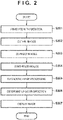
- step S201 the radiation generator 104 drives the radiation generating unit 101 to irradiate the subject 103 with radiation.
- the radiation generator 104 generates radiation by supplying a high-voltage pulse to the radiation generating unit 101 in accordance with the pressing of the exposure switch (not shown).
- the FPD control units 105a and 105b respectively drive the FPDs 102a and 102b to obtain radiation images.
- the FPDs 102a and 102b accumulate electric charge proportional to the doses of radiation in detection elements and output image data based on the accumulated electric charge.
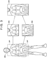
- the FPD control units 105a and 105b save the data as radiation images in the image saving unit 111 or the RAM 116. For example, as shown in Fig.
- the FPD control unit 105a obtains a first radiation image 303 from the FPD 102a arranged in a first imaging range 301.
- the FPD control unit 105b obtains a second radiation image 304 from the FPD 102b arranged in a second imaging range 302.
- step S203 the image correction unit 120 performs image correction for the first radiation image 303 and the second radiation image 304 stored in the image saving unit 111 or the RAM 116. More specifically, the image correction unit 120 performs various types of correction processing, so-called preprocessing, such as offset correction, sensitivity correction, and defective pixel correction for correcting the characteristic variations of the solid-state image sensors which the FPDs 102a and 102b respectively include.
- preprocessing such as offset correction, sensitivity correction, and defective pixel correction for correcting the characteristic variations of the solid-state image sensors which the FPDs 102a and 102b respectively include.
- step S204 the image synthesizing unit 121 synthesizes the first radiation image 303 and the second radiation image 304 having undergone image correction in step S203 into an elongated image 305.
- the image synthesizing unit 121 decides the joining position between the first radiation image 303 and the second radiation image 304, and generates the elongated image 305 by joining the two images.
- the method of deciding a joining position is not specifically limited, for example, it is possible to decide a joining position based on separately obtained information concerning the relative position between the FPD 102a and the FPD 102b.
- it is possible to decide a joining position by applying an image analyzing technique such as template matching to the overlapping area between the first radiation image 303 and the second radiation image 304.
- step S205 the diagnostic image processing unit 122 applies diagnostic image processing to the elongated image 305 synthesized by the image synthesizing unit 121 in step S204. More specifically, the diagnostic image processing unit 122 performs gray level processing, dynamic range processing, and spatial frequency processing for the elongated image 305.
- step S206 the up-down direction determination unit 123 determines the up-down direction of the elongated image 305 synthesized in step S205.
- an elongated image of a subject whose head region is oriented in the upward direction is regarded as an upward elongated image
- an elongated image of a subject whose head region is oriented in the downward direction is regarded as a downward elongated image.
- the elongated image 305 shown in Fig. 3 is an example of an upward elongated image. In this case, it is expected that displaying this elongated image in the upward direction as it is will implement image display suitable for diagnosis.
- an elongated image may be oriented downward like an elongated image 402 shown in Fig. 4 .
- an upward elongated image 401 and the downward elongated image 402 can appear at almost equal frequency.
- the up-down direction determination unit 123 individually estimates the up-down direction of each of the first radiation image 303 and the second radiation image 304, and finally determines the up-down direction of the elongated image 305 based on the respective estimation results.
- the arrangement of the up-down direction determination unit 123 and its processing contents will be described in more detail later.
- step S207 the display unit 113 displays the elongated image 305 having undergone diagnostic image processing in step S205 in accordance with the up-down direction of the elongated image 305 determined in step S206.
- the processing in the radiation imaging apparatus 100 is then completed.
- Fig. 5 is a flowchart showing up-down direction determination processing by the up-down direction determination unit 123 according to this embodiment.
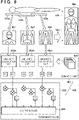
- Fig. 8 is a block diagram showing the more detailed arrangement of the up-down direction determination unit 123 and its processing operation.
- the up-down direction determination unit 123 includes an estimation unit 801 and a determination unit 821.
- the estimation unit 801 estimates the up-down direction of each of a plurality of radiation images.
- the determination unit 821 determines the up-down direction of an elongated image based on the up-down direction estimation result concerning each of the plurality of radiation images which is obtained by the estimation unit 801.
- the estimation unit 801 estimates the direction of the subject in each of the plurality of radiation images.
- the determination unit 821 determines the direction of the subject in the elongated image based on the estimation result concerning each of the plurality of radiation images which is obtained by the estimation unit 801.
- the direction of a subject in a radiation image and the direction of the subject in an elongated image for example, it is possible to use the direction from the foot to the head of the subject or the direction from the head to the foot of the subject.
- the estimation unit 801 estimates a first possibility indicating the possibility of the direction of the head side of a subject in a radiation image being the first direction along the longitudinal direction of the elongated image 305, and a second possibility indicating the possibility of the direction of the head side of a subject being the second direction opposite to the first direction. More specifically, similarity calculation units 802a and 802b individually estimate the up-down direction possibilities (first and second possibilities) of the first radiation image 303 and the second radiation image 304. The determination unit 821 determines the direction of the subject (to be also referred to as the up-down direction of the image hereinafter) in the elongated image 305 based on the first possibility and the second possibility estimated concerning each radiation image by the estimation unit 801.
- the estimation unit 801 and the determination unit 821 determine, based on the estimation result obtained by the estimation unit 801, whether a first direction 841 or a second direction 842 along the longitudinal direction of the elongated image 305 is the direction of the head side of the subject.
- Fig. 8 shows a state in which the first direction 841 is the direction of the head side.
- the corresponding image is an upward image
- the direction of the head side of a subject is the second direction 842
- the corresponding image is a downward image.
- the method of estimating the up-down direction of a radiation image by the estimation unit 801 is not specifically limited, for example, the following estimation method can be used.
- the similarity calculation units 802a and 802b of the estimation unit 801 compare the feature amounts of the radiation images 303 and 304 with those of a plurality of reference images 803 in each of which the direction of the head side of the subject is known.
- the reference images 803 may be stored in, for example, the image saving unit 111.
- the similarity calculation units 802a and 802b calculate similarities U1 and U2 between the radiation images and upward reference images and similarities D1 and D2 between the radiation images and downward reference images.
- the estimation unit 801 uses the similarities U1 and U2 as indices each indicating the first possibility that the head side of the subject in the radiation image is the first direction along the longitudinal direction of the elongated image 305.
- the estimation unit 801 also uses the similarities D1 and D2 as indices each indicating the second possibility that the head side of the subject in the radiation image is the second direction opposite to the first direction.
- the similarity calculation units 802a and 802b each divide a radiation image into a plurality of blocks and compare the feature amounts of the plurality of blocks with those of a corresponding block of each reference image 803, thereby calculating a similarity.
- the similarity calculation unit 802a extracts the feature amounts of the first radiation image 303. More specifically, the similarity calculation unit 802a divides the radiation image 303 into a plurality of blocks each having a predetermined appropriate size and extracts, as feature amounts, for example, a statistic value (minimum, maximum, average, variance, or the like) of pixel values in each block and the intensity and direction of a representative edge of each block.
- a statistic value minimum, maximum, average, variance, or the like
- the similarity calculation unit 802a calculates the similarity U1 between the feature amounts of the reference image 803 as an upward teacher image provided in advance as a correct answer with the feature amounts of the first radiation image 303. For example, the similarity calculation unit 802a calculates the similarity between the feature amounts of each block of the first radiation image 303 with those of a corresponding block of the reference image 803. The similarity calculation unit 802a then calculates the weighted sum of similarities for each block by applying a weight assigned in advance to each block and uses the calculated sum as the similarity U1.
- the similarity U1 can be used as an index indicating the likelihood (first possibility) of the first radiation image 303 being upward.
- step S503 as in step S502, the similarity calculation unit 802a calculates the similarity D1 between the feature amounts of the reference image 803 as a downward teacher image provided in advance as a correct answer with the feature amounts of the first radiation image 303.
- the similarity D1 can be used as an index indicating the likelihood (second possibility) of the first radiation image 303 being downward.
- the similarity calculation unit 802b calculates the similarities U2 and D2 by executing processing similar to that in steps S501 to S503 with respect to the second radiation image 304 in steps S504 to S506.
- the similarities (the similarities U1 and D1 and the similarities U2 and D2) are calculated in parallel concerning two radiation images.
- similarity calculation processing of two radiation images may be performed in series.
- the similarity calculation units 802a and 802b may be integrated into one unit.
- the processing sequence of processing for the first radiation image (steps S501 to S503) and processing for the second radiation image (steps S504 to S506) is not specifically limited. For example, it does not matter whether to perform first the processing for the first radiation image or the processing for the second radiation image data.
- the determination unit 821 determines the direction of the subject in the elongated image based on the result of integrating the first possibilities generated concerning the plurality of radiation images and the result of integrating the second possibilities generated concerning the plurality of radiation images.
- the determination unit 821 determines the up-down direction of the elongated image 305 based on the similarities U1, D1, U2, and D2 calculated by the estimation unit 801 in steps S502, S503, S505, and S506. More specifically, for example, in the determination unit 821, an adder 822a calculates the sum of the similarities U1 and U2 as first possibility indices indicating the likelihoods of the first radiation image 303 and the second radiation image 304 being upward.
- an adder 822b calculates the sum of the similarities D1 and D2 as second possibility indices indicating the likelihoods of the first radiation image 303 and the second radiation image 304 being downward.
- a comparison unit 823 determines the up-down direction of the elongated image 305 by comparing the result (U1 + U2) obtained from the adder 822a with the result (D1 + D2) obtained from the adder 822b. That is, the comparison unit 823 determines the elongated image 305 as upward if U1 + U2 > D1 + D2, and determines the elongated image 305 as downward if U1 + U2 ⁇ D1 + D2.
- This embodiment has exemplified the arrangement configured to perform elongated imaging by using the two sets of the FPDs 102 and the FPD control units 105. Obviously, however, the embodiment can be applied to a case in which elongated imaging is performed by using three or more sets of such units.
- the estimation unit 801 may use, for comparison (similarity calculation), reference images of the plurality of reference images 803 which exhibit matching degrees with the radiation images 303 and 304 equal to or more than a predetermined value.
- the estimation unit 801 may select reference images to be used for comparison based on an imaging regions detected from a radiation image as a comparison target upon classification of the reference images 803 according to imaging regions.
- a known method can be applied to a method of detecting an imaging region from a radiation image.
- an imaging region may be determined from the imaging instruction information provided from an information system such as an HIS or RIS to the radiation imaging apparatus 100 via a network.
- a radiation image and a reference image may be compared upon removal of a region from the radiation image which is not irradiated with radiation.
- a region which is not irradiated with radiation is a region generated mainly by a radiation aperture.
- a known method can be applied to this detection method.
- the first embodiment it is possible to accurately estimate the up-down direction of an elongated image in elongated imaging using a plurality of radiation imaging apparatuses. This makes it possible to provide the radiation imaging apparatus 100 that can display an elongated image in a direction suitable for diagnosis.
- the first embodiment is configured to determine the up-down direction of a synthesized elongated image by using the results of calculating the possibilities of a plurality of radiation images (first and second radiation images) being upward and being downward.
- the second embodiment is configured to determine the up-down direction of an elongated image generated from a plurality of radiation images based on the results of calculating the possibilities of the elongated image being upward and downward in addition to the results of calculating the possibilities of each radiation image being upward and downward. That is, in the second embodiment, an estimation unit 801 estimates the direction of a subject in a radiation image and the direction of the subject in an elongated image 305 generated by an image synthesizing unit 121.
- a determination unit 821 determines the direction of the subject in the elongated image 305, that is, the up-down direction of the elongated image based on the estimation results on a plurality of radiation images (for example, radiation images 303 and 304) and the elongated image by the estimation unit 801. Note that the arrangement of the radiation imaging apparatus 100 according to the second embodiment and its imaging operation for an elongated image are similar to those in the first embodiment ( Figs. 1 and 2 ). Up-down direction determination processing in step S206 will be described below.
- step S206 the up-down direction determination unit 123 regards the elongated image 305 as an up-down direction estimation target in addition to the first radiation image 303 and the second radiation image 304, and determines the up-down direction of the elongated image 305 based on estimation results on the respective images. Determination processing by the up-down direction determination unit 123 according to the second embodiment, that is, processing in step S206 will be described with reference to the flowchart shown in Fig. 6 .
- the up-down direction determination unit 123 calculates similarities U1 and D1 of the first radiation image 303 in steps S501 to S503, and calculates similarities U2 and D2 of the second radiation image 304 in steps S504 to S506. These processes are similar to those described in the first embodiment ( Fig. 5 ).
- the estimation unit 801 of the up-down direction determination unit 123 executes processing similar to that in steps S501 to S503 with respect to the elongated image 305 to calculate a similarity U0 indicating the possibility of the elongated image 305 being upward and a similarity D0 indicating the possibility of the elongated image 305 being downward.
- the estimation unit 801 calculates similarities (the similarities U1 and D1, the similarities U2 and D2, and the similarities U0 and D0) concerning the three images (the first radiation image 303, the second radiation image 304, and the elongated image 305) in parallel.
- the estimation unit 801 may perform calculation processing of the similarities of the three images in series.
- the processing sequence of processing for the first radiation image (steps S501 to S503), processing for the second radiation image (steps S504 to S506), and processing for the elongated image (steps S607 to S609) is not specifically limited. For example, it does not matter whether to perform first the processing for the first radiation image, the processing for the second radiation image, or the processing for the elongated image.
- step S610 the determination unit 821 of the up-down direction determination unit 123 determines the up-down direction of the elongated image 305 based on the similarities U1, D1, U2, D2, U0, and D0 calculated in steps S502, S503, S505, S506, S608, and S609.
- the up-down direction determination unit 123 compares the sum of the similarities U1, U2, and U0 as indices indicating the likelihoods of the first radiation image 303, the second radiation image 304, and the elongated image 305 being upward with the sum of the similarities D1, D2, and D0 as indices indicating the likelihoods of the respective images being downward.
- the up-down direction determination unit 123 determines the elongated image as upward if the sum of the similarities U1, U2, and U0 is large, and determines the elongated image as downward if otherwise.
- the second embodiment it is possible to accurately estimate the direction of a subject in an elongated image (the up-down direction of the elongated image) in elongated imaging using a plurality of radiation detectors. This makes it possible to provide the radiation imaging apparatus 100 that can display an elongated image in an up-down direction suitable for diagnosis.
- the third embodiment will exemplify an arrangement configured to perform elongated imaging by using three sets of FPDs 102 and FPD control units 105.
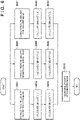
- Fig. 7 is a flowchart showing up-down direction determination processing according to the third embodiment.
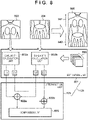
- Fig. 9 is a block diagram for explaining the detailed arrangement of an up-down direction determination unit 123 and its up-down direction determination processing.
- the third embodiment will exemplify an arrangement including three FPDs 102a to 102c and FPD control units 105a to 105c.
- the up-down direction determination unit 123 determines the up-down direction of an elongated image 904.
- the third embodiment is configured to determine an up-down direction based on a first radiation image 901, a second radiation image 902, and a third radiation image 903. That is, a determination unit 821 applies weights to the first and second possibilities described above based on the relative positional relationship between the FPDs 102a to 102c as the plurality of radiation detectors that have obtained the plurality of radiation images 901 to 903. Assume that the FPDs 102a to 102c that obtain the radiation images 901 to 903 are arranged side by side along the longitudinal direction of the elongated image 904, as shown in Fig. 9 . In this case, the determination unit 821 applies a larger weight to the similarity calculated concerning a radiation image from the FPD 102b arranged in the middle than to the similarities calculated concerning radiation images from the FPDs 102a and 102c arranged at end portions.
- a similarity calculation unit 802a of the up-down direction determination unit 123 calculates similarities U1 and D1 of the first radiation image 901.
- a similarity calculation unit 802b of the up-down direction determination unit 123 calculates similarities U2 and D2 of the second radiation image 902. These processes are similar to those in steps S501 to S506 in the first embodiment ( Fig. 5 ).
- the similarity calculation unit 802c calculates similarities U3 and D3 by executing processing similar to that in steps S501 to S503 with respect to the third radiation image 903.
- the calculation units calculate the similarities (the similarities U1 and D1, the similarities U2 and D2, and the similarities U3 and D3) concerning the three radiation images in parallel.
- the calculation units may perform calculation processing of the similarities of the three images in series.
- the processing sequence of processing for the first radiation image 901 (steps S501 to S503), processing for the second radiation image 902 (steps S504 to S506), and processing for the third radiation image 903 (steps S707 to S709) is not specifically limited. It does not matter whether to perform first the processing for the first radiation image, the processing for the second radiation image, or the processing for the third radiation image.
- the number of radiation images (the number of radiation detectors) may be three or more.
- the determination unit 821 determines the up-down direction of an elongated image 305 based on the similarities U1, D1, U2, D2, U3, and D3 calculated in steps S502, S503, S505, S506, S708, and S709. In this case, the determination unit 821 determines, based on the relative positional relationship between the plurality of radiation detectors (FPDs 102a to 102c) that have obtained the plurality of radiation images, the direction of the subject in the image by applying weights to possibilities (similarities) estimated by an estimation unit 801. As described above, in this case, the determination unit 821 applies a larger weight to the radiation image obtained from the radiation detector arranged in the middle than to the radiation images obtained from the radiation detectors arranged at end portions.
- a second radiation image 304 obtained from the FPD 102b reliably includes the subject and is rich in information for estimating an up-down direction. This makes it possible to improve determination accuracy by using a determination method (for example, a method with weighting) with higher importance being placed on image data than on other image data as follows.
- a determination method for example, a method with weighting
- the determination unit 821 multiplies the similarities U1 and D1 output from the similarity calculation unit 802a by a weight ⁇ 1, multiplies the similarities U2 and D2 output from the similarity calculation unit 802b by a weight ⁇ 2, and multiplies the similarities U3 and D3 output from the similarity calculation unit 802c by a weight ⁇ 3.
- a comparison unit 921 integrates weighted similarities and determines the up-down direction of the elongated image 904 as follows:
- weights are decided based on the relative positional relationship between the radiation detectors.
- the determination unit 821 may detect a region of a radiation image which is not irradiated with radiation, and determine the direction of a subject in an elongated image upon reducing a weight to be applied to an estimation result with an increase in the size of the detected region.
- a region which is not irradiated with radiation is a region which is not irradiated with radiation due to, for example, a radiation aperture.
- Such regions can be detected by a known method.
- the determination unit 821 may determine the direction of a subject in an elongated image upon increasing a weight to be applied to an estimation result concerning a radiation image with an increase in the number of feature amounts extracted from the radiation image. Furthermore, alternatively, the determination unit 821 may determine a region of a substance in each radiation image and the direction of the subject in an elongated image by applying a weight corresponding to each determined region to an estimation result on each of a plurality of radiation images. In this case, for example, a large weight is applied to an estimation result on a radiation image in which an imaging region is determined as a head region, and a small weight is applied to an estimation result on a radiation image in which an imaging region is determined as a leg region. Note that a known method can be used to determine an imaging region in a radiation image. Alternatively, an imaging region may be determined from the imaging instruction information provided from an information system such as an HIS or RIS to a radiation imaging apparatus 100 via a network
- the third embodiment it is possible to accurately estimate the up-down direction of an elongated image by considering the placement of FPDs in elongated imaging using a plurality of radiation detectors. According to the third embodiment, this makes it possible to provide a radiation imaging system that can perform screen display in an up-down direction suitable for diagnosis.
- the present invention can also be implemented by supplying a program for implementing one or more functions of each embodiment described above to a system or apparatus via a network or a storage medium and causing one or more processors in the system or apparatus to read and execute the program.
- the present invention can also be implemented by a circuit implementing one or more functions (for example, ASIC).
Landscapes
- Engineering & Computer Science (AREA)
- Health & Medical Sciences (AREA)
- Life Sciences & Earth Sciences (AREA)
- Medical Informatics (AREA)
- Physics & Mathematics (AREA)
- Optics & Photonics (AREA)
- Heart & Thoracic Surgery (AREA)
- Veterinary Medicine (AREA)
- Biophysics (AREA)
- High Energy & Nuclear Physics (AREA)
- Public Health (AREA)
- Nuclear Medicine, Radiotherapy & Molecular Imaging (AREA)
- General Health & Medical Sciences (AREA)
- Pathology (AREA)
- Radiology & Medical Imaging (AREA)
- Biomedical Technology (AREA)
- Animal Behavior & Ethology (AREA)
- Molecular Biology (AREA)
- Surgery (AREA)
- Theoretical Computer Science (AREA)
- General Physics & Mathematics (AREA)
- Computer Vision & Pattern Recognition (AREA)
- Physiology (AREA)
- Human Computer Interaction (AREA)
- Multimedia (AREA)
- Mathematical Physics (AREA)
- Apparatus For Radiation Diagnosis (AREA)
Applications Claiming Priority (2)
| Application Number | Priority Date | Filing Date | Title |
|---|---|---|---|
| JP2017252067A JP7022584B2 (ja) | 2017-12-27 | 2017-12-27 | 放射線撮影装置、画像処理装置及び画像判定方法 |
| PCT/JP2018/041320 WO2019130836A1 (ja) | 2017-12-27 | 2018-11-07 | 放射線撮影装置、画像処理装置及び画像判定方法 |
Publications (3)
| Publication Number | Publication Date |
|---|---|
| EP3714791A1 EP3714791A1 (en) | 2020-09-30 |
| EP3714791A4 EP3714791A4 (en) | 2021-11-10 |
| EP3714791B1 true EP3714791B1 (en) | 2023-01-11 |
Family
ID=67067004
Family Applications (1)
| Application Number | Title | Priority Date | Filing Date |
|---|---|---|---|
| EP18895945.6A Active EP3714791B1 (en) | 2017-12-27 | 2018-11-07 | Radiography device, image processing device, and image determination method |
Country Status (5)
| Country | Link |
|---|---|
| US (1) | US11210809B2 (enExample) |
| EP (1) | EP3714791B1 (enExample) |
| JP (1) | JP7022584B2 (enExample) |
| CN (1) | CN111526795B (enExample) |
| WO (1) | WO2019130836A1 (enExample) |
Families Citing this family (4)
| Publication number | Priority date | Publication date | Assignee | Title |
|---|---|---|---|---|
| JP7414432B2 (ja) * | 2019-09-06 | 2024-01-16 | キヤノン株式会社 | 画像処理装置、画像処理方法、およびプログラム |
| KR102322927B1 (ko) * | 2019-10-22 | 2021-11-04 | 연세대학교 산학협력단 | 인공신경망을 이용한 진단 영상을 구분하기 위한 장치, 이를 위한 방법 및 이 방법을 수행하기 위한 프로그램이 기록된 컴퓨터 판독 가능한 기록매체 |
| CN115835820A (zh) * | 2021-04-23 | 2023-03-21 | 深圳帧观德芯科技有限公司 | 使用具有多个辐射检测器的图像传感器的成像方法 |
| JPWO2024090050A1 (enExample) * | 2022-10-27 | 2024-05-02 |
Family Cites Families (29)
| Publication number | Priority date | Publication date | Assignee | Title |
|---|---|---|---|---|
| JP2000157519A (ja) * | 1998-11-25 | 2000-06-13 | Konica Corp | 画像処理装置 |
| JP2000258861A (ja) | 1999-03-08 | 2000-09-22 | Fuji Photo Film Co Ltd | 蓄積性蛍光体シート及びこれを収容するカセッテ |
| JP2002085392A (ja) * | 2000-09-14 | 2002-03-26 | Konica Corp | 放射線画像処理方法および放射線画像処理装置 |
| JP5361103B2 (ja) * | 2000-10-24 | 2013-12-04 | 株式会社東芝 | 画像処理装置 |
| JP4110074B2 (ja) | 2003-11-05 | 2008-07-02 | キヤノン株式会社 | 放射線画像処理装置、放射線画像処理方法、プログラム及びコンピュータ可読媒体 |
| JP2005202477A (ja) | 2004-01-13 | 2005-07-28 | Fuji Photo Film Co Ltd | 顔画像の天地方向判定方法、画像記録装置および画像再生装置 |
| DE102005036852A1 (de) * | 2005-08-04 | 2007-02-22 | Siemens Ag | Verfahren bzw. "Vorrichtung" zum Ermitteln einer Lage eines Patienten bei einem auf einem medizinischen Bildgebungsverfahren basierenden Erstellen eines Bildes eines Untersuchungsbereichs des Patienten |
| JP4865362B2 (ja) * | 2006-03-01 | 2012-02-01 | キヤノン株式会社 | 画像処理装置及びその制御方法、プログラム |
| JP4740779B2 (ja) * | 2006-03-28 | 2011-08-03 | 株式会社日立メディコ | 放射線撮影装置 |
| JP4682898B2 (ja) * | 2006-03-30 | 2011-05-11 | 株式会社島津製作所 | X線撮影装置 |
| JP4858963B2 (ja) * | 2006-09-14 | 2012-01-18 | 株式会社日立メディコ | 医用画像処理装置 |
| DE102007024452A1 (de) * | 2007-05-25 | 2008-11-27 | Siemens Ag | Verfahren, Tomographiesystem und Bildbearbeitungssystem zur Darstellung tomographischer Aufnahmen eines Patienten |
| JP2009045092A (ja) | 2007-08-13 | 2009-03-05 | Canon Inc | Ct撮影装置及びその制御方法 |
| JP2010094209A (ja) * | 2008-10-15 | 2010-04-30 | Fujifilm Corp | 放射線画像撮影装置 |
| JP5460103B2 (ja) * | 2009-03-31 | 2014-04-02 | キヤノン株式会社 | 放射線撮影装置及びその暗電流補正方法 |
| JP2011004856A (ja) * | 2009-06-24 | 2011-01-13 | Konica Minolta Medical & Graphic Inc | 放射線画像撮影システム |
| JP2012016394A (ja) * | 2010-07-06 | 2012-01-26 | Shimadzu Corp | 放射線断層撮影装置 |
| JP5642451B2 (ja) | 2010-08-18 | 2014-12-17 | 富士フイルム株式会社 | 可搬型放射線撮影装置セット、可搬型放射線撮影装置 |
| JP5496827B2 (ja) * | 2010-08-26 | 2014-05-21 | 富士フイルム株式会社 | 放射線画像撮影システム、放射線画像撮影方法、及びプログラム |
| JP5567963B2 (ja) * | 2010-09-29 | 2014-08-06 | 富士フイルム株式会社 | 画像処理装置、放射線画像システム、画像処理方法およびプログラム |
| JP5601343B2 (ja) * | 2012-05-02 | 2014-10-08 | 株式会社島津製作所 | 放射線撮像装置 |
| JPWO2015045005A1 (ja) | 2013-09-24 | 2017-03-02 | 株式会社島津製作所 | X線撮影装置およびx線撮影方法 |
| JP6289142B2 (ja) * | 2014-02-07 | 2018-03-07 | キヤノン株式会社 | 画像処理装置、画像処理方法、プログラムおよび記憶媒体 |
| DE102014210938A1 (de) * | 2014-06-06 | 2015-12-17 | Siemens Aktiengesellschaft | Verfahren zum Steuern eines medizinischen Gerätes sowie Steuerungssystem für ein medizinisches Gerät |
| JP6497887B2 (ja) * | 2014-10-07 | 2019-04-10 | キヤノン株式会社 | 撮像装置、撮像装置の制御方法、プログラム |
| JP6072102B2 (ja) * | 2015-01-30 | 2017-02-01 | キヤノン株式会社 | 放射線撮影システム及び放射線撮影方法 |
| JP2016202252A (ja) * | 2015-04-15 | 2016-12-08 | キヤノン株式会社 | 放射線撮影システム、放射線撮影システムの制御方法およびプログラム |
| JP6582510B2 (ja) * | 2015-04-15 | 2019-10-02 | コニカミノルタ株式会社 | 放射線画像撮影システム |
| JP6955909B2 (ja) * | 2017-06-12 | 2021-10-27 | キヤノンメディカルシステムズ株式会社 | 画像処理装置 |
-
2017
- 2017-12-27 JP JP2017252067A patent/JP7022584B2/ja active Active
-
2018
- 2018-11-07 EP EP18895945.6A patent/EP3714791B1/en active Active
- 2018-11-07 WO PCT/JP2018/041320 patent/WO2019130836A1/ja not_active Ceased
- 2018-11-07 CN CN201880084102.2A patent/CN111526795B/zh active Active
-
2020
- 2020-06-16 US US16/902,686 patent/US11210809B2/en active Active
Also Published As
| Publication number | Publication date |
|---|---|
| CN111526795A (zh) | 2020-08-11 |
| EP3714791A1 (en) | 2020-09-30 |
| JP7022584B2 (ja) | 2022-02-18 |
| WO2019130836A1 (ja) | 2019-07-04 |
| JP2019115558A (ja) | 2019-07-18 |
| CN111526795B (zh) | 2023-05-02 |
| EP3714791A4 (en) | 2021-11-10 |
| US20200311975A1 (en) | 2020-10-01 |
| US11210809B2 (en) | 2021-12-28 |
Similar Documents
| Publication | Publication Date | Title |
|---|---|---|
| EP3714791B1 (en) | Radiography device, image processing device, and image determination method | |
| US9875544B2 (en) | Registration of fluoroscopic images of the chest and corresponding 3D image data based on the ribs and spine | |
| US6771736B2 (en) | Method for displaying temporal changes in spatially matched images | |
| EP3467838A1 (en) | Diagnostic support system and diagnostic support method | |
| US20160210749A1 (en) | Method and system for cross-domain synthesis of medical images using contextual deep network | |
| JP5828649B2 (ja) | 画像処理装置、画像処理方法、及びコンピュータプログラム | |
| US10930028B2 (en) | Imaging method for computer tomographic system | |
| US9351695B2 (en) | Hybrid dual energy imaging and bone suppression processing | |
| US12340512B2 (en) | Methods and systems for early detection and localization of a lesion | |
| US20190392552A1 (en) | Spine image registration method | |
| JP2021037164A (ja) | 画像解析方法、画像処理装置、骨密度測定装置および学習モデルの作成方法 | |
| US20180204326A1 (en) | Dynamic image processing system | |
| EP3096288A1 (en) | Image processing method, image processing apparatus, x-ray imaging apparatus, and image processing program | |
| EP4377903A1 (en) | Identifying anatomical features | |
| US10123757B2 (en) | Image-processing device, radiation image capture system, image-processing method, and computer-readable storage medium | |
| JP6155177B2 (ja) | 画像診断支援装置に画像処理を実行させるためのコンピュータプログラム、装置及び方法 | |
| JP2020146381A (ja) | 画像処理装置、画像処理システム及びプログラム | |
| EP2343687A2 (en) | Tomographic image generating apparatus, tomographic image generating method, and program for generating tomographic images | |
| US10783699B2 (en) | Sub-voxel refinement of anatomical models | |
| Lehmann et al. | Integrating viability information into a cardiac model for interventional guidance | |
| JP2017000675A (ja) | 医用画像処理装置及びx線撮像装置 | |
| JP6200562B2 (ja) | 画像処理装置、方法及びコンピュータプログラム | |
| JP7772158B2 (ja) | 動態解析装置及びプログラム | |
| EP4491125A1 (en) | Simulated 4d ct surviews using 3d surview and rgb-d camera for improved scan planning | |
| Manohar et al. | Prediction of CRT Response Using a Lead Placement Score Derived from 4DCT |
Legal Events
| Date | Code | Title | Description |
|---|---|---|---|
| STAA | Information on the status of an ep patent application or granted ep patent |
Free format text: STATUS: THE INTERNATIONAL PUBLICATION HAS BEEN MADE |
|
| PUAI | Public reference made under article 153(3) epc to a published international application that has entered the european phase |
Free format text: ORIGINAL CODE: 0009012 |
|
| STAA | Information on the status of an ep patent application or granted ep patent |
Free format text: STATUS: REQUEST FOR EXAMINATION WAS MADE |
|
| 17P | Request for examination filed |
Effective date: 20200623 |
|
| AK | Designated contracting states |
Kind code of ref document: A1 Designated state(s): AL AT BE BG CH CY CZ DE DK EE ES FI FR GB GR HR HU IE IS IT LI LT LU LV MC MK MT NL NO PL PT RO RS SE SI SK SM TR |
|
| AX | Request for extension of the european patent |
Extension state: BA ME |
|
| DAV | Request for validation of the european patent (deleted) | ||
| DAX | Request for extension of the european patent (deleted) | ||
| A4 | Supplementary search report drawn up and despatched |
Effective date: 20211013 |
|
| RIC1 | Information provided on ipc code assigned before grant |
Ipc: A61B 6/00 20060101AFI20211007BHEP |
|
| GRAP | Despatch of communication of intention to grant a patent |
Free format text: ORIGINAL CODE: EPIDOSNIGR1 |
|
| STAA | Information on the status of an ep patent application or granted ep patent |
Free format text: STATUS: GRANT OF PATENT IS INTENDED |
|
| INTG | Intention to grant announced |
Effective date: 20220715 |
|
| GRAS | Grant fee paid |
Free format text: ORIGINAL CODE: EPIDOSNIGR3 |
|
| GRAA | (expected) grant |
Free format text: ORIGINAL CODE: 0009210 |
|
| STAA | Information on the status of an ep patent application or granted ep patent |
Free format text: STATUS: THE PATENT HAS BEEN GRANTED |
|
| AK | Designated contracting states |
Kind code of ref document: B1 Designated state(s): AL AT BE BG CH CY CZ DE DK EE ES FI FR GB GR HR HU IE IS IT LI LT LU LV MC MK MT NL NO PL PT RO RS SE SI SK SM TR |
|
| REG | Reference to a national code |
Ref country code: GB Ref legal event code: FG4D |
|
| REG | Reference to a national code |
Ref country code: CH Ref legal event code: EP |
|
| REG | Reference to a national code |
Ref country code: DE Ref legal event code: R096 Ref document number: 602018045418 Country of ref document: DE |
|
| REG | Reference to a national code |
Ref country code: IE Ref legal event code: FG4D |
|
| REG | Reference to a national code |
Ref country code: AT Ref legal event code: REF Ref document number: 1542915 Country of ref document: AT Kind code of ref document: T Effective date: 20230215 |
|
| REG | Reference to a national code |
Ref country code: LT Ref legal event code: MG9D |
|
| REG | Reference to a national code |
Ref country code: NL Ref legal event code: MP Effective date: 20230111 |
|
| REG | Reference to a national code |
Ref country code: AT Ref legal event code: MK05 Ref document number: 1542915 Country of ref document: AT Kind code of ref document: T Effective date: 20230111 |
|
| PG25 | Lapsed in a contracting state [announced via postgrant information from national office to epo] |
Ref country code: NL Free format text: LAPSE BECAUSE OF FAILURE TO SUBMIT A TRANSLATION OF THE DESCRIPTION OR TO PAY THE FEE WITHIN THE PRESCRIBED TIME-LIMIT Effective date: 20230111 |
|
| PG25 | Lapsed in a contracting state [announced via postgrant information from national office to epo] |
Ref country code: RS Free format text: LAPSE BECAUSE OF FAILURE TO SUBMIT A TRANSLATION OF THE DESCRIPTION OR TO PAY THE FEE WITHIN THE PRESCRIBED TIME-LIMIT Effective date: 20230111 Ref country code: PT Free format text: LAPSE BECAUSE OF FAILURE TO SUBMIT A TRANSLATION OF THE DESCRIPTION OR TO PAY THE FEE WITHIN THE PRESCRIBED TIME-LIMIT Effective date: 20230511 Ref country code: NO Free format text: LAPSE BECAUSE OF FAILURE TO SUBMIT A TRANSLATION OF THE DESCRIPTION OR TO PAY THE FEE WITHIN THE PRESCRIBED TIME-LIMIT Effective date: 20230411 Ref country code: LV Free format text: LAPSE BECAUSE OF FAILURE TO SUBMIT A TRANSLATION OF THE DESCRIPTION OR TO PAY THE FEE WITHIN THE PRESCRIBED TIME-LIMIT Effective date: 20230111 Ref country code: LT Free format text: LAPSE BECAUSE OF FAILURE TO SUBMIT A TRANSLATION OF THE DESCRIPTION OR TO PAY THE FEE WITHIN THE PRESCRIBED TIME-LIMIT Effective date: 20230111 Ref country code: HR Free format text: LAPSE BECAUSE OF FAILURE TO SUBMIT A TRANSLATION OF THE DESCRIPTION OR TO PAY THE FEE WITHIN THE PRESCRIBED TIME-LIMIT Effective date: 20230111 Ref country code: ES Free format text: LAPSE BECAUSE OF FAILURE TO SUBMIT A TRANSLATION OF THE DESCRIPTION OR TO PAY THE FEE WITHIN THE PRESCRIBED TIME-LIMIT Effective date: 20230111 Ref country code: AT Free format text: LAPSE BECAUSE OF FAILURE TO SUBMIT A TRANSLATION OF THE DESCRIPTION OR TO PAY THE FEE WITHIN THE PRESCRIBED TIME-LIMIT Effective date: 20230111 |
|
| PG25 | Lapsed in a contracting state [announced via postgrant information from national office to epo] |
Ref country code: SE Free format text: LAPSE BECAUSE OF FAILURE TO SUBMIT A TRANSLATION OF THE DESCRIPTION OR TO PAY THE FEE WITHIN THE PRESCRIBED TIME-LIMIT Effective date: 20230111 Ref country code: PL Free format text: LAPSE BECAUSE OF FAILURE TO SUBMIT A TRANSLATION OF THE DESCRIPTION OR TO PAY THE FEE WITHIN THE PRESCRIBED TIME-LIMIT Effective date: 20230111 Ref country code: IS Free format text: LAPSE BECAUSE OF FAILURE TO SUBMIT A TRANSLATION OF THE DESCRIPTION OR TO PAY THE FEE WITHIN THE PRESCRIBED TIME-LIMIT Effective date: 20230511 Ref country code: GR Free format text: LAPSE BECAUSE OF FAILURE TO SUBMIT A TRANSLATION OF THE DESCRIPTION OR TO PAY THE FEE WITHIN THE PRESCRIBED TIME-LIMIT Effective date: 20230412 Ref country code: FI Free format text: LAPSE BECAUSE OF FAILURE TO SUBMIT A TRANSLATION OF THE DESCRIPTION OR TO PAY THE FEE WITHIN THE PRESCRIBED TIME-LIMIT Effective date: 20230111 |
|
| REG | Reference to a national code |
Ref country code: DE Ref legal event code: R097 Ref document number: 602018045418 Country of ref document: DE |
|
| PG25 | Lapsed in a contracting state [announced via postgrant information from national office to epo] |
Ref country code: SM Free format text: LAPSE BECAUSE OF FAILURE TO SUBMIT A TRANSLATION OF THE DESCRIPTION OR TO PAY THE FEE WITHIN THE PRESCRIBED TIME-LIMIT Effective date: 20230111 Ref country code: RO Free format text: LAPSE BECAUSE OF FAILURE TO SUBMIT A TRANSLATION OF THE DESCRIPTION OR TO PAY THE FEE WITHIN THE PRESCRIBED TIME-LIMIT Effective date: 20230111 Ref country code: EE Free format text: LAPSE BECAUSE OF FAILURE TO SUBMIT A TRANSLATION OF THE DESCRIPTION OR TO PAY THE FEE WITHIN THE PRESCRIBED TIME-LIMIT Effective date: 20230111 Ref country code: DK Free format text: LAPSE BECAUSE OF FAILURE TO SUBMIT A TRANSLATION OF THE DESCRIPTION OR TO PAY THE FEE WITHIN THE PRESCRIBED TIME-LIMIT Effective date: 20230111 Ref country code: CZ Free format text: LAPSE BECAUSE OF FAILURE TO SUBMIT A TRANSLATION OF THE DESCRIPTION OR TO PAY THE FEE WITHIN THE PRESCRIBED TIME-LIMIT Effective date: 20230111 |
|
| PLBE | No opposition filed within time limit |
Free format text: ORIGINAL CODE: 0009261 |
|
| STAA | Information on the status of an ep patent application or granted ep patent |
Free format text: STATUS: NO OPPOSITION FILED WITHIN TIME LIMIT |
|
| PG25 | Lapsed in a contracting state [announced via postgrant information from national office to epo] |
Ref country code: SK Free format text: LAPSE BECAUSE OF FAILURE TO SUBMIT A TRANSLATION OF THE DESCRIPTION OR TO PAY THE FEE WITHIN THE PRESCRIBED TIME-LIMIT Effective date: 20230111 |
|
| 26N | No opposition filed |
Effective date: 20231012 |
|
| PG25 | Lapsed in a contracting state [announced via postgrant information from national office to epo] |
Ref country code: SI Free format text: LAPSE BECAUSE OF FAILURE TO SUBMIT A TRANSLATION OF THE DESCRIPTION OR TO PAY THE FEE WITHIN THE PRESCRIBED TIME-LIMIT Effective date: 20230111 |
|
| PG25 | Lapsed in a contracting state [announced via postgrant information from national office to epo] |
Ref country code: IT Free format text: LAPSE BECAUSE OF FAILURE TO SUBMIT A TRANSLATION OF THE DESCRIPTION OR TO PAY THE FEE WITHIN THE PRESCRIBED TIME-LIMIT Effective date: 20230111 |
|
| REG | Reference to a national code |
Ref country code: CH Ref legal event code: PL |
|
| PG25 | Lapsed in a contracting state [announced via postgrant information from national office to epo] |
Ref country code: MC Free format text: LAPSE BECAUSE OF FAILURE TO SUBMIT A TRANSLATION OF THE DESCRIPTION OR TO PAY THE FEE WITHIN THE PRESCRIBED TIME-LIMIT Effective date: 20230111 |
|
| PG25 | Lapsed in a contracting state [announced via postgrant information from national office to epo] |
Ref country code: LU Free format text: LAPSE BECAUSE OF NON-PAYMENT OF DUE FEES Effective date: 20231107 |
|
| PG25 | Lapsed in a contracting state [announced via postgrant information from national office to epo] |
Ref country code: CH Free format text: LAPSE BECAUSE OF NON-PAYMENT OF DUE FEES Effective date: 20231130 |
|
| GBPC | Gb: european patent ceased through non-payment of renewal fee |
Effective date: 20231107 |
|
| PG25 | Lapsed in a contracting state [announced via postgrant information from national office to epo] |
Ref country code: MC Free format text: LAPSE BECAUSE OF FAILURE TO SUBMIT A TRANSLATION OF THE DESCRIPTION OR TO PAY THE FEE WITHIN THE PRESCRIBED TIME-LIMIT Effective date: 20230111 Ref country code: LU Free format text: LAPSE BECAUSE OF NON-PAYMENT OF DUE FEES Effective date: 20231107 Ref country code: CH Free format text: LAPSE BECAUSE OF NON-PAYMENT OF DUE FEES Effective date: 20231130 |
|
| REG | Reference to a national code |
Ref country code: BE Ref legal event code: MM Effective date: 20231130 |
|
| REG | Reference to a national code |
Ref country code: IE Ref legal event code: MM4A |
|
| PG25 | Lapsed in a contracting state [announced via postgrant information from national office to epo] |
Ref country code: IE Free format text: LAPSE BECAUSE OF NON-PAYMENT OF DUE FEES Effective date: 20231107 |
|
| PG25 | Lapsed in a contracting state [announced via postgrant information from national office to epo] |
Ref country code: GB Free format text: LAPSE BECAUSE OF NON-PAYMENT OF DUE FEES Effective date: 20231107 |
|
| PG25 | Lapsed in a contracting state [announced via postgrant information from national office to epo] |
Ref country code: BE Free format text: LAPSE BECAUSE OF NON-PAYMENT OF DUE FEES Effective date: 20231130 |
|
| PG25 | Lapsed in a contracting state [announced via postgrant information from national office to epo] |
Ref country code: FR Free format text: LAPSE BECAUSE OF NON-PAYMENT OF DUE FEES Effective date: 20231130 |
|
| PG25 | Lapsed in a contracting state [announced via postgrant information from national office to epo] |
Ref country code: IE Free format text: LAPSE BECAUSE OF NON-PAYMENT OF DUE FEES Effective date: 20231107 Ref country code: GB Free format text: LAPSE BECAUSE OF NON-PAYMENT OF DUE FEES Effective date: 20231107 Ref country code: FR Free format text: LAPSE BECAUSE OF NON-PAYMENT OF DUE FEES Effective date: 20231130 Ref country code: BE Free format text: LAPSE BECAUSE OF NON-PAYMENT OF DUE FEES Effective date: 20231130 |
|
| PG25 | Lapsed in a contracting state [announced via postgrant information from national office to epo] |
Ref country code: BG Free format text: LAPSE BECAUSE OF FAILURE TO SUBMIT A TRANSLATION OF THE DESCRIPTION OR TO PAY THE FEE WITHIN THE PRESCRIBED TIME-LIMIT Effective date: 20230111 |
|
| PG25 | Lapsed in a contracting state [announced via postgrant information from national office to epo] |
Ref country code: BG Free format text: LAPSE BECAUSE OF FAILURE TO SUBMIT A TRANSLATION OF THE DESCRIPTION OR TO PAY THE FEE WITHIN THE PRESCRIBED TIME-LIMIT Effective date: 20230111 |
|
| PGFP | Annual fee paid to national office [announced via postgrant information from national office to epo] |
Ref country code: DE Payment date: 20241022 Year of fee payment: 7 |
|
| PG25 | Lapsed in a contracting state [announced via postgrant information from national office to epo] |
Ref country code: CY Free format text: LAPSE BECAUSE OF FAILURE TO SUBMIT A TRANSLATION OF THE DESCRIPTION OR TO PAY THE FEE WITHIN THE PRESCRIBED TIME-LIMIT; INVALID AB INITIO Effective date: 20181107 |
|
| PG25 | Lapsed in a contracting state [announced via postgrant information from national office to epo] |
Ref country code: HU Free format text: LAPSE BECAUSE OF FAILURE TO SUBMIT A TRANSLATION OF THE DESCRIPTION OR TO PAY THE FEE WITHIN THE PRESCRIBED TIME-LIMIT; INVALID AB INITIO Effective date: 20181107 |
|
| PG25 | Lapsed in a contracting state [announced via postgrant information from national office to epo] |
Ref country code: TR Free format text: LAPSE BECAUSE OF FAILURE TO SUBMIT A TRANSLATION OF THE DESCRIPTION OR TO PAY THE FEE WITHIN THE PRESCRIBED TIME-LIMIT Effective date: 20230111 |