EP3712589A1 - Test apparatus and method for key roof block collapse in bidirectional static-dynamic loading - Google Patents
Test apparatus and method for key roof block collapse in bidirectional static-dynamic loading Download PDFInfo
- Publication number
- EP3712589A1 EP3712589A1 EP18916862.8A EP18916862A EP3712589A1 EP 3712589 A1 EP3712589 A1 EP 3712589A1 EP 18916862 A EP18916862 A EP 18916862A EP 3712589 A1 EP3712589 A1 EP 3712589A1
- Authority
- EP
- European Patent Office
- Prior art keywords
- horizontal
- vertical
- model sample
- key
- stress
- Prior art date
- Legal status (The legal status is an assumption and is not a legal conclusion. Google has not performed a legal analysis and makes no representation as to the accuracy of the status listed.)
- Granted
Links
- 238000012360 testing method Methods 0.000 title claims abstract description 58
- 238000000034 method Methods 0.000 title claims abstract description 50
- 230000002457 bidirectional effect Effects 0.000 title claims abstract description 45
- 238000012544 monitoring process Methods 0.000 claims abstract description 75
- 230000008569 process Effects 0.000 claims abstract description 42
- 238000005259 measurement Methods 0.000 claims abstract description 36
- 230000004044 response Effects 0.000 claims abstract description 30
- 238000010998 test method Methods 0.000 claims abstract description 14
- 230000007246 mechanism Effects 0.000 claims abstract description 10
- 230000009471 action Effects 0.000 claims abstract description 7
- 230000015572 biosynthetic process Effects 0.000 claims abstract description 7
- 230000003068 static effect Effects 0.000 claims description 39
- 239000000463 material Substances 0.000 claims description 36
- 239000013307 optical fiber Substances 0.000 claims description 27
- XEEYBQQBJWHFJM-UHFFFAOYSA-N Iron Chemical compound [Fe] XEEYBQQBJWHFJM-UHFFFAOYSA-N 0.000 claims description 24
- 238000006073 displacement reaction Methods 0.000 claims description 18
- 238000004379 similarity theory Methods 0.000 claims description 14
- 238000001723 curing Methods 0.000 claims description 13
- 229910052742 iron Inorganic materials 0.000 claims description 12
- 239000002002 slurry Substances 0.000 claims description 12
- 238000004519 manufacturing process Methods 0.000 claims description 11
- NJPPVKZQTLUDBO-UHFFFAOYSA-N novaluron Chemical compound C1=C(Cl)C(OC(F)(F)C(OC(F)(F)F)F)=CC=C1NC(=O)NC(=O)C1=C(F)C=CC=C1F NJPPVKZQTLUDBO-UHFFFAOYSA-N 0.000 claims description 10
- 239000002243 precursor Substances 0.000 claims description 10
- 230000008859 change Effects 0.000 claims description 6
- 238000010276 construction Methods 0.000 claims description 6
- 230000001902 propagating effect Effects 0.000 claims description 5
- 229910000831 Steel Inorganic materials 0.000 claims description 4
- 238000004581 coalescence Methods 0.000 claims description 4
- 239000010959 steel Substances 0.000 claims description 4
- 238000005336 cracking Methods 0.000 claims description 3
- 238000005192 partition Methods 0.000 claims description 3
- 238000004088 simulation Methods 0.000 claims description 3
- 238000003466 welding Methods 0.000 claims description 3
- 239000011435 rock Substances 0.000 abstract description 19
- 239000000523 sample Substances 0.000 description 112
- 238000005422 blasting Methods 0.000 description 11
- 230000004888 barrier function Effects 0.000 description 8
- 238000009434 installation Methods 0.000 description 8
- 230000005856 abnormality Effects 0.000 description 7
- 238000010586 diagram Methods 0.000 description 5
- 238000005070 sampling Methods 0.000 description 5
- 238000003860 storage Methods 0.000 description 5
- 230000002265 prevention Effects 0.000 description 4
- 230000006378 damage Effects 0.000 description 3
- 238000002955 isolation Methods 0.000 description 3
- 238000012806 monitoring device Methods 0.000 description 3
- 238000011160 research Methods 0.000 description 3
- 238000012546 transfer Methods 0.000 description 3
- 239000000853 adhesive Substances 0.000 description 2
- 230000001070 adhesive effect Effects 0.000 description 2
- 238000013459 approach Methods 0.000 description 2
- 230000003247 decreasing effect Effects 0.000 description 2
- 238000011161 development Methods 0.000 description 2
- 238000002474 experimental method Methods 0.000 description 2
- 238000011835 investigation Methods 0.000 description 2
- 230000000630 rising effect Effects 0.000 description 2
- XLYOFNOQVPJJNP-UHFFFAOYSA-N water Substances O XLYOFNOQVPJJNP-UHFFFAOYSA-N 0.000 description 2
- 239000006004 Quartz sand Substances 0.000 description 1
- VYPSYNLAJGMNEJ-UHFFFAOYSA-N Silicium dioxide Chemical compound O=[Si]=O VYPSYNLAJGMNEJ-UHFFFAOYSA-N 0.000 description 1
- 230000009286 beneficial effect Effects 0.000 description 1
- 239000004568 cement Substances 0.000 description 1
- 239000003638 chemical reducing agent Substances 0.000 description 1
- 125000004122 cyclic group Chemical group 0.000 description 1
- 230000034994 death Effects 0.000 description 1
- 230000000694 effects Effects 0.000 description 1
- 229910052602 gypsum Inorganic materials 0.000 description 1
- 239000010440 gypsum Substances 0.000 description 1
- 238000009830 intercalation Methods 0.000 description 1
- 230000002687 intercalation Effects 0.000 description 1
- 238000005065 mining Methods 0.000 description 1
- 238000012986 modification Methods 0.000 description 1
- 230000004048 modification Effects 0.000 description 1
- 230000000737 periodic effect Effects 0.000 description 1
- 238000002360 preparation method Methods 0.000 description 1
- 238000006467 substitution reaction Methods 0.000 description 1
- 230000001360 synchronised effect Effects 0.000 description 1
- 230000035899 viability Effects 0.000 description 1
Images


Classifications
-
- G—PHYSICS
- G01—MEASURING; TESTING
- G01M—TESTING STATIC OR DYNAMIC BALANCE OF MACHINES OR STRUCTURES; TESTING OF STRUCTURES OR APPARATUS, NOT OTHERWISE PROVIDED FOR
- G01M7/00—Vibration-testing of structures; Shock-testing of structures
- G01M7/08—Shock-testing
Abstract
Description
- The invention belongs to the technical field of early warning of mine disasters, and relates to a key roof block fall test device and method based on bidirectional static-dynamic loading.
- Most roof fall, as a common disaster in stope, is caused by an excessive exposure of the goaf or breakage of the roof strata, and generally occurs in the form of large-scale entire fall. As for roadways under a poor support condition, several rock blocks may fall occasionally, and this phenomenon is referred to as small-scale local fall. Regardless of the large-scale entire fall or the small-scale local fall, the instability of roof rock generally results from the instability of key blocks. The fall of the key blocks may destroy the static equilibrium of the whole rock stratum, which results in falling of other rock blocks like the domino effect in turn. Consequentially, it may cause personnel injuries or death and damage or destroy to equipment. Therefore, it is of great significance to study the instability mechanism of key roof blocks to provide theoretical support for investigation of roof fall accidents and for early warning and prevention of the roof fall accidents.
- In most cases, instability fall of the key roof blocks is caused by disturbances. There are many disturbances that may induce the instability of the key roof blocks, and blasting disturbance is the most common one that may lead to roof fall accidents. Hence, it is necessary to study the instability process of the key roof blocks under the disturbance of dynamic stress waves. Due to the fact that the blasting site on the mining field is not fixed and has to be changed occasionally as required by production, and even, blasting may be carried out on different sites at the same time. Therefore, it is fallacious for roadways or goafs to merely consider the stress wave disturbance in only one direction. It has become an irresistible trend to study bidirectional stress wave disturbances. Meanwhile, on account of the continuous static horizontal and vertical crustal stress applied to the roadways/goafs, the stress condition leading to the instability of the key roof blocks should be a bidirectional static-dynamic stress condition. Nowadays, most researches on roof fall disasters of mines are concentrated on the upper limit analysis of falling arches, the periodic roof pressure rule, and reasonable support. There have not yet been any bidirectional static-dynamic combined tests or relevant devices for instability study of the key roof blocks. In view of this, it is necessary to invent a corresponding test device and method to study the instability falling mechanism of the key roof blocks and to seek precursor information and evolution laws of the instability process to lay a theoretical foundation for disaster prevention and early warning.
- To solve the aforesaid technical problems, the objective of the invention is to provide a key roof block fall test device and method based on bidirectional static-dynamic loading to study the instability falling process and mechanism of key roof blocks and to seek precursor information and evolution laws of the instability process to lay a theoretical foundation for disaster prevention and early warning.
- The invention provides a key roof block fall test device based on bidirectional static-dynamic loading, which comprises an overall frame, a horizontal pressure loading system, a vertical pressure loading system, a horizontal pendulum-hammer impact disturbance system, a vertical drop-hammer impact disturbance system, an incident stress wave monitoring system and a response measurement and monitoring system, wherein:
- The overall frame is used to carry other systems, provide a reactive force and accommodate a model sample;
- The horizontal pressure loading system is mounted on one side of the overall frame and is used to apply a horizontal static load to the model sample;
- The vertical pressure loading system is mounted on an upper portion of the overall frame and is used to apply a vertical static load to the model sample;
- The horizontal pendulum-hammer impact disturbance system is mounted on the other side of the overall frame and applies a horizontal dynamic load to the model sample by hitting against a horizontal incident rod;
- The vertical drop-hammer impact disturbance system is mounted on the upper portion of the overall frame and applies a vertical dynamic load to the model sample by hitting against a vertical incident rod;
- The incident stress wave monitoring system is used to monitor incident stress waves on the horizontal incident rod and the vertical incident rod; and
- The response measurement and monitoring system is used to realize various types of response monitoring.
- According to the key roof block fall test device based on bidirectional static-dynamic loading of the invention, the overall frame comprises a steel frame body, two centering mandrels, a horizontal sliding rail, two movable cushion blocks, two vertical sliding rails and two buffer devices;
- The frame body is formed by welding an upper frame, a lower frame and two side frames, the model sample is loaded in a lower space inside the frame body, and backing plates are arranged on contact surfaces of the model sample with the horizontal pressure loading system, the horizontal pendulum-hammer impact disturbance system, the vertical pressure loading system and the vertical drop-hammer impact disturbance system;
- The two centering mandrels are mounted on one side frame of the frame body through threaded rods and are used to adjust the central position of the model sample;
- The horizontal sliding rail is arranged on the lower frame of the frame body, and the two movable cushion blocks are arranged on the horizontal sliding rail and are used to support the bottom of the model sample and guarantee that the horizontal stress of the model sample is uniform; and
- The two vertical sliding rails are respectively arranged on the side frames above the model sample, and the two buffer devices are symmetrically arranged at the lower ends of the corresponding vertical sliding rails, respectively.
- According to the key roof block fall test device based on bidirectional static-dynamic loading of the invention, the horizontal pressure loading system is mounted on one side frame of the frame body, is disposed opposite to the centering mandrels, and comprises a horizontal hydraulic cylinder and a horizontal loading plate, wherein the horizontal loading plate is mounted on a pressure head of the horizontal hydraulic cylinder and is used to apply the horizontal static load to the model sample uniformly; and
- The vertical pressure loading system is mounted on the upper frame of the frame body and comprises two vertical hydraulic cylinders and a vertical loading plate, wherein the two vertical hydraulic cylinders are symmetrically mounted on the upper frame, and the vertical loading plate is mounted on pressure heads of the two vertical hydraulic cylinders, is used to apply the vertical static load to the model sample, and has two ends mounted on the vertical sliding rails through pulleys.
- According to the key roof block fall test device based on bidirectional static-dynamic loading of the invention, the vertical drop-hammer impact disturbance system is mounted on the upper frame of the frame body and comprises a support, an electromagnetic chuck, a drop hammer, a cross beam and the vertical incident rod, wherein the drop hammer is mounted in the middle of the cross beam, the cross beam is assembled on the support and is able to slide upwards or downwards along the support to allow the drop hammer to freely and accurately fall to hit against the vertical incident rod, the vertical incident rod penetrates through the upper frame of the frame body and the vertical loading plate to act on the backing plate on the upper side of the model sample to apply the vertical hydraulic load to the model sample, the electromagnetic chuck is arranged at the upper end of the support and is used to attract the drop hammer, and the drop hammer is released by controlling a switch of the electromagnetic chuck.
- According to the key roof block fall test device based on bidirectional static-dynamic loading of the invention, the horizontal pendulum-hammer impact disturbance system is arranged on one side of the frame body, is located on the same side as the centering mandrels, and comprises a pedestal, a pendulum rod, a pendulum hammer , the horizontal incident rod, three sliding supports, an index dial and a brake valve, wherein the pendulum hammer is mounted at one end of the pendulum rod, and the other end of the pendulum rod is mounted on the pedestal; the horizontal incident rod penetrates through the corresponding side frame of the frame body to contact with the backing plate on one side of the model sample; the pendulum rod is manually lifted, the brake valve is locked to fix the pendulum height, and then the brake valve is unlocked to release the pendulum rod, so that the pendulum hammer hits against the horizontal incident rod to generate horizontally propagating impact stress waves to apply the horizontal dynamic load to the model sample; and the sliding support supports the horizontal incident rod, and the index dial is arranged at the top of the pedestal and is used to quantitatively determine impact energy of the pendulum hammer.
- According to the key roof block fall test device based on bidirectional static-dynamic loading of the invention, the response measurement and monitoring system comprises one or more laser displacement meters, one or more strain acquisition instruments, one or more pressure cell sensors, one or more optical-fiber tensile stress sensors, one or more two-dimensional speckle strain measurement systems, one or more acoustic emission signal acquisition devices, and one or more BOTDR distributed optical-fiber strain testers.
- The invention further provides a key roof block fall test method based on bidirectional static-dynamic loading, which comprises the following steps:
- Step 1: constructing an overall roadway model sample according to the investigated field condition and similarity theory, and calculating a boundary force condition of the overall roadway model sample according to an original crustal stress;
- Step 2: placing the overall roadway model sample into an overall frame, and applying a horizontal static load and a vertical static load to the overall roadway model sample by a horizontal pressure loading system and a vertical pressure loading system according to the boundary force condition;
- Step 3: repeatedly and cyclically applying dynamic loads to the overall roadway model sample by a horizontal pendulum-hammer impact disturbance system and a vertical drop-hammer impact disturbance system, recording an incident stress waveform by an incident stress wave monitoring system, and recording stress state data around a key block, acoustic emission data and surface strain field data of the model sample by a response measurement and monitoring system; and observing the crack propagation rule, the formation process of the key block, the instability sliding process of the key block, and the roadway destroy mode under the dynamic disturbance;
- Step 4: stopping the application of the dynamic loads when the key roof block is destroyed or falls, and analyzing initial stress conditions of a roadway and a key block according to the recoded stress state data around the key block; and analyzing the crack propagation process of the key roof block according to the recorded incident stress waveform, acoustic emission data and surface strain field data;
- Step 5: constructing a key block model sample according to the investigated field condition and the similarity theory;
- Step 6: placing the key block model sample into the overall frame, and applying a horizontal static load and a vertical static load to the key block model sample by the horizontal pressure loading system and the vertical pressure loading system, with the initial stress condition of the key roof block obtained in
Step 4 as the boundary force condition of the key block model sample; - Step 7: repeatedly and cyclically applying dynamic loads to the key block model sample by the horizontal pendulum-hammer impact disturbance system and the vertical drop-hammer impact disturbance system, recording an incident waveform by the incident stress wave monitoring system, and recording various monitoring data by the response measurement and monitoring system; and observing the crack propagation rule of the key block and the instability sliding process after crack coalescence; and
- Step 8: stopping the application of the dynamic loads when the key roof block is destroyed or falls, analyzing the action mechanism of impact disturbances leading to instability sliding of the key block, according to the recorded monitoring data, observing the data changes, analyzing the change rule, and seeking the critical instability condition and precursor information of the key block.
- According to the key roof block fall test method based on bidirectional static-dynamic loading of the invention, the response measurement and monitoring system comprises one or more laser displacement meters, one or more strain acquisition instruments, one or more pressure cell sensors, one or more optical-fiber tensile stress sensors, one or more two-dimensional speckle strain measurement systems, one or more acoustic emission signal acquisition devices, and one or more BOTDR distributed optical-fiber strain testers.
- According to the key roof block fall test method based on bidirectional static-dynamic loading of the invention, the construction of the overall roadway model sample in Step 1 specifically comprises:
- Step 1.1: defining an appropriate simulation scope according to the investigated field condition, determining a dimension similarity ratio, a strength similarity ratio, a density similarity ratio and a stress similarity ratio according to the similarity theory, and calculating the dimension, density and strength of the test model;
- Step 1.2: selecting an appropriate similar material according to the calculated model density and model strength, and selecting an optimum similar material formula and curing method by multiple orthogonal experimental comparisons;
- Step 1.3: manufacturing the overall roadway model sample according to the obtained model dimension and similar material formula, wherein the specific manufacturing process includes: ① erecting a square model, and disposing a roadway partition in the middle of the model; ② preparing and pouring similar material slurry according to the selected optimum similar material formula; ③ inserting thin iron sheets into a roadway roof according to a pre-determined shape and dimension of the key block to pre-form roof cracks; ④ embedding the pressure cell sensors around the key block; ⑤ curing a similar model according to the optimum curing method, and pulling the thin iron sheet out of the roadway roof after initial setting is finished; and ⑥ continuing to cure the similar model to an expected strength; and
- Step 1.4: calculating the boundary force condition of the overall roadway model sample according to the original crustal stress and the stress similarity ratio.
- According to the key roof block fall test method based on bidirectional static-dynamic loading of the invention, the construction of the key block model sample in
Step 5 specifically comprises: - Step 5.1: scaling up the dimension similarity ratio on the basis of the similarity theory, simulating the local scope of the key block, and determining an appropriate key block model sample dimension; and
- Step 5.2: manufacturing the trapezoidal key block model sample according to the key block model sample dimension, wherein the specific manufacturing process includes: ① erecting a template, and prearranging two non-through thin iron sheets at pre-determined positions; ② preparing and pouring similar material slurry according to the selected optimum similar material formula; ③ embedding the optical-fiber tensile stress sensors and the pressure cell sensors around the key block, embedding a distributed optical fiber in the bottom of the model, consolidating the similar material slurry by vibration, and flattening the surface; ④ curing the similar material slurry in an appropriate environment according to the optimum curing method; ⑤ pulling out the thin iron sheet used for pre-cracking after the similar material is initially set; and ⑥ continuing to cure the similar material to an expected strength.
- The key roof block fall test device and method based on bidirectional static-dynamic loading of the invention at least have the following beneficial effects:
- (1) The invention carries out a research on roof fall accidents based on the view that roof fall is caused by key block instability, and it is suitable for studying most roof fall accidents.
- (2) The invention not only observes and studies the key block instability process from an overall perspective of roadways, but also deeply studies precursor information of key block instability from a local perspective of key blocks, and the development law of instability falling of the key blocks can be analyzed according to the experiment phenomena and monitoring data.
- (3) The invention takes bidirectional dynamic disturbances into consideration, thus being more adaptable to the situation where the roadway roof suffers from bidirectional dynamic disturbances due to the unfixed blasting site in the field and the possibility of synchronous blasting on different sites.
- (4) The invention adopts bidirectional static-dynamic loading, thus being more adaptable to the situation wherein the key roof block of the roadway is subjected to the crustal stress and the blasting disturbance at the same time.
- (5) The pendulum-hammer impact and drop-hammer impact provided by the invention can create an accurate and controllable bidirectional dynamic disturbance condition.
-
-
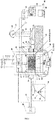
FIG 1 is a structural diagram of a key roof block fall test device based on bidirectional static-dynamic loading of the invention; -
FIG 2 is a structural diagram of a safety isolation barrier of the invention; -
FIG 3 is a structural diagram of a sample pre-installation auxiliary frame of the invention; -
FIG 4 is a test diagram of a key roof block fall test method based on bidirectional static-dynamic loading in a first working condition of the invention; -
FIG 5 is a schematic diagram of auxiliary installation of a key block sample by means of the sample pre-installation auxiliary frame in a second working condition. - A key roof block fall test device and method based on bidirectional static-dynamic loading of the invention are expounded below with reference to the accompanying drawings.
- As shown in
FIG. 1 , the key roof block fall test device based on bidirectional static-dynamic loading comprises an overall frame, a horizontal pressure loading system, a vertical pressure loading system, a horizontal pendulum-hammer impact disturbance system, a vertical drop-hammer impact disturbance system, an incident stress wave monitoring system, a response measurement and monitoring system and ahydraulic power system 33. - The overall frame is used to carry other systems, provide a reactive force and accommodate a model sample, and comprises a
steel frame body 14, two centeringmandrels 17, a horizontal slidingrail 13, two movable cushion blocks 12, two vertical slidingrails 8 and twobuffer devices 15. Theframe body 14 is formed by welding an upper frame, a lower frame and two side frames, and through holes and threaded holes are reserved as required. The model sample is loaded in a lower space inside theframe body 14, andbacking plates 16 are arranged on contact surfaces of the model sample with the horizontal pressure loading system, the vertical pressure loading system, the horizontal pendulum-hammer impact disturbance system and the vertical drop-hammer impact disturbance system. The two centeringmandrels 17 are mounted on one side frame of theframe body 14 through threaded rods and are used to adjust the central position of the model sample. In this embodiment, the two centeringmandrels 17 are arranged on the right side frame of theframe body 14. The horizontal slidingrail 13 is mounted on the lower frame of theframe body 14 through bolts, and the two movable cushion blocks 12 are arranged on the horizontal slidingrail 13 and are used to support the bottom of the model sample and guarantee that the horizontal stress of the model sample is uniform, so that when a key block instability test is carried out, surrounding rock blocks on the two sides of a key block model sample can horizontally move freely. The two vertical slidingrails 8 are respectively arranged on the side frames above the model sample and can maintain horizontal movement and descending of avertical loading plate 7 of the vertical pressure loading system. The twobuffer devices 15 are symmetrically arranged at the lower ends of the corresponding vertical slidingrails 8, respectively and can effectively reduce an impact of thevertical loading plate 7 after the sample is destroyed or loses stability. - The horizontal pressure loading system is mounted on one side of the overall frame and is used to apply a horizontal static load to the model sample. The horizontal pressure loading system is mounted on one side frame of the
frame body 14, isdisposed opposite to the centeringmandrels 17, and comprises a horizontalhydraulic cylinder 10 and ahorizontal loading plate 11; in this embodiment, the horizontalhydraulic cylinder 10 is mounted on the left side frame of theframe body 14 to provide the horizontal static load; and thehorizontal loading plate 11 is mounted on a pressure head of the horizontalhydraulic cylinder 10 and is used to apply the horizontal static load to the model sample and to change the force application area. A high-pressure oil pipe 35 of thehydraulic power system 33 is connected to the horizontalhydraulic cylinder 10 to provide power for the horizontalhydraulic cylinder 10. - The vertical pressure loading system is mounted on an upper portion of the overall frame and is used to apply a vertical static load to the model sample. The vertical pressure loading system is mounted on the upper frame of the
frame body 14 and comprises two verticalhydraulic cylinders 6 and avertical loading plate 7, wherein the two verticalhydraulic cylinders 6 are symmetrically mounted on the upper frame and are symmetrically disposed on two sides of avertical incident rod 5 of the vertical drop-hammer impact disturbance system; and thevertical loading plate 7 is mounted on pressure heads of the two verticalhydraulic cylinders 6, has two ends mounted on the vertical slidingrails 8 through pulleys, and is able to transmit the vertical static load to the model sample without generating any torque in the loading process. A high-pressure oil pipe 35 of thehydraulic power system 33 is connected to the two verticalhydraulic cylinders 6 to provide power for the verticalhydraulic cylinders 6. - The vertical drop-hammer impact disturbance system is mounted on the upper portion of the overall frame and applies a vertical dynamic load to the sample model by hitting against the
vertical incident rod 5. The vertical drop-hammer impact disturbance system is mounted on the upper frame of theframe body 14 and comprises asupport 4, an electromagnetic chuck 1, a drop hammer 3, across beam 2 and thevertical incident rod 5, wherein the drop hammer 3 is mounted in the middle of thecross beam 2, and thecross beam 2 is assembled on thesupport 4 and is able to slide upwards or downwards along thesupport 4 to allow the drop hammer 3 to accurately and freely fall to hit against thevertical incident rod 5; thevertical incident rod 5 penetrates through the upper frame of theframe body 14 and thevertical loading plate 7 to act on thebacking plate 16 on the upper side of the model sample to apply the vertical dynamic load to the model sample; and the electromagnetic chuck 1 is arranged at the upper end of thesupport 4 and is used to attract the drop hammer 3, and a switch of the electromagnetic chuck 1 can be controlled to release the drop hammer 3. - The horizontal pendulum-hammer impact disturbance system is mounted on the other side of the overall frame and applies a horizontal dynamic load to the model sample by hitting against a
horizontal incident rod 19. The horizontal pendulum-hammer impact disturbance system is arranged on one side of the frame body 14, is located on the same side as the centering mandrels 17, and comprises a pedestal 23, a pendulum rod 22, a pendulum hammer 24, a horizontal incident rod 19, three sliding supports 18, an index dial 21 and a brake valve 20, wherein the pendulum hammer 24 is mounted at one end of the pendulum rod 22, and the other end of the pendulum rod 22 is mounted on the pedestal 23; the horizontal incident rod 19 penetrates through the corresponding side frame of the frame body 14 to contact with the backing plate 16 on the corresponding side of the model sample; the pendulum rod 22 is manually lifted, the brake valve 20 is locked to fix the pendulum height, and then the brake valve 20 is unlocked to release the pendulum rod 22, so that the pendulum hammer 24 hits against the horizontal incident rod 19 to generate horizontally propagating impact stress waves to apply the horizontal dynamic load to the model sample; the sliding support 18 supports the horizontal incident rod 19, the index dial 21 is arranged at the top of the pedestal 23 and is used to quantitatively determine the impact energy of the pendulum hammer 24, and the brake valve 20 is used to control the release of the pendulum rod 22; and the pedestal 23 and the sliding support 18 are both mounted on a concrete base 25. - The incident stress wave monitoring system is used to monitor incident stress waves on the
horizontal incident rod 19 and thevertical incident rod 5 and comprises strain gauges 49, a signal amplifier 43, anoscilloscope 44, aswitchboard 45 and acomputer 46, wherein the strain gauges 49 are respectively pasted on thehorizontal incident rod 19 and thevertical incident rod 5 to form a full-bridge circuit and are used to monitor the incident stress waves on thehorizontal incident rod 19 and thevertical incident rod 5; the signal amplifier 43 is connected between theoscilloscope 44 and the strain gauge 49 circuit and is used to amplify original signals of the strain gauges; theoscilloscope 44 is used to collect and record voltage signals of the strain gauges; and thecomputer 46 is used to store and analyze the voltage signals of the strain gauges and convert the voltage signals into stress wave signals. - The response measurement and monitoring system is used to realize various types of response monitoring, including surface fixed-point displacement monitoring, surface fixed-point strain monitoring, internal fixed-point pressure monitoring, surface strain/displacement field monitoring, acoustic emission monitoring, surface displacement monitoring, and the like, and the specific test method will be described below. The response measurement and monitoring system comprises one or more laser displacement meters 28, one or more strain acquisition instruments, one or more pressure cell sensors, one or more optical-fiber tensile stress sensors, one or more two-dimensional speckle strain measurement systems, and one or more acoustic emission signal acquisition devices consisting of acoustic emission probes and acoustic emission signal acquisition instruments, distributed
optical fibers 26, and BOTDR distributed optical-fiber strain testers 27. Part of these devices is not shown in the figures. - As shown in
FIG. 2, FIG. 3 andFIG. 4 , the test device further comprisessafety isolation barriers 38, a verticalload transfer sleeve 9, a sample pre-installationauxiliary frame 39 andbacking plates 16, wherein thesafety isolation barriers 38 are mounted on the front side and the back side of theframe body 14 and are used to isolate a test system from workers to guarantee the safety of the workers in the test process; the verticalload transfer sleeve 9 is used to extend the transfer distance of a vertical pressure in the case of insufficient stroke of the pressure heads of the verticalhydraulic cylinders 6; the sample pre-installationauxiliary frame 39 consists of asupport plate 40, a liftingadjustment bolt 41 and asteel frame 42, is used for auxiliary installation of a middle key block sample, is located below theframe body 14 to support the middle key block sample, and is removed after all samples are installed and clamped; and thebacking plates 16 are disposed between thehorizontal loading plate 11 and the sample as well as between thevertical loading plate 7 and the sample, and are used to change the load application area. - The impact of earthquakes and blasting disturbances on the key block is mainly reflected in the influence of the propagation of blasting stress waves. The vertical drop-hammer impact disturbance system can simulate vertical stress waves propagating from top to bottom in the roof, and the horizontal pendulum-hammer impact disturbance system can simulate horizontal stress waves propagating from right to left in the surrounding rock, so that the influence of stress wave disturbances in different directions on the stability of the key block are studied.
- In order to investigate the rock crack propagation and instability falling process of a key roof block of a roadway/goaf, first of all, it is necessary to acquire the stress state of surrounding rock around the roadway/goaf and to analyze the stress condition of the key roof block. On this basis, an experimental investigation about the stability of the key block is carried out independently. Hence, the test method of the invention includes two working conditions. First working condition: a bidirectional static-dynamic loading disturbance test of an overall roadway model sample, as shown in
FIG. 1 , wherein this test is carried out to explore the initial stress state of surrounding rock around the roadway/goaf and the initial stress condition of key roof block and observe the crack propagation rule, the formation process and the instability process of the key block in the disturbance process. - Second working condition: a bidirectional static-dynamic loading disturbance instability test of a key roof block model sample, shown in
FIG. 5 , wherein on the basis of test results of the first working condition, the key roof block and the surrounding block on both sides are abstracted to carry out the bidirectional static-dynamic loading disturbance test to more accurately explore the rule of crack propagation caused by stress waves, the critical condition of instability sliding of the key block, and the action mechanism of instability caused by disturbances, to seek precursor information of instability falling through various monitoring approaches, and to test the viability of a distributed optical fiber in monitoring the instability sliding process of the key block rock. - The key roof block fall test method based on bidirectional static-dynamic loading of the invention is detailed below. The test method specifically comprises the following eight steps, wherein Steps 1-4 are performed in the first working condition: bidirectional static-dynamic loading disturbance test of the overall roadway model sample.
- The bidirectional static-dynamic loading disturbance test of the overall roadway model sample is carried out to explore the initial stress state of the surrounding rock around the roadway/goaf and the initial stress condition of the key roof block, and to observe the crack propagation rule, the formation process and the instability sliding process of the key block. This test specifically includes:
- Step 1: an overall roadway model sample is constructed according to the investigated field condition and the similarity theory, and the boundary force condition of the overall roadway model sample is calculated according to the original crustal stress, wherein the construction of the overall roadway model sample in Step 1 specifically includes:
- Step 1.1: an appropriate simulation scope is defined according to the investigated field condition, a dimension similarity ratio Cl, a strength similarity ratio CUCS, a density similarity ratio Cρ and a stress similarity ratio Cσ are determined according to the similarity theory, and a model dimension, a model density and a model strength are calculated;
- Wherein, the similar condition of the similarity theory is:

- Step 1.2: an appropriate similar material is selected according to the calculated model density and model strength, and an optimum similar material formula and an optimum curing method are selected by multiple orthogonal experimental comparisons;
- In a specific implementation, the appropriate similar material is researched based on similarity ratio parameters determined by the similarity theory. With reference to former research achievements, common similar materials (quartz sand, cement, gypsum, water reducer, set retarder, and the like) are adopted, and an appropriate similar material preparation formula and an appropriate curing method are sought by orthogonal experiments.
- Step 1.3: the overall roadway model sample is manufactured according to the obtained model dimension and similar material formula, wherein the manufacturing process includes: ① a square model is erected, and a roadway partition is disposed in the middle of the model; ② similar material slurry is prepared and poured according to the selected optimum similar material formula; ③ thin iron sheets are inserted into a roadway roof according to a pre-determined key block shape and dimension to pre-form roof cracks; ④ one or more pressure cell sensors are embedded around the key block; ⑤ a similar model is cured according to the optimum curing method, and the thin iron sheet is pulled out of the roadway roof after initial setting is finished; and ⑥ the similar model continues to be cured to an expected strength;
- Step 1.4: the boundary force condition of the overall roadway model sample is calculated according to the original crustal stress and the stress similarity ratio;
- Step 2: the overall roadway model sample is placed in an overall frame, and a horizontal static load and a vertical static load are applied to the overall roadway model sample by a horizontal pressure loading system and a vertical pressure loading system according to the calculated boundary force condition;
- In a specific implementation, movable cushion blocks 12, a
horizontal rail 13 andbuffer devices 15 are removed at first, then the manufactured overall roadway model sample is correctly placed in aframe body 14, and severalappropriate backing plates 16 are disposed on the surface of the sample, centeringmandrels 17 are adjusted to make the model in the central position both in the vertical direction and horizontal direction. After that, the incident stress wave monitoring system and a response measurement and monitoring system are configured specifically as follows: - Configuration of the incident stress wave monitoring system: strain gauges 49 are respectively pasted on a
horizontal incident rod 19 and avertical incident rod 5 to form a full-bridge circuit and are used to monitor the stress wave on thehorizontal incident rod 19 and thevertical incident rod 5; the strain gauge 49 circuit is connected to a signal amplifier 43 which is used to amplify original signals of the strain gauges 49, and then an output terminal of the signal amplifier 43 is connected to anoscilloscope 44 which is used to collect and record voltage signals of the strain gauges; after that, the an output terminal of theoscilloscope 44 is connected to acomputer 46 which is used to store and analyze the voltage signals of the strain gauges 49 and to convert the voltage signals into stress wave signals. - Configuration of the response measurement and monitoring system: when the static-dynamic loading disturbance test of the overall roadway model sample is carried out, three devices, namely acoustic emission signal acquisition devices, pressure cell sensors and two-dimensional speckle strain measurement systems 29, of the response measurement and monitoring system are used. ① Acoustic emission monitoring: several acoustic emission probes are fixed on the surface of the model sample and close to the key block with a special adhesive, signal lines and power lines of the probes are connected to an acoustic emission signal acquisition and analysis instrument, and then the circuit is checked to eliminate abnormalities; an acoustic emission hit threshold, a sampling frequency and a storage path are set, after that, the acquisition can be started; in this way, the crack propagation rule can be monitored during the test. ② Internal pressure monitoring: signal lines and power lines of the pressure cell sensors pre-embedded in the sample are connected to a pressure signal acquisition instrument, which is in turn connected to the computer; a sampling frequency and a storage path are set, data are cleared, the acquisition instrument is turned on, the pressure signal state is observed, and the circuit is checked to eliminate abnormalities; and in this way, the stress state around the key block can be monitored. ③ Speckle surface strain monitoring: the front surface (unobstructed surface) of the model is sprayed with calibration speckle spots; the two-dimensional speckle strain measurement systems are disposed on the front side of the model by erecting a
tripod 32, adjusting acamera sliding rail 31 to be horizontal and installing a high-speed high-definition camera 30; the camera is rotated and horizontally moved to be aligned to the testing area, and the aperture and focal length are adjusted to ensure that the whole model is within the coverage of the camera and that an image is clear; the camera is connected to the computer, speckle analysis software is started, and a shooting time interval is set; and in this way, the field changes of strain within the whole surface of the model can be monitored. - After the incident stress wave monitoring system and the response measurement and monitoring system are configured, front and
back safety barriers 38 are closed, ahydraulic power system 33 is started, a horizontal static load and a vertical static load are applied to the overall roadway model sample by the horizontal pressure loading system and the vertical pressure loading system according to the boundary force condition, power is supplied to a horizontalhydraulic cylinder 10 and verticalhydraulic cylinders 6 by means of high-pressure oil pipes 35 to increase the horizontal static load and the vertical static load to preset load values (namely the boundary force condition), and then the horizontal static load and the vertical static load are maintained at the preset load values. - Step 3: dynamic loads are repeatedly and cyclically applied to the overall roadway model sample by a horizontal pendulum-hammer impact disturbance system and vertical drop-hammer impact disturbance system, an incident stress waveform is recorded by the incident stress wave monitoring system, and stress state data around the key block, acoustic emission data and surface strain field data of the overall roadway model sample are recorded by the response measurement and monitoring system; and the crack propagation rule, the formation process and instability sliding process of the key block, and the roadway destroy mode are observed in the disturbance process.
- In a specific implementation, a vertical impact disturbance mode, a horizontal impact disturbance mode, or a horizontal-vertical impact disturbance mode can be adopted according to the studied issue. The appropriate drop hammer 3 and
pendulum hammer 24 are selected according to the characteristics (energy, rising edge time, amplitude, and the like) of disturbance stress waves, the heights of the drop hammer 3 and thependulum hammer 24 are adjusted according to a required impact speed, and an electromagnetic chuck 1 and abrake valve 20 are controlled to release the drop hammer 3 and thependulum hammer 24 to carry out impact disturbances. - Step 4: the dynamic loads are stopped when the key roof block is destroyed or falls, and initial stress conditions of a roadway and a key block of the overall roadway model sample are analyzed according to the recorded stress state data around the key block; and the crack propagation process of the key roof block is analyzed according to the recorded incident stress waveform, acoustic emission data and surface strain field data;
- In a specific implementation, the test is over when the key roof block is destroyed or falls. The horizontal and vertical loads are decreased to zero by the
hydraulic power system 33; thesafety barriers 38 are opened, thevertical incident rod 5 and thebacking plate 16 are disassembled, the destroyed model sample is removed, the test device is cleaned, and all facilities are restored to the original states before the test. In the static loading and dynamic disturbing process, the crack propagation rule, the formation process of the key block, the instability sliding process of the key block, and the roadway destroy mode are observed; the stress state data around the key block, the acoustic emission data and the surface strain field data are collected and recorded; and the initial stress conditions of the roadway and the key block are analyzed according to the recorded stress data and strain data, and the crack propagation process of the key block is analyzed according to recorded acoustic emission signals. - Steps 5-8 are performed in the second working condition: bidirectional static-dynamic loading disturbance test of the key block model sample.
- As shown in
FIG. 1 , by carrying out a disturbance instability sliding test on the key block model sample, the crack propagation and instability sliding process of the key block under dynamic disturbances can be studies more accurately and specifically, the crack propagation process of the key roof block caused by stress waves, the critical condition of instability sliding of the key block, the action mechanism of instability caused by disturbances, and precursor information of instability falling can be exploded; and meanwhile, the validity and stability of the monitoring approach based on a distributed optical fiber are tested to provide reference for field application. This test specifically includes: - Step 5: a key block model sample is constructed according to the investigated field condition and the similarity theory, wherein the construction of the key block model sample in
Step 5 specifically includes: - Step 5.1: the dimension similarity ratio is scaled up on the basis of the similarity theory, the local scope of the key block is simulated, and an appropriate key block model sample dimension is determined;
- Step 5.2: the trapezoidal model sample is manufactured according to the key block model sample dimension, wherein the specific manufacturing process includes: ① a template is erected, and two non-through thin iron sheets are pre-arranged at pre-determined positions; ② similar material slurry is prepared and poured according to the selected optimum similar material formula; ③ optical-fiber tensile stress sensors and pressure cell sensors are embedded around the key block, a distributed optical fiber is embedded in the bottom of the model, the similar material slurry is consolidated by vibration, and the surface is flattened; ④ the similar material slurry is cured in an appropriate environment through the optimum method; ⑤ the thin iron sheet used for pre-cracking is pulled out after the similar material is initially set; and ⑥ the similar material continues to be cured to an expected strength.
- Step 6: the key block model sample is placed in the overall frame, and with the initial stress condition of the key block rock obtained in
Step 4 as the boundary force condition of the key block model sample, a horizontal static load and a vertical static load are applied to the key block model sample by the horizontal pressure loading system and the vertical pressure loading system; - In a specific implementation, the
safety barriers 38 are opened, thehorizontal rail 13, the movable cushion blocks 12, and thebuffer devices 15 are installed, a sample pre-installationauxiliary frame 39 is erected, then the manufactured key block model sample is correctly placed in theframe body 14, theappropriate backing plate 16 is disposed on the surface of the sample, the centeringmandrels 17 are adjusted to adjust the model to the central position both in the vertical direction and in the horizontal direction, and afterwards, the incident stress wave monitoring system and the response measurement and monitoring system are configured specifically as follows: - The incident stress wave monitoring system can be configured with reference to the first working condition and will not be described anymore herein.
- Configuration of the response measurement and monitoring system: when the static-dynamic loading disturbance test of the key block model sample is carried out, six devices, namely acoustic emission signal acquisition devices, pressure cell sensors, optical-fiber tensile stress sensors, BOTDR distributed optical-fiber strain testers 27, laser displacement meters 28 and two-dimensional speckle strain measurement systems 29, of the response measurement and monitoring system are used. ① Acoustic emission monitoring: several acoustic emission probes are fixed on the surface of the model sample and close to the key block with a special adhesive, signal lines and power lines of the probes are connected to an acoustic emission signal acquisition and analysis instrument, and the circuit is checked to eliminate abnormalities; an acoustic emission hit threshold, a sampling frequency and a storage path are set, and then acquisition is started; and in this way, the crack propagation rule can be monitored during the test. ② Pressure monitoring of internal crack surfaces: signal lines and power lines of the pressure cell sensors pre-embedded in the sample are connected to a pressure signal acquisition instrument, which is in turn connected to a computer; a sampling frequency and a storage path are set, data is cleared, the acquisition instrument is turned on, and the pressure signal state is observed, and the circuit is checked to eliminate abnormalities; and in this way, the stress state around the key block is monitored. ③ Tensile stress monitoring of internal crack propagation: the optical-fiber tensile stress sensors embedded in the predicted crack propagation path are connected to an optical fiber emitter and an optical fiber demodulator; the circuit is checked to eliminate abnormalities; and the tensile stress changes on the crack propagation path are monitored in the crack propagation process. ④ Distributed optical fiber strain monitoring: the distributed
optical fiber 26 embedded in the bottom is connected to the BOTDR optical-fiber strain tester 27, the circuit is checked to eliminate abnormalities, and changes of the relative displacement between the key block and the surrounding rock in the downward sliding process of the key block are monitored. ⑤ Fixed-point displacement monitoring with the laser displacement meters: the laser displacement meters 28 are fixed to the bottom of the overall frame through an electromagnetic frame, and the laser is irradiated to the center of the bottom surface of the key block via a reserved hole; the laser displacement meters are connected to the computer, the circuit is checked to eliminate abnormalities, a sampling frequency and a storage path are set, and acquisition is started; and in this way, displacement changes of the central point of the bottom surface in the downward sliding process of the key block are monitored. ⑥ Speckle surface strain monitoring: the front surface (unobstructed surface) of the model is sprayed with calibration speckle spots; the two-dimensional speckle strain measurement systems are disposed on the front side of the model by erecting atripod 32, adjusting acamera sliding rail 31 to be horizontal and installing a high-speed high-definition camera 30; the camera is rotated and horizontally moved to be aligned to the testing area, and the aperture and focal length are adjusted to ensure that the whole model is within the coverage of the camera and that an image is clear; and the camera is connected to the computer, speckle analysis software is started, and a shooting time interval is set; and in this way, the field changes of strain within the whole surface of the model are monitored. - After the incident stress wave monitoring system and the response measurement and monitoring system are configured, vertical and horizontal boundary loads are determined according to the stress state around the key block obtained in the first working condition. The front and
back safety barriers 38 are closed, thehydraulic power system 33 is started, power is supplied to the horizontalhydraulic cylinder 10 by means of a high-pressure oil pipe 35 to increase the horizontal static load to a preset load value, then the horizontal static load is maintained at the preset load value, and the sample pre-installationauxiliary frame 39 is removed; and power is supplied to the verticalhydraulic cylinders 6 by means of a high-pressure oil pipe 35 to increase the vertical static load to a preset load value, and then the vertical static load is maintained at the preset load value. - Step 7: dynamic loads are repeatedly and cyclically applied to the key block model sample by the horizontal pendulum-hammer impact disturbance system and the vertical drop-hammer impact disturbance system, an incident waveform is recorded by the incident stress wave monitoring system, and monitoring data is recorded by the response measurement and monitoring system; and the crack propagation rule of the key block and the instability sliding process after crack coalescence are observed;
In a specific implementation, a vertical impact disturbance mode, horizontal impact disturbance mode, or a horizontal-vertical impact disturbance mode can be adopted according to the issue under study. The appropriate drop hammer 3 andappropriate pendulum hammer 24 are selected according to the characteristics (energy, rising edge time, amplitude, and the like) of disturbance stress waves, the heights of the drop hammer 3 and thependulum hammer 24 are adjusted according to a required impact speed, and an electromagnetic chuck 1 and abrake valve 20 are controlled to release the drop hammer 3 and thependulum hammer 24 to carry out impact disturbances. - Step 8: the dynamic loads are stopped when the key roof block is destroyed or falls, the action mechanism of impact disturbances leading to instability sliding of the key block is analyzed according to the recorded monitoring data, various data changes are observed, the change rule is analyzed, and a critical instability condition and precursor information are sought.
- In a specific implementation, the test is over when the key roof block is destroyed or falls. The horizontal and vertical loads are decreased to zero by the
hydraulic power system 32; thesafety barriers 38 are opened, thevertical incident rod 5 and the backing plate16 are disassembled, and the destroyed model sample is removed, the test device is cleaned, and all facilities are restored to the original states before the test. In the static loading and dynamic disturbance process, the crack propagation rule of the key block and the instability sliding process after crack coalescence are observed in the whole process; and the action mechanism of impact disturbances leading to instability sliding of the key block is analyzed according to the recorded monitoring data, various data changes are observed, the change rule is analyzed, and the critical instability condition and precursor information are sought. - To sum up, the test device of the invention can be used to study key roof block fall under different disturbance conditions. Vertical blasting disturbances, horizontal blasting disturbances, and vertical-horizontal blasting disturbances to the key roof block can be simulated by changing the impact disturbance condition, and single impact disturbances and repeated cyclic impact disturbances can be simulated by changing the impact disturbance manner. The test device or model sample can also be slightly adjusted to be used to investigate the influence of water seepage on key block fall, the influence of interface roughness on key block fall, the influence of weak intercalations on key block fall, and the influence of stratified rock on key block fall.
- The acoustic emission acquisition device in the response measurement and monitoring system can collect the micro-crack acoustic emission signal parameters to analyze the crack propagation rule and the rock damage evolution rule. The embedded or surface stress monitoring device can collect stress parameters of the model sample to analyze the rock stress evolution rule. The embedded or surface strain monitoring device can collect strain parameters of the model sample to analyze the rock strain evolution rule. The displacement monitoring device can collect displacement parameters of the model sample to analyze rock deformation and displacement rule. Meanwhile, all these parameters can be analyzed to figure out the variation trend and catastrophe development rule in the instability falling process of the key block and to extract precursor information of instability changes to lay a theoretical foundation for prevention and early warning of roof fall disasters.
- The aforesaid embodiments are only preferred ones of the invention, and are not intended to limit the concept of the invention. Any modifications, equivalent substitutions and improvements achieved on the basis of the spirit and principle of the invention should also fall within the protection scope of the invention.
Claims (10)
- A key roof block fall test device based on bidirectional static-dynamic loading, comprising an overall frame, a horizontal pressure loading system, a vertical pressure loading system, a horizontal pendulum-hammer impact disturbance system, a vertical drop-hammer impact disturbance system, an incident stress wave monitoring system and a response measurement and monitoring system, wherein:the overall frame is used to carry other systems and provide a reactive force and accommodate a model sample;the horizontal pressure loading system is mounted on one side of the overall frame and is used to apply a horizontal static load to the model sample;the vertical pressure loading system is mounted on an upper portion of the overall frame and is used to apply a vertical static load to the model sample;the horizontal pendulum-hammer impact disturbance system is mounted on another side of the overall frame and applies a horizontal dynamic load to the model sample by hitting against a horizontal incident rod;the vertical drop-hammer impact disturbance system is mounted on the upper portion of the overall frame and applies a vertical dynamic load to the model sample by hitting against a vertical incident rod;the incident stress wave monitoring system is used to monitor incident stress waves on the horizontal incident rod and the vertical incident rod; andthe response measurement and monitoring system is used to realize various types of response monitoring.
- The key roof block fall test device based on bidirectional static-dynamic loading according to Claim 1, wherein the overall frame comprises a steel frame body, two centering mandrels, a horizontal sliding rail, two movable cushion blocks, two vertical sliding rails and two buffer devices;
the frame body is formed by welding an upper frame, a lower frame and two side frames, the model sample is loaded in a lower space inside the frame body, and backing plates are arranged on contact surfaces of the model sample with the horizontal pressure loading system, the horizontal pendulum-hammer impact disturbance system, the vertical pressure loading system and the vertical drop-hammer impact disturbance system;
the two centering mandrels are mounted on one said side frame of the frame body through threaded rods and are used to adjust a central position of the model sample;
the horizontal sliding rail is arranged on the lower frame of the frame body, and the two movable cushion blocks are arranged on the horizontal sliding rail and are used to support a bottom of the model sample and guarantee that a horizontal stress of the model sample is uniform; and
the two vertical sliding rails are respectively arranged on the side frames above the model sample, and the two buffer devices are symmetrically arranged at lower ends of the corresponding vertical sliding rails, respectively. - The key roof block fall test device based on bidirectional static-dynamic loading according to Claim 2, wherein the horizontal pressure loading system is mounted on one said side frame of the frame body, is disposed opposite to the centering mandrels, and comprises a horizontal hydraulic cylinder and a horizontal loading plate, and the horizontal loading plate is mounted on a pressure head of the horizontal hydraulic cylinder and is used to apply the horizontal static load to the model sample uniformly; and
the vertical pressure loading system is mounted on the upper frame of the frame body and comprises two vertical hydraulic cylinders and a vertical loading plate, the two vertical hydraulic cylinders are symmetrically mounted on the upper frame, and the vertical loading plate is mounted on pressure heads of the two vertical hydraulic cylinders, is used to apply the vertical static load to the model sample, and has two ends mounted on the vertical sliding rails through pulleys. - The key roof block fall test device based on bidirectional static-dynamic loading according to Claim 3, wherein the vertical drop-hammer impact disturbance system is mounted on the upper frame of the frame body and comprises a support, an electromagnetic chuck, a drop hammer, a cross beam and the vertical incident rod; the drop hammer is mounted in a middle of the cross beam, the cross beam is assembled on the support and is able to slide upwards or downwards along the support to allow the drop hammer to freely and accurately to hit against the vertical incident rod, and the vertical incident rod penetrates through the upper frame of the frame body and the vertical loading plate to act on the backing plate on an upper side of the model sample to apply the vertical hydraulic load to the model sample; and the electromagnetic chuck is arranged at an upper end of the support and is used to attract the drop hammer , and the drop hammer is released by controlling a switch of the electromagnetic chuck.
- The key roof block fall test device based on bidirectional static-dynamic loading according to Claim 2, wherein the horizontal pendulum-hammer impact disturbance system is arranged on one side of the frame body, is located on a same side as the centering mandrels, and comprises a pedestal, a pendulum rod, a pendulum hammer, the horizontal incident rod, three sliding supports, an index dial and a brake valve; the pendulum hammer is mounted at one end of the pendulum rod, and another end of the pendulum rod is mounted on the pedestal; the horizontal incident rod penetrates through the corresponding side frame of the frame body to contact with the backing plate on one side of the model sample; the pendulum rod is manually lifted, and the brake valve is locked to fix a pendulum height, and then the brake valve is unlocked to release the pendulum rod, so that the pendulum hammer hits against the horizontal incident rod to generate horizontally propagating impact stress waves to apply the horizontal dynamic load to the model sample; and the sliding support supports the horizontal incident rod, and the index dial is arranged at a top of the pedestal and is used to quantitatively determine impact energy of the pendulum hammer.
- The key roof block fall test device based on bidirectional static-dynamic loading according to Claim 1, wherein the response measurement and monitoring system comprises one or more laser displacement meters, one or more strain acquisition instruments, one or more pressure cell sensors, one or more optical-fiber tensile stress sensors, one or more two-dimensional speckle strain measurement systems, one or more acoustic emission signal acquisition devices, and one or more BOTDR distributed optical-fiber strain testers.
- A key roof block fall test method based on bidirectional static-dynamic loading, comprising the following steps:Step 1: constructing an overall roadway model sample according to an investigated field condition and a similarity theory, and calculating a boundary force condition of the overall roadway model sample according to an original crustal stress;Step 2: placing the overall roadway model sample into an overall frame, and applying a horizontal static load and a vertical static load to the overall roadway model sample by a horizontal pressure loading system and a vertical pressure loading system according to the boundary force condition;Step 3: repeatedly and cyclically applying dynamic loads to the overall roadway model sample by a horizontal pendulum-hammer impact disturbance system and a vertical drop-hammer impact disturbance system, recording an incident stress waveform by an incident stress wave monitoring system, and recording stress state data around a key block, acoustic emission data and surface strain field data of the model sample by a response measurement and monitoring system; and observing a crack propagation rule, a formation process of the key block, an instability sliding process of the key block, and a roadway destroy mode under the dynamic disturbance;Step 4: stopping the application of the dynamic loads when the key roof block is destroyed or falls, and analyzing initial stress conditions of roadway and key block according to the recoded stress state data around the key block; and analyzing a crack propagation process of the key roof block according to the recorded incident stress waveform, acoustic emission data and surface strain field data;Step 5: constructing a key block model sample according to the investigated field condition and the similarity theory;Step 6: placing the key block model sample into the overall frame, and applying a horizontal static load and a vertical static load to the key block model sample by the horizontal pressure loading system and the vertical pressure loading system, with the initial stress condition of the key roof block obtained in Step 4 as a boundary force condition of the key block model sample;Step 7: repeatedly and cyclically applying dynamic loads to the key block model sample by the horizontal pendulum-hammer impact disturbance system and the vertical drop-hammer impact disturbance system, recording an incident waveform by the incident stress wave monitoring system, and recording various monitoring data by the response measurement and monitoring system; and observing a crack propagation rule of the key block and an instability sliding process after crack coalescence; andStep 8: stopping the application of the dynamic loads when the key roof block is destroyed or falls, analyzing an action mechanism of impact disturbances in leading to instability sliding of the key block according to the recorded monitoring data, observing data changes, analyzing a change rule, and seeking a critical instability condition and precursor information of the key block.
- The key roof block fall test method based on bidirectional static-dynamic loading according to Claim 7, wherein the response measurement and monitoring system comprises one or more laser displacement meters, one or more strain acquisition instruments, one or more pressure cell sensors, one or more optical-fiber tensile stress sensors, one or more two-dimensional speckle strain measurement systems, one or more acoustic emission signal acquisition devices, and one or more BOTDR distributed optical-fiber strain testers.
- The key roof block fall test method based on bidirectional static-dynamic loading according to Claim 8, wherein the construction of the overall roadway model sample in Step 1 specifically comprises:Step 1.1: defining an appropriate simulation scope according to the investigated field condition, determining a dimension similarity ratio, a strength similarity ratio, a density similarity ratio and a stress similarity ratio according to the similarity theory, and calculating the dimension, density and strength of the test model;Step 1.2: selecting an appropriate similar material according to the calculated model density and model strength, and selecting an optimum similar material formula and curing method by multiple orthogonal experimental comparisons;Step 1.3: manufacturing the overall roadway model sample according to the obtained model dimension and similar material formula, wherein the specific manufacturing process includes: ① erecting a square model, and disposing a roadway partition in a middle of the model; ② preparing and pouring similar material slurry according to the selected optimum similar material formula; ③ inserting thin iron sheets into a roadway roof according to a pre-determined shape and dimension of the key block to pre-form roof cracks; ④ embedding the pressure cell sensors around the key block; ⑤ curing a similar model according to the optimum curing method, and pulling the thin iron sheet out of the roadway roof after initial setting is finished; and ⑥ continuing to cure the similar model to an expected strength; andStep 1.4: calculating the boundary force condition of the overall roadway model sample according to the original crustal stress and the stress similarity ratio.
- The key roof block fall test method based on bidirectional static-dynamic loading according to Claim 9, wherein the construction of the key block model sample in Step 5 specifically comprises:Step 5.1: scaling up the dimension similarity ratio on the basis of the similarity theory, simulating a local scope of the key block, and determining an appropriate key block model sample dimension; andStep 5.2: manufacturing the trapezoidal key block model sample according to the key block model sample dimension, wherein the specific manufacturing process includes: ① erecting a template, and prearranging two non-through thin iron sheets at pre-determined positions; ② preparing and pouring similar material slurry according to the selected optimum similar material formula; ③ embedding the optical-fiber tensile stress sensors and the pressure cell sensors around the key block, embedding a distributed optical fiber in a bottom of the model, consolidating the similar material slurry by vibration, and flattening a surface; ④ curing the similar material slurry in an appropriate environment according to the optimum curing method; ⑤ pulling out the thin iron sheet used for pre-cracking after the similar material is initially set; and ⑥ continuing to cure the similar material to an expected strength.
Applications Claiming Priority (2)
| Application Number | Priority Date | Filing Date | Title |
|---|---|---|---|
| CN201810367298.8A CN108827578A (en) | 2018-04-23 | 2018-04-23 | A kind of the key roof block inbreak experimental rig and method of two-way quiet dynamic load |
| PCT/CN2018/085937 WO2019205189A1 (en) | 2018-04-23 | 2018-05-08 | Test apparatus and method for key roof block collapse in bidirectional static-dynamic loading |
Publications (3)
| Publication Number | Publication Date |
|---|---|
| EP3712589A1 true EP3712589A1 (en) | 2020-09-23 |
| EP3712589A4 EP3712589A4 (en) | 2021-01-27 |
| EP3712589B1 EP3712589B1 (en) | 2024-01-10 |
Family
ID=64154619
Family Applications (1)
| Application Number | Title | Priority Date | Filing Date |
|---|---|---|---|
| EP18916862.8A Active EP3712589B1 (en) | 2018-04-23 | 2018-05-08 | Test apparatus and method for key roof block collapse in bidirectional static-dynamic loading |
Country Status (3)
| Country | Link |
|---|---|
| EP (1) | EP3712589B1 (en) |
| CN (1) | CN108827578A (en) |
| WO (1) | WO2019205189A1 (en) |
Cited By (4)
| Publication number | Priority date | Publication date | Assignee | Title |
|---|---|---|---|---|
| CN114034457A (en) * | 2021-11-15 | 2022-02-11 | 北京理工大学 | Drum-type impact test device and method for block slot key impact |
| CN114518292A (en) * | 2022-02-18 | 2022-05-20 | 西南交通大学 | Model test device and test method for high-speed railway roadbed of inclined crossing karez |
| CN116087468A (en) * | 2022-12-23 | 2023-05-09 | 重庆大学 | Comprehensive test method for strength, strain and seepage of oil sand in high-temperature stress environment |
| CN117387929A (en) * | 2023-12-13 | 2024-01-12 | 宁波天控五轴数控技术有限公司 | A/C swing head clamping force static and dynamic detection device |
Families Citing this family (52)
| Publication number | Priority date | Publication date | Assignee | Title |
|---|---|---|---|---|
| CN109765109A (en) * | 2018-12-28 | 2019-05-17 | 石家庄铁道大学 | Soft Soil Layer pile foundation quasi-Pascal effect experimental rig |
| CN109580394B (en) * | 2019-01-08 | 2021-01-15 | 东北大学 | Pendulum bob rock impact shear creep testing machine and testing method |
| CN109580393B (en) * | 2019-01-08 | 2021-01-15 | 东北大学 | Biaxial disturbance rock shear creep testing machine and testing method |
| CN109765110A (en) * | 2019-01-25 | 2019-05-17 | 山东科技大学 | A kind of experimental rig and test method of the fracture of simulation top plate rock beam |
| CN109855975B (en) * | 2019-02-27 | 2020-08-07 | 重庆大学 | Overburden rock key layer breaking rule test method based on similar simulation test system |
| CN109975129B (en) * | 2019-04-09 | 2022-03-22 | 安徽理工大学 | Movable frame, simulation test system and simulation method thereof |
| CN110057526B (en) * | 2019-05-30 | 2024-02-13 | 安徽理工大学 | Experiment table for simulating loading of roadway |
| CN110632275B (en) * | 2019-08-23 | 2020-10-02 | 山东建筑大学 | Underground engineering disturbance similar model test bed and test method |
| CN110940571B (en) * | 2019-12-09 | 2023-02-17 | 河北建筑工程学院 | Test device for simulating dynamic soil arch effect of shed frame structure |
| CN111189724B (en) * | 2020-01-09 | 2022-10-21 | 沈阳工业大学 | Large-scale dynamic impact three-dimensional geomechanical model test system and control method thereof |
| CN111257119B (en) * | 2020-01-18 | 2022-04-26 | 广东创昇金属结构有限公司 | Bridge model test pressure device |
| CN111398073B (en) * | 2020-02-26 | 2023-05-05 | 辽宁工业大学 | CFRP reinforced coal sample impact disturbance simulation test device and method |
| CN111307624A (en) * | 2020-04-12 | 2020-06-19 | 北京工业大学 | Test device for propagation characteristic of stress wave in multi-scale fractured rock mass at high temperature |
| CN111610315B (en) * | 2020-07-03 | 2022-07-26 | 核工业北京地质研究院 | Bentonite building block single joint healing effect testing device and method |
| CN111649900A (en) * | 2020-07-14 | 2020-09-11 | 山西银锋科技有限公司 | Anchor rod impact resistance testing system |
| CN111811938B (en) * | 2020-07-21 | 2022-09-20 | 重庆大学 | Strain brick and preparation method thereof |
| CN111929150B (en) * | 2020-08-25 | 2021-07-20 | 中南大学 | Surrounding rock dynamics test system and method for railway tunnel under rainy mountain area |
| CN112067482B (en) * | 2020-09-02 | 2023-11-17 | 内蒙古大学 | Intelligent simulated earthquake loading test box |
| CN112326452B (en) * | 2020-10-27 | 2022-08-02 | 哈尔滨工程大学 | Bending moment experiment device for plate bar beam with uniformly distributed sensors |
| CN112330745B (en) * | 2020-11-25 | 2023-06-02 | 招商局重庆交通科研设计院有限公司 | Tunnel portal side elevation slope stability monitoring and early warning system and method based on binocular vision |
| CN112697615B (en) * | 2020-12-14 | 2022-04-08 | 山东大学 | Gas-liquid composite rapid following oil cylinder capable of applying dynamic and static loads and implementation method |
| CN112763581B (en) * | 2020-12-14 | 2022-04-08 | 山东大学 | Multi-strain-rate disturbance outburst simulation test system and method in roadway pressure-maintaining excavation process |
| CN112855130B (en) * | 2021-01-20 | 2022-09-23 | 中国科学院武汉岩土力学研究所 | Method for measuring and monitoring optical speckle ground stress of hole wall of drill hole |
| CN112763694B (en) * | 2021-01-29 | 2023-10-03 | 太原理工大学 | Two-dimensional similarity simulation test device and method for dynamic disturbance of mine exploitation |
| CN112903460B (en) * | 2021-02-04 | 2023-03-28 | 太原理工大学 | Device and method for testing multi-row group column single-shaft bearing of inclined goaf under influence of disturbance |
| CN112903464B (en) * | 2021-02-04 | 2023-03-31 | 太原理工大学 | Device and method for testing single-row group column double-shaft bearing capacity of goaf under influence of disturbance |
| CN113218790A (en) * | 2021-04-23 | 2021-08-06 | 武汉科技大学 | Rock sample compression shear test method for simulating blasting vibration effect |
| CN113405903B (en) * | 2021-05-19 | 2023-05-23 | 黄河水利委员会黄河水利科学研究院 | Sand soil structure microscopic test method |
| CN113324782B (en) * | 2021-06-29 | 2022-06-10 | 辽宁工程技术大学 | Blasting analog simulation experiment device bearing upper inertia dynamic load effect |
| CN114608813B (en) * | 2021-07-20 | 2024-04-09 | 中国石油天然气集团有限公司 | Testing method of gas drilling impact power tool |
| CN113588374B (en) * | 2021-08-20 | 2024-02-06 | 华北有色工程勘察院有限公司 | Sensing optical fiber burying device and method in geotechnical engineering similar material model |
| CN113567254A (en) * | 2021-08-31 | 2021-10-29 | 辽宁工程技术大学 | Structural plane-containing rock shear creep-impact testing machine under constant normal stiffness condition and testing method thereof |
| CN113686967B (en) * | 2021-09-03 | 2024-02-27 | 中国电建集团华东勘测设计研究院有限公司 | Method for reducing influence of boundary reflection effect on stress wave propagation test data |
| CN114323528A (en) * | 2021-11-15 | 2022-04-12 | 北京理工大学 | Plate trailer type impact test device and method suitable for groove key type block |
| CN114109499B (en) * | 2021-11-30 | 2023-12-22 | 济宁学院 | Roadway support simulation experiment device based on controllable impact load |
| CN114323972B (en) * | 2021-12-07 | 2023-03-17 | 山东科技大学 | Three-dimensional dynamic and static load test system and method for simulating deep roadway excavation |
| CN114216801A (en) * | 2021-12-07 | 2022-03-22 | 北京工业大学 | Test device for detecting propagation characteristics of stress waves in microdefect gradient distribution rock mass at high temperature |
| CN114419982B (en) * | 2021-12-29 | 2024-03-15 | 山东科技大学 | Model test system and method for deformation and damage of goaf roadway of coal pillar reserved in soft rock stratum |
| CN114323966B (en) * | 2022-03-11 | 2022-06-24 | 中国矿业大学(北京) | Comprehensive mechanical property test system and method for underground engineering anchoring material |
| CN114755714B (en) * | 2022-04-22 | 2023-01-31 | 天津大学 | Dynamic measurement device and measurement method for fluid diffusion field in induced earthquake |
| CN114777729B (en) * | 2022-05-20 | 2023-03-10 | 安徽建筑大学 | Method and system for testing and analyzing deflection of stress field after roadway excavation |
| CN114910345B (en) * | 2022-05-23 | 2023-05-09 | 安徽理工大学 | Device and method for testing rock mass under load impact under two-dimensional gradient stress |
| CN115372152B (en) * | 2022-07-13 | 2024-04-16 | 东北大学 | Large three-dimensional physical simulation test system for deep engineering rock burst inoculation overall process |
| CN115541403B (en) * | 2022-12-05 | 2023-03-14 | 江苏城工建设科技有限公司 | Reinforced retaining wall dynamic and static load performance detection equipment and detection method thereof |
| CN117110093A (en) * | 2022-12-07 | 2023-11-24 | 天津大学 | Mechanical test device and test method |
| CN116026698B (en) * | 2022-12-23 | 2023-07-18 | 平顶山天安煤业股份有限公司 | Test method for roof collapse of goaf of coal bed under disturbance stress |
| CN115638948B (en) * | 2022-12-23 | 2023-03-31 | 中冶检测认证有限公司 | Building envelope comprehensive performance detection system and detection method |
| CN115876983B (en) * | 2023-03-08 | 2023-06-23 | 北京科技大学 | Dynamic disturbance testing machine system and method for simulating slope instability of open stope in cold region |
| CN116296211B (en) * | 2023-03-23 | 2024-04-05 | 江苏领安能源系统集成有限公司 | Lithium battery impact resistance detection device |
| CN116539732B (en) * | 2023-06-27 | 2023-10-03 | 北京航空航天大学 | Device and method for detecting external shock wave loading process and attenuation rule |
| CN116660059B (en) * | 2023-07-31 | 2023-09-26 | 昆明理工大学 | Device and method for breaking test of layered cemented filling body test piece under blasting load |
| CN117825185A (en) * | 2024-03-05 | 2024-04-05 | 北京理工大学 | Method and system for determining dynamic strength of brittle material |
Family Cites Families (15)
| Publication number | Priority date | Publication date | Assignee | Title |
|---|---|---|---|---|
| SU1670508A1 (en) * | 1988-06-17 | 1991-08-15 | Всесоюзный научно-исследовательский институт горной геомеханики и маркшейдерского дела | Apparatus for carrying out tests of rocks and building material samples during shear deformation |
| US7878042B2 (en) * | 2007-10-09 | 2011-02-01 | Newport News Shipbuilding And Dry Dock Company | Shock simulation generator |
| CN101936171B (en) * | 2010-07-20 | 2012-10-31 | 天地科技股份有限公司 | Hydraulic support and surrounding rock coupling three-dimensional dynamic design method |
| CN103234844B (en) * | 2013-03-29 | 2016-01-20 | 东北大学 | A kind of pendulum loads mid strain rate Hopkinon depression bar test unit and method |
| CN104181029B (en) * | 2014-07-22 | 2017-03-08 | 东北大学 | Assay device and method that under strain rate disturbance in a kind of pendulum loading, rock relaxes |
| CN104266913B (en) * | 2014-10-10 | 2017-02-08 | 山东科技大学 | Mining failure simulation test device for mine working face floor |
| CN204330494U (en) * | 2014-11-24 | 2015-05-13 | 山东科技大学 | A kind of experimental provision for testing gob-side entry retaining stability |
| CN104374655B (en) * | 2014-11-30 | 2016-08-31 | 湖南科技大学 | A kind of shock vibration country rock testing equipment |
| CN105675840B (en) * | 2015-12-31 | 2017-05-31 | 中国矿业大学(北京) | Workings subject to dy namic pressure supporting physical model test device and method |
| CN205665117U (en) * | 2016-03-31 | 2016-10-26 | 济南创探安防科技有限公司 | Experimental device for it is rock mass developments mechanics characteristic to be used for simulation piece |
| CN105738208B (en) * | 2016-04-25 | 2018-10-23 | 东北大学 | Test the device and method of rock sample mechanical property under rubble passive bound |
| CN106339546B (en) * | 2016-08-26 | 2019-03-19 | 西安科技大学 | Force piece load determination method and device under a kind of ultra close distance coal seam goaf |
| CN106769484B (en) * | 2016-11-24 | 2019-04-12 | 中国矿业大学 | Two to static and impact dynamically load Roadway model experimental provision and experimental method |
| CN107748064B (en) * | 2017-11-17 | 2019-04-26 | 山东科技大学 | A kind of sound combined load lower bolt mechanical response test device and its application method |
| CN107817119B (en) * | 2017-12-06 | 2024-02-02 | 山东凯帝斯工业系统有限公司 | Comprehensive impact test bed for automobile steering component and detection method thereof |
-
2018
- 2018-04-23 CN CN201810367298.8A patent/CN108827578A/en active Pending
- 2018-05-08 WO PCT/CN2018/085937 patent/WO2019205189A1/en unknown
- 2018-05-08 EP EP18916862.8A patent/EP3712589B1/en active Active
Cited By (7)
| Publication number | Priority date | Publication date | Assignee | Title |
|---|---|---|---|---|
| CN114034457A (en) * | 2021-11-15 | 2022-02-11 | 北京理工大学 | Drum-type impact test device and method for block slot key impact |
| CN114518292A (en) * | 2022-02-18 | 2022-05-20 | 西南交通大学 | Model test device and test method for high-speed railway roadbed of inclined crossing karez |
| CN114518292B (en) * | 2022-02-18 | 2023-09-22 | 西南交通大学 | Model test device and test method for high-speed railway roadbed of inclined-span campaigns |
| CN116087468A (en) * | 2022-12-23 | 2023-05-09 | 重庆大学 | Comprehensive test method for strength, strain and seepage of oil sand in high-temperature stress environment |
| CN116087468B (en) * | 2022-12-23 | 2023-10-17 | 重庆大学 | Comprehensive test method for strength, strain and seepage of oil sand in high-temperature stress environment |
| CN117387929A (en) * | 2023-12-13 | 2024-01-12 | 宁波天控五轴数控技术有限公司 | A/C swing head clamping force static and dynamic detection device |
| CN117387929B (en) * | 2023-12-13 | 2024-02-09 | 宁波天控五轴数控技术有限公司 | A/C swing head clamping force static and dynamic detection device |
Also Published As
| Publication number | Publication date |
|---|---|
| EP3712589A4 (en) | 2021-01-27 |
| WO2019205189A1 (en) | 2019-10-31 |
| EP3712589B1 (en) | 2024-01-10 |
| CN108827578A (en) | 2018-11-16 |
Similar Documents
| Publication | Publication Date | Title |
|---|---|---|
| EP3712589B1 (en) | Test apparatus and method for key roof block collapse in bidirectional static-dynamic loading | |
| WO2021004015A1 (en) | Bolt (cable) support structure test, and anchoring system performance comprehensive testing device and method | |
| WO2020206759A1 (en) | Coal fault formation simulation test apparatus, and forward and reverse fault simulation test methods | |
| CN108709931B (en) | Indoor test system and method for stress wave propagation rule in deep jointed rock mass | |
| CN102621013B (en) | Dynamic performance test macro | |
| CN103398861B (en) | A kind of true triaxial rockburst physical simulation experiment system for deep-lying tunnel | |
| CN110554169A (en) | tunnel excavation process simulation test device and method | |
| CN108871965B (en) | Anchor rod load loading test device | |
| Hall et al. | Monitoring fracture propagation in a soft rock (Neapolitan Tuff) using acoustic emissions and digital images | |
| CN112051287B (en) | Visual test system and test method for simulating dynamic instability process of side slope | |
| CN107036915A (en) | The experimental rig and method of FRP and Bond Performance Between Concrete are measured under a kind of Impact Load | |
| CN107831009A (en) | Coal mine roadway side portion's anchor pole or anchorage cable anchoring analogue experiment installation and its experimental method | |
| CN107067947A (en) | A kind of ground measuring technology practice-training teaching comprehensive simulation test body | |
| CN109211549B (en) | Structural component plane outer airbag loading test device | |
| CN110261235A (en) | Crack country rock anchoring property damage measure device and test method | |
| CN113281190A (en) | Hydraulic engineering asphalt concrete direct tensile test device and application method thereof | |
| CN112816332A (en) | Test method for simulating tunnel to penetrate through columnar jointed rock mass | |
| CN105223080A (en) | A kind of pressure cuts the evaluation method of jointed rock mass performance and anchor note effect under condition | |
| Yujing et al. | Shear behaviour of rock joints under constant normal stiffness conditions | |
| CN104614244A (en) | High-stress roadway stability similarity simulation test device and method | |
| CN212340590U (en) | Device for simulating vibration load of tunnel train | |
| CN111610113B (en) | Testing device of pseudo-static rock-soil model | |
| CN116399725B (en) | Anchor cable dynamic mechanical property testing method and system | |
| Gravel et al. | In situ shear testing of simulated dam concrete-rock interfaces | |
| CN203393753U (en) | True triaxial rock burst physical simulation test system for deep-buried tunnel |
Legal Events
| Date | Code | Title | Description |
|---|---|---|---|
| STAA | Information on the status of an ep patent application or granted ep patent |
Free format text: STATUS: THE INTERNATIONAL PUBLICATION HAS BEEN MADE |
|
| PUAI | Public reference made under article 153(3) epc to a published international application that has entered the european phase |
Free format text: ORIGINAL CODE: 0009012 |
|
| STAA | Information on the status of an ep patent application or granted ep patent |
Free format text: STATUS: REQUEST FOR EXAMINATION WAS MADE |
|
| 17P | Request for examination filed |
Effective date: 20200619 |
|
| AK | Designated contracting states |
Kind code of ref document: A1 Designated state(s): AL AT BE BG CH CY CZ DE DK EE ES FI FR GB GR HR HU IE IS IT LI LT LU LV MC MK MT NL NO PL PT RO RS SE SI SK SM TR |
|
| AX | Request for extension of the european patent |
Extension state: BA ME |
|
| A4 | Supplementary search report drawn up and despatched |
Effective date: 20210111 |
|
| RIC1 | Information provided on ipc code assigned before grant |
Ipc: G01M 7/08 20060101AFI20201218BHEP |
|
| DAV | Request for validation of the european patent (deleted) | ||
| DAX | Request for extension of the european patent (deleted) | ||
| GRAP | Despatch of communication of intention to grant a patent |
Free format text: ORIGINAL CODE: EPIDOSNIGR1 |
|
| STAA | Information on the status of an ep patent application or granted ep patent |
Free format text: STATUS: GRANT OF PATENT IS INTENDED |
|
| INTG | Intention to grant announced |
Effective date: 20230803 |
|
| GRAS | Grant fee paid |
Free format text: ORIGINAL CODE: EPIDOSNIGR3 |
|
| GRAA | (expected) grant |
Free format text: ORIGINAL CODE: 0009210 |
|
| STAA | Information on the status of an ep patent application or granted ep patent |
Free format text: STATUS: THE PATENT HAS BEEN GRANTED |
|
| AK | Designated contracting states |
Kind code of ref document: B1 Designated state(s): AL AT BE BG CH CY CZ DE DK EE ES FI FR GB GR HR HU IE IS IT LI LT LU LV MC MK MT NL NO PL PT RO RS SE SI SK SM TR |
|
| REG | Reference to a national code |
Ref country code: GB Ref legal event code: FG4D |
|
| REG | Reference to a national code |
Ref country code: CH Ref legal event code: EP |
|
| REG | Reference to a national code |
Ref country code: DE Ref legal event code: R096 Ref document number: 602018064138 Country of ref document: DE |
|
| REG | Reference to a national code |
Ref country code: IE Ref legal event code: FG4D |